

ABB NFZ31E-21 Data Sheet
Technical Datasheet 28/03/11
CE
cULus
CCC
GOST
C-Tick
33
NO
NO
34
21
NC
NC
22
13
NO
NO
14
43
NO
NO
44
A1
A2
33
NO
NO
34
21
NC
NC
22
13
NO
NO
14
43
NO
NO
44
A1
A2
1SBC101428D0201
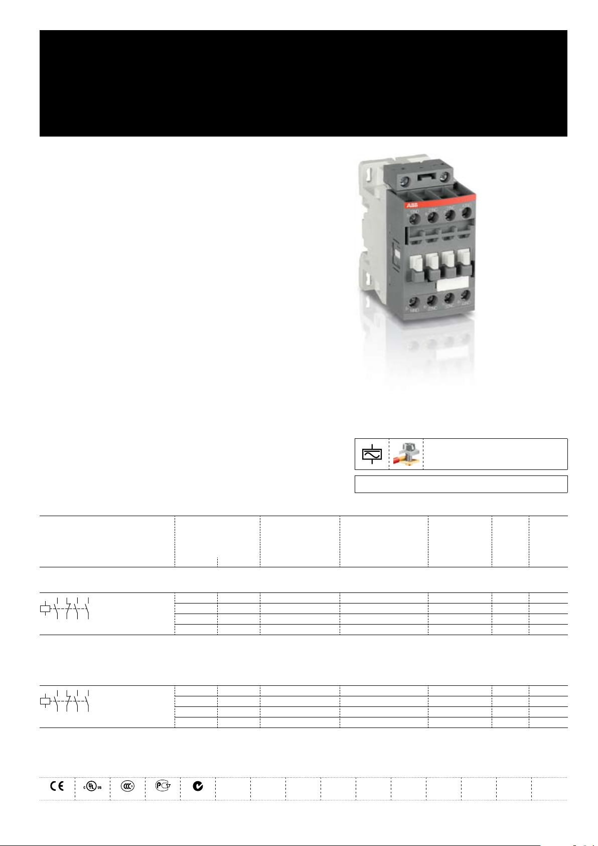
NF31E-.. / NFZ31E-.. Contactor Relays
AC / DC Operated - with Screw Terminals
NF(Z) contactor relays are used for switching auxiliary
and control circuits.
NF(Z) contactor relays include an electronic coil interface providing –
reduced pull-in and holding consumption, particularly for AC control
circuits
Only four coils are needed to cover control voltages between 24...500 V –
50/60 Hz or 20...500 V DC
NF(Z) offer extended operating limits and are suitable worldwide for
different control voltages. e.g.: the coil 100...250 V 50/60 Hz - DC is
suitable for Europe (230 V 50 Hz) and for North America (120 V 60 Hz
and 208 V 60 Hz).
NF(Z) contactors can manage large control voltage variations.
NFZ contactor relays equipped with a 24...60 V 50/60 Hz - 20...60 V DC –
coil allow direct control by 24 V DC 500 mA PLC-output
NFZ contactor relays withstand short voltage dips and voltage sags –
(SEMI F47-0706 compliance)
NF(Z) contactor relays have built-in surge protection and do not require –
additional surge suppressors
The contactor relays have mechanically-linked auxiliary contacts –
compliant with Annex L of IEC 60947-5-1 and include the "Mechanically
Linked" symbol on their side.
3D CAD outline drawings available on «Control Product 3D» portal
Ordering Details
Number of contacts Control voltage Type Order code EAN Weight
1st stack Uc min. ... Uc max.
Pack
(ing)
1 piece
V 50/60 Hz V DC
kg
Contactor Relays
24...60 20...60
48...130 48...130
100...250 100...250
250...500 250...500
Note: NF31E-11 not suitable for a direct control by PLC-output. NF31E-11 available in some countries: please consult your ABB representative.
NF31E-11 1SBH 137 001 R1131
NF31E-12 1SBH 137 001 R1231
NF31E-13 1SBH 137 001 R1331
NF31E-14 1SBH 137 001 R1431
3471523100213 0.270
3471523100220 0.270
3471523100237 0.270
3471523100244 0.310
Contactor Relays - Low Consumption
- 12...20
24...60 20...60
48...130 48...130
100...250 100...250
Note: Only NFZ contactor relays with DC control voltage 12...20 V DC need to respect the connection polarities indicated close to the coil terminals: A1+ for the positive pole and A2- for the negative pole
NFZ31E-20 1SBH 136 001 R2031
NFZ31E-21 1SBH 136 001 R2131
NFZ31E-22 1SBH 136 001 R2231
NFZ31E-23 1SBH 136 001 R2331
3471523101807 0.310
3471523101814 0.310
3471523101821 0.310
3471523101838 0.310
Certifications and Approvals
ABB | Technical Datasheet 1SBC101428D0201 1
2 Technical Datasheet 1SBC101428D0201 | ABB
Contact Utilization Characteristics according to IEC
Standards IEC 60947-1 / 60947-5-1 and EN 60947-1 / 60947-5-1
Rated operational voltage Ue max. 690 V
Conventional free-air thermal current Ith θ ≤ 40 °C 16 A
Rated frequency limits 25 ... 400 Hz
Rated operational current Ie / AC-15
acc. to IEC 60947-5-1
Making capacity AC-15 10 x Ie AC-15 acc. to IEC 60947-5-1
Breaking capacity AC-15 10 x Ie AC-15 acc. to IEC 60947-5-1
Rated operational current Ie / DC-13
acc. to IEC 60947-5-1
Short-circuit protection gG type fuse 10 A
Rated short-time withstand current I
cw
Minimum switching capacity 12 V / 3 mA
with failure rate acc. to IEC 60947-5-4
Non-overlapping time between N.O. and N.C. contacts ≥ 2 ms
Heat dissipation per pole at 6 A 0.1 W
Max. electrical switching frequency
24-127 V 50/60 Hz
220-240 V 50/60 Hz
400-440 V 50/60 Hz
500 V 50/60 Hz
690 V 50/60 Hz
24 V DC
48 V DC
72 V DC
110 V DC
125 V DC
220 V DC
250 V DC
400 V DC
500 V DC
600 V DC
for 1.0 s
for 0.1 s
AC-15
DC-13
6 A
4 A
3 A
2 A
2 A
6 A / 144 W
2.8 A / 134 W
1 A / 72 W
0.55 A / 60 W
0.55 A / 69 W
0.27 A / 60 W
0.27 A / 68 W
0.15 A / 60 W
0.13 A / 65 W
0.1 A / 60 W
100 A
140 A
-7
10
1200 cycles/h
900 cycles/h
Main Pole - Utilization Characteristics according to UL / CSA
Standards UL 508, CSA C22.2 N°14
Rated insulation voltage U
i
Max. rated voltage 600 V AC, 600 V DC
Pilot duty A600, Q600
AC thermal rated current 10 A
AC maximum volt-ampere making 7200 VA
AC maximum volt-ampere breaking 720 VA
DC thermal rated current 2.5 A
DC maximum volt-ampere making-breaking 69 VA
600 V
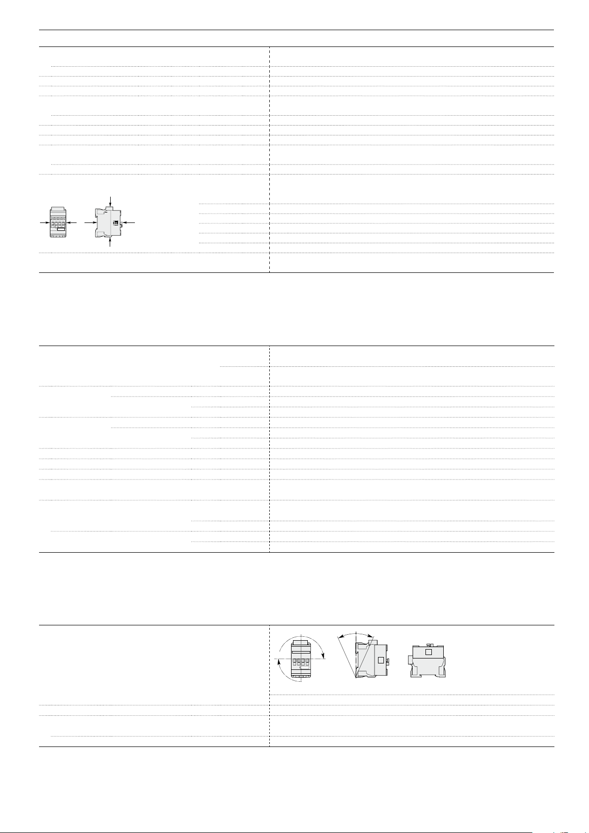
ABB | Technical Datasheet 1SBC101428D0201 3
General Technical Data
B2
A
A
B1
C2
C1
Pos. 5
Pos. 3
Pos
. 2
Pos. 1 Pos. 1 ± 30°
+30° -30°
Pos. 4
Rated insulation voltage Ui
acc. to IEC 60947-5-1
acc. to UL / CSA
Rated impulse withstand voltage Uimp 6 kV
Electromagnetic compatibility Devices complying with IEC 60947-1 / EN 60947-1 - Environment A
Ambient air temperature close to contactor
Operation in free air -40 ... +70 °C
Storage -60 ... +80 °C
Climatic withstand Category B according to IEC 60947-1 Annex Q
Operating altitude ≤ 3000 m
Mechanical durability
Number of operating cycles 20 millions operating cycles
Max. switching frequency 6000 cycles/h
Shock withstand
acc. IEC 60068-2-27 and EN 60068-2-27
Mounting position 1
Closed or open
Shock direction
position
Vibration withstand 5 ... 300 Hz
acc. to IEC 60068-2-6
690 V
600 V
1/2 sinusoidal shock for 11 ms: no change in contact position
A
30 g
B1
25 g Closed position / 5 g Open position
B2
15 g
C1
25 g
C2
25 g
4 g Closed position / 2 g Open position
Magnet System Characteristics
Coil operating limits
acc. to IEC 60947-5-1
AC control voltage Rated control circuit voltage Uc 24 ... 500 V AC
50/60 Hz Coil consumption
Average pull-in value
Average holding value
DC control voltage Rated control circuit voltage Uc 12 ... 500 V DC
Coil consumption
Average pull-in value
Average holding value
PLC-Output control (NFZ) ≥ 500 mA 24 V DC
Drop-out voltage in % of Uc min. ≤ 60 % Uc min
Voltage sag immunity according to SEMI F47-0706 (NFZ) conditions of use on request
Dips withstand (level 0% according to IEC 61000-4-11) (NFZ) 22 ms average for Uc = 24 ... 250 V 50/60Hz
-20 °C ≤ θ ≤ +60 °C
Operating time
between coil energization and:
between coil de-energization and:
N.O. contact closing
N.C. contact opening
N.O. contact opening
N.C. contact closing
AC supply
DC supply
at θ ≤ 60°C 0.85 x Uc min ... 1.1 x Uc max
at θ ≤ 70°C 0.85 x Uc min ... Uc max
at θ ≤ 60°C 0.85 x Uc min ... 1.1 x Uc max
at θ ≤ 70°C (NF) 0.85 x Uc min ... Uc max - (NFZ) 0.85 x Uc min ... 1.1 x Uc max
(NF) 50 VA - (NFZ) 16 VA
(NF) 2.2 VA / 2 W - (NFZ) 1.7 VA / 1.5 W
(NF) 50 W - (NFZ) 12 ... 16 W
(NF) 2 W - (NFZ) 1.7 W
40 ... 95 ms
38 ... 90 ms
11 ... 95 ms
13 ... 98 ms
Mounting Characteristics
Mounting positions
Max. add-on N.C. auxiliary contacts: see accessory fitting details for a NF contactor relay
Mounting distances The contactor relays can be assembled side by side.
Fixing
on rail according to IEC 60715, EN 60715 35 x 7.5 mm or 35 x 15 mm
by screws (not supplied) 2 x M4 screws placed diagonally
 Loading...