

Page 1
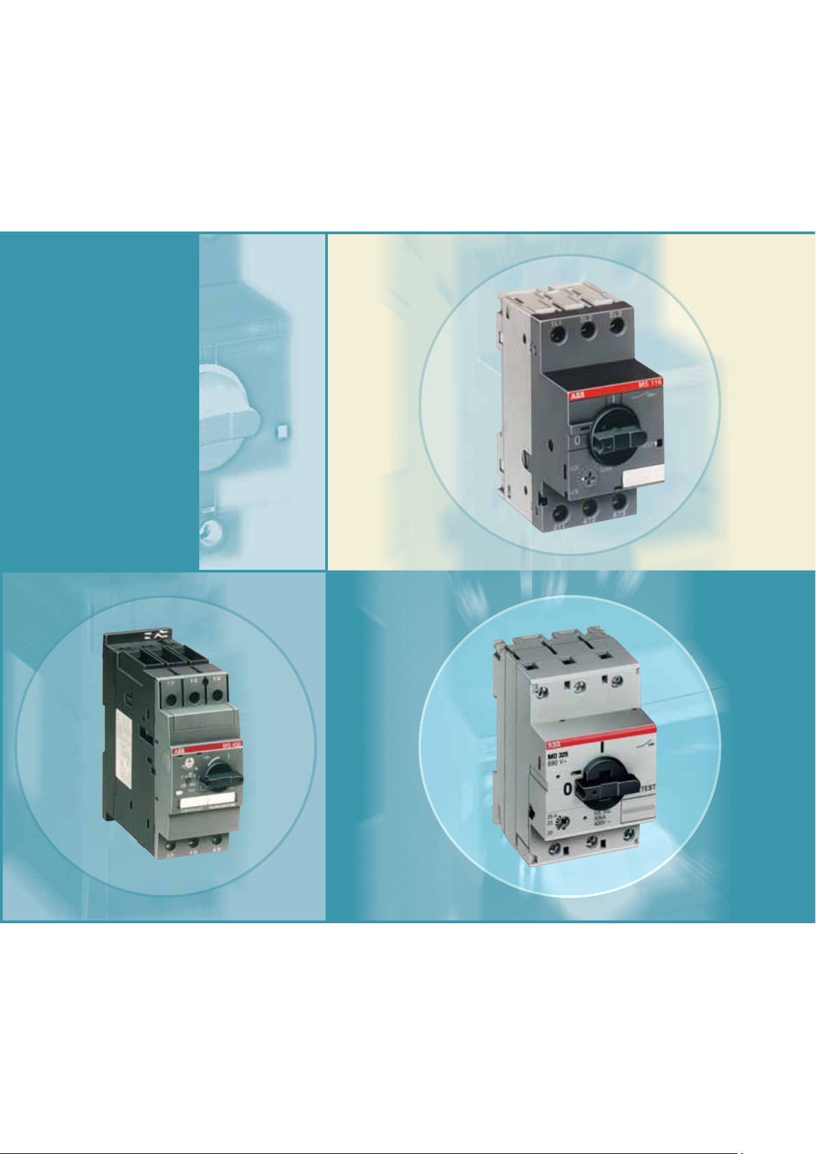
Technical Catalogue
Manual Motor Starters
MS116, MS325, MS4xx
ABB
1
Page 2

Manual Motor Starters
ABB
Type Series M up to 45 kW (400 V AC)
Contents
Manual Motor Starter MS116
0-16 A, 16/50 kA ................................................................................................................. 6
Manual Motor Starter MS325
0-25 A, 100 kA .................................................................................................................... 8
Manual Motor Starters MS45x
11-50 A, 25/50 kA ................................................................................................................. 12
Manual Motor Starters MS49x
11-50 A, 25/50/100 kA .......................................................................................................... 12
Manual Motor Starters MOxxx
up to 100 A, 25/50 kA ........................................................................................................... 14
Starter Combinations with Manual Motor Starters ......................................................... 16
Busbar System smissline-S
up to 200 A, 50 kA ................................................................................................................. 18
Technical data, Short circuit switching tables ...................................................................... 20
Dimension diagrams ............................................................................................................. 28
Examples, applications ........................................................................................................ 33
3
Page 3
Manual Motor Starters and Motor Starter Combinations
Manual motor starters from ABB properly switch motors ON
and OFF and protect them in case of overload and short
circuit.
Thus, ABB‘s manual motor starter know-how increases the
reliability and availability of applications thanks to the extremely quick short circuit cut-off in cases that could cause
motor damage.
ABB motor starter combinations constitute a reliable, costeffi cient solution for all your motor protection needs, for
examples in:
• General engineering and plants
• Industries
• Conveyor systems
• Chemical industries including process engineering
• Pharmaceutical industries
• Automation of buildings, e. g. in air-conditionings
• Environmental plants
• Power stations
• Fresh water and sewage plants
• Machine tools
Manual motor starters provide protection against:
• Overload
• Short circuit
• Phase failure
• Undervoltage
Fuseless protection saves costs and space and provides
for quick reaction under short circuit condition, switching
the motor off within 3 ms. It is therefore an easy to handle,
cost effective protection solution.
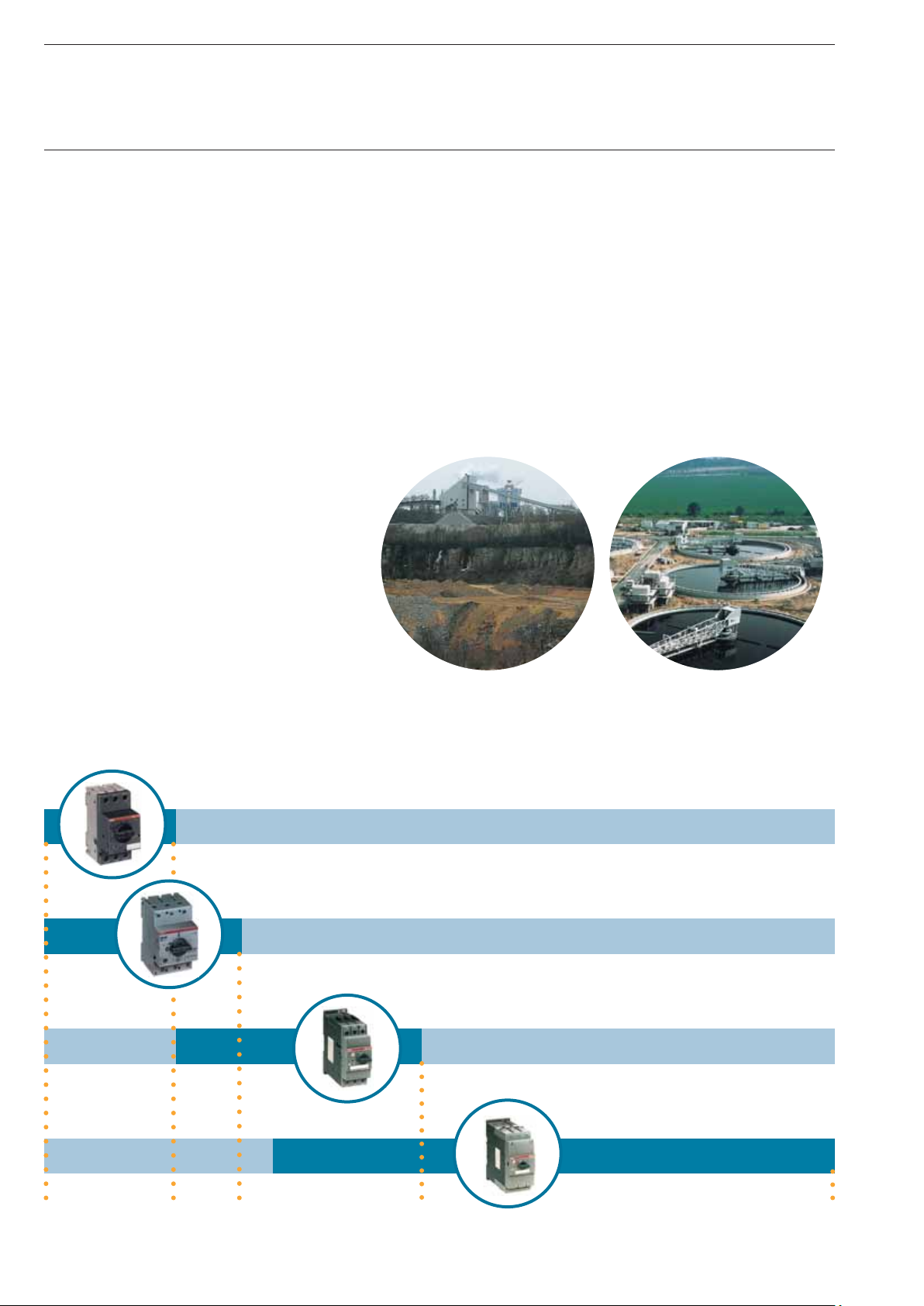
Switching capabilities of ABB‘s manual motor starters
Up to 16 A, 16/50 kA
Up to 25 A, 100 kA
Up to 50 A, 50 kA
Up to 100A, 50 kA
Type MS116
Type MS325
Type MS45x
Type MS49x
0.16 A
4
25 A 50 A 100 A16 A
Page 4
Manual Motor Starters from ABB
ABB offers a wide range of a manual motor starters providing highly effi cient motor protection up to 100 A.
The arc breaking capacity of the devices can reach
up to 100 kA depending of the motor starter type used,
without the necessity for any special upstream protection.
The device-types MS116/325 can be easily coordinated
with the ABB MCB-system, which is used in installations for
touch-proved enclosures and panels.
MS450 to MS497 are your best choice for high power applications. These models are used to power up large motors
up to 45 kW.
Thanks to its design MS116/325 are suitable for industrial
applicatons as well as for domestic installations.
Technical Data, Overview
Motorstarter type MS116 MS325 MS45x MS49x
/A 16 25 50 100
I
e
/kA 16/30/50 50/100 25/50 25/50/100
I
CS
Tripping class 10 10 10,20 10,20
Magnetic type only
Disconnect Capability, ● ● ● ●
ref. IEC 60947-1
UL 508 type E
● ● ●
● ● ●
The types MS325 have the lowest “energy let through”values on the market in case of short circuits.
This way cables and the wiring are also protected optimally, providing for even higher safety.
MO-types
No thermal
release
Tripping time
msec
Magnetic release
approx. 12 * I
e
Factor x I
e
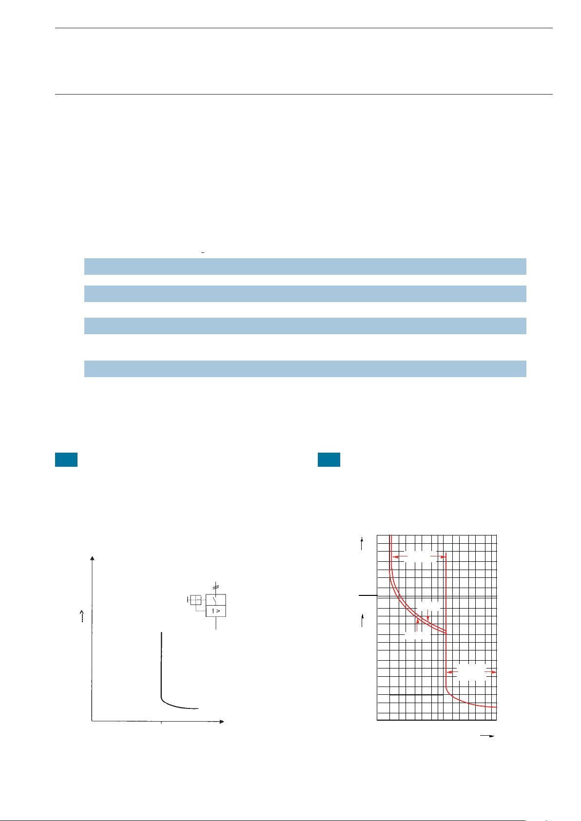
Manual motor starters must be set to the rated motor demand. Higher current is needed at motor start-up. During
the start-up period the manual motor starter will
let the current go through and will not trip, following the
pertaining international standards and curves for motor
start and hold operation.
MSx Tripping curves
100
0.05
0.02
0.01
0.005
0.002
0.001
50
20
10
5
2
50
20
10
5
2
1
0.5
0.2
0.1
Thermal
tripping
Three-pole
Two-pole
Electro-
magnetic
tripping
1 1.5 2 3 4 6 810 15 20 3040 6080
Multiple of the rated current
5
Page 5

MS116
HKF1-11
Manual Motor Starter MS116
Accessories
Ordering details
Type Setting range Order code Weight/ Packing
piece Unit
A...A kg piece
MS116 with thermal and electromagnetic trips, short-circuit-proof up to 50 kA
MS116 - 0.16 0.10 ... 0.16 1SAM 250 000 R1001 0.268 1
MS116 - 0.25 0.16 ... 0.25 1SAM 250 000 R1002 0.268 1
MS116 - 0.4 0.25 ... 0.40 1SAM 250 000 R1003 0.268 1
MS116 - 0.63 0.40 ... 0.63 1SAM 250 000 R1004 0.268 1
MS116 - 1.0 0.63 ... 1.00 1SAM 250 000 R1005 0.268 1
SST11601STO23014
MS116 - 1.6 1.00 ... 1.60 1SAM 250 000 R1006 0.268 1
MS116 - 2.5 1.60 ... 2.50 1SAM 250 000 R1007 0.268 1
MS116 - 4 2.50 ... 4.00 1SAM 250 000 R1008 0.268 1
MS116 - 6.3 4.00 ... 6.30 1SAM 250 000 R1009 0.268 1
MS116 - 10.0 6.30 ... 10.00 1SAM 250 000 R1010 0.268 1
MS116 - 12.0 8.00 ... 12.00 1SAM 250 000 R1012 0.268 1
MS116 - 16.0 10.00 ... 16.00 1SAM 250 000 R1011 0.268 1
Accessories
Type Order code Packing
Unit
piece
HK1
UA1
ST20-02
ST19-02
SK1
Auxillary switches, for front mounting
HKF1-11 1 NO + 1 NC 1SAM 201 901 R1001 10
Auxillary switches with lead contacts, also to use with undervoltage release
HK1-20L 2 NO lead contacts 1SAM 201 902 R1004 2
Auxiliary switches, lateral attechment at right
HK1-11 1 NO + 1 NC 1SAM 201 902 R1001 2
HK1-20 2 NO 1SAM 201 902 R1002 2
ST21-02
HK1-02 2 NC 1SAM 201 902 R1003 2
Shunt release, lateral mounting at the left side
AA1-24 24 V, 50/60 Hz 1SAM 201 910 R1001 1
AA1-110 110 V, 50/60 Hz 1SAM 201 910 R1002 1
AA1-230 200-240 V, 50/60 Hz 1SAM 201 910 R1003 1
AA1-400 350-415 V, 50/60 Hz 1SAM 201 910 R1004 1
Signal switch for general “tripped” signal, lateral attachment at right
SK1-11 1 NO + 1 NC 1SAM 201 903 R1001 2
SK1-20 2 NO 1SAM 201 903 R1002 2
SK1-02 2 NC 1SAM 201 903 R1003 2
Undervoltage release, lateral attachment at left
UA1-24 24 V, 50 Hz 1SAM 201 904 R1001 1
UA1-48 48 V, 50 Hz 1SAM 201 904 R1002 1
UA1-60 60 V, 50 Hz 1SAM 201 904 R1003 1
UA1-120 110 V 50 Hz/120 V 60 Hz 1SAM 201 904 R1004 1
UA1-208 208 V, 60 Hz 1SAM 201 404 R1008 1
UA1-230 230 V 50 Hz/240 V 60 Hz 1SAM 201 904 R1005 1
UA1-400 400 V, 50 Hz 1SAM 201 904 R1006 1
UA1-415 415 V 50 Hz/480 V 60 Hz 1SAM 201 904 R1007 1
Padlock + 2 keys + lock adapter
Direct adapter
6
S0109B91 + SK0150B91
STO18014
Locking device (see also MS325, Page 9)
SA1 lock adapter
GJF1 101 903 R0001 1
SA2 padlock + 2 keys GJF1 101 903 R0002 1
SA3 lock adapter + GJF1 101 903 R0003 1
padlock + 2 keys
FC116 fi xing clip for 1SAM 201 909 R1001
screw mounting
Direct adapter, for wiring to contactors
BEA7/116
mini contactors B6/B7 1SBN 080 906 R1000 1
BEA16/116 contactors A9/A12/A16 1SBN 081 406 R1000 1
BEA26/116 contactors A26 1SBN 082 406 R1000 1
Not suitable for panel mounting
Page 6
Phase buses PS1-2-1
Phase buses PS1-4-1
Manual Motor Starter MS116
Accessories
Ordering details
Accessories
Type Order cod Packing Price
Unit/piece
STO21014STO22014
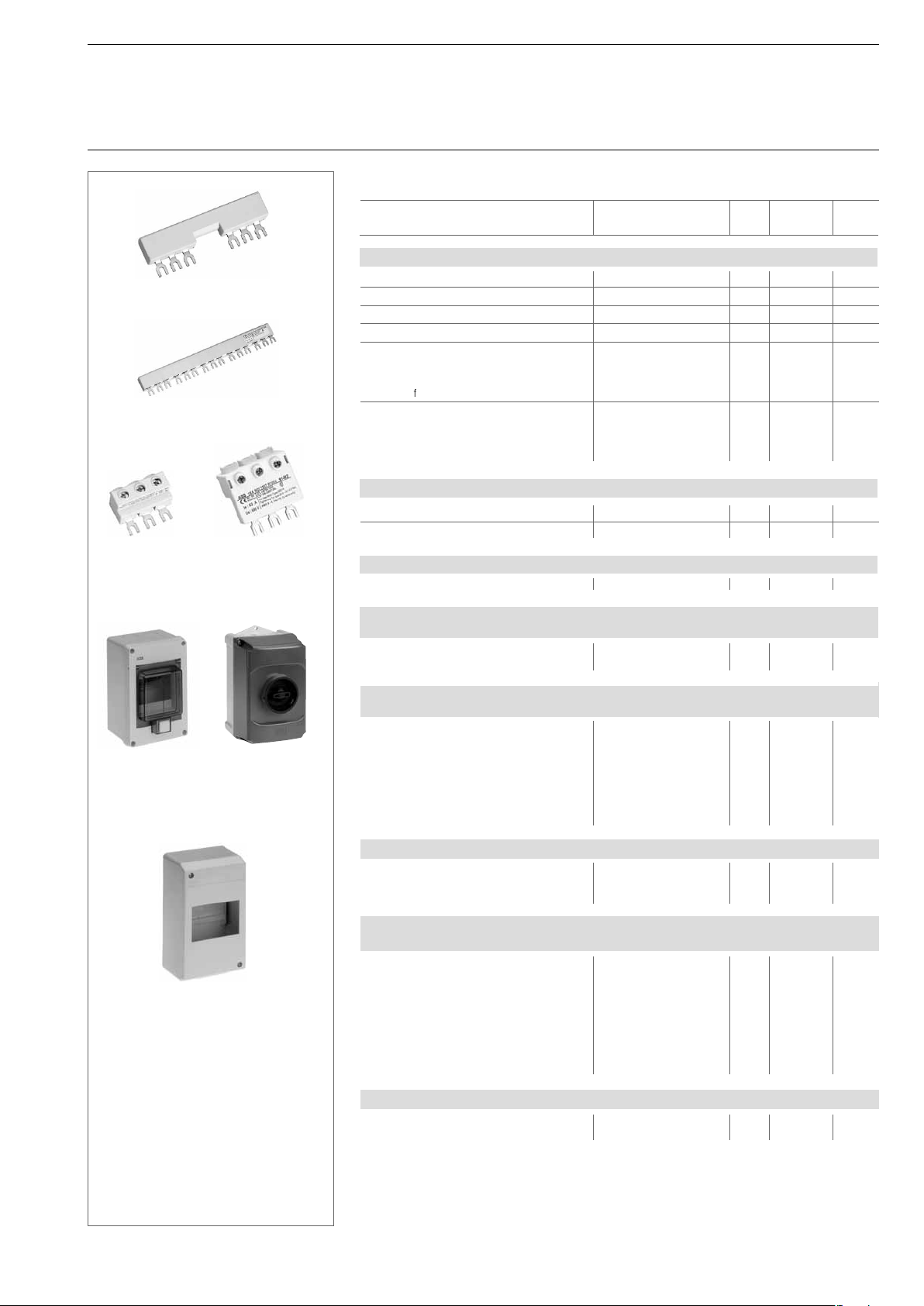
Phase buses for cross wiring MS116, 63 A, 690 V
PS1-2-0,
PS1-3-0,
PS1-4-0,
PS1-5-0,
PS1-2-1,
PS1-3-1,
PS1-4-1,
PS1-5-1,
PS1-2-2,
PS1-3-2,
PS1-4-2,
PS1-5-2,
for 2 devices without auxiliary switches 1SAM 201 906 R1002 10
for 3 devices without auxiliary switches 1SAM 201 906 R1003 10
for 4 devices without auxiliary switches 1SAM 201 906 R1004 10
for 5 devices without auxiliary switches 1SAM 201 906 R1005 10
for 2 devices with 1 auxiliary switch 1SAM 201 906 R1012 10
for 3 devices with 1 auxiliary switch 1SAM 201 906 R1013 10
for 4 devices with 1 auxiliary switch 1SAM 201 906 R1014 10
for 5 devices with 1 auxiliary switch 1SAM 201 906 R1015 10
for 2 devices with 2 auxiliary switches 1SAM 201 906 R1022 10
for 3 devices with 2 auxiliary switches 1SAM 201 906 R1023 10
for 4 devices with 2 auxiliary switches 1SAM 201 906 R1024 10
for 5 devices with 2 auxiliary switches 1SAM 201 906 R1025 10
STO19014
Power infeed
block S1-M1
STO28014
Insulating enclosure IP55
Plastic enclosure IP40
Power infeed
block S1-M2
Insulating
enclosure IP65
STO27014
STO20014
GEH_uses
Power infeed blocks, 63 A, 690 V, stranded 25 mm
2
, fl exible 16 mm
2
S1-M1, fl at 1SAM 201 907 R1001 10
S1-M2, high 1SAM 201 907 R1002 10
Cover for phase busses
BS1-3 1SAM 201 908 R1001 50
Insulating enclosure IP65, with rotary handle, triple lockable in Off position,
with N- und PE-terminal, for Manual Motor Starter
IB116-G, Twist knob black 1SAM 201 911 R1000 1
IB116-Y, Twist knob red/yellow 1SAM 201 911 R1001 1
Insulating enclosure, light grey IP55 with cover, including DIN rail
for manual motor starter or line protection devices
QES4/3N, for 4 modules, 72 mm GHL 111 2304 R0013
QES6/3N, for 6 modules, 108 mm GHL 111 2306 R0013
QES10/3N, for 10 modules, 180 mm GHL 111 2310 R0013
Set of neutral and earth terminals
SMO4, for QES 4/3 N GHL 430 1910 R0004
SMO6, for QES 6/3 N GHL 430 1910 R0006
SMO10, for QES 10/3 N GHL 430 1910 R0010
Plastic enclosure, light grey, IP40 in panel design, including DIN rail
PCD4N, for 4 modules, 72 mm GHS 270 1921 R0004
PCD6N, for 6 modules, 108 mm GHS 270 1921 R0006
PCD8N, for 8 modules, 144 mm GHS 270 1921 R0008
Switch cubicle mounting kit IP65, with axial extension
triple lockable in Off position, locked in On position
OHB2AJM, Twist knob black 1SCA 022 384 R6940 1
OHY2AJM, Twist knob red/yellow 1SCA 022 384 R7080 1
OXS5X85, axis 85 mm 1SCA 022 347 R3570 1
OXS5X105, axis 105 mm 1SCA 022 347 R3650 1
OXS5X130, axis 130 mm 1SCA 022 353 R4540 1
OXS5X180, axis 180 mm 1SCA 022 353 R4620 1
MSMN, driver 1SAM 101 923 R0001 1
MSOX, driver spindle 32 mm 1SAM 101 924 R0001 1
Door mounting kit IP65, Lockable in Off-position
DMS116-G, Twist knob black 1SAM 201 912 R1000 1
DMS116-Y, Twist knob red/yellow
For accommodating spindle and attachment to manual motor starter
Is srewed directly onto the manual motor starter
1SAM 201 912 R1001 1
7
Page 7
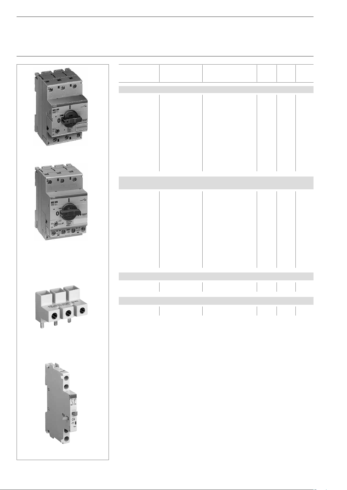
MS325
MS325 with
auxiliary contacts HKF-11
front mounting
Manual Motor Starter MS325
Ordering details
Type Setting range Order code Weight/ Packing Price
piece Unit
A...A kg piece
MS325 with thermal and electromagnetic trips, short-circuit-proof up to 100 kA
MS325 – 0.16 0.10 ... 0.16 1SAM 150 000 R1001 0.347 1
MS325 – 0.25 0.16 ... 0.25 1SAM 150 000 R1002 0.347 1
MS325 – 0.4 0.25 ... 0.40 1SAM 150 000 R1003 0.347 1
MS325 – 0.63 0.40 ... 0.63 1SAM 150 000 R1004 0.347 1
MS325 – 1 0.63 ... 1.00 1SAM 150 000 R1005 0.347 1
SST01497
SST 02899
MS325 – 1.6 1.00 ... 1.60 1SAM 150 000 R1006 0.347 1
MS325 – 2.5 1.60 ... 2.50 1SAM 150 000 R1007 0.347 1
MS325 – 4 2.50 ... 4.00 1SAM 150 000 R1008 0.347 1
MS325 – 6.3 4.00 ... 6.30 1SAM 150 000 R1009 0.347 1
MS325 – 9 6.30 ... 9.00 1SAM 150 000 R1010 0.347 1
MS325 – 12.5 9.00 ... 12.50 1SAM 150 000 R1011 0.347 1
MS325 – 16 12.50 ... 16.00 1SAM 150 000 R1012 0.347 1
MS325 – 20 16.00 ... 20.00 1SAM 150 000 R1013 0.347 1
MS325 – 25 20.00 ... 25.00 1SAM 150 000 R1014 0.347 1
MS325 with thermal and electromagnetic trips, short-circuit-proof up to 100 kA,
with auxiliary switch 1 NO + 1 NC front mounted
MS325 – 0.16 0.10 ... 0.16 1SAM 150 005 R0001 0.359 1
MS325 – 0.25 0.16 ... 0.25 1SAM 150 005 R0002 0.359 1
MS325 – 0.4 0.25 ... 0.40 1SAM 150 005 R0003 0.359 1
MS325 – 0.63 0.40 ... 0.63 1SAM 150 005 R0004 0.359 1
MS325 – 1 0.63 ... 1.00 1SAM 150 005 R0005 0.359 1
MS325 – 1.6 1.00 ... 1.60 1SAM 150 005 R0006 0.359 1
MS325 – 2.5 1.60 ... 2.50 1SAM 150 005 R0007 0.359 1
MS325 – 4 2.50 ... 4.00
MS325 – 6.3 4.00 ... 6.30 1SAM 150 005 R0009 0.359 1
MS325 – 9 6.30 ... 9.00 1SAM 150 005 R0010 0.359 1
MS325 – 12.5 9.00 ... 12.50 1SAM 150 005 R0011 0.359 1
MS325 – 16 12.50 ... 16.00 1SAM 150 005 R0012 0.359 1
MS325 – 20 16.00 ... 20.00 1SAM 150 005 R0013 0.359 1
MS325 – 25 20.00 ... 25.00 1SAM 150 005 R0014 0.359 1
1SAM 150 005 R0008 0.359 1
S3-M3
CK-11
UL 508 Type E Accessories
S3-M3 High insulation 1SAM 101 938 R0004 0.030 1
infeed block
Signal switch for short circuit tripping, lateral attachment at right
CK-11 1 NO + 1 NC 1SAM 101 943 R0001 0.030 2
2CDC 241 008 F0042CDC 241 004 F004
8
Page 8
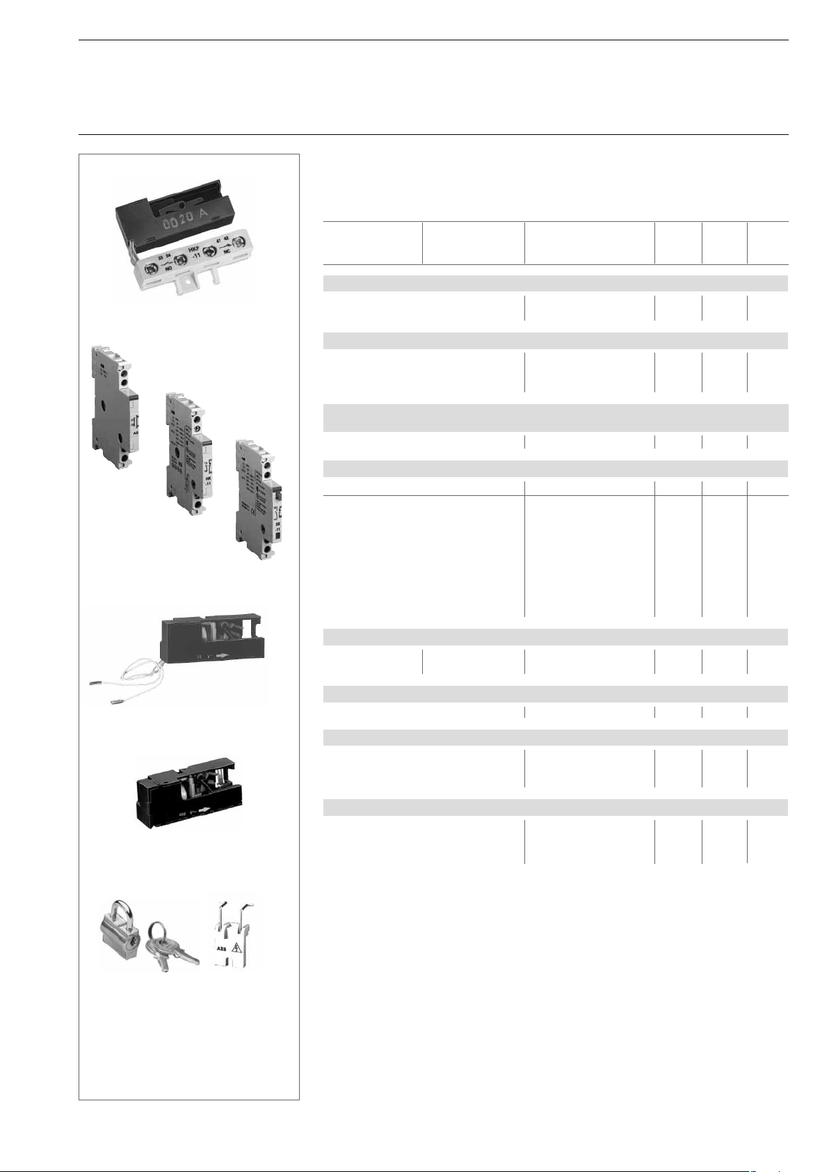
AS
HKF
2CDC 241 006 F004
HK
Manual Motor Starters MS325
Accessories
Ordering details
Retrofi ttable accessories
These parts can be procured in addition to the MS325; they must be installed by the user.
Type Setting range Order code Weight/ Packing Price
63-00
2CDC 241 011 F004
SK
piece Unit
kg piece
Auxiliary switches, for front mounting
HKF-11 1 NO + 1 NC 1SAM 101 928 R0001 0.020 10
HKF-20 2 NO 1SAM 101 928 R0002 0.020 10
Auxiliary switches, lateral attachment at left, max. 2 pieces attachable
HK-11 1 NO + 1 NC 1SAM 101 901 R0001 0.031 2
HK-20 2 NO 1SAM 101 901 R0002 0.031 2
HK-02 2 NC 1SAM 101 901R0003 0.031 2
Signal contact for general “tripped” signal, lateral attachment at the left
max. 1 piece attachable
SK-11 1 NO + 1 NC 1SAM 101 904 R0003 0.031 2
Undervoltage release, slide-in
UA, power infeed at bottom, U
400 V~ 1SAM 101 902 R0400 0.02 10
c
UAF, power infeed at top,
resp. connection UC 24 V~ 1SAM 101 903 R0024 0.02 10
of external voltage 48 V~ 1SAM 101 903 R0048 0.02 10
60 V~ 1SAM 101 903 R0060 0.02 10
2CDC 241 005 F004
110 V~ 1SAM 101 903 R0110 0.02 10
230 V~ 1SAM 101 903 R0230 0.02 10
400 V~ 1SAM 101 903 R0400 0.02 10
415 V~ 1SAM 101 903 R0415 0.02 10
500 V~ 1SAM 101 903 R0500 0.02 10
SST 309 92 R
SST30992R
UA for power in feed at top, AA
SST 032 95 R
UA for power in feed at bottom
Padlock + 2 keys + lock adapter
Open circuit shunt release, slide-in
AA 24 ... 60 V AC/DC 1SAM 101 909 R0001 0.02 10
AA 110... 240 V AC/DC 1SAM 101 909 R0002 0.02 10
Terminal support, lateral attachment at left to MS325, HK and SK
AS, for UA, AA or as N/LS terminal 1SAM 101 905 R0001 0.031 10
Locking device for MS325
SA1, lock adapter GJF1 101 903 R0001 0.004 10
SA2, padlock + 2 keys GJF1 101 903 R0002 0.004 10
SA3, lock adapter + padlock + 2 keys GJF1 101 903 R0003 0.050 1
Printadapter, for soldering on electronic plates
PA25, for MS325 and 1SAM 101 933 R0001 0.030 1 kit
2 aux. contacts
Not simultaneously with UA/UA and AA, not suitable for distributor installation
Max. 1 piece in conjunction with SK. SK must be mounted on fi rst position
Pre-mating normally open contacts
Can be used together with UAF (power infeed at top) for safety circuit with Emergency Stop button
(further information available on request)
Other voltages, in particular DC, on request
S0109B91 + SK0150B91
In particular if used with socke busbar system smissline-S (see Page 19)
Recommendation: Connection of external voltage via terminal support AS
9
Page 9
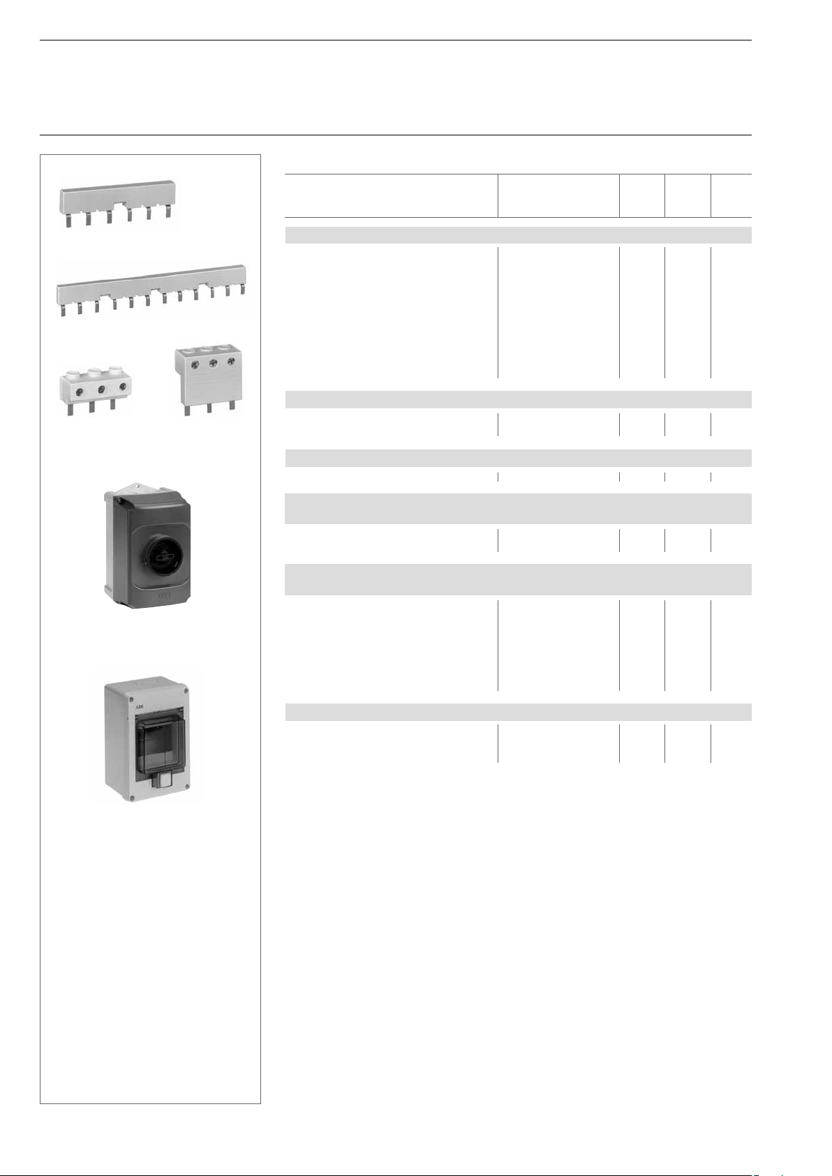
Phase buses PS3-2-1
Phase buses PS3-4-1
SST 022 93 R
Power infeed
block S3-M1
SST 023 93 R
Power infeed
block S3-M2
Manual Motor Starters MS325
Accessories
Ordering details
Accessories
Type Order code Weight/ Packing Price
piece unit
kg piece
Phase buses for cross wiring MS325, 63 A, 690 V
PS3-2-0, for 2 dev., without aux. switch 1SAM 101 937 R0012 10
PS3-3-0, for 3 dev., without aux. switch 1SAM 101 937 R0013 10
PS3-4-0, for 4 dev., without aux. switch 1SAM 101 937 R0014 10
PS3-5-0, for 5 dev., without aux. switch 1SAM 101 937 R0015 10
SST 024 93 R
PS3-2-1, for 2 dev., with 1 aux. switch 1SAM 101 937 R0022 10
PS3-3-1, for 3 dev., with 1 aux. switch 1SAM 101 937 R0023 10
PS3-4-1, for 4 dev., with 1 aux. switch 1SAM 101 937 R0024 10
PS3-5-1, for 5 dev., with 1 aux. switch 1SAM 101 937 R0025 10
PS3-2-2, for 2 dev., with 2 aux. switches 1SAM 101 937 R0032 10
PS3-4-2, for 4 devices, with 2 aux. swit. 1SAM 101 937 R0034 10
SST 021 93 R
Power infeed blocks, 63 A, 690 V, stranded 25 mm
S3– M1, fl at 1SAM 101 938 R0001 10
S3– M2, high 1SAM 101 938 R0002 10
Cover for busbars (for not used poles)
BS3-3 1SAM 101 938 R0003 50
2
, fl exible 16 mm
2
Insulating
enclosure IP65
Insulating en-
closure IP55
STO28014
Insulating enclosure IP65 with rotary handle, triple lockable in Off position,
with N- und PE-terminal, for Manual Motor Starter
IB325-G, Twist knob black 1SAM 101 940 R1000 1
IB325 Y, Twist knob red/yellow 1SAM 101 940 R1001 1
Insulating enclosure, light grey IP55 with cover, including DIN rail
for manual motor starter or line protection devices
QES4/3N, for 4 modules, 72 mm GHL 111 2304 R0013 1
QES6/3N, for 6 modules, 108 mm GHL 111 2306 R0013 1
QES10/3N, for 10 modules, 180 mm GHL 111 2310 R0013 1
Set of neutral and earth terminals
SMO4, for QES 4/3 N GHL 430 1910 R0004 1
SMO6, for QES 6/3 N GHL 430 1910 R0006 1
SMO10, for QES 10/3 N GHL 430 1910 R0010 1
Plastic enclosure, light grey, IP40 in panel design, including DIN rail
PCD4N, for 4 modules, 72 mm GHS 270 1921 R0004 1
PCD6N, for 6 modules, 108 mm GHS 270 1921 R0006 1
PCD8N, for 8 modules, 144 mm GHS 270 1921 R0008 1
10
Page 10
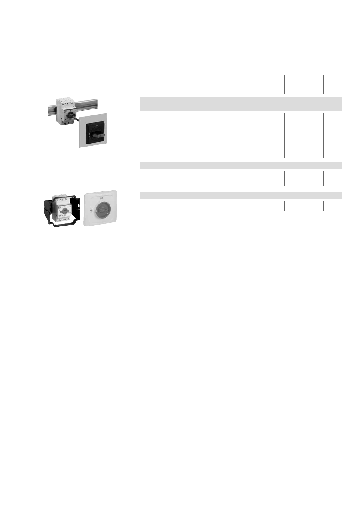
Switch cubicle
mounting kit
Door mounting kit
Manual Motor Starters MS325
Accessories
Ordering details
Accessories
Type Order code Weight/ Packing Price
piece unit
kg piece
Switch cubicle mounting kit IP65, with axial extension
triple lockable in Off position, locked in On position
OHB2AJM, Twist knob black 1SCA 022 384 R6940 1
OHY2AJM,Twist knob red/yellow 1SCA 022 384 R7080 1
OXS5X 85, axis 85 mm 1SCA 022 347 R3570 1
OXS5X105, axis 105 mm 1SCA 022 347 R3650 1
2CDC 243 008 F005
2CDC 241 001 F003
OXS5X130, axis 130 mm 1SCA 022 353 R4540 1
OXS5X180, axis 180 mm 1SCA 022 353 R4620 1
MSMN, driver 1SAM 101 923 R0001 1
MSOX, driver spindle 32 mm 1SAM 101 924 R0001 1
Direct adapter MS325
BEA7/325, direct adapter MS325 to B6/B7 1SBN 080 906 R1001 0.021 10
BEA16/325,
BEA26/325, direct adapter MS325 to A26 1SBN 082 406 R1001 0.031 10
Door mounting kit IP65, Lockable in Off-position
DMS325-G, grey handle 1SAM 101 941 R1000 1
DMS325-Y, red/yellow handle 1SAM 101 941 R1001 1
For accommodating spindle and attachment to manual motor starter
Is screwed directly onto the manual motor starter
Only suitable for MS325
See also page 34
direct adapter MS325 to A9/A12/A16
1SBN 081 406 R1001 0.031 10
11
Page 11
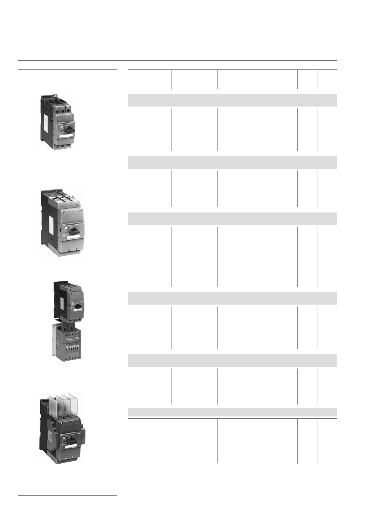
MS45x
Manual Motor Starters MS4xx
Ordering details
Type Setting range Order code Weight / Packing Price
piece unit
A . . . A kg piece
MS450 with thermal and electromagnetic trips, tripping class 10,
short-circuit-proof up to 50 kA
MS450 – 16 11 ... 16 1SAM 450 000 R1001 0.96 1
MS450 – 20 14 ... 20 1SAM 450 000 R1002 0.96 1
MS450 – 25 18 ... 25 1SAM 450 000 R1003 0.96 1
MS450 – 32 22 ... 32 1SAM 450 000 R1004 0.96 1
MS450 – 40 28 ... 40 1SAM 450 000 R1005 0.96 1
MS450 – 45 36 ... 45 1SAM 450 000 R1006 0.96 1
SST02198
MS450 – 50 40 ... 50 1SAM 450 000 R1007 0.96 1
MS495 with thermal and electromagnetic trips, tripping class 10,
short-circuit-proof up to 50 kA
MS495 – 40 28 ... 40 1SAM 550 000 R1005 2.1 1
MS495 – 50 36 ... 50 1SAM 550 000 R1006 2.1 1
MS495 – 63 45 ... 63 1SAM 550 000 R1007 2.1 1
MS495 – 75 57 ... 75 1SAM 550 000 R1008 2.1 1
MS495 – 90 70 ... 90 1SAM 550 000 R1009 2.1 1
MS495 – 100 80 ... 100 1SAM 550 000 R1010 2.1 1
SST01898
MS49x
ST14-02
MS495 with A95
connected via BEA 110/495
MS497 with thermal and electromagnetic trips, tripping class 10,
short-circuit-proof up to 100 kA
MS497 – 16 11 ... 16 1SAM 580 000 R1001 2.1 1
MS497 – 20 14 ... 20 1SAM 580 000 R1002 2.1 1
MS497 – 25 18 ... 25 1SAM 580 000 R1003 2.1 1
MS497 – 32 22 ... 32 1SAM 580 000 R1004 2.1 1
MS497 – 40 28 ... 40 1SAM 580 000 R1005 2.1 1
MS497 – 50 36 ... 50 1SAM 580 000 R1006 2.1 1
MS497 – 63 45 ... 63 1SAM 580 000 R1007 2.1 1
MS497 – 75 57 ... 75 1SAM 580 000 R1008 2.1 1
MS497 – 90 70 ... 90 1SAM 580 000 R1009 2.1 1
MS497 – 100 80 ... 100 1SAM 580 000 R1010 2.1 1
MS451 with thermal and electromagnetic trips, tripping class 20,
for heavy start short-circuit-proof up to 50 kA
MS451 – 16 11 ... 16 1SAM 470 000 R1001 0.96 1
MS451 – 20 14 ... 20 1SAM 470 000 R1002 0.96 1
MS451 – 25 18 ... 25 1SAM 470 000 R1003 0.96 1
MS451 – 32 22 ... 32 1SAM 470 000 R1004 0.96 1
MS451 – 40 28 ... 40 1SAM 470 000 R1005 0.96 1
MS451 – 45 36 ... 45 1SAM 470 000 R1006 0.96 1
MS451 – 50 40 ... 50 1SAM 470 000 R1007 0.96 1
MS496 with thermal and electromagnetic trips, tripping class 20,
for heavy start short-circuit-proof up to 100 kA
MS496 – 40 28 ... 40 1SAM 570 000 R1005 2.1 1
MS496 – 50 36 ... 50 1SAM 570 000 R1006 2.1 1
MS496 – 63 45 ... 63 1SAM 570 000 R1007 2.1 1
MS496 – 75 57 ... 75 1SAM 570 000 R1008 2.1 1
MS496 – 90 70 ... 90 1SAM 570 000 R1009 2.1 1
MS496 – 100 80 ... 100 1SAM 570 000 R1010 2.1 1
MS495 with auxiliary switch
HKS4-02 and open-circuit shunt
release AA4 in addition to terminal shroud KA495C
12
SST 09498
Direct adapter for wiring MS450 - MS497 to contactors
Type Order code Weight / Packing Price
piece unit
kg piece
BEA40/450,
BEA50/450,
BEA75/495,
BEA110/495,
See table on Page 24, Max. motor current 95 A
direct adapter MS450 to A30/A40 1SBN 083 206 R1000 0.061 1
direct adapter MS450 to A50 plate 1SBN 083 506 R1000 0.062 1
direct adapter MS495-497to A50/63/75 1SBN 084 106 R1000 0.120 1
direct adapter MS495-497 to A95/A110 1SBN 084 506 R1000 0.124 1
Page 12
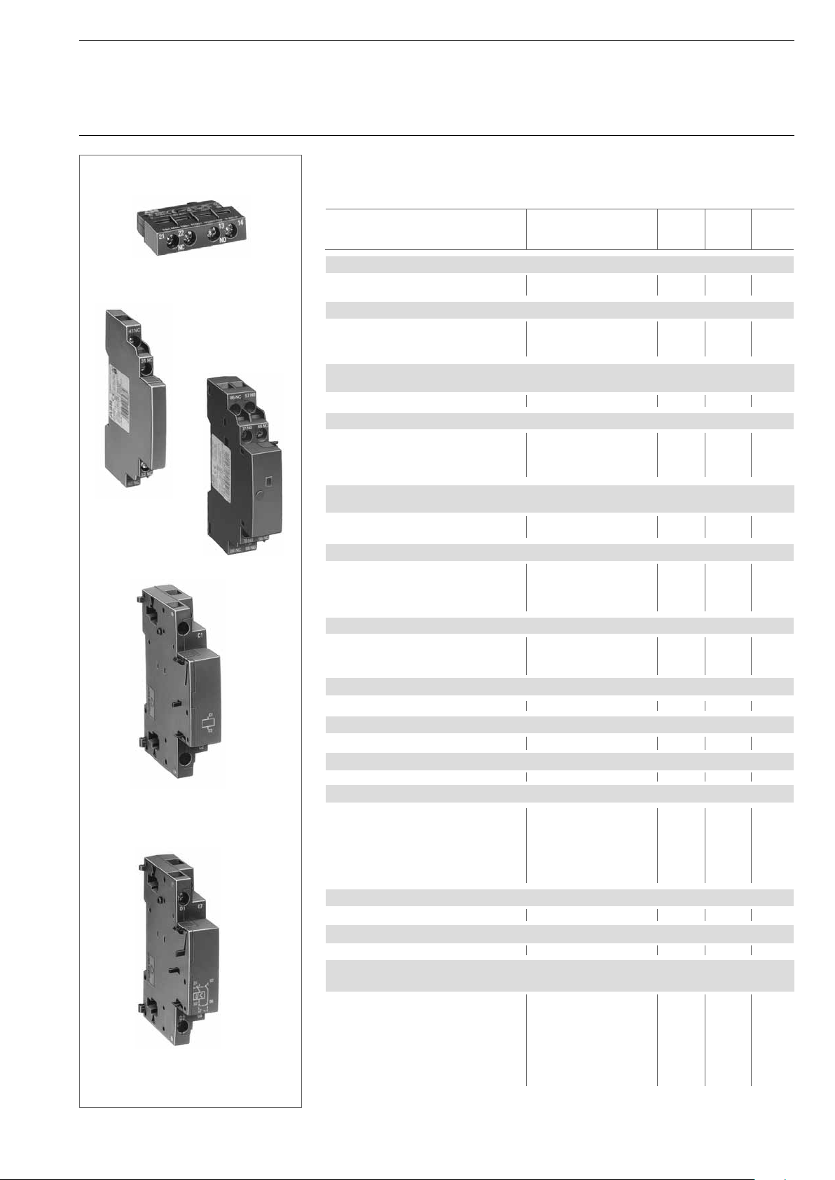
Auxiliary switch HK4-11
Auxiliary switch
HKS4-02
Open-circuit shunt
release AA4
Undervoltage release
UA4-HK
SST08598
Manual Motor Starters MS4xx
Accessories
Ordering details
SST09198
Pilot switch
SK4-11
SST07798
SST8698
Retrofi ttable accessories
These parts may be procured in addition to the MS4xx.
They must be mounted by the user.
Type Order code Weight/ Packing Price
piece unit
kg piece
Auxiliary switches, for front mounting
HK4-11, 1 NO + 1NC 1SAM 401 901 R1001 0.02 10
HK4-W, 1 Changeover 1SAM 401 901 R1002 0.02 10
Auxiliary switches, for lateral attachment at left, max. 1 mountable
HKS4-11, 1 NO + 1 NC 1SAM 401 902 R1001 0.03 2
HKS4-20, 2 NO 1SAM 401 902 R1002 0.03 2
HKS4-02, 2 NC 1SAM 401 902 R1003 0.03 2
Signal switch for separate signalling acc. UL508 type E, lateral attachment at left
1NO + 1NC for short circuit signalling, 1NO + 1NC for general tripping
SK4-11 2x: 1NO + 1NC 1SAM 401 904 R 1001 0.07 1
Undervoltage release, for lateral attachment at right
UA4, 24 V 50 Hz 1SAM 401 905 R1004 0.12 1
UA4, 110 V 50 Hz 1SAM 401 905 R1001 0.12 1
UA4, 230 V 50 Hz / 240 V 60 H 1SAM 401 905 R1002 0.12 1
UA4, 400 V 50 Hz 1SAM 401 905 R1003 0.12 1
Undervoltage release with pre-mating auxiliary switch 2 NO,
for lateral attachment at right
UA4-HK, U
SST 01599
UA4-HK, 400 V 50 Hz 1SAM 401 906 R1002 0.13 1
Shunt release, lateral mounting at the left side
AA4, 20-70 V, 50/60 Hz 1SAM 401 907 R1001 0.11 1
AA4, 70-190 V, 50/60 Hz 1SAM 401 907 R1002 0.11 1
AA4, 190-330 V, 50/60 Hz 1SAM 401 907 R1003 0.11 1
AA4, 330-500 V, 50/60 Hz 1SAM 401 907 R1004 0.11 1
Terminal shroud, for additional shock-hazard protection
KA450, for MS45x 1SAM 401 908 R1001 0.01 1
KA495, for MS49x
KA495C, for MS49x
Terminal insulation barrier,
DX495
Scale cover, lead-sealable
SA450, for MS45x 1SAM 401 909 R1001 0.007 1 set
Disconnector module, for producing a visible gap, lockable
TB450, for MS45x 1SAM 401 910 R1001 0.30 1
Phase busses MS45x, 108 A, 690 V
PS4-2 without HK, for 2 devices 1SAM 401 911 R1001
PS4-3 without HK, for 3 devices 1SAM 401 911 R1002
PS4-4 without HK, for 4 devices 1SAM 401 911 R1003
PS4-2 with HK, for 2 devices 1SAM 401 911 R1004
PS4-3 with HK, for 3 devices 1SAM 401 911 R1005
PS4-4 with HK, for 4 devices 1SAM 401 911 R1006
Infeed block, 108 A, 690 V, Stranded 50 mm
S4-M1, fl at 1SAM 401 911 R1007 10
Cover for phase bus poles
BS4-3 1SAM 401 911 R1008
Switch cubicle mounting kit IP65, with axial extension, lockable in Off position, locked
in On position
OHB2AJM, Twist knob black 1SCA 022 384 R6940
OHY2AJM, Twist knob red/yellow 1SCA 022 384 R7080
OXS5X 85, axis 85 mm 1SCA 022 347 R3570
OXS5X105, axis 105 mm 1SCA 022 347 R3650
OXS5X130, axis 130 mm 1SCA 022 353 R4540
OXS5X180, axis 180 mm 1SCA 022 353 R4620
MSMN, driver 1SAM 101 923 R0001
Is plugged onto the box terminals in each case
switch
Is plugged onto the housing after removing See also MS325 Page 10
the box terminals, if using cable lugs or buses Is screwed directly onto the manual motor starter
Supplied only as a set as 10 scale covers
230 V 50 Hz / 240 V 60 Hz 1SAM 401 906 R1001 0.13 1
c
1SAM 501 901 R1001 0.01 1
1SAM 501 902 R1001 0.03 1
necessary for UL 508E, MS49x-Starter 1SAM 401 912 R1001
2
, fi nely stranded 35 mm
Mounting sequence: Motor protection switch, pilot switch, auxiliary
Max. ON time: 5 seconds, see also Page 22
2
13
Page 13
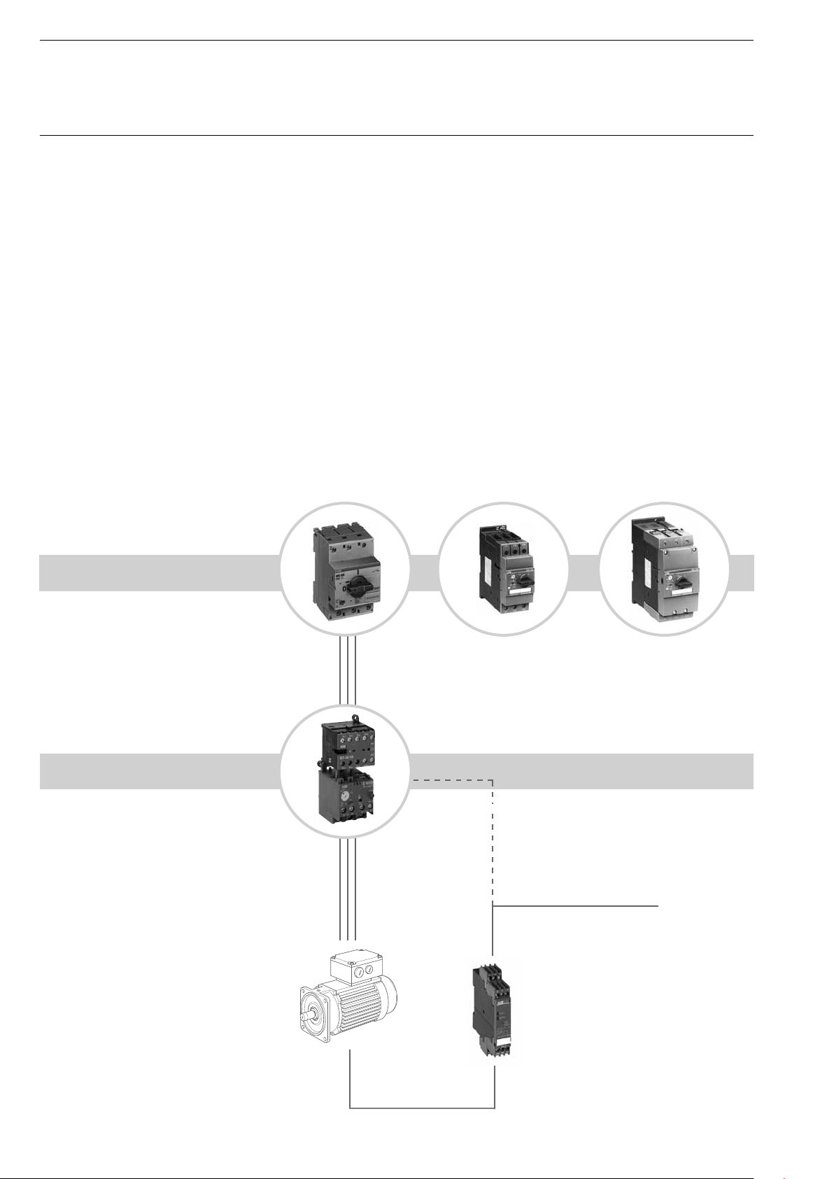
Strategies for motor protection with magnetic only types MO
For special applications ABB’s manual motor starter
of the MS series are also available as versions
MO325 / MO450 / MO495 with magnetic tripping only,
protecting exclusively against short circuits.
However, combined with intelligent ABB-components,
the starter series MO open up further interesting
alternatives for the use of motor starters, especially when
short circuit protection and thermal protection have to be
realized independent from one another.
Examples for motor protection
up to 25 A up to 50 A up to 100 A
Short circuit protection
with MO-circuit breakers
Therefore three different strategies of motor protection
with manual motor starters MO from ABB are feasible:
1. With thermal overload relays:
cost effi cient protection against overload and
phase failure
2. With electronic overload relays:
For high accuracy and effi cient stock planing,
less types for the complete range, high
fl exibility.
3. Thermistor motor protection:
High accuracy with temperature monitoring
directly in the coil, highly effi cient protection
with several electronic posibilities.
14
Thermal overlaod protection
including phase failure detection
Signal to PLC or contactors
Thermistor Motor protection
against overheating
Sensors for
temperature measurement
Page 14
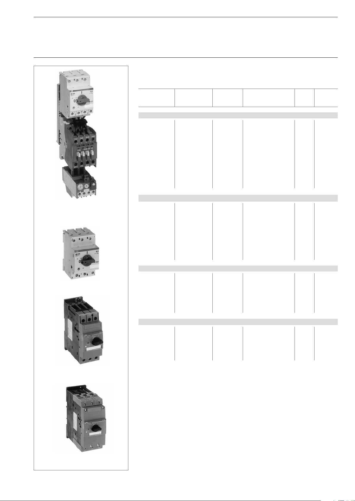
ST03101
MO325 + A26 + TA25DU
Magnetic only types
MOxxx
Ordering details, Technical data
Devices with only electromagnetic tripping for short circuit protection
The MO-types are used as MCB, mainly in combinations with other coordinated products
for branch protection.
Type rated current Short circuit Order code Weight / Packing
trip range piece unit
kg piece
MO325, short-circuit – capacity up to 100kA and 50 kA
MO325-0.4 0,4 3 - 4.8 1SAM 160 000 R1003 0.347 1
MO325-0.63 0,63 4.8 - 7.6 1SAM 160 000 R1004 0.347 1
MO325-1 1 9 - 14 1SAM 160 000 R1005 0.347 1
MO325-1.6 1,6 13 - 19 1SAM 160 000 R1006 0.347 1
MO325-2.5 2,5 22 - 32,5 1SAM 160 000 R1007 0.347 1
MO325-4 4 32 - 48 1SAM 160 000 R1008 0.347 1
MO325-6.3 6,3 53 - 82 1SAM 160 000 R1009 0.347 1
MO325-9 9 112 - 155 1SAM 160 000 R1010 0.347 1
MO325-12.5 12,5 155 - 215 1SAM 160 000 R1011 0.347 1
MO325-16 16 200 - 280 1SAM 160 000 R1012 0.347 1
MO325-20 20 250 - 350 1SAM 160 000 R1013 0.347 1
MO325-25 25 312 - 435 1SAM 160 000 R1014 0.347 1
MO496, short-circuit – capacity up to 50 kA
MO496-16 16 166 - 250 1SAM 590 000 R1001 2.100 1
MO496-20 20 208 - 312 1SAM 590 000 R1002 2.100 1
MO496-25 25 260 - 390 1SAM 590 000 R1003 2.100 1
MO496-32 32 333 - 499 1SAM 590 000 R1004 2.100 1
MO496-40 40 416 - 624 1SAM 590 000 R1005 2.100 1
MO496-50 50 520 - 780 1SAM 590 000 R1006 2.100 1
MO496-63 63 655 - 983 1SAM 590 000 R1007 2.100 1
MO496-75 75 780 - 1170 1SAM 590 000 R1008 2.100 1
MO496-90 90 936 - 1404 1SAM 590 000 R1009 2.100 1
MO496-100 100 988 - 1482 1SAM 590 000 R1010 2.100 1
MO325
MO450
ST03001
ST02501
MO450, short-circuit – capacity up to 25 kA
MO450-16 16 166 - 250 1SAM 460 000 R1001 0.960 1
MO450-20 20 208 - 312 1SAM 460 000 R1002 0.960 1
MO450-25 25 260 - 390 1SAM 460 000 R1003 0.960 1
MO450-32 32 333 - 499 1SAM 460 000 R1004 0.960 1
MO450-40 40 416 - 624 1SAM 460 000 R1005 0.960 1
MO450-45 45 468 - 702 1SAM 460 000 R1006 0.960 1
MO450-50 50 520 - 780 1SAM 460 000 R1007 0.960 1
MO495, short-circuit – capacity up to 25 kA
MO495-40 40 416 - 624 1SAM 560 000 R1005 2.100 1
MO495-50 50 520 - 780 1SAM 560 000 R1006 2.100 1
MO495-63 63 655 - 983 1SAM 560 000 R1007 2.100 1
MO495-75 75 780 - 1170 1SAM 560 000 R1008 2.100 1
MO495-90 90 936 - 1404 1SAM 560 000 R1009 2.100 1
MO495-100 100 988 - 1482 1SAM 560 000 R1010 2.100 1
MO495/495
ST02601
15
Page 15
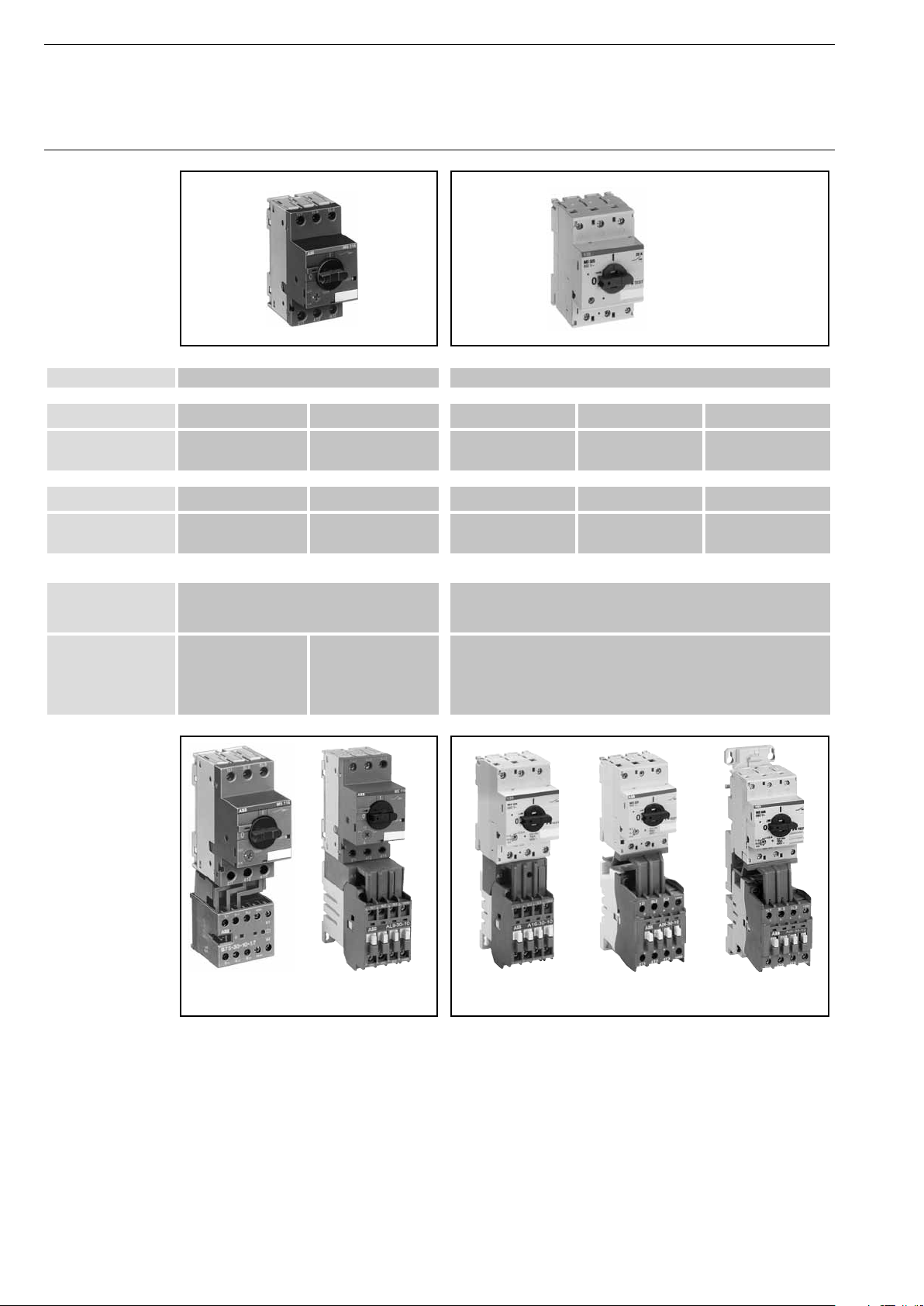
Starter Combinations
with Manual Motor Starters MSxxx
Overview
Manual Motor Starter
Direct adapter
Contactor,
AC controlled
Direct adapter
Contactor,
DC controlled
Further accessories
Aux.-contact
1NO/1NC
for front mounting
Phase busses
for MSS
Examples for Starter Combinations
MS116 up to 16 A MS325, MO325 up to 25 A
BEA7/116 BEA16/116 BEA7/325 BEA16/325
B6 B7 A9 A12 A16 B6 B7 A9 A12 A16
BEA7/116 BEA16/116AL BEA7/325 BEA16/325AL
BC6 BC7 AL9 AL12 AL16 BC6 BC7 AL9 AL12 AL16
HKF1-11 HKF-11
PS1-2-1 for 2 starters
PS1-3-1 for 3 starters
PS1-4-1 for 4 starters
PS1-5-1 for 5 starters
PS1-2-0 for 2 starters
PS1-3-0 for 3 starters
PS1-4-0 for 4 starters
PS1-5-0 for 5 starters
PS3-2-0 for 2 starters
PS3-3-0 for 3 starters
PS3-4-0 for 4 starters
PS3-5-0 for 5 starters
PS3-6-0 for 6 starters
BEA26/325
A26 A30 A40
BEA26/325AL
AL26 AL30 AL40
16
2CDC243013F0005
MS116 with B7 MS116 with AL16
2CDC243014F0005
MS325 with A16
2CDC 243 010 F0005
MS325 with A26
2CDC 243 011 F0005
MS325 with A26
at PM26-13
1SBC 591 653 F0304
Page 16
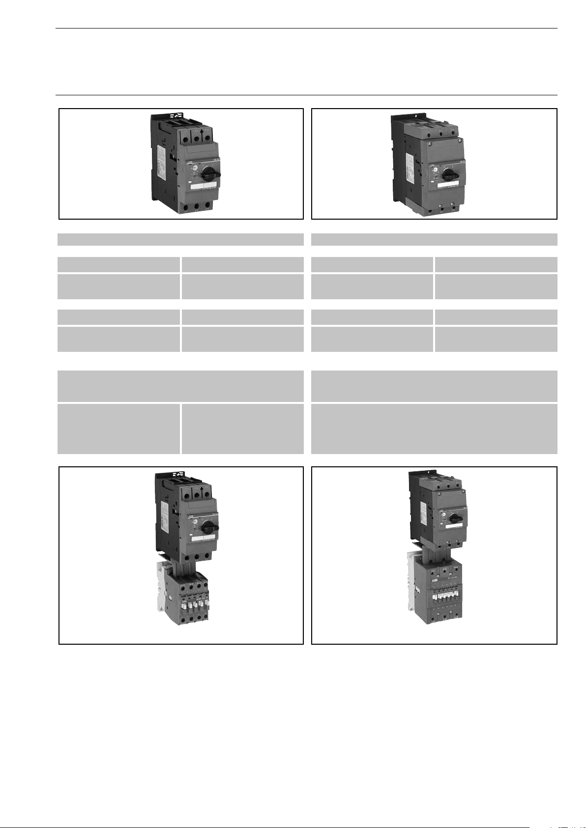
Starter Combinations
with Manual Motor Starters MSxxx
Overview
MS45x, MO450 up to 50 A MS49x, MO49x up to 100 A
BEA40/450 BEA50/450 BEA75/495 BEA16/325
A30 A40 A50 A50 A63 A75 A95 A110
- BEA50/450 BEA75/495 BEA110/495
AL30 AL40 AE50
HK4-11 H4F-11
PS4-2-0 for 2 starters
PS4-3-0 for 3 starters
PS4-4-0 for 4 starters
AF50
PS4-2-1 for 2 starters
PS4-3-1 for 3 starters
PS4-4-1 for 4 starters
AE50 AE63 AE75
AF50 AF63 AF75
AE95 AE110
AF95 AF110
MS450 with A40 MS495 with A110
17
Page 17
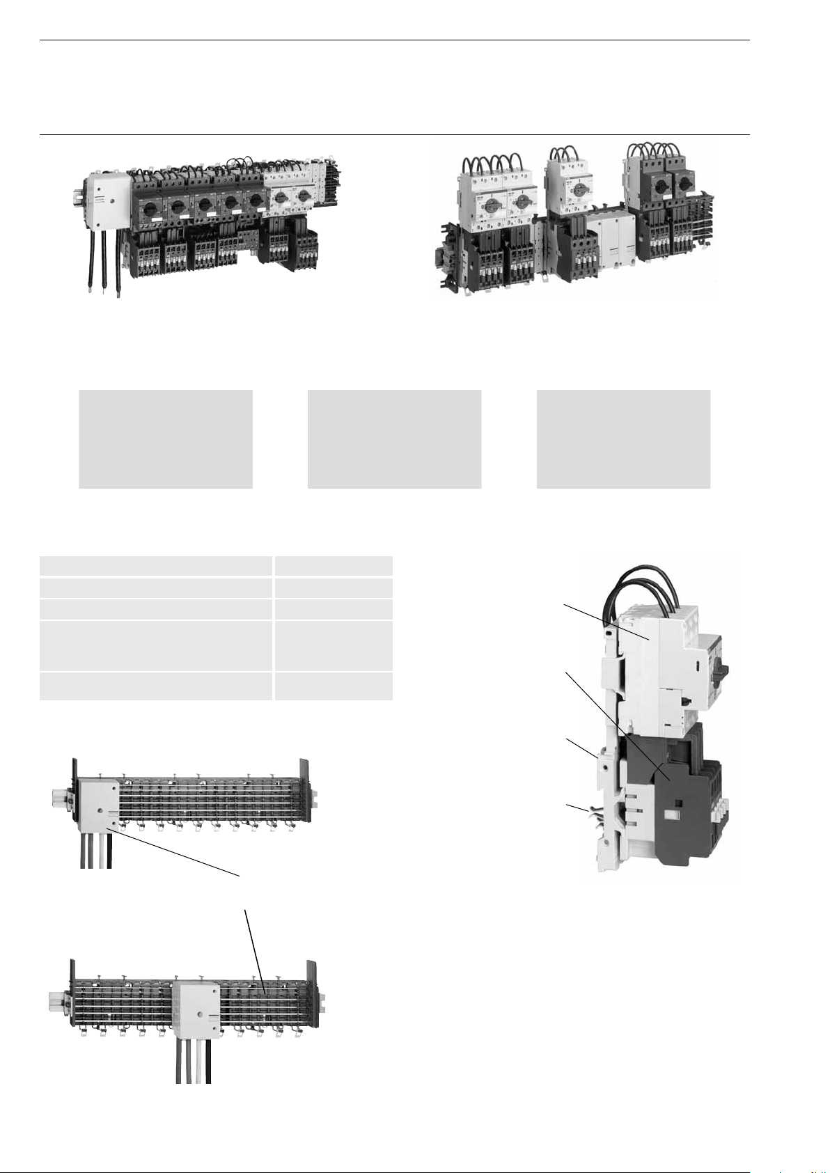
Busbar system smissline-S
For power distribution up to 200 A
Smissline-S is a powerful busbar system with quick and easy installation of protection devices as manual motor starters, starter combinations and MCB. This powerful system offers a lot of advantages for
industries regarding time savings. cost reduction, fl exibility, availability, safety and transparent installation.
Time and cost savings
• Quick installation
• Less cables / cable channels
• Reduce changing costs
• Quick trouble shooting
• Maintenance under power
Flexibility and availability
• Free of phase allocation
• Mounting in any position
• Quick replacement of devices
• Less stops in production
• Room reserves for backup
Technical Data
For DIN rail or wall-mounting
Mounting position: vertical, horizontal
Max. operating voltage: 690 V
Max. operating current:
supply on left or right: 100 A
supply in center: 200 A
Short circuit capacity: 50 kA
Customers benefi ts are in a fl exible and easy project planning. Room
& power reserves can be used if project and technical expansion is
necessary. Additional devices can be plugged in easily in this plug &
play starter concept. To form a system there are only few parts needed: Busbar kit, feeder block & starter combination.
Safety and transparency
• Less clamping points
• Less fi reload
• High power reserve
• Clear installation
• Touch proved
Manual motor starter
Contactor
supply on right or left: max. 100 A
supply in center: max. 200 A
18
Combi module for plug in
Plugs
SST40424
Feeder block
Busbar kit including busbars
SST40426
Page 18
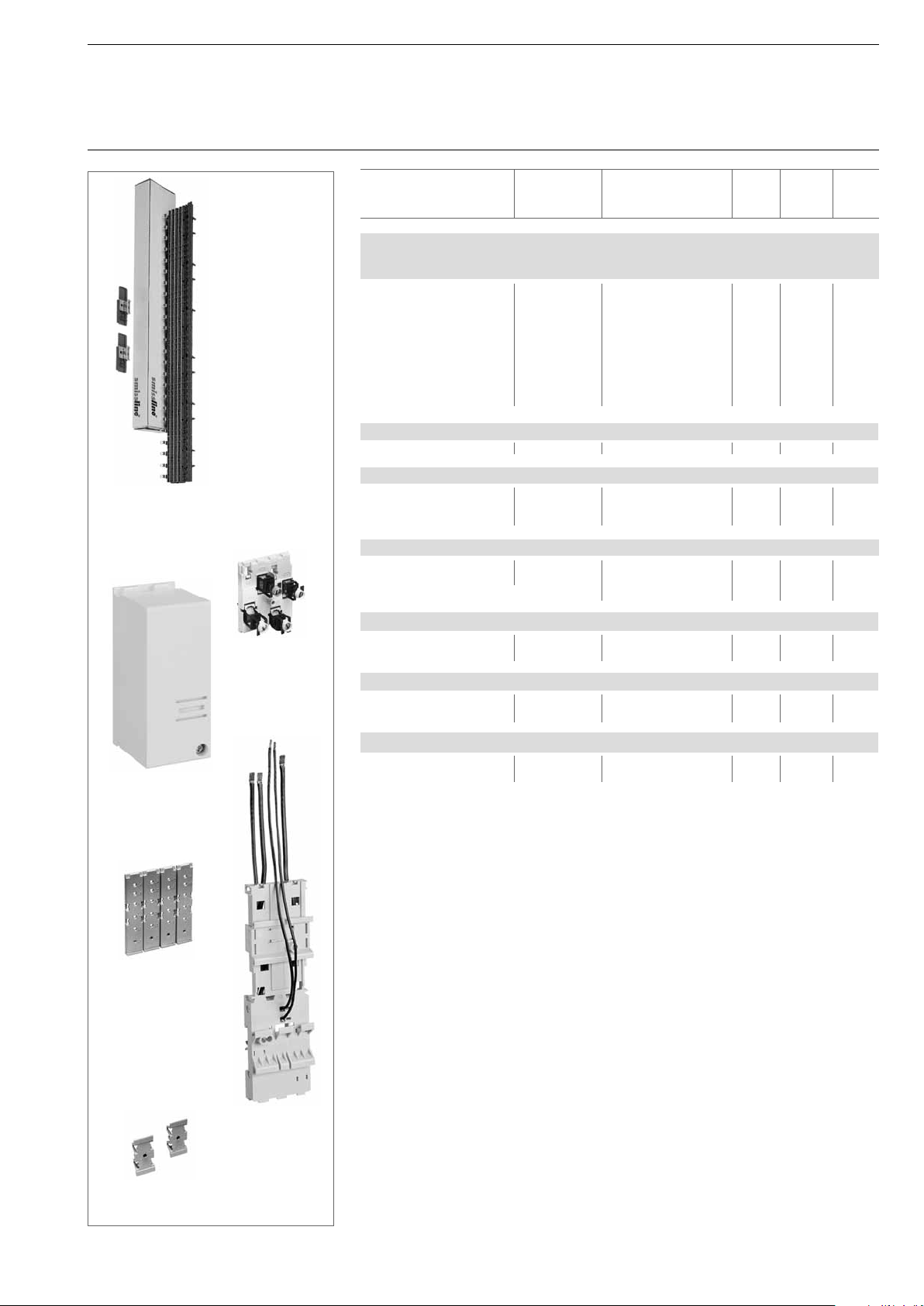
ZLS 756
Busbar module
incl. sockets,
busbars and
end pieces
SST 40277
Busbar system smissline-S for MS325
Manual Motor Starter for plug in
Design Type Order code Weight/ Packing Price
piece Unit
kg piece
Busbar System as a complete module in a package for plug and play
including plastic sockets, busbars for 3 phases L1, L2, L3 and end pieces
fi xed modules, ready for DIN rail mounting
Length: 393 mm 22 PLE ZLS 760 2CCF 016 420 R0001
429 mm 24 PLE ZLS 750 2CCF 015 346 R0002
537 mm 30 PLE ZLS 762 2CCF 016 422 R0003
573 mm 32 PLE ZLS 752 2CCF 015 348 R0004
685 mm 38 PLE ZLS 764 2CCF 016 424 R0005
717 mm 40 PLE ZLS 754 2CCF 015 350 R0002
861 mm 48 PLE ZLS 756 2CCF 015 352 R0003
1150 mm 64 PLE ZLS 766 2CCF 016 426 R0004
1438 mm 80 PLE ZLS 758 2CCF 015 354 R0005
Infeed block 160A with cover
3-phase block 4 PLE ZLS225 2CCF 015 197 R0014
Infeed Elements 200A with cover
Infeed Element Phase 1 2CCV 672 501 R0001
Infeed Element Phase 2 2CCV 672 502 R0001
Infeed Element Phase 3 2CCV 672 503 R0001
ZLS 100
ZLS 224/225
without cover
2CDC 241 019 F0004
SK 0120 B93
Busbar cover pieces for empty places
Busbar cover pieces ZLS 100 2CCF 002 762 R0001
for empty places
1 piece can cover 4 PLE - 1 PLE can be break down
SK 0197 B93
Combi modules wire top feed up to 32A
L1, L2, L3 top feed ZLS 8403LWT-S 2CCA 180 451 R0001
L1, L2, L3, N top feed ZLS 8403LNWT-S 2CCA 180 452 R0001
Combi modules wire bottom feed up to 32A
L1, L2, L3 bottom feed ZLS 8403LWB-S 2CCA 180 465 R0001
L1, L2, L3, N bottom feed
ZLS 8403LNWB-S
2CCA 180 462 R0001
Adapter plate ZMS915 for MS325 for plug in to the busbar system
Adapter plate for max. ZMS915 GHE 610 1002 R0030
415V, 20A
Single Adapter Plates up to 63 A to mount standard control gear and DIN Rail products
see smissline-S catalog.
ZLS 101
2CDC 241 014 F0004
SK 0121 B93
19
Page 19
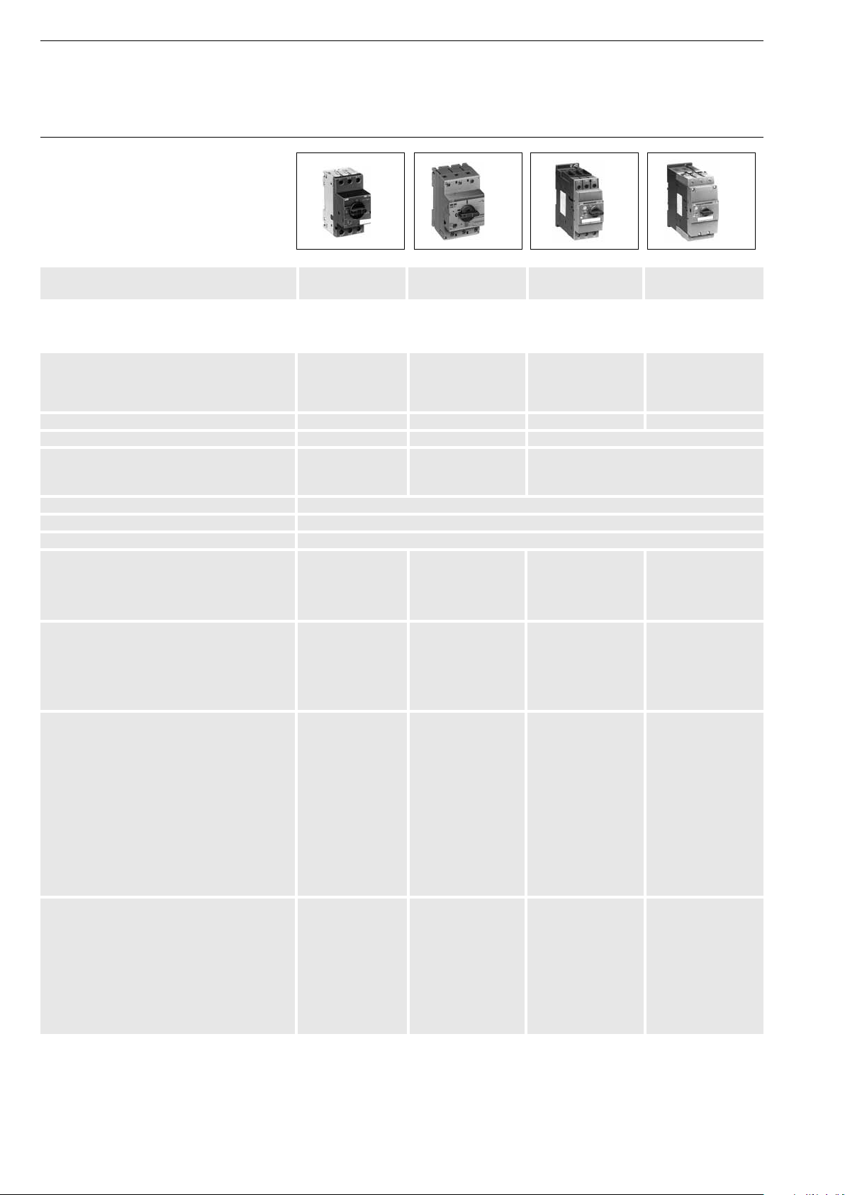
Manual Motor Starters Type Series MS
Technical data
SST11601
SST01497
SST02198
SST01898
Manual motor starter Type MS116 MS325; MO325 MS450/451; MO450 MS495/496/497;
MO495/496
General technical data
Standards: The devices comply with the major 947-1 947-1 947-1 947-1
international, European and national 947-2 947-2 947-2 947-2
regulations IEC 60../EN 60.. 947-4-1 947-4-1 947-4-1 947-4-1
947-5-1 947-5-1 947-5-1 947-5-1
Disconnector characteristics (to IEC/EN 60947-1) yes yes yes yes
Mechanical service life in operations 100.000 100.000 50.000
Permissible ambient temperature
- Operating temperature °C – 20... + 55/70 – 25 ... + 55/70 – 20 ... + 60/70
- Storage temperature °C – 50 ... + 80 – 50 ... + 80 – 50 ... + 80
Temperature compensation with
Mounting position any
Permissible altitude m 3000 3000 2000
Permissible resistance to vibrations
(IEC 68-2-6) Amplitude 5 g Amplitude 5 g
Permissible resistance to shocks
(IEC 68-2-27)
Mounting (mounting hardware not included in
scope of delivery)
Screw fi xing see accessories see accessories 2 x M5 2 x M5
Quick fastening to EN 50022 35 mm 35 mm 35 mm 35 mm,
on top-hat rail (15 mm high)
to EN 50023 – – – 75 mm
Electrical connection
of the main conductors (main circuits)
Type Screw terminal Box terminal Box terminal Box terminal
+ bus
Screw Pozidrive size 2 Pozidrive size 2 Pozidrive size 2 Internal hexagon
4 mm
Single-core 1 x mm
2 x mm
Stranded 1 x mm
2 x mm
Flexible 1 x mm
2 x mm
of the auxiliary conductors (auxiliary circuits)
Type Screw Screw Screw
terminal terminal terminal
Screw Pozidrive size 2 Pozidrive size 1 Pozidrive size 2
Single-core 1 x mm
2 x mm
Flexible 1 x mm
2 x mm
10-150 Hz 10-150 Hz on request on request
sinusoidal shock
25 g (11 ms) 15 g (11 ms) on request on request
2
2
2
2
2
2
2
2
2
2
1 ... 4 1 ... 10 0.75 ... 35 2.5 ... 70
1 ... 4 1 ... 4 0.75 ... 25 2.5 ... 50
1 ... 4 1 ... 10 0.75 ... 35 2.5 ... 70
1 ... 4 – 0.75 ... 25 2.5 ... 50
0.75 ... 2.5 1 ... 6 0.75 ... 25 2.5 ... 50
0.75 ... 2.5 – 0.75 ... 16 2.5 ... 35
1 ... 2.5 0.5 ... 2.5 0.5 ... 2.5
1 ... 2.5 0.5 ... 2.5 0.5 ... 2.5
0.75 ... 2.5 0.5 ... 2.5 0.5 ... 1.5
0.75 ... 2.5 0.5 ... 2.5 0.5 ... 1.5
Operating conditions up to 70° C on request
G-values refer to the mounting position subject to the highest shock sensitivity
Also applies to auxiliary switches HKF1 and undervoltage release UA1
For auxiliary switch HKF.. Pozidrive 2
Applies to auxiliary switches HK1 and SK1
20
Page 20

Manual Motor Starters Type Series MS
Technical data
Manual motor starter Type MS116 MS325; MO325 MS450/451; MO450 MS495/496/497;
MO495/496
General electrical data
Rated insulation voltage Ui
to EN 60947 V AC 690 690 690 690
to CSA / U
Rated operating voltage U
Rated impulse strength U
Rated continuous thermal current I
/ NEMA V AC 600 600 600 600
L
up to V 690 AC/440 DC 690 AC/440 DC 690 AC/440 DC 690 AC/440 DC
e
kV 6 6 6 6
imp
th
A 16 25 50 100
Rated frequency Hz 50/60
Rated current ranges I
(number of ranges) (12) (14) (7) (6)
e
Rated service short-circuit breaking capacity I
A 0.1 ... 16 0.1 ... 25 11 ... 50 28 ... 100
and max. permissible back-up fuses see pages 23 / 24.
cs
DC rated operating voltage
in the case of series connection
of 3 main circuits
(see wiring diagram, Page 25)
DC 1, 60 V A on request 25 50 100
DC 3, 60 V A on request 25 50 100
DC 5, 60 V A on request 25 50 100
Short circuit capacity for DC-rating on request
Auxiliary circuits
Load rating of the auxiliary circuits
Minimum load at: 24 V DC mA 5 mA at 17 VDC 5 5 mA at 17 VDC
12 V DC mA – 10 –
Auxiliary contact for front mounting
230V, 1.5 A 120V, 3.0 A 230V, 3.0 A
230V, 2.0 A
DC13 24V, 1.0 A 24V, 2.0 A 24V, 1.0 A
60V, 0.7 A 60V, 2.5 A 48V, 0.3 A
110 V, 0.3 A 110 V, 0.6 A 60 V, 0.15 A
220 V, 0.1 A 220 V, 0.25 A
Auxiliary and signal contact
230V, 4.0 A 120V, 3.0 A 230V, 4.0 A
400 V, 3.0 A 230V, 2.0 A 400 V, 3.0 A
DC13 24V, 2.0 A 24V, 2.0 A 24V, 1.0 A
110 V, 0.5 A 60V, 2.5 A 110 V, 0.5 A
220 V, 0.25 A 110 V, 0.6 A 220 V, 0.25 A
220 V, 0.25 A
Correction factors for other frequencies on request
AC15 24V, 3.0 A 24V, 4.0 A 24V, 4.0 A
AC15 24V, 6.0 A 24V, 4.0 A 24V, 6.0 A
21
Page 21

Manual Motor Starters Type Series MS
Technical data
Manual motor starter Type MS116 MS325; MO325 MS450/451; MO450 MS495/496/497;
MO495/496
Release
Device for phase failure protection with
Electromagnetic trips
Response value set ex-works 7.8 ... 11.7 I
9.2 ... 13.8 In 9 ... 14 In
10.0 ... 15.0 I
12.0 ... 18.0 In
Undervoltage release
Pick-up value % of U
Drop-out value % of U
Power consumption Pick-up VA 9.0 0.9 20.2
c
c
> 85 > 85 > 85
35 ... 75 35 ... 75 35 ... 70
Hold VA 3.0 0.9 7.2
Open-circuit shunt release
Pick-up value % of U
Relative duty % ED 100 – 100, max. 5 sec
c
> 70 > 85 > 70
Power consumption Pick-up VA 9.0 110-240V: 13-61 on request
Hold VA 3.0 – on request
7.5 ... 12 In
n
10 ... 15 In
n
12.5 ... 17.5 In
10.4 In ... 15.6 I
n
Internal resistance values
Setting ranges Resistance per phase in Ω resp. MS4.. in mΩ
A
from to MS116 MS325 MS450 MS451 MS495/MS497 MS496
0.1 ... 0.16 66 71.1 – – – –
0.16 ... 0.25 25.5 27.1 – – – –
0.25 ... 0.4 10.38 12.3 – – – –
0.4 ... 0.63 4.36 5.17 – – – –
0.63 ... 1.0 1.602 2.09 – – – –
1.0 ... 1.6 0.645 0.805 – – – –
1.6 ... 2.5 0.2795 0.34 – – – –
2.5 ... 4.0 0.1035 0.141 – – – –
4.0 ... 6.3 0.0433 0.051 – – – –
6.3 ... 9.0 – 0.0224 – – – –
6.3 ... 10.0 0.0217 – – – – –
8,0 ... 12,0 0.0148 – – – – –
9.0 ... 12.5 – 0.0122 – – – –
10.0 ... 16.0 0.0088 – – – – –
11.0 ... 16.0 – – 13.3 13.8 17.3 –
12.5 ... 16.0 – 0.0081 – – – –
14.0 ... 20.0 – – 8.74 8.74 11.3 –
16.0 ... 20.0 – 0.0048 – – – –
18.0 ... 25.0 – – 5.43 5.83 7.11 –
20.0 ... 25.0 – 0.0035 – – – –
22.0 ... 32.0 – – 3.60 4.10 4.75 –
28.0 ... 40.0 – – 2.56 2.90 3.28 3.28
36.0 ... 45.0 – – 1.80 2.20 – –
36.5 ... 50.0 – – – – 2.24 2.52
40.0 ... 50.0 – – 1.46 1.82 – –
45.0 ... 63.0 – – – – 1.40 1.40
57.0 ... 75.0 – – – – 0.95 1.00
70.0 ... 90.0 – – – – 0.60 0.63
80.0 ... 100.0 – – – – 0.54 0.57
Current ranges 0.16 to 0.63 A
Current ranges 1 to 2.5 A
Current ranges 4 to 6.3 A
Current ranges 9 to 25 A
24-60 V: 14.4-90 VA
Current ranges 10 to 16 A
Relative duty at voltages, R1001: 20 to 70 V
R1002: 70 to 190 V
R1003: 190 to 330 V
R1004: 330 to 500 V at 50/60 Hz or DC
22
Page 22
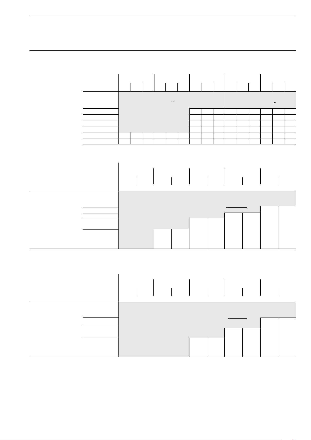
Manual Motor Starters Type Series MS
Technical data
Short-circuit protection MS116, setting ranges, short-circuit strength and max. back-up fuses
Maximum rated current of the short-circuit fuses if Icc > Ics
at at at at at
from to 230 V AC 400 V AC 440 V AC 500 V AC 690 VAC
I
A A kA kA A kA kA A kA kA A kA kA A kA kA A
Setting ranges 0.1 ... 0.16
to
1.0 ... 1.6
1.6 ... 2.5 10 10 25 10 10 25 5 5 25
2.5 ... 4.0 6 6 25 6 6 25 2 2 25
4.0 ... 6.3 6 6 63 6 6 63 2 2 40
6.3 ... 10.0 6 6 63 6 6 63 2 2 50
8.0 ... 12.0 25 25 80 25 25 80 6 6 63 6 6 63 2 2 50
10.0 ... 16.0 16 16 80 16 16 80 4 4 63 4 4 63 2 2 63
Short-circuit protection MS325 / MO325, setting ranges, short-circuit strength and max. back-up fuses
Maximum rated current of the short-circuit fuses if Icc > Ics
at at at at at
from to 230 V AC 400 V AC 440 V AC 500 V AC 690 VAC
I
kA A kA A kA A kA A kA A
A A Fuse types: Diazed, l.v.h.b.c., utilisation categories: gL, aM (VDE), gL/gG (IEC)
Setting ranges 0.1 ... 0.16
to
1.0 ... 1.6
1.6 ... 2.5 40 25
2.5 ... 4.0 60 35 / 40 10 40
4.0 ... 6.3 70 50 40 50 7 40
6.3 ... 9.0 50 80 30 80 5 50
9.0 ... 12.5 75 80 45 80 27 80 4.5 50
12.5 ... 16.0 60 100 40 100 25 100 4 50
16.0 ... 20.0 55 100 35 100 22 100 3.5 50
20.0 ... 25.0 50 125 30 125 20 125 3 50
Ics gL, gG Icu Ics gL, gG Icu Ics gL, gG Icu Ics gL, gG Icu Ics gL, gG
cu
Short-circuit proof
up to Icc = 50 kA
gL, aM Ics gL, aM Ics gL, aM Ics gL, aM Ics gL, aM
cs
Short-circuit proof
up to Icc = 30 kA
Short-circuit proof
No back-up fuse required up to Icc = 100 kA
Short-circuit protection MS325 / MO325, setting ranges, short-circuit strength and max. back-up fuses
Maximum rated current of the short-circuit fuses if Icc > Ics
at at at at at
from to 230 V AC 400 V AC 440 V AC 500 V AC 690 VAC
I
kA A kA A kA A kA A kA A
A A Fuse types: Diazed, l.v.h.b.c., utilisation categories: gL, aM (VDE), gL/gG (IEC)
Setting ranges 0.1 ... 0.16
to
1.0 ... 1.6
1.6 ... 2.5 40 25
2.5 ... 4.0 10 40
4.0 ... 6.3 40 50 7 40
6.3 ... 9.0 30 80 5 50
9.0 ... 12.5 45 80 27 80 4.5 50
12.5 ... 16.0 40 100 25 100 4 50
16.0 ... 20.0 35 100 22 100 3.5 50
20.0 ... 25.0 30 125 20 125 3 50
Ics = Rated service short-circuit breaking capacity, Icu = Rated ultimate short-circuit capacity, Icc = Prospective short-circuit current at installation location.
= Icu in the case of MS325 and MS116!
I
cs
gL, aM Ics gL, aM Ics gL, aM Ics gL, aM Ics gL, aM
cs
Short-circuit proof
No back-up fuse required up to
Icc = 50 kA
23
Page 23
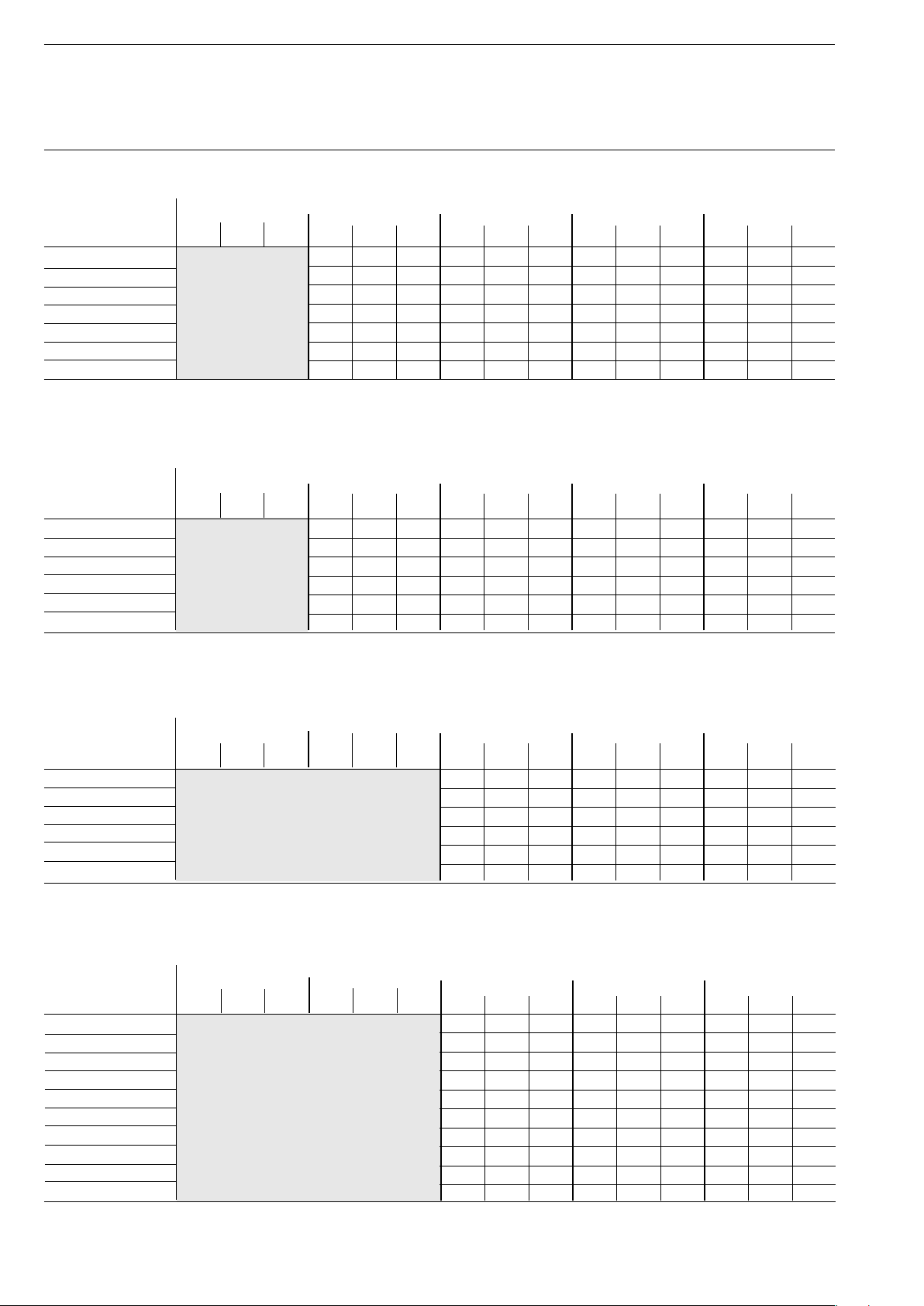
Manual Motor Starters Type Series MS
Technical data
Short-circuit protection MS450 / MS451 / MO450, setting ranges, short-circuit strength and max. back-up fuses
Maximum rated current of the short-circuit fuses if I
Setting ranges 230 V AC 400 V AC 440 V AC 500 V AC 690 V AC
I
in A in kA in kA in A in kA in kA in A in kA in kA in A in kA in kA in A in kA in kA in A
cs
11 ... 16 25 50 100 25 50 100 6 12 63 3 5 63
14 ... 20 25 50 125 25 50 100 6 12 80 3 5 63
18 ... 25 25 50 125 15 30 100 6 12 80 3 5 63
22 ... 32 25 50 125 15 30 125 5 10 100 2 4 63
Short-circuit-proof
No back-up fuse required
28 ... 40 25 50 160 15 30 125 5 10 100 2 4 63
36 ... 45 25 50 160 15 30 125 5 10 100 2 4 63
36 ... 50 25 50 160 15 30 125 5 10 100 2 4 80
Short-circuit protection MS495 / MO495, setting ranges, short-circuit strength and max. back-up fuses
Maximum rated current of the short-circuit fuses if I
Setting ranges 230 V AC 400 V AC 440 V AC 500 V AC 690 V AC
I
in A in kA in kA in A in kA in kA in A in kA in kA in A in kA in kA in A in kA in kA in A
28 ... 40 25 50 125 20 40 125 6 12 100 6 3 63
36 ... 50 25 50 125 20 40 125 6 12 100 6 3 80
45 ... 63 25 50 160 20 40 160 6 12 100 6 3 80
57 ... 75 25 50 160 20 40 160 4 8 125 5 3 100
70 ... 90 25 50 160 20 40 160 4 8 125 5 3 125
80 ... 100 25 50 160 20 40 160 4 8 125 5 3 125
cs
Short-circuit-proof
No back-up fuse required
I
up to I
up to I
cu
= 100kA
cc
I
cu
= 100kA
cc
gL,gG I
gL,gG I
I
I
cu
cu
gL,gG I
gL,gG I
cs
cs
I
I
cu
cu
gL,gG I
gL,gG I
cs
cs
cs
cs
> Icu
cu
> Icu
cu
I
I
cu
cu
gL,gG I
gL,gG I
I
cs
cs
gL,gG
cu
I
gL,gG
cu
Short-circuit protection MS496 / MO496, setting ranges, short-circuit strength and max. back-up fuses
Maximum rated current of the short-circuit fuses if I
Setting ranges 230 V AC 400 V AC 440 V AC 500 V AC 690 V AC
I
in A in kA in kA in A in kA in kA in A in kA in kA in A in kA in kA in A in kA in kA in A
28 ... 40 25 50 160 9 18 160 6 12 80
36 ... 50 25 50 160 7.5 15 160 5 10 100
45 ... 63 25 50 200 7.5 15 160 4 7.5 100
57 ... 75 25 50 200 5 10 160 3 6 125
70 ... 90 25 50 200 5 10 160 3 6 160
80 ... 100 25 50 200 5 10 160 3 6 160
I
cs
gL,gG I
cu
Short-circuit-proof
No back-up fuse required up to
= 100kA
I
cc
I
cu
gL,gG I
cs
I
cu
gL,gG I
cs
cu
cs
> Icu
I
cu
gL,gG I
I
cs
gL,gG
cu
Short-circuit protection MS497, setting ranges, short-circuit strength and max. back-up fuses
Maximum rated current of the short-circuit fuses if Icu > Icu
Setting ranges 230 V AC 400 V AC 440 V AC 500 V AC 690 V AC
I
in A in kA in kA in A in kA in kA in A in kA in kA in A in kA in kA in A in kA in kA in A
11 .. 16 25 50 100 15 30 80 7 15 63
14 ... 20 25 50 100 15 30 80 7 15 63
18 ... 25 25 50 100 15 30 80 7 15 63
22 ... 32 25 50 125 11 22 100 7 15 63
28 ... 40 25 50 160 9 18 160 6 12 80
36 ... 50 25 50 160 7.5 15 160 5 10 100
45 ... 63 25 50 200 7.5 15 160 4 7.5 100
57 ... 75 25 50 200 5 10 160 3 6 125
70 ... 90 25 50 200 5 10 160 3 6 160
80 .. 100 25 50 200 5 10 160 3 6 160
I
= Rated service short-circuit breaking capacity, Icu = Rated ultimate short-circuit breaking capacity Icc = pProspective short-circuit current at installation location.
cs
I
cs
gL,gG I
cu
Short-circuit-proof
No back-up fuse required up to
I
cc
= 100kA
I
cu
gL,gG I
cs
I
cu
gL,gG I
cs
I
cu
gL,gG I
cs
I
cs
gL,gG
cu
24
Page 24
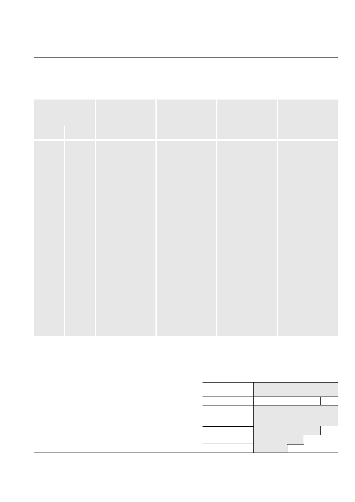
Manual Motor Starters Type Series MS
Technical data
Coordination acc. IEC / EN 60947-4-1
The following table lists the combinations of motor protection switches and contactors according to assignment type 2 in compliance with
IEC / EN 60947-4-1
Assignment type 2, 400 V - 50 Hz, 50 kA, normal start
Motor output AC-3 Motor protecting Setting range Contactor Maximum current
and design current three switch Type permitted for the
phase cage motor type combination
1500 rp/min.
380/400 V
P
/kW Ie/A A ... A A
e
0.06 0.22 MS325-0.25 0.16 ... 0.25 A9 0.25
0.09 0.33 MS325-0.4 0.25 ... 0.4 A9 0.4
0.12 0.42 MS325-0.63 0.40 ... 0.63 A9 0.63
0.18 0.72 MS325-1 0.63 ... 1 A9 1
0.25 0.83 MS325-1 0.63 ... 1 A9 1
0.37 1.2 MS325-1.6 1 ... 1,6 A9 1.6
0.55 1.5 MS325-1.6 1 ... 1.6 A9 1.6
0.75 2 MS325-2.5 1.6 ... 2.5 A9 2.5
1.1 2.6 MS325-4 2.5 ... 4 A9 4
1.5 3.5 MS325-4 2.5 ... 4 A12 4
2.2 5 MS325-6.3 4 ... 6.3 A12 6.3
3 6.6 MS325-9 6.3 ... 9 A26 9
4 8.5 MS325-9 6.3 ... 9 A26 9
5.5 11.5 MS325-12.5 9 ... 12.5 A26 12.5
7.5 15.5 MS325-16 12.5 ... 16 A26 16
MS450-20 14 ... 20 A26 16
9 18.3 MS325-20 16 ... 20 A26 20
11 22 MS3265-25 20 ... 25 A30 25
MS450-25 18 ... 25 A30 25
15 30 MS450-32 22 ... 32 A30 30
18.5 37 MS450-40 28 ... 40 A40 40
22 44 MS450-50 40 ... 50 A50 50
30 60 MS495-63 45 ... 63 A63 63
37 72 MS495-75 57 ... 75 A95 75
45 85 MS495-90 70 ... 90 A95 90
55 98 MS495-100 80 ... 100 A110 100
Further coordination tables on request
2
Forward current integrals (lt
Peak forward current curves on request
Reliable line protection
Manual motor min. protected conductor cross section
Protection of PVC-insulated lines
starter type at 380 / 415 V AC, Cu mm
against thermal overload in the event of short circuit:
MS325 4 2.5 1.5 1.0 0.75
In compliance with VDE 0100 section 430 and 523, cables
0,16
to
and lines must be protected against overheating and short circuit.
6
The table opposite indicates which conductor cross-section are safely
10
protected by motor protection switches in the event of short circuit.
20
25
curves) on request
2
25
Page 25
Manual Motor Starters Type Series MS
Technical data
Times to trip
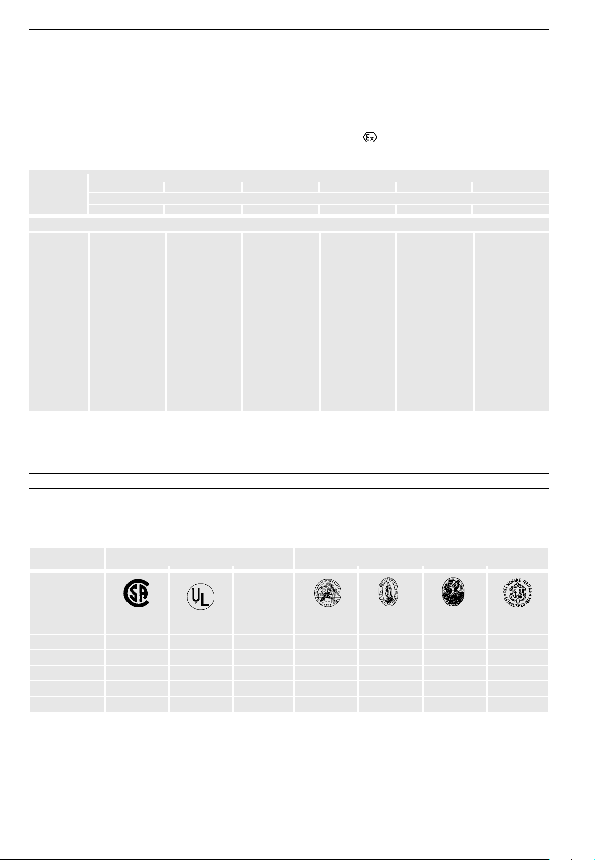
Selection table for suitability of the motor protection switches for motors of enclosure e
Time to trip of the motor protection switches as a function of a multiple of the setting current (tolerance ± 20 % of the time to trip).
PTB approvals, see below.
Setting range Time to trip of the motor protection switches at
of the manual 3 4 5 6 7.2 8
motor starter times the setting current, 3-pole, starting from cold state.
A A s s s s s s
Manual motor starter, Type MS325
0.1 ... 0.16 15 9 6.5 4.8 3.7 3.2
0.16 ... 0.25 16 10 6.8 5.2 4 3.6
0.25 ... 0.4 16 9.7 6.5 5 3.8 3.3
0.4 ... 0.63 17 10.2 7.3 5.7 4.4 3.9
0.63 ... 1.0 17.5 10.2 7.2 5.5 4.2 3.8
1.0 ... 1.6 17 10 7.1 5.6 4.4 4
1.6 ... 2.5 18 10.3 7.5 5.9 4.7 4.2
2.5 ... 4.0 18.4 11.5 8.1 6.4 5 4.6
4.0 ... 6.3 19 12 8.5 6.7 5.3 4.9
6.3 ... 9.0 18.2 11.5 7.9 6 4.5 3.8
9.0 ... 12.5 19 11.5 8 6 4.6 4
12.5 ... 16 19.5 11.5 7.5 5.4 4 3.3
16 ... 20 20 11.5 7.8 5.7 4,2 3.5
20 ... 25 20 10.4 7 5 3.7 3.2
Ident-numbers
of manual motor starters for motors with EEx e-Protection:
Type Ident-No.
MS325 3.53 - 1357/94 National Institute for Standards and Technology
MS450, MS495, MS497 Ex - 99.Y.74976 KEMA
Approvals and certifi cates
Device-Type Approvals, certifi cates Ship’s classifi cation societies
Test mark
EEx e
Abbreviation CSA ATEX GL LRS BV DNV
Validity Canada USA Germany Great Britain France Norway
MS116
MS325
MS450
MS495
MS497
Other approvals CCC/CB/GOST etc. on request
Approval for standard available
Approval process ongoing
26
Page 26
Manual Motor Starters Type Series MS
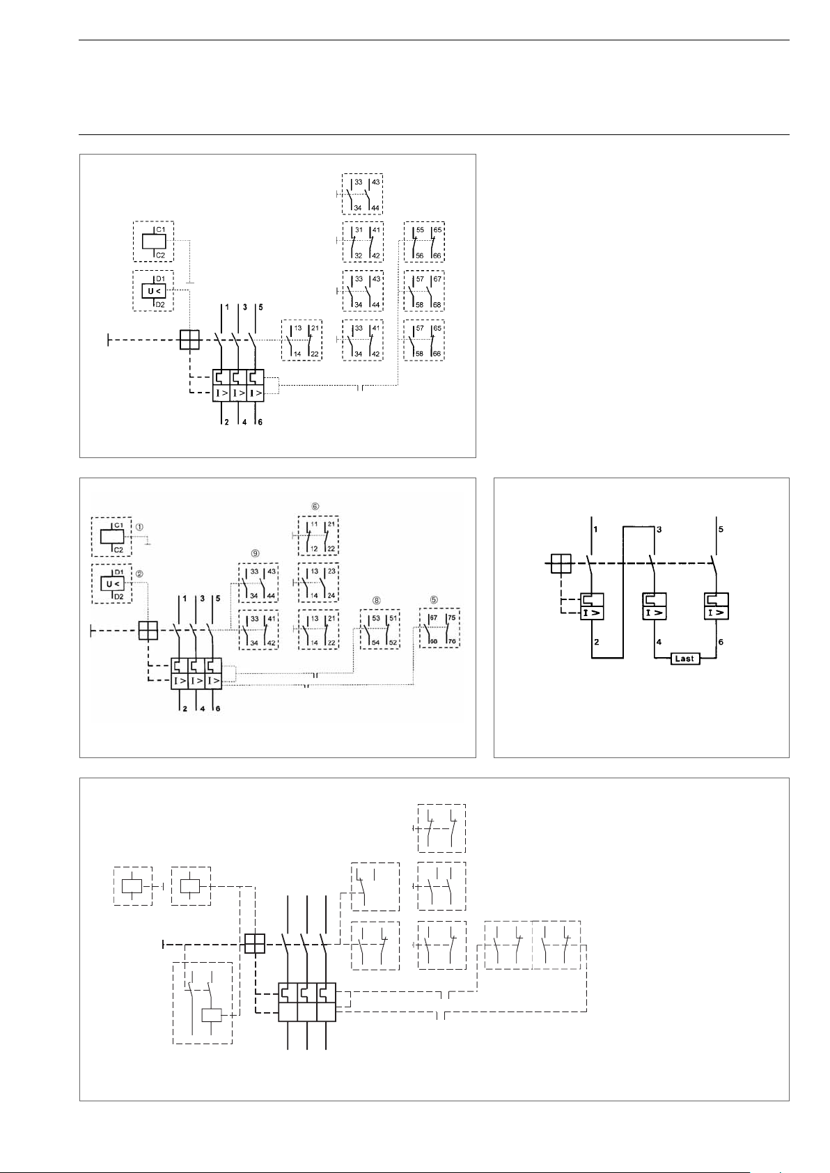
Wiring diagrams
Manual motor starter MS116 with accessories
Caption
Open-circuit shunt release
Undervoltage release
Undervoltage release with leading auxiliary switch 2 SV
Alarm switch for short-circuits
Auxiliary switch blocks for lateral attachment
Tripped alarm switch block (signalling contact)
Auxiliary switches which can be plugged on at the front
Alarm switch for short-circuits and general tripping
Manual motor starter MS325 with accessories
C1
C2
U <
D1
D2
07 D1
U <
08
1
I >
I >
D2
2
ABB 85 6976
Manual motor starter
for switching direct current and
single-phase alternating current
41
31
42
12
14
3
5
11
13 21
14 22
I >
4
6
32
434433
34
41
33
42
34
57 65
58 66
77 85
78 86
SST 212 98
Manual motor starter MS4xx
27
Page 27
Manual Motor Starter MS116
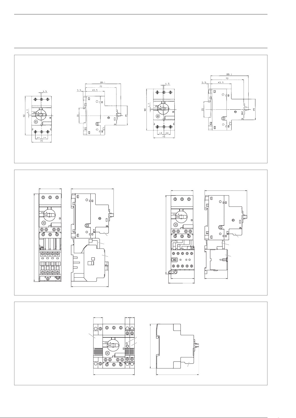
Accessories
Dimension diagrams
Manual motor starter MS116
Manual motor starter MS116 mounted with contactor A9...A16
45
85,6
MS116 with aux. contact HKF 1 for front mounting
SST007-00
Manual motor starter MS116 mounted with mini contactor B6/7
45
85,6
SST 006-00
177
75
HKF1-11
BEA16/116
A9 ... A16
Manual motor starter MS116 mounted with UA1.../SK1.../HK1.../HKF1-11
18
UA1-...
81
9
9
SK1-...
HK1-...
159
HKF1-11
BEA7/116
B6 / B7
47,5
52
90
HKF1-11
85,6
47
Dimension in mm
28
Page 28
Manual Motor Starters MS325
Accessories
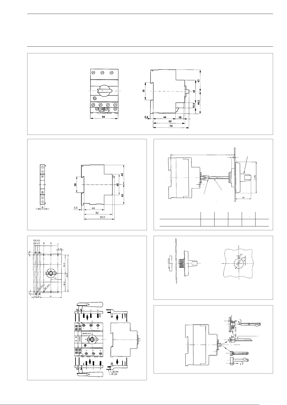
Dimension diagrams
Manual motor starter MS325 with aux. contact HKF for front mounting
SST 008-00
Signal contact SK
Auxiliary switch HK
Drilling plan
Printadapter PA25
SST 105 92 M
Switch cubicle mounting kit
mounting depth
driver
axis
Handle
Mounting depth mm 90 137 157 182 232
Axial length mm 32 85 105 130 180
SST 214 98
Outer twist knobs
Drilling plan
SST 215 98
SST 213 98
SST 201 99
Driver and spindles
SST 216 98
driver
Axis 85...180 mm
driver spindle 32 mm
Dimension in mm
29
Page 29
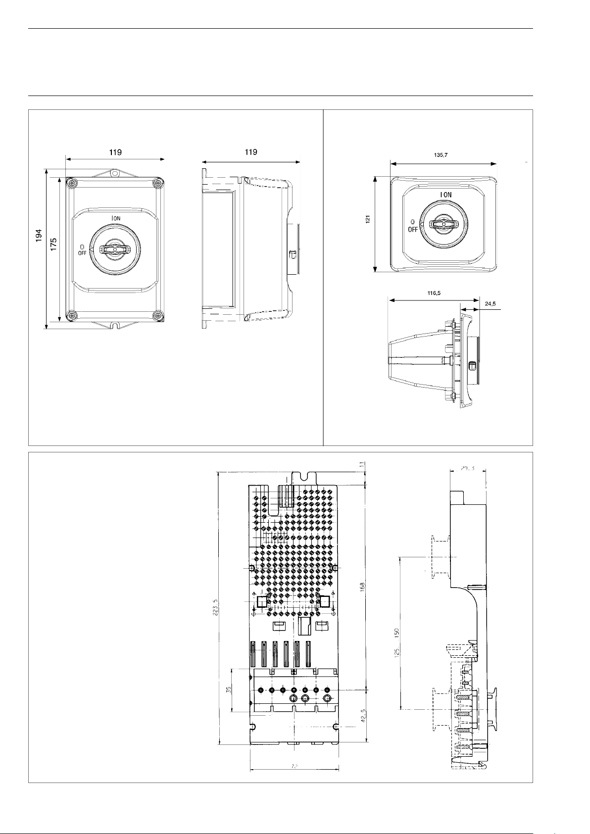
Manual Motor Starters MS325
Accessories
Dimension diagrams
Housing IP65
height
total height
width
Door Mounting Kit
depth
129
95
Mounting plate
starter combination for plug into
busbar system smissline-S
Dimensions in mm
30
Page 30
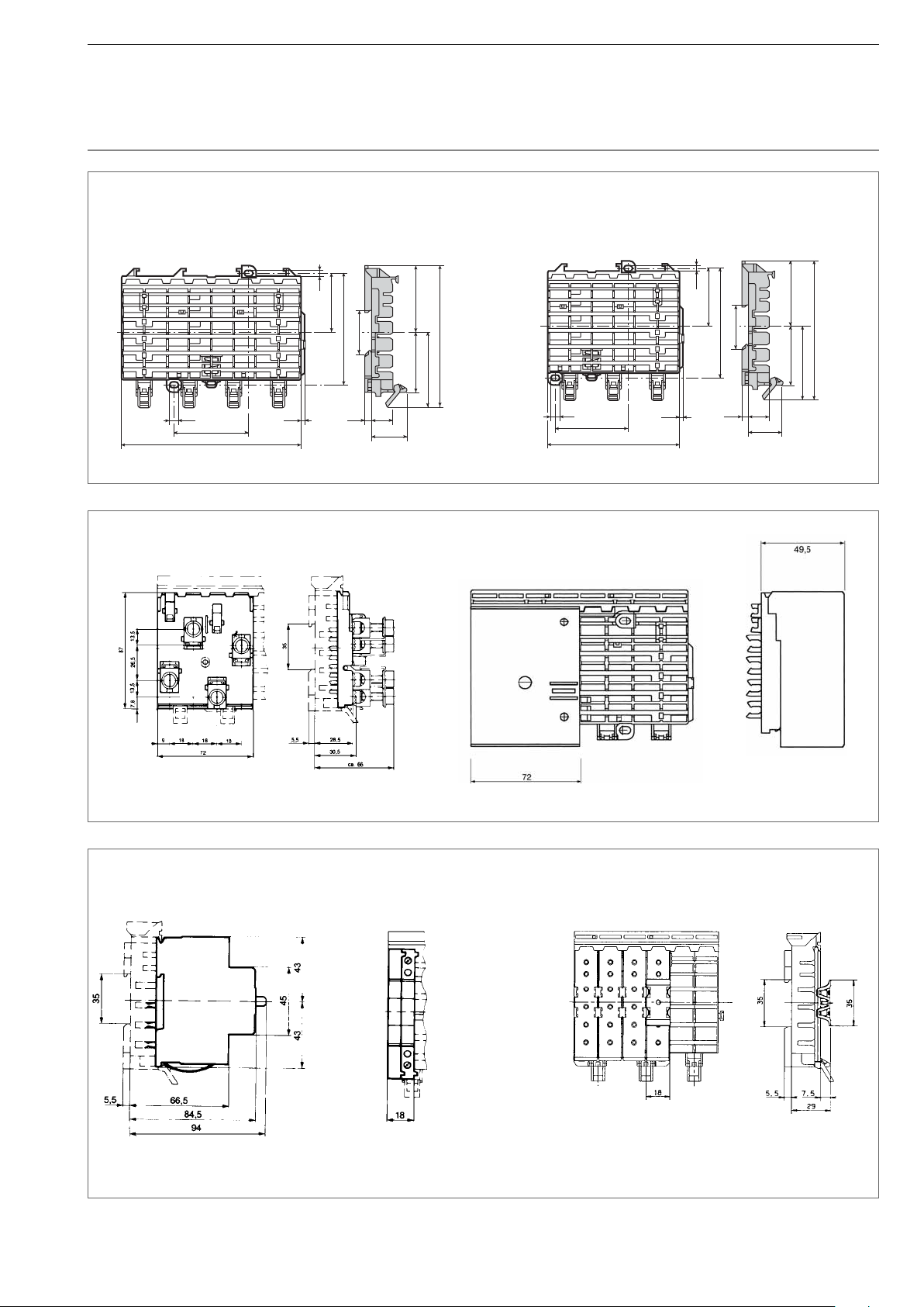
Busbar system smissline-S
Z20118
Socket ZLS 808 8 PLE
7.3
60
144
Power infeed block ZLS 224 4 PLE
Socket ZLS 806 6 PLE
4.5
47.5
35
90
3.5
5.4
53.5
114
61
48.8
17
28.6
Z20117.eps
7.3
60
108
4.5
47.5
35
90
3.5
5.4
53.5
114
61
48.8
17
28.6
Z20118.eps
Motor protection switch MS325 3 PLE
SK 0259 Z 93
SK 0263 Z 93
Auxiliary switch block HK
with empty housing ZLS 930
1 PLE
SK 0260 Z93
Busbar cover ZLS 100
with adapter ZLS 101
ZA
ZC
SK 0251 Z 93
Dimensions in mm
31
Page 31
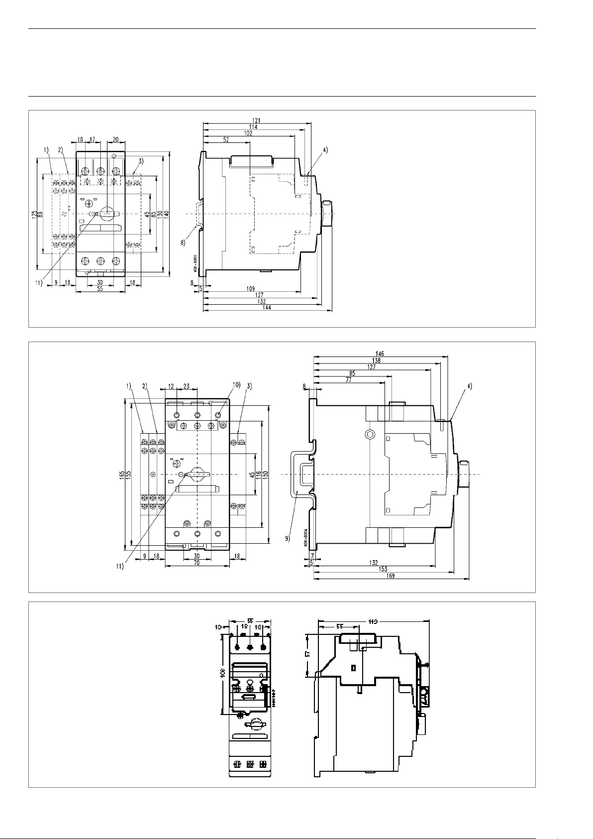
Motor manual starter MS45x
Manual Motor Starters MS45x / MS49x
Dimension diagrams
➋ Auxiliary switch block HKS4
➧ Pilot swich SK4
➥ Open-circuit shunt release/undervoltage release
AA4, UA4, UA4-HK
➌ Auxiliary switch HK4
Top-hat rail 35 mm to DIN EN 50022
➩ Top-hat rail 35 mm, 15 mm high
to DIN EN 50022
or Top-hat rail 75 mm to DIN EN 50023
Switch knob lockable in zero position with
bracket diameter 5 mm
SST 9003
Motor manual starter MS49x
MS45x with disconnector module TB450
SST 9004
32
SST 8193
Page 32
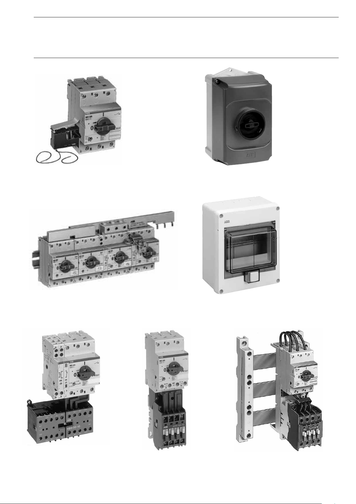
Manual Motor Starter MS325
Combinations with Accessories
SST02297
MS325
with undervoltage release UAF
MS325 with auxiliary switch HK
cross-wired with phase buses and power infeed block
Insulating
enclosure IP65
SST02597
ST01601
QES6/3N
ST02401
MS325 + HK + SK with
compact reversing contactor VB6
ST03201
MS325 + HKF with contactor A16
SST09698
MS325 with contactor A26
on busbar adapter SA11
33
Page 33
Manual Motor Starters Type MS
Combinations with Accessories
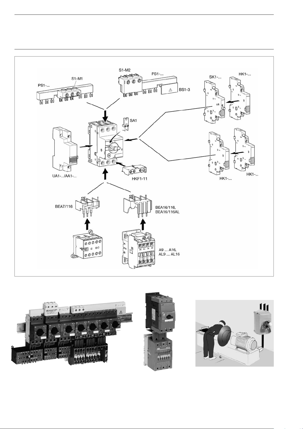
MS116 cross wired via phase busses
and power infeed blocks
34
MS495 with A95
connected via BEA 110/495
Manual Motor Starter Application: Switching on/off, Disconnection and locking
for service, Motorprotection
Page 34
Various Motor Starter combinations
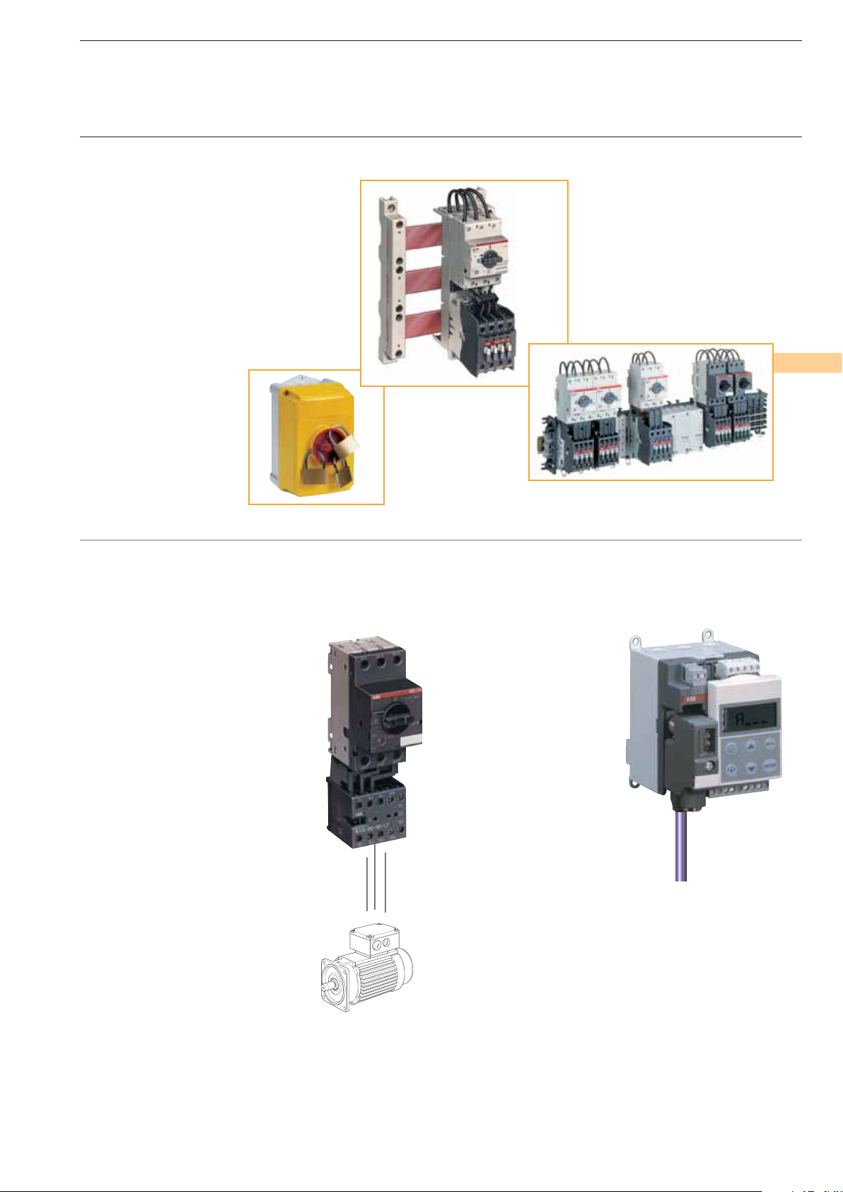
The manual motor starters from ABB are designed to be easily coordinated with various other components from ABB
to build a motor starter combination.
These combinations include for example
the A-Series contactors from ABB,
as well as other contactors like an
operating mechanism or mini-contactors Series “B”.
Together with the manual motor starters
MS116, MS325, MS450 and MS495 these
ABB components form coordinated starter
combinations for a large variety of applications.
Such a modular philosophy
brings endusers an
emproved service and
faster reactions
in operating systems.
Starter solution for plug-in
DOL Starters
A unit MS116/325 can be clipped, forming an automatically connected motor
starter combination.
Fast front connection, compact dimensions and a robust design are only the
most obvious advantages of ABB’s
motor starters.
Seperate gear concept
Individual devices for single wiring.
Manual motor starter and contactor
can be wired according to customer
demands.
Universal Motor Controller UMC22-FBP
The new FBP (FieldBusPlug)
product family is a communication device range of switching
and automation components
which can be combined easily
with standard fi eldbus systems.
35
Page 35
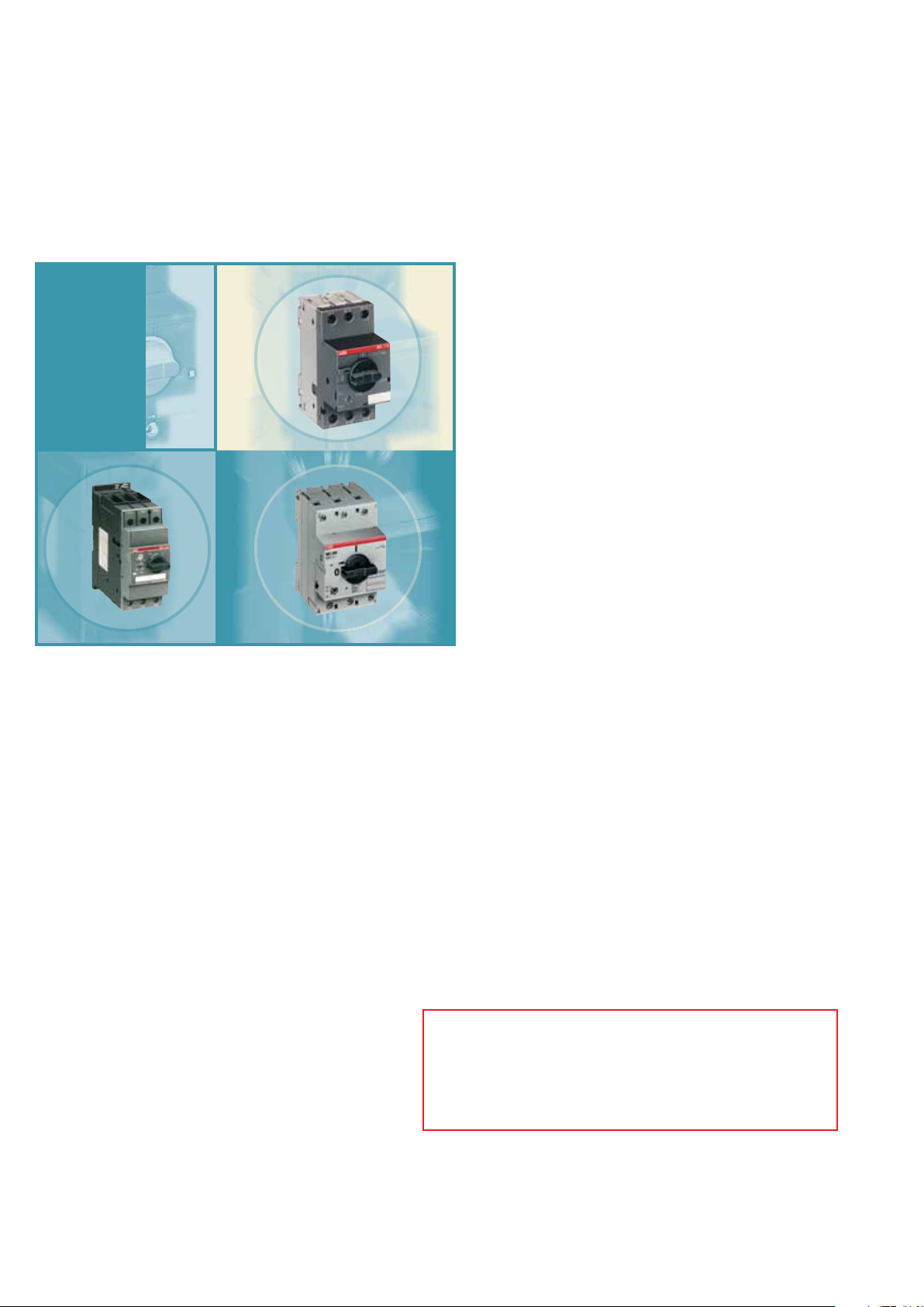
Manual Motor Starters
MS116, MS325, MS4xx
ABB
ABB STOTZ-KONTAKT GmbH
P. O. Box 10 16 80
D-69006 Heidelberg
Telephone: ++49 62 21 / 701-0
Telefax: ++49 62 21 / 701-723
http://www.abb.de/stotzkontakt
36
ABB Global Contact Directory
The ABB Contact Directory
helps you fi nd local contacts for ABB products in your country.
Please select the relevant product group from the dropdown
menu to the right or from the page.
(http://www.abb.com/contacts/)
Publication No.: 2CDC 130 002 C0207 Printed in the Federal Republic of Germany (09/08 · 3 · VCM)
 Loading...