

Page 1
Technical Datasheet 28/03/11
CE
cULus
CCC
GOST
C-Tick
43
NO
NO
44
33
NO
NO
34
23
NO
NO
24
13
NO
NO
14
A1
A2
43
NO
NO
44
33
NO
NO
34
23
NO
NO
24
13
NO
NO
14
A1
A2
1SBC101429D0201
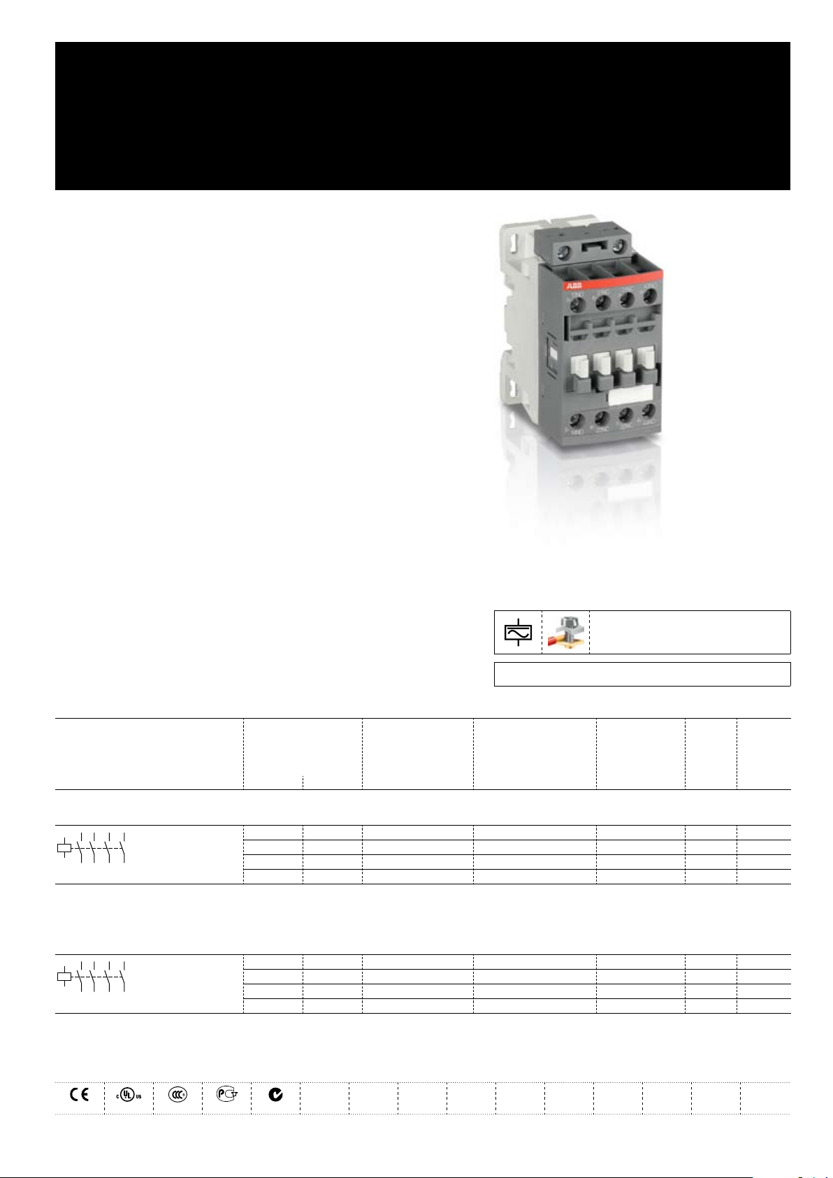
NF40E-.. / NFZ40E-.. Contactor Relays
AC / DC Operated - with Screw Terminals
NF(Z) contactor relays are used for switching auxiliary
and control circuits.
NF(Z) contactor relays include an electronic coil interface providing –
reduced pull-in and holding consumption, particularly for AC control
circuits
Only four coils are needed to cover control voltages between 24...500 V –
50/60 Hz or 20...500 V DC
NF(Z) offer extended operating limits and are suitable worldwide for
different control voltages. e.g.: the coil 100...250 V 50/60 Hz - DC is
suitable for Europe (230 V 50 Hz) and for North America (120 V 60 Hz
and 208 V 60 Hz).
NF(Z) contactors can manage large control voltage variations.
NFZ contactor relays equipped with a 24...60 V 50/60 Hz - 20...60 V DC –
coil allow direct control by 24 V DC 500 mA PLC-output
NFZ contactor relays withstand short voltage dips and voltage sags –
(SEMI F47-0706 compliance)
NF(Z) contactor relays have built-in surge protection and do not require –
additional surge suppressors.
3D CAD outline drawings available on «Control Product 3D» portal
Ordering Details
Number of contacts Control voltage Type Order code EAN Weight
1st stack Uc min. ... Uc max.
Pack
(ing)
1 piece
V 50/60 Hz V DC
kg
Contactor Relays
24...60 20...60
48...130 48...130
100...250 100...250
250...500 250...500
Note: NF40E-11 not suitable for a direct control by PLC-output. NF40E-11 available in some countries: please consult your ABB representative.
NF40E-11 1SBH 137 001 R1140
NF40E-12 1SBH 137 001 R1240
NF40E-13 1SBH 137 001 R1340
NF40E-14 1SBH 137 001 R1440
3471523100015 0.270
3471523100022 0.270
3471523100039 0.270
3471523100046 0.310
Contactor Relays - Low Consumption
- 12...20
24...60 20...60
48...130 48...130
100...250 100...250
Note: Only NFZ contactor relays with DC control voltage 12...20 V DC need to respect the connection polarities indicated close to the coil terminals: A1+ for the positive pole and A2- for the negative pole
NFZ40E-20 1SBH 136 001 R2040
NFZ40E-21 1SBH 136 001 R2140
NFZ40E-22 1SBH 136 001 R2240
NFZ40E-23 1SBH 136 001 R2340
3471523101609 0.310
3471523101616 0.310
3471523101623 0.310
3471523101630 0.310
Certifications and Approvals
ABB | Technical Datasheet 1SBC101429D0201 1
Page 2
2 Technical Datasheet 1SBC101429D0201 | ABB
Contact Utilization Characteristics according to IEC
Standards IEC 60947-1 / 60947-5-1 and EN 60947-1 / 60947-5-1
Rated operational voltage Ue max. 690 V
Conventional free-air thermal current Ith θ ≤ 40 °C 16 A
Rated frequency limits 25 ... 400 Hz
Rated operational current Ie / AC-15
acc. to IEC 60947-5-1
Making capacity AC-15 10 x Ie AC-15 acc. to IEC 60947-5-1
Breaking capacity AC-15 10 x Ie AC-15 acc. to IEC 60947-5-1
Rated operational current Ie / DC-13
acc. to IEC 60947-5-1
Short-circuit protection gG type fuse 10 A
Rated short-time withstand current I
cw
Minimum switching capacity 12 V / 3 mA
with failure rate acc. to IEC 60947-5-4
Non-overlapping time between N.O. and N.C. contacts ≥ 2 ms
Heat dissipation per pole at 6 A 0.1 W
Max. electrical switching frequency
24-127 V 50/60 Hz
220-240 V 50/60 Hz
400-440 V 50/60 Hz
500 V 50/60 Hz
690 V 50/60 Hz
24 V DC
48 V DC
72 V DC
110 V DC
125 V DC
220 V DC
250 V DC
400 V DC
500 V DC
600 V DC
for 1.0 s
for 0.1 s
AC-15
DC-13
6 A
4 A
3 A
2 A
2 A
6 A / 144 W
2.8 A / 134 W
1 A / 72 W
0.55 A / 60 W
0.55 A / 69 W
0.27 A / 60 W
0.27 A / 68 W
0.15 A / 60 W
0.13 A / 65 W
0.1 A / 60 W
100 A
140 A
-7
10
1200 cycles/h
900 cycles/h
Main Pole - Utilization Characteristics according to UL / CSA
Standards UL 508, CSA C22.2 N°14
Rated insulation voltage U
i
Max. rated voltage 600 V AC, 600 V DC
Pilot duty A600, Q600
AC thermal rated current 10 A
AC maximum volt-ampere making 7200 VA
AC maximum volt-ampere breaking 720 VA
DC thermal rated current 2.5 A
DC maximum volt-ampere making-breaking 69 VA
600 V
Page 3
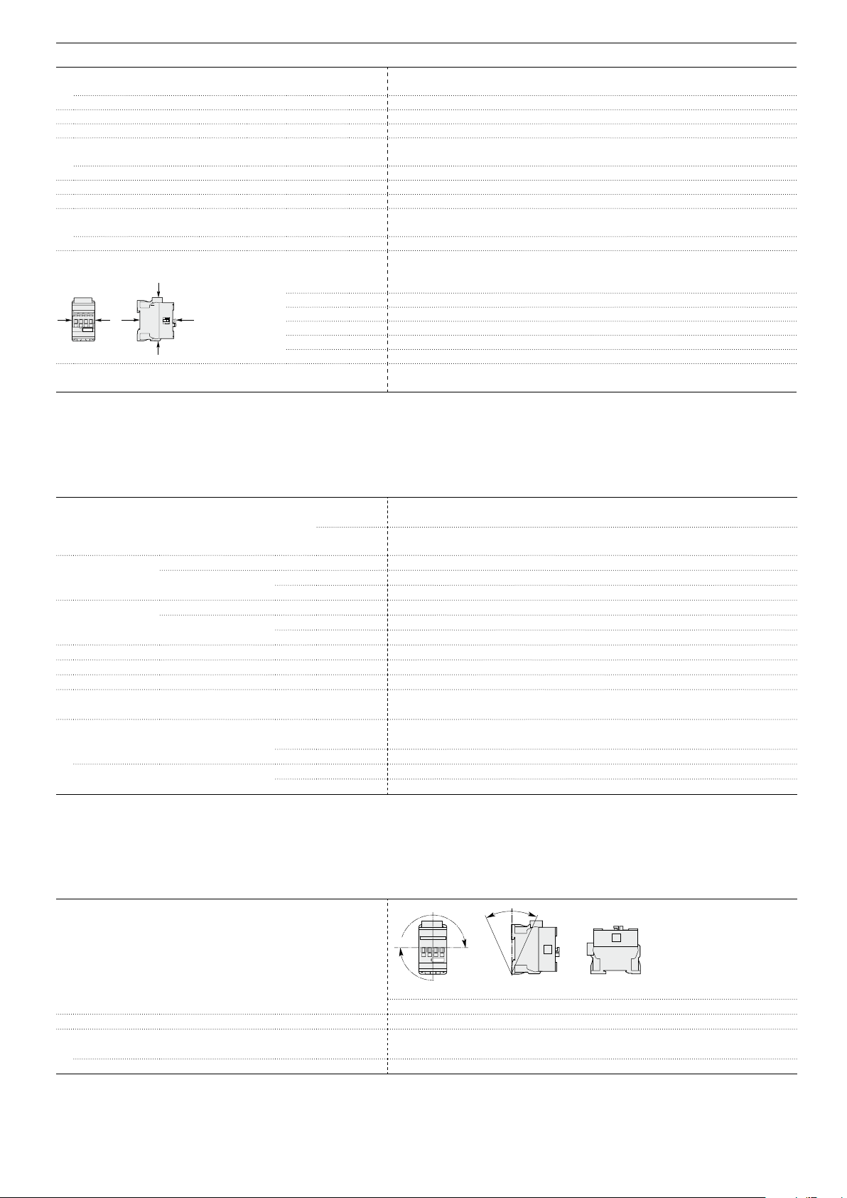
ABB | Technical Datasheet 1SBC101429D0201 3
General Technical Data
B2
A
A
B1
C2
C1
Pos. 5
Pos. 3
Pos
. 2
Pos. 1 Pos. 1 ± 30°
+30° -30°
Pos. 4
Rated insulation voltage Ui
acc. to IEC 60947-5-1
acc. to UL / CSA
Rated impulse withstand voltage Uimp 6 kV
Electromagnetic compatibility Devices complying with IEC 60947-1 / EN 60947-1 - Environment A
Ambient air temperature close to contactor
Operation in free air -40 ... +70 °C
Storage -60 ... +80 °C
Climatic withstand Category B according to IEC 60947-1 Annex Q
Operating altitude ≤ 3000 m
Mechanical durability
Number of operating cycles 20 millions operating cycles
Max. switching frequency 6000 cycles/h
Shock withstand
acc. IEC 60068-2-27 and EN 60068-2-27
Mounting position 1
Closed or open
Shock direction
position
Vibration withstand 5 ... 300 Hz
acc. to IEC 60068-2-6
690 V
600 V
1/2 sinusoidal shock for 11 ms: no change in contact position
A
30 g
B1
25 g Closed position / 5 g Open position
B2
15 g
C1
25 g
C2
25 g
4 g Closed position / 2 g Open position
Magnet System Characteristics
Coil operating limits
acc. to IEC 60947-5-1
AC control voltage Rated control circuit voltage Uc 24 ... 500 V AC
50/60 Hz Coil consumption
Average pull-in value
Average holding value
DC control voltage Rated control circuit voltage Uc 12 ... 500 V DC
Coil consumption
Average pull-in value
Average holding value
PLC-Output control (NFZ) ≥ 500 mA 24 V DC
Drop-out voltage in % of Uc min. ≤ 60 % Uc min
Voltage sag immunity according to SEMI F47-0706 (NFZ) conditions of use on request
Dips withstand (level 0% according to IEC 61000-4-11) (NFZ) 22 ms average for Uc = 24 ... 250 V 50/60Hz
-20 °C ≤ θ ≤ +60 °C
Operating time
between coil energization and:
between coil de-energization and:
N.O. contact closing
N.C. contact opening
N.O. contact opening
N.C. contact closing
AC supply
DC supply
at θ ≤ 60°C 0.85 x Uc min ... 1.1 x Uc max
at θ ≤ 70°C 0.85 x Uc min ... Uc max
at θ ≤ 60°C 0.85 x Uc min ... 1.1 x Uc max
at θ ≤ 70°C (NF) 0.85 x Uc min ... Uc max - (NFZ) 0.85 x Uc min ... 1.1 x Uc max
(NF) 50 VA - (NFZ) 16 VA
(NF) 2.2 VA / 2 W - (NFZ) 1.7 VA / 1.5 W
(NF) 50 W - (NFZ) 12 ... 16 W
(NF) 2 W - (NFZ) 1.7 W
40 ... 95 ms
38 ... 90 ms
11 ... 95 ms
13 ... 98 ms
Mounting Characteristics
Mounting positions
Max. add-on N.C. auxiliary contacts: see accessory fitting details for a NF contactor relay
Mounting distances The contactor relays can be assembled side by side.
Fixing
on rail according to IEC 60715, EN 60715 35 x 7.5 mm or 35 x 15 mm
by screws (not supplied) 2 x M4 screws placed diagonally
Page 4

4 Technical Datasheet 1SBC101429D0201 | ABB
Connecting Characteristics
L
6
Main terminals
Connecting capacity (min. ... max.)
Pole and coil terminals
Rigid
Flexible with non insulated ferrule
Flexible with insulated ferrule
Bars or lugs
Screw terminals with cable clamp
1 x
1 ... 2.5 mm²
2 x
1 ... 2.5 mm²
1 x
0.75 ... 2.5 mm²
2 x
0.75 ... 2.5 mm²
1 x
0.75 ... 2.5 mm²
2 x
0.75 ... 1.5 mm²
L <
8 mm
Capacity according to UL/CSA
1 or 2 x
AWG 18 ... 14
Stripping length 10 mm
Degree of protection
acc. to IEC 60947-1 / EN 60947-1 and IEC 60529 / EN 60529
All terminals IP20
Screw terminals (delivered in open position, screws of unused terminals must be tightened)
All terminals M3.5
Screwdriver type Flat Ø 5.5 / Pozidriv 2
Tightening torque
Pole terminals 1.2 Nm / 11 lb.in
Coil terminals 1.2 Nm / 11 lb.in
Page 5

ABB | Technical Datasheet 1SBC101429D0201 5
Accessory Fitting Details for a NF Contactor Relay
Front-mounted accessories Side-mounted accessories
Auxiliary contact blocks Auxiliary contact blocks
1-pole CA4
Left side Right side
1-pole CC4 4-pole CA4 2-pole CAL4-11
Max. add-on N.C. auxiliary contacts: 4 N.C. max. on positions 1, 2, 3, 4 and 3 N.C. max. on positions 1 ±30°, 5
4 max. or 1 + 1 –
2 max. – + 1 + 1
NF contactor relay
4-pole CA4
1-pole CA4, CC4
2-pole CAL4-11
Many configurations of accessories are possible depending on whether these are front-mounted or side-mounted.
Overview of main accessories (other accessories available)
Page 6

6 Technical Datasheet 1SBC101429D0201 | ABB
Main Accessories
Ordering Details
Description Auxiliary
Additional auxiliary
contact blocks
Front-mounted instantaneous
auxiliary contact blocks
contacts
0 1 - - CA4-01 1SBN 010 110 R1001 3471523130029 1 0.014
1 0 - - CA4-10 1SBN 010 110 R1010 3471523130005 1 0.014
0 1 - - CA4-01-T 1SBN 010 110 T1001 3471523130395 10 0.014
1 0 - - CA4-10-T 1SBN 010 110 T1010 3471523130371 10 0.014
Type Order code EAN Pack
piece
(ing)
Weight
kg
(1 pce)
Front-mounted auxiliary contact
blocks with N.O. leading contact and
N.C. lagging contact
Side-mounted instantaneous auxiliary
contact blocks
Front-mounted instantaneous
auxiliary contact blocks
Additional coil terminal
block
Protective covers Protective covers BX4 1SBN 110 108 T1000 3471523130708 10 0.006
Additional coil terminal block LDC4 1SBN 070 156 T1000 3471523130678 10 0.010
- - 0 1 CC4-01 1SBN 010 111 R1001 3471523130432 1 0.014
- - 1 0 CC4-10 1SBN 010 111 R1010 3471523130425 1 0.014
1 1 - - CAL4-11 1SBN 010 120 R1011 3471523130043 1 0.040
1 1 - - CAL4-11-T 1SBN 010 120 T1011 3471523130418 10 0.040
0 4 - - CA4-04N 1SBN 010 140 R1204 3471523130289 1 0.055
1 3 - - CA4-13N 1SBN 010 140 R1213 3471523130272 1 0.055
2 2 - - CA4-22N 1SBN 010 140 R1222 3471523130241 1 0.055
3 1 - - CA4-31N 1SBN 010 140 R1231 3471523130258 1 0.055
4 0 - - CA4-40N 1SBN 010 140 R1240 3471523130265 1 0.055
BX4-CA 1SBN 110 109 W1000 3471523130715 50 0.001
Function markers Function markers BA4 1SNA 235 156 R2700 3472592351568 16 0.011
HTP500-BA4 1SNA 235 712 R2400 3472592357126 1 0.220
SPRC 1 1SNA 360 010 R1500 3472593600108 1 0.290
Page 7

45 1.77"
80 3.15"
6 0.24"
77 3.03"
71 2.80"
5.5 0.22"
35 mm
EN/IEC 60715
10 0.39"
5.5 0.22"
35 1.38"
70 2.76"
60 2.36"
5 0.20"
5 0.20"
ø 4.2 0.17"
2 x
M4 8-32 UNC
35 1.38"
70 2.76"
60 2.36"
5 0.20"
5 0.20"
ø 4.2 0.17"
2 x
M4 8-32 UNC
45 1.77"
80 3.15"
6 0.24"
43 1.69"
110.5 4.35"
71 2.80"
5.5 0.22"
35 mm
EN/IEC 60715
5.5 0.22"
10 0.39"
45 1.77"12 0.47"
80 3.15"
6 0.24"
77 3.03"
71 2.80"
5.5 0.22"
35 mm
EN/IEC 60715
10 0.39"
5.5 0.22"
45 1.77"
80 3.15"
6 0.24"
110.5 4.35"
71 2.80"
5.5 0.22"
35 mm
EN/IEC 60715
10 0.39"
5.5 0.22"
43 1.69"
ABB | Technical Datasheet 1SBC101429D0201 7
Terminal Marking and Positioning
43
NO
44
33
NO
34
23
NO
24
13
NO
NONONONO
14
A1 A2
A1 A2
43
NO
NO
44
33
NO
NO
34
23
NO
NO
24
13
NO
NO
14
A1
A2
Standard devices without addition of auxiliary contacts
NF40E-.. / NFZ40E-..
NF40E-.. / NFZ40E-..
Dimensions mm, inches
NF40E NF40E
NF40E NF40E
+ CA4, CC4 1-pole auxiliary contact block + CAL4-11 2-pole auxiliary contact block
NF40E
+ CA4 4-pole auxiliary contact block
Note: contactor lateral distance to grounded component 2 mm 0.08" min.
 Loading...