

Application guide—Miniature circuit breaker
Introduction
The circuit breaker plays an important role in providing overcurrent protection and a disconnect means in electrical networks.
Recent advancements in circuit breaker technology has increased
breaker performance and protection.
Overload
An overload is a slow and small overcurrent situation that causes
the ampacity and temperature of the circuit to gradually increase
over time. This type of event is characterized by a slight increase
in the load (ampacity) on the circuit and is interrupted by the
thermal trip unit of the breaker.
Thermal Example
10 A
15 A
Breaker
Light
Breaker definition
A breaker is a device designed to isolate a circuit during an
overcurrent event without the use of a fusible element. A
breaker is a resettable protective device that protects against
two types of overcurrent situations: overload and short circuit.
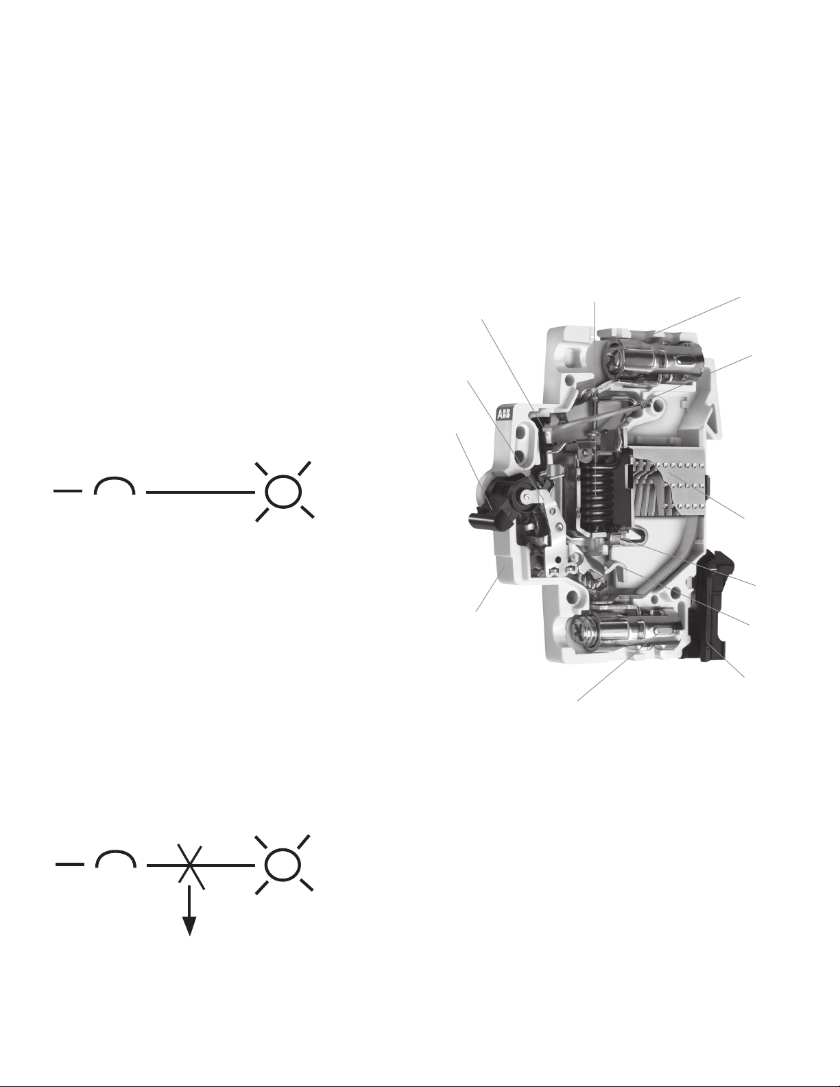
ABB current limiting breaker
Electromagnetic protection
Tripping lever
Operating
mechanism
Operator
Upper terminal
Thermal
protection
(bimetal)
Arc chamber
The light draws more than 10 amps for
an extended period of time creating a
thermal overload.
Short circuit
A short circuit is a rapid and intense overcurrent situation that
causes the ampacity of the circuit to increase. This type of event is
characterized by a dramatic increase in the load (ampacity) on the
circuit and is interrupted by the magnetic trip unit of the breaker.
Magnetic Example
10 A
10 A
Breaker
Light
The wire connected between the light and
breaker is cut and shorted to ground
creating a short circuit.
Space for
identification marker
Fixed
contact
Moving
contact
DIN rail holder
Lower terminal
42 Miniature Circuit Breakers | US Catalog
Trip bar
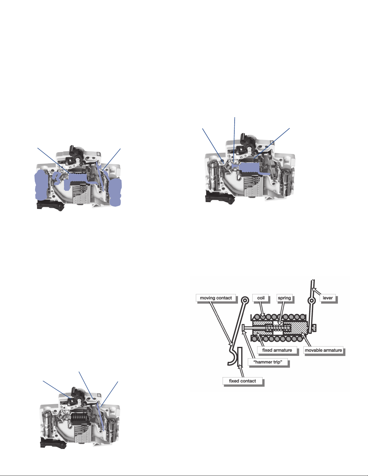
Current Flow During Operation
All highlighted components are energized during operation
Current flow during operation
Circuit breaker construction
Thermal/Magnetic trip units definition
ABB Current Limiting Breakers use an electromechanical
(Thermal/Magnetic) trip unit to open the breaker contacts during
an overcurrent event. The thermal trip unit is temperature sensitive
and the magnetic trip unit is current sensitive. Both units act
independently and mechanically with the breaker’s trip
mechanism to open the breaker’s contacts.
Current fl ow during operation
Magnetic Trip Unit
Magnetic trip unit
All highlighted components are energized during operation
Thermal Trip Unit
Thermal trip unit
Thermal trip unit
.
Overload protection
The thermal trip unit protects against a continuous overload.
The thermal unit is comprised of a bimetal element located
behind the circuit breaker trip bar and is part of the breaker’s
current carrying path. When there is an overload, the increased
current flow heats the bimetal causing it to bend. As the bimetal
bends, it pulls the trip bar that opens the breaker’s contacts.
Magnetic trip units (short circuit protection)
The magnetic trip unit protects against a short circuit. The
magnetic trip unit is comprised of an electromagnet and an
armature.
Armature and plunger
Armature and plunger
Movable contact
Movable contact
Magnetic trip unit
Magnet trip unit
Components of a magnetic trip unit
When there is a short circuit, a high magnitude of current
passes through the coils creating a magnetic field that attracts
the movable armature towards the fixed armature. The hammer
trip is pushed against the movable contact and the contacts are
opened. The opening of the breaker’s contacts during a short
circuit is complete in .5 milli-seconds.
The time required for the bimetal to bend and trip the breaker
varies inversely with the current. Because of this, the tripping
time becomes quicker as current increases in magnitude.
Overload protection is applicable to any installation, conductor,
or component that can be subjected to low-magnitude but
long-time overcurrents. Low-magnitude, long-time overcurrents
can be dangerous because they reduce the life of the electrical
installation, conductor, and components. If left unchecked, fire
could result.
Trip bar
Operating mechanism
Operating mechanism
Thermal trip unit
Thermal trip unit
US Catalog | Miniature Circuit Breakers 43
Circuit breaker construction
Arc runners/arc chutes
The arc runner guides the electric arc away from the open contacts
into the arc chute where it is extinguished.
During an overload or short circuit event, the contacts of the
breaker separate, and an electrical arc is formed between the
contacts through air. The arc is moved into the arc chute by
“running” the arc down the interior of the breaker along the arc
runner. When the arc reaches the arc chute, it is broken into
small segmented arcs. The segmented arcs split the overall
energy level into segments less than 25 V. Each 25 V segment
does not have a high enough energy level to maintain an arc
and all energy is naturally dissipated.
Arc runner
Arc runner Arc chute
Arc chute
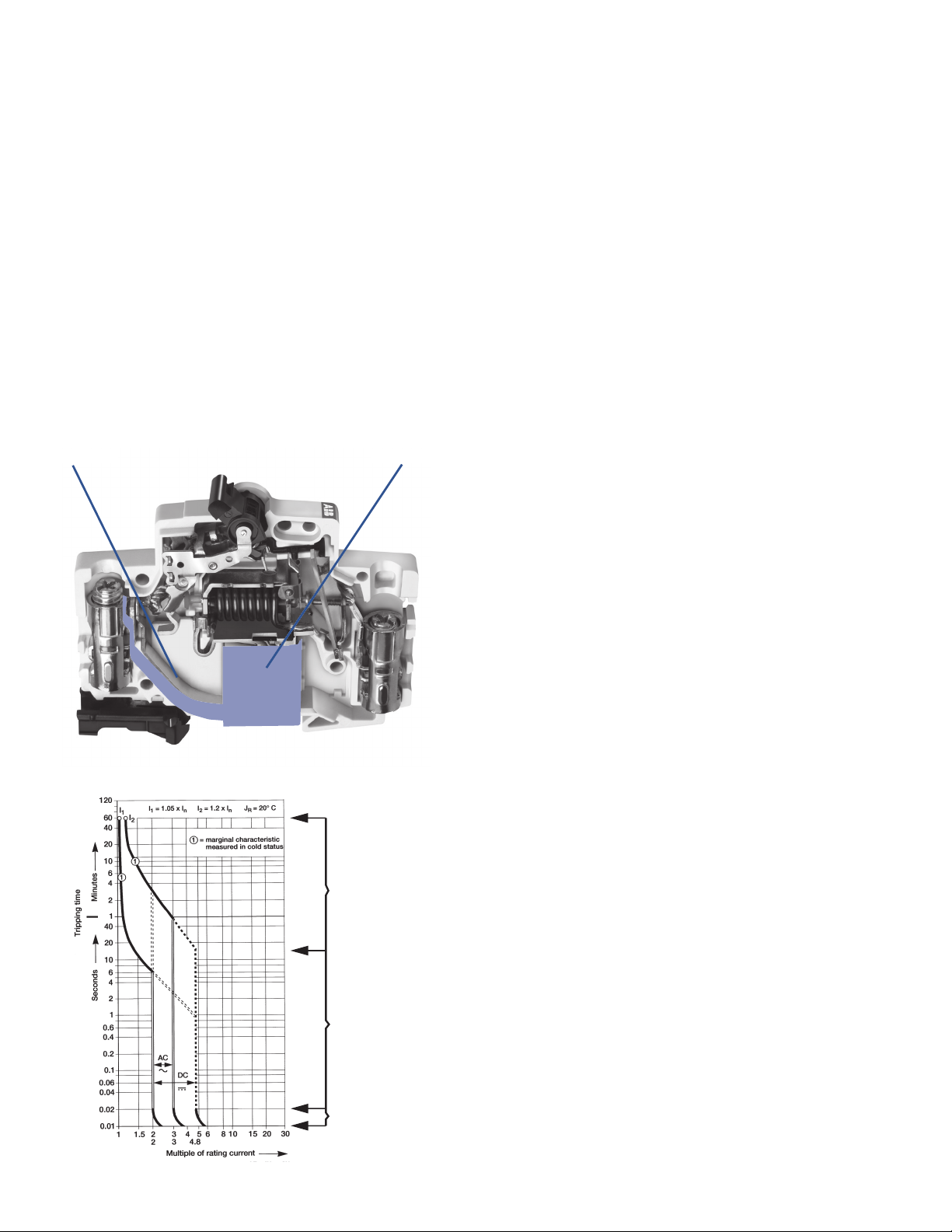
Breaker curves
Thermal trip unit (region one)
The first sloping region of the breaker curve is a graphical
representation of the tripping characteristics of the thermal trip
unit. This portion of the curve is sloped due to the nature of the
thermal trip unit. The trip unit bends to trip the breaker’s trip bar
in conjunction with a rise in amperage (temperature) over time.
As the current on the circuit increases, the temperature rises,
the faster the thermal element will trip.
Example using the curve below: If you had a 10 A breaker and
the circuit was producing 30 amps of current, the breaker would
trip between two seconds and one minute. In this example, you
would find the circuit current on the bottom of the graph
(multiples of rated current). The first line is 10 amps (10 amp
breaker x a multiple of one), the second line is 20 amps (10 amp
breaker x multiple of two), and the third line is 30 amps (10 amp
breaker x multiple of three). Next, you would trace the vertical 30
A line up until it intersects the red portion of the breaker thermal
curve. If you follow the horizontal lines on both sides of the red
curve to the left, you will see that the breaker can trip as fast as
two seconds and no slower than one minute.
Magnetic trip unit (region two)
This region of the breaker curve is the instantaneous trip unit.
ABB’s miniature circuit breaker’s instantaneous trip unit interrupts
a short circuit in 2.3 to 2.5 milliseconds. Because of this, the
curve has no slope and is graphically represented as a vertical
straight line.
44 Miniature Circuit Breakers | US Catalog
Thermal Trip Unit
(Region One)
Magnetic Trip Unit
(Region Two)
Moving Contacts
(Region Three)
See curve example. If you had a 10 amp breaker, the magnetic
trip element would interrupt a short circuit between 10 and 30
amps (10 amp breaker x multiple of two and three) in 2.3 to 2.5
milliseconds.
Breaker contacts (region three)
This region of the curve is the time required for the contacts of
the breaker to begin to separate. The contacts will open in less
than .5 milliseconds and is graphically represented by the bottom
vertical portion of the curve.

Circuit breaker current limitation
Current limiting definitions
All ABB miniature circuit breakers are UL tested and certified as
current limiting protective devices. Current limiting circuit breakers
provide a higher level of circuit protection than typical zero point
external breakers.
UL AC 60 Hz cycle
UL defines an AC cycle as the potential energy of the wave form
traveling from zero-to-positive amplitude, positive-to-zero
amplitude, zero-to-negative amplitude, negative-to-zero
amplitude 60 times in one second. One cycle is completed
every 16.6 milliseconds.
UL breaker current limiting
UL defines breaker current limitation as a breaker that interrupts
and isolates a fault in less than ½ of an AC cycle. ½ a cycle is
completed in 8.3 milliseconds.
NEC240.2 current limiting
A device that, when interrupting current in its current-limiting
range, reduces the current flowing in the faulted circuit to a
magnitude substantially less than that obtainable in the same
circuit if the device were replaced with a solid conductor having
comparable impedance.
IEC 60947-2 current limiting circuit breaker
A circuit breaker with sufficiently short trip time to prevent the
short-circuit current from reaching the peak value which would
otherwise be reached.
ABB current limiting breakers
ABB current limiting breakers can interrupt and isolate a fault in
of an AC cycle. The breaker fault interruption is completed in
2.3 to 2.5 milliseconds.
Zero point extinguishing breakers
A typical zero point extinguishing breaker interrupts a fault and
does not isolate the energy. The breaker allows an arc to be
present between the open contacts until the AC wave form
crosses zero. When the wave form crosses zero, the potential
energy is zero and the arc (fault) naturally extinguishes. The arc
could be present for up to 8.3 milliseconds.
Current limiting breakers and electrical networks
Current Limitation
When a short-circuit condition occurs, the “ideal” current limiting
circuit breaker opens before the current waveform can reach its
full potential magnitude which occurs at ¼ cycle (4.17ms). ABB’s
current limiting breakers can interrupt a fault in about ½ cycle or
2.3 ms to 2.5 ms. ABB’s current limiting breakers interrupt a short
circuit in less than cycle and limit the amount of current that
can reach a circuit. Limiting the available current on the circuit
provides additional protection against network, breaker, or bus
damage and prevents the tripping of upstream breakers (selective
coordination).
2
t
I
The true destructive nature of a short circuit is measured by the
time it is available combined with the peak value of the short
circuit. The IsqT (Amps Squared over Time) value represents the
amount of energy available on a network during a short circuit
and is represented by the shaded area on the graph below.
During a short circuit, both magnetic forces and thermal energy
combine to damage devices on the electrical network. The level
of thermal energy and magnetic forces are directly proportional
to the square of the current. The magnetic forces vary as a
square of the peak current available and the thermal energy varies
as a square of the RMS (root mean square) current available.
ABB’s current limiting breakers will limit the let-through energy
to a fraction (⁄) of the value that is available from the
network. By comparison, a zero crossing breaker would let
through approximately 100 times as much destructive energy
as the current limiting circuit breaker [ (100,000A / 10,000A)
squared – 100X]. ABB’s current limiting breakers limit the short
circuit current to a relatively small magnitude in an extremely
short time, which dramatically limits a short circuit’s destructive
energy.
US Catalog | Miniature Circuit Breakers 45

Circuit breaker current limitation
Current limiting and zero crossing breakers
During the initial stages of a short circuit, a breaker’s contacts
open to interrupt the circuit. After the contacts open, an arc
forms in the air between the contacts on both the current limiting
and zero crossing breaker contacts. What distinguishes a current
limiting breaker from a zero, crossing breaker is what each
breaker does after an arc is formed between the open contacts.
A current limiting breaker “runs” the arc down the breaker arc
runner into an arc chute that extinguishes the arc.
A zero crossing breaker does not attempt to extinguish the arc.
The breaker is designed to withstand the energy of the arc long
enough for the waveform to cross zero. When the wave form
crosses zero the potential energy is zero and the arc naturally
extinguishes itself.
ABB’s current limiting breakers interrupt the arc energy in 2.3
ms to 2.5 ms ( cycle) and a zero crossing breaker allows the
arc to be present for up to 8.3 ms (½ cycle). A zero crossing
breaker will let through 100 times as much energy as an ABB
current limiting breaker.
Current limiting example
The lab test report below details a 20 A S200 series current
limiting breaker interrupting a 28 kA fault in 1.7 milliseconds.
The total “I Square T” value is 32.0 kA.
Zero crossing example
The test report below details a 20 A zero point extinguishing
breaker interrupting a 9 kA fault in 9 milliseconds. The total
“I Square T” value is 104.0 kA.
U-BCP L2
100 /div
-100
-200
-300
-400
500
400
300
200
100
10
V
kA
8
6
4
2
I-L2
2 k/div
-2
-4
-6
Legend
Voltage
-8
Amps
U-L2
100 /div
500
10
V
kA
400
8
300
6
200
4
100
2
I-L2
2 k/div
-100
-2
-200
-4
-300
-400
-500
-10
Legend
-6
Voltage
Amps
-8
0 6.9990.9999 1.9997 2.9996 3.9994 4.9993 5.9991
Time A Time B
-500
kSample499.93 Sample/div
-10
0 6.9990.9999 1.9997 2.9996 3.9994 4.9993 5.9991
Time A Time B
kSample499.93 Sample/div
46 Miniature Circuit Breakers | US Catalog

Selective coordination and series ratings
Definition of selective coordination
Coordination between the operating characteristics of two or more
overcurrent protection devices, so that when an over-current within
established limits occurs, the device designated to operate within
those limits trips whereas the other devices does not trip.
Main
breaker
CB1 CB2 CB3 CB4
Short circuit
Example of breaker coordination
When an over-current event occurs at the branch breaker level
(CB1), and the event is within the operating characteristics of
the breaker, then the branch breaker should interrupt the circuit
(open) and the main breaker should remain closed and energized.
The chart below gives a graphical representation of a down
stream branch breaker (B curve) and a main breaker (A curve)
with coordination. The separation between the curves allows the
branch breaker to react to the fault and the main breaker remains
closed and energized.
Example of no breaker coordination
Selective breaker coordination is not achieved when there is an
overload event at the branch breaker level (MCB1) and both the
branch breaker and main breaker interrupt the circuit (open).
When there is no breaker coordination, several circuits lose
power that should remain operational during and after the overload event. The chart below gives a graphical representation
of a down stream branch breaker (B curve) and a main breaker
(A curve) without coordination. There is no separation between
the curves. The branch breaker will react to a fault and the main
breaker will open and de-energize all circuits down stream.
Problems in coordination occur when the branch breaker allows
the “I Square T” value of the short circuit to rise to a level that
is in the operating range of the upstream main breaker. Proper
breaker coordination is easier to achieve with the use of current
limiting breakers at the branch level.
Selective coordination and current limiting breakers
Recent improvements in ABB circuit breaker technology has
pushed the performance of breakers to the same level as fuses.
The reaction time and tripping characteristics of current limiting
breakers are now on par with fuses. This allows ABB to provide
a high level of coordination between branch breakers and the
main. A current limiting branch breaker will limit the “I Square T”
value well below the level of the operating range of the upstream main breaker. ABB’s current limiting branch breakers can
coordinate between the main breaker up to 35 kA.
Selective coordination and zero crossing breakers
Zero crossing breakers do not limit the “I Square T” value. They
wait for the wave form to cross zero and allow a high level of
let-through energy to pass through the system. The “I Square
T” value of a zero crossing breaker is high enough that the main
breaker will likely trip during a short circuit. With zero crossing
breakers it is extremely difficult to coordinate between branch
and main breakers. A typical zero crossing breaker’s coordination
level is below 10 kA. There are a few manufacturers that have
achieved coordination between a branch zero crossing breaker
and the main by slowing the performance (protection) of the
main breaker.
US Catalog | Miniature Circuit Breakers 47

Selective coordination and series ratings
Selective coordination
Selective coordination is achieved when there is a short circuit
on a branch circuit breaker, the branch breaker opens and
isolates the fault, and the main breaker remains closed. The rating
is usually a value above the “stand alone” interrupting rating
of the branch breaker and the “stand alone” rating of the main
breaker.
Example:
65 kA rated main breaker
10 kA rated branch breaker
Coordination between the two breakers up to 35 kA
There can be a short circuit on the branch breaker up to 35 kA
where the branch will open (CB1) and the main breaker will
remain closed. Although the branch has a 10 kA “stand alone”
rating, both the breakers work together to limit the available
short circuit to allow the branch (CB1) to isolate the fault.
Main
breaker
65 kA
CB1
10 kA
CB2
10 kA
CB3
10 kA
CB4
10 kA
Series ratings
Series ratings are different from coordination ratings. Unlike
coordination ratings where the branch opens and the main
remains closed, a series rated combination is one where both the
branch and main breakers open and work together to isolate the
fault.
The series rating combination of two breakers is equal to the
“stand alone” interrupting value of the main breaker. This is a
result of the main breaker let-through value being lower than the
“stand alone” interrupting value of the branch breaker. During a
short circuit the main breaker will limit the energy to a level that
is below the “stand alone” value of the branch breaker.
Example:
65 kA rated main breaker
10 kA rated branch breaker
Series combination rating between the two breakers up to 65 kA
There can be a short circuit on the branch breaker up to 65
kA where the branch will open and the main breaker will open.
Although the branch breaker (CB1) has a 10 kA “stand alone”
rating the main breaker has a let-through value below 10 kA.
If there is a fault up to 65 kA on the network, the main breaker
will limit the energy to a value less than the rating of the branch
breaker (CB1). Both breakers will trip (no coordination), but the
network can safely withstand a fault of 65 kA.
35 kA or 65 kA short circuit
48 Miniature Circuit Breakers | US Catalog

Miniature circuit breaker cutaway
Tripping lever
Operating mechanism
Operator
Electromagnetic protection
Upper terminal
Thermal protection (bimetal)
Arc chamber
Space for identification marker
Fixed contact
Moving contact
DIN rail holder
Lower terminal
US Catalog | Miniature Circuit Breakers 49
 Loading...