

Page 1
User Guide
IM/C505_6
Control
1
/2 DIN Advanced Process Controller
C505
IT
Page 2
ABB
The Company
We are an established world force in the design and manufacture of
instrumentation for industrial process control, flow measurement, gas and
liquid analysis and environmental applications.
As a part of ABB, a world leader in process automation technology, we
offer customers application expertise, service and support worldwide.
We are committed to teamwork, high quality manufacturing, advanced
technology and unrivalled service and support.
The quality, accuracy and performance of the Company’s products result
from over 100 years experience, combined with a continuous program of
innovative design and development to incorporate the latest technology.
The UKAS Calibration Laboratory No. 0255 is just one of the ten flow
calibration plants operated by the Company, and is indicative of our
dedication to quality and accuracy.
BS EN ISO 9001:2000
R
E
G
R
I
S
E
T
Cert. No. Q5907
EN 29001 (ISO 9001)
Lenno, Italy – Cert. No. 9/90A
Use of Instructions
✶
Warning.
An instruction that draws attention to the risk of
injury or death.
Caution.
An instruction that draws attention to the risk of
damage to the product, process or surroundings.
Although
Warning hazards are related to personal injury, and Caution hazards are associated with equipment or
property damage, it must be understood that operation of damaged equipment could, under certain operational
conditions, result in degraded process system performance leading to personal injury or death. Therefore, comply
fully with all
Information in this manual is intended only to assist our customers in the efficient operation of our equipment. Use
of this manual for any other purpose is specifically prohibited and its contents are not to be reproduced in full or part
without prior approval of the Technical Communications Department.
Warning and Caution notices.
Note.
Clarification of an instruction or additional
information.
Information.
Further reference for more detailed information
or technical details.
D
E
Health and Safety
To ensure that our products are safe and without risk to health, the following points must be noted:
1. The relevant sections of these instructions must be read carefully before proceeding.
2. Warning labels on containers and packages must be observed.
3. Installation, operation, maintenance and servicing must only be carried out by suitably trained personnel
and in accordance with the information given.
4. Normal safety precautions must be taken to avoid the possibility of an accident occurring when operating
in conditions of high pressure and/or temperature.
5. Chemicals must be stored away from heat, protected from temperature extremes and powders kept dry.
Normal safe handling procedures must be used.
6. When disposing of chemicals ensure that no two chemicals are mixed.
Safety advice concerning the use of the equipment described in this manual or any relevant hazard data
sheets (where applicable) may be obtained from the Company address on the back cover, together with
servicing and spares information.
Page 3
GETTING STARTED
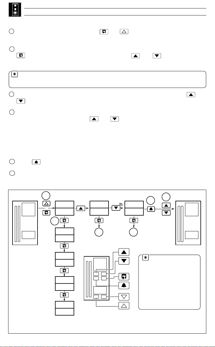
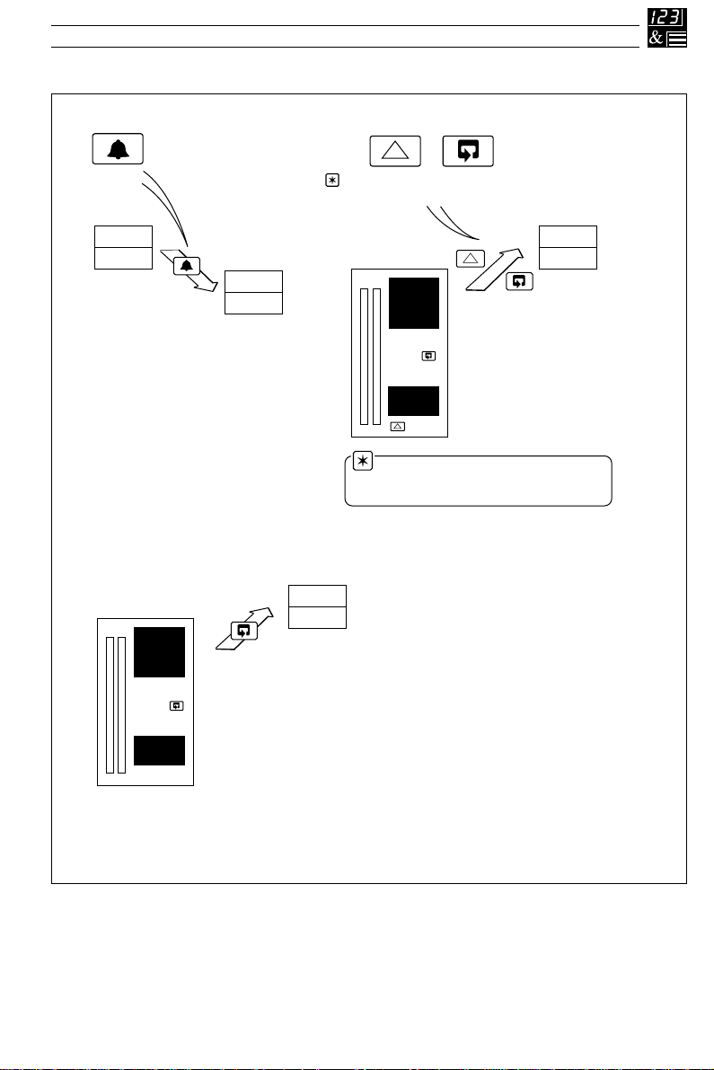
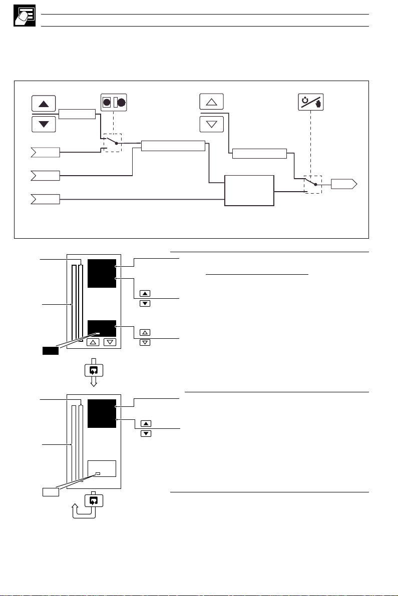
Step 3 – Setting the Parameters (Fig. GS.1)
A
Pow er-up the instrument. Press the and keys simultaneously and hold f or
3 seconds to advance directly to Level 6 – Basic Configuration.
B
Set the appropriate application template, output type and control action. Use the
key to advance between frames and upper and keys to adjust the
default values – see Section 4.2 for further information.
Note. When the output type has been selected, the availab le inputs and outputs
default to the settings shown in Table B on the rear fold-out.
C
If you are not using 4 to 20mA inputs, then select Level 7 using the upper and
keys and set up Analog Inputs I/P1 to I/P3 to suit your process – see Section 4.3.
D
Controller templates only:
Select Level 2 using the upper and keys and set the tune parameters:
• Analog or Motorized Valve Control – set the Proportional, Integral and
Derivative terms.
• Time Proportioning Control – set the Cycle Time, Hysteresis and P, I & D Terms
• Heat/Cool Outputs – set the points at which the Output 1 and Output 2
become active.
E
Press to return to the Operating displays.
F
Adjust the set point to the required value.
Your COMMANDER 500 is now in operation
50.1
50.5
50
A
+
LEV.6
APPL
LEV.7
INPt
LEV2
tUNE
F
E
50.1
50.5
B
t.APP
C D
50
01.SL
O.tYP
ANLG
C.ACt
rEV
FrEJ
50.1
50.5
50
Note. With the
above configuration,
no alarms or limits
have been set and
advanced functionality
(gain scheduling, set
point sources etc.) has
not been enabled.
50
Fig. GS.1 Setting the Parameters
Page 4

GETTING STARTED
The COMMANDER 500 can be configured and made ready for operation in three easy
steps. This 'Getting Started' guide provides an overview of these steps and, where
necessary, refers to the relevant section of the manual.
Step 1 – Decide on the Application Template and the
Output Configuration required
Step 2 – Connect the process inputs and outputs
Step 3 – Power up the instrument, set the template number and the output
configuration details
Your COMMANDER 500 is now ready for operation
Step 1 – Application Template and Output Configuration
• Choose the Template which best suits your application from the list in Table A,
located on the rear fold-out.
• Choose the Control Output Type required from the list of options in Table B on the
rear foldout.
Step 2 – Electrical Connections
Using the labels on the back of the instrument as a guide, connect the process inputs,
outputs and power supplies. Refer to Section 5.2 of this man ual (Electrical Installation)
for more information.
Continued…
Page 5
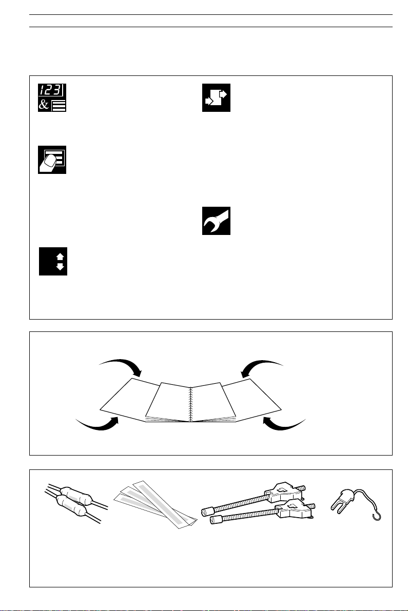
OVERVIEW
This manual is divided into 5 sections which contain all the information needed to install, configure,
commission and operate the COMMANDER 505 Advanced Process Controller. Each section is
identified clearly by a symbol as shown in Fig. 1.
8
Displays and Controls
• Displays and Function Keys
• LED Indication
• Error Messages
Operator Mode (Level 1)
• Single Loop Controller
• Motorized Valve Controller
• Auto/Manual &
Backup Stations
• Feedforward Controllers
• Cascade Controllers
• Ratio Station/Controller
Set Up Mode (Levels 2 to 5)
• Level 2 – Tuning
• Level 3 – Set Points
• Level 4 – Alarm Trip Points
• Level 5 – Valve Setup
Fig. 1 Overview of Contents
Getting
Started
Configuration Mode (Levels 6 to E)
• Level 6 – Basic Configuration
• Level 7 – Input Configuration
• Level 8 – Alarm Configuration
• Level 9 – Set Point Configuration
• Level A – Control Configuration
• Level B – Operator Configuration
• Level C – Output Configuration
• Level D – Serial Communications
• Level E – System Calibration
Installation
• Siting
• Mounting
• Electrical Connections
Table A – Template Applications
B – Output Sources
Getting
Started
Shunt Resistors
2 x 100Ω
(+1 optional)
Process Labels
x3
Fig. 3 Accessories
Fig. 2 Foldouts
Panel Clamps
x2
Table C – Digital Sources
D – Analog Sources
CJ Sensor
x1
(+1 optional)
1
Page 6

CONTENTS
Section Page
OVERVIEW....................................................1
1 DISPLAYS AND FUNCTION KEYS ........3
1.1 Introduction .......................................3
1.2 Use of Function Keys .......................4
1.3 Secret-til-Lit Indicators......................8
1.4 Character Set ....................................8
1.5 Error Messages ................................9
1.6 Processor Watchdog ......................10
1.7 Loop Break Monitor ........................10
1.8 Glossary of Abbreviations...............10
2 OPERATOR LEVEL............................... 11
2.1 Introduction ..................................... 11
2.2 Single Loop Controller
(Templates 1 and 2)........................1 2
2.3 Auto/Manual Station
(Templates 3 and 4)........................1 4
2.4 Analog Backup
(Templates 5 and 6)........................1 6
2.5 Indicator/Manual Loader Station
(Templates 7 and 8)........................1 8
2.6 Single Loop with Feedforward
(Templates 9 and 10)......................19
2.7 Cascade Control
(Templates 11 and 12) .................... 21
2.8 Cascade with Feedforward
(Template 13) ..................................24
2.9 Ratio Controller
(Templates 14 and 15)....................26
2.10Ratio Station
(Templates 16 and 17)....................27
2.11 Heat/Cool Output Types .................28
2.12Motorized Valve Output Types .......29
2.13Auto-tune ........................................30
2.14Control Efficiency Monitor ..............33
3 SET UP MODE .......................................36
3.1 Introduction .....................................36
3.2 Level 2 – Tune ................................ 37
3.3 Level 3 – Set Points........................41
3.4 Level 4 – Alarm Trip Points.............43
3.5 Level 5 – Valve Setup.....................44
4 CONFIGURATION MODE ..................... 47
4.1 Introduction...................................... 47
4.2 Level 6 – Basic Configuration ........48
4.3 Level 7 – Analog Inputs ..................52
4.4 Level 8 – Alarms .............................56
4.5 Level 9 – Set Point Configuration...60
4.6 Level A – Control Configuration......63
4.7 Level B – Operator Configuration...68
4.8 Level C – Output Assignment.........70
4.9 Level D – Serial Communications ..76
4.10Level E – Calibration ......................77
2
Section Page
5 I NSTALLATION......................................80
5.1 Mechanical Installation ...................80
5.2 Electrical Installation .......................85
5.3 Relays ............................................. 87
5.4 Digital Output ..................................87
5.5 Control or Retransmission
Analog Output .................................87
5.6 Motorized Valve Connections .........88
5.7 Input Connections ...........................89
5.8 Output Connections ........................89
5.9 Power Supply Connections.............89
SPECIFICATION .........................................90
APPENDIX A – CONTROL TEMPLATES ..94
A1 Single Loop Controller
(Templates 1 and 2) ........................94
A2 Auto/Manual Station and
Analog backup Station.................... 95
A3 Indicator/Manual Loader Station
(Templates 7 and 8) ........................98
A4 Single Loop Controller with
Feedforward (Templates 9 and 10). 99
A5 Cascade Controllers
(Templates 11 and 12)..................100
A6 Cascade Controller with
Feedforward (Template 13)...........101
A7 Ratio Controller
(Templates 14 and 15)..................102
A8 Ratio Station
(Templates 16 and 17)..................103
APPENDIX B – COMMANDER
CONFIGURATION EDITOR......................104
B1 Introduction ...................................104
B2 Analog Input Customization ......... 104
B3 Programmable Maths Blocks........104
B4 Logic Equations ............................104
B5 Process Alarm Customization ......104
B6 Real Time Alarms .........................104
B7 Delay Timers .................................105
B8 Custom Linearizers.......................105
B9 Template Customization ...............105
B10 Connecting the COMMANDER
PC Configurator ............................105
FRAMES INDEX .......................................106
INDEX ......................................................109
Page 7
1 DISPLAYS AND FUNCTION KEYS
1.1 Introduction
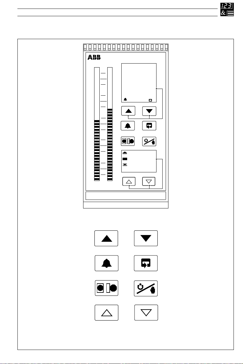
The COMMANDER 500 front panel displays, function keys and LED indicators are shown in Fig. 1.1.
COMMANDER 500
100
58.8
Raise
Alarm
Acknowledge
80
60
40
L
20
M OP1 OP2 FF
0
Function Keys
62.4
MST SLV
R
L
15.0
R
Lower
Parameter Advance
Local/Remote
Fig. 1.1 Front Panel Displays and Function Keys
L
R
L
Up Down
Auto/manual
3
Page 8
…1 DISPLAYS AND FUNCTION KEYS
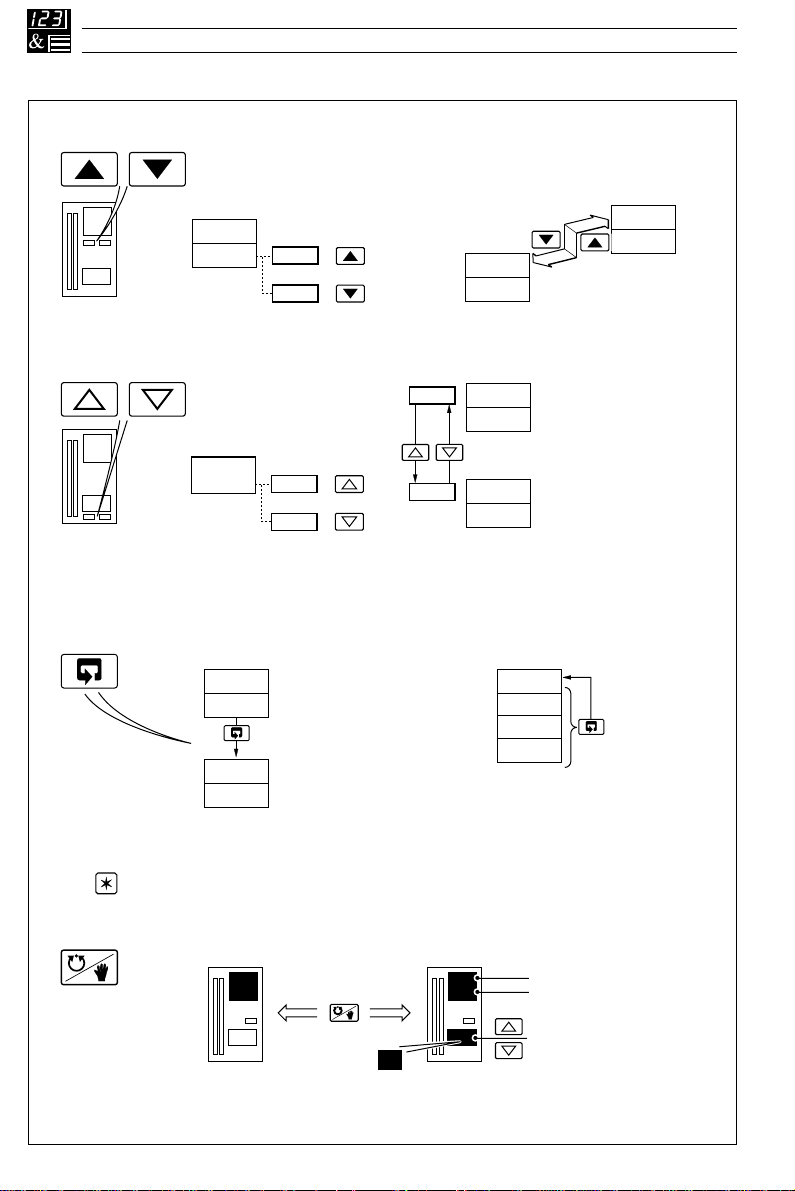
1.2 Use of Function Keys
A – Raise and Lower Keys
bIAS
+
50.0
Use to change/set a parameter value… …move between levelsand…
B – Up and Down Keys
700
Use to adjust the output value…
C – Parameter Advance Key
LEV2
tUnE
CYCl
51.0
49.0
–
+
710
690
–
and…
Frame 1
(top of level)
Frame 2
…move between frames within a Setup
or Configuration level. Any changes made
on the current frame are stored when the
next frame is selected.
5.0
2.00
2.01
LEV1
OPEr
LEV2
tUnE
CYCl
5.0
LEVx
1001
1002
1003
Frame 1
(top of level)
Frame 2
Press and hold
LEV2
tUnE
Note. This key also stores any changes made in the previous frame
D – Auto/Manual Key
4
Use to advance to the next
frame within a level…
Auto Manual
450.2
500.0
70
Use to select Auto or Manual control mode
Fig. 1.2a Use of Function Keys
or…
M
…select the top (LEV.x)
frame from within a level
450.2
500.0
70
Process Variable
Control Set Point
Control Output (%)
Page 9
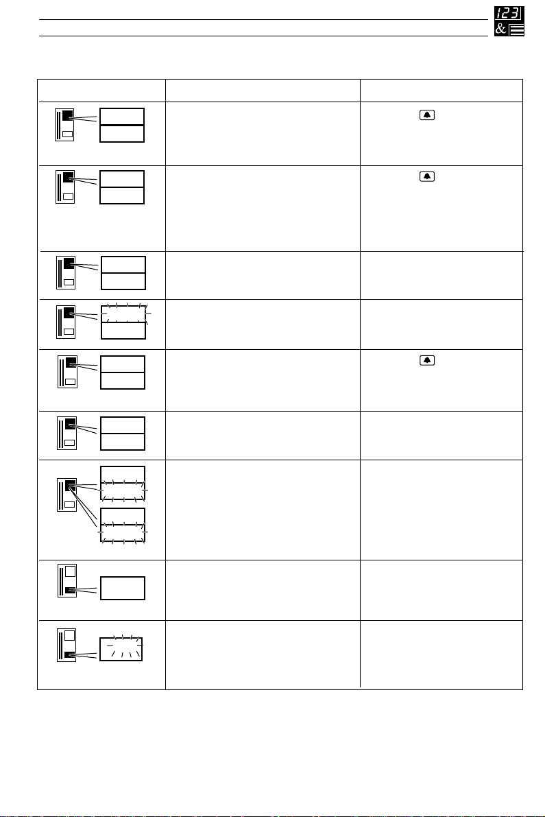
…1.2 Use of Function Keys
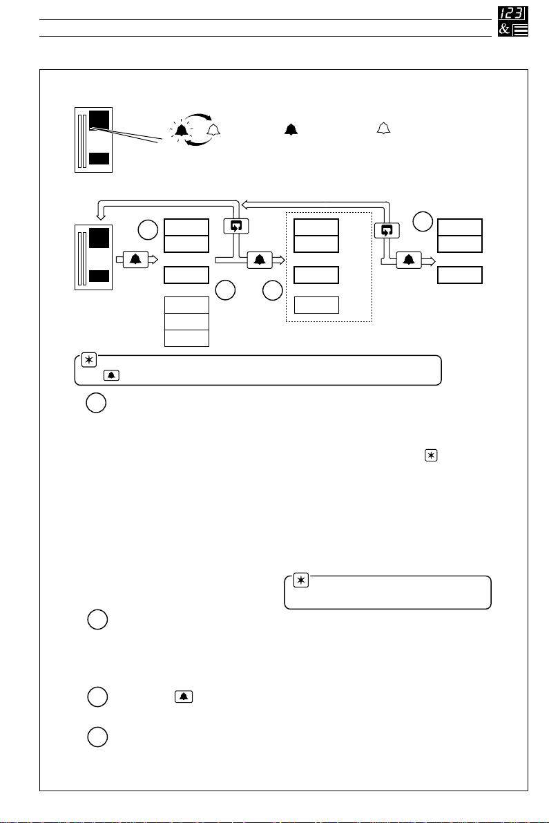
E – Alarm Acknowledgement
Any active,
unacknowledged
alarms
All active
alarms
acknowledged
(Flashing)
450.2
500.0
70
200.3
1.HP1
2003
1HP1
ACt
ACK
LAt
or
CLr
ACK
LAt
or
200.3
2.xxx
ACt
1
2
3
4
Unacknowledged
alarms only
450.2
500.0
70
(On continuously) (Off)
No active
alarms present
Pressing again acknowledges the displayed alarm.
Lower display changes to reflect new status.
3
Next active and unacknowledged alarm is displayed. If no alarms
are active, the next enabled alarm is displayed.
4
The first active and unacknowledged alarm is displayed
(or if no alarms are active, the first enabled alarm is displayed)
1
The lower display shows alarm status:
ACt
Alarm active and unacknowledged
ACK
Alarm active and acknowledged
CLr
Cleared or Inactive alarm
LAt
Unacknowledged latched alarm
2
Note. The time of the power failure
PF.t, is shown in the set point display.
High Process, PV High Output
Low Process, PV Low Output
High Latch, PV Power Failure Time
Low Latch, PV Maths Block 1 High
High Deviation Maths Block 1 Low
Low Deviation Maths Block 2 High
High Process I/P1 Maths Block 2 Low
Low Process I/P1 Maths Block 3 High
High Process I/P2 Maths Block 3 Low
Low Process I/P2 Maths Block 4 High
High Process I/P3 Maths Block 4 Low
Low Process I/P3
HPV HO
LPV LO
HLP PF.t
LLP Hb1
Hd Lb1
Ld Hb2
HP1 Lb2
LP1 Hb3
HP2 Lb3
LP2 Hb4
HP3 Lb4
LP3
Note. If no alarms have been enabled in the Set Up level, pressing
the key has no effect.
1 DISPLAYS AND FUNCTION KEYS…
Fig. 1.2b Use of Function Keys
5
Page 10
…1 DISPLAYS AND FUNCTION KEYS
…1.2 Use of Function Keys
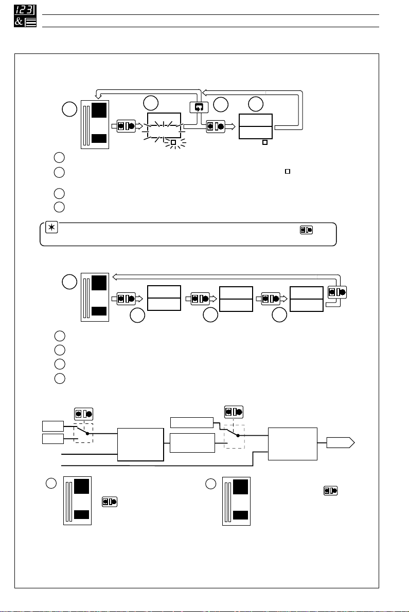
F – Local / Remote Key
Changing between Local and Remote Set Points
450.2
1
500.0
70
1
Process variable and local set point (ratio) displayed on red and green displays.
Remote set point (ratio) value is displayed. The value and symbol flash to
2
2
450.2
L
R
L
400.0
R
4
L
R
L
3
450.2
400.0
R
R
indicate local set point (ratio) still selected.
3
Remote set point (ratio) selected.
4
Remote selection aborted.
Note. When an Analog Backup Station template is selected, the key
L
is used to switch between local and remote mode – see Sections 2.4 and 4.2.
Selecting Local Set Points 1 to 4
450.2
1
350.0
70
Process variable and local set point 1 displayed.
1
Process variable and local set point 2 displayed
2
Process variable and local set point 3 displayed
3
4
Process variable and local set point 4 displayed
450.2
L
R
L
400.0
2
450.2
L
R
L
475.0
450.2
L
R
L
475.0
43
Selecting Master and Slave Set Points – Cascade Mode
Abbreviations are
detailed in Section 1.8.
Slave PID
Control Loop
When the SLV indicator (see
Fig 1.3) is lit, the key
can be used to switch
between the local slave
set point and the cascade
LSPt
RSPt
M.PV
S.PV
1
L
R
L
M.SPt
Master
Control Loop
450.2
When the MST indicator
350.0
(see Fig 1.3) is lit, the
L
R
L
key can be used to
switch between the Master
70
local and remote set points
PID
Local S.SPt
M.OP x
CrtO + CbIA
L
R
L
S.SPt
450.2
2
350.0
70
slave set point generated
from the master output.
R
L
L
R
L
OP1
L
R
L
Fig. 1.2c Use of Function Keys
6
Page 11
…1.2 Use of Function Keys
G – Short-cut Keys
1 DISPLAYS AND FUNCTION KEYS…
+
Press simultaneously and
hold for 3 seconds
LEVA
CntL
LEV1
OPEr
Press to move from anywhere in
the Configuration level to the first
frame in the Operator level
450.2
350.0
Press and hold to move from the Operator
Level to the Security Code Frame and then
to other levels:
70
Tune Level – See Section 2.13.3
Set Up Level – See Fig. 3.1
Configuration Level – See Fig. 4.1
COdE
0
LEV6
APPL
450.2
350.0
Press to move from
anywhere in the Operator
or Setup levels to the first
page of the Configuration
70
Note. This Short-cut key operates
only when the configuration password is
set to ‘0’
level
Fig. 1.2d Use of Function Keys
7
Page 12
…1 DISPLAYS AND FUNCTION KEYS
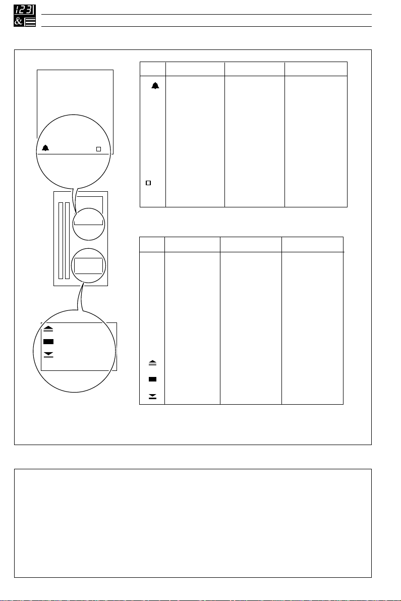
1.3 Secret-til-Lit Indicators
450.2
350.0
MST SLV
R
450.2
350.0
150
150
M OP1 OP2 FF
MST
SLV
R
M
OP1
OP2
FF
Flashing
One or more
alarms active and
unacknowledged
A – Upper Display
Flashing
Autotune in
progress
ON
All active alarms
acknowledged
Master controller
parameters
displayed
Slave controller
parameters
displayed
Remote or
Cascade set
point in use
ON
Manual control
selected
Output 1 (heat)
value displayed
Output 2 (cool)
value displayed
Feedforward
disturbance
variable displayed
Valve opening
Valve stopped
Valve closing
B – Lower Display
OFF
No alarms active
Local set point
in use
OFF
Auto control
selected
1.4 Character Set – Fig. 1.4
A
B
C
D
E
F
G
H
8
Fig. 1.3 Secret-til-lit Indicators
I
A
b
C
d
E
F
G
H
Fig. 1.4 Character Set
I
J
J
K
K
L
L
M
M
N
N
or
n
O
O
P
P
R
r
S
S
T
t
U
U
V
V
Y
Y
Page 13
1.5 Error Messages
1 DISPLAYS AND FUNCTION KEYS…
Display
70
70
70
70
70
70
70
or
CAL
Err
Err
NVx
A-d
Err
9999
t.Err
1
CJ.F
1
rSP.F
9999
rAt.F
9999
Error/Action
Calibration Error
Turn mains power off and on again
(if the error persists contact the
Customer Support Organization).
Non-volatile Memory Error
x = 1, 2: Motherboard Memory
x = 3: Option Board Memory
Turn mains power off and on again
(if the error persists, check
configuration/setup settings).
A to D Converter Fault
The analog to digital converter is not
communicating correctly.
Input Value Over/Under Range
Auto-tune Error
The number displayed indicates the
type of error present – see Table 2.1
on page 30.
Cold Junction Failed
Cold junction sensor is faulty or has
not been fitted correctly.
Remote Set Point or External
Ratio Failed. Remote set point input
value is over or under-range. Only
appears if the remote set point (or
external ratio) is displayed or in use.
To clear the display:
Press the key
Press the key
Contact the Customer
Support Organization
Restore valid input
Press the key
Check connections or replace
if faulty.
Restore valid input
StK
999
Valve Sticking
Motorized valve not moving at the
speed expected. Valve may be
sticking.
Position Feedback Fail
Input value is over- or under-range.
Only appears if output type set to
'PFb' – motorized valve with feebac k.
Check that the correct
Regulator Travel Time has
been set – see Section 3.5.
Check the valve.
Restore valid input
9
Page 14

…1 DISPLAYS AND FUNCTION KEYS
1.6 Processor Watchdog
The instrument's processor activity is monitored by an independent watchdog device. When the
output of the watchdog is assigned to a relay or digital output, the relay/digital output de-energizes
if the instrument fails to function correctly.
1.7 Loop Break Monitor
Both analog outputs are monitored continuously to detect a loop break. A warning signal or other
action can be initiated by assigning the loop break signals to relays or digital outputs.
1.8 Glossary of Abbreviations
noitaiverbbAnoitpircseDnoitaiverbbAnoitpircseD
VPelbairaVssecorP1id1tupnIlatigiD
tPSLeulaVtnioPteSlacoL2id2tupnIlatigiD
1PSLeulaV1tnioPteSlacoL3id3tupnIlatigiD
2PSLeulaV2tnioPteSlacoL4id4tupnIlatigiD
3PSLeulaV3tnioPteSlacoL1oa1tuptuOgolanA
4PSLeulaV4tnioPteSlacoL2oa2tuptuOgolanA
tPSCeulaVtnioPteSlortnoC1od1tuptuOlatigiD
tPSReulaVtnioPteSetomeR2od2tuptuOlatigiD
P/ODIPmhtiroglADIPehtfotuptuOVP.MelbairaVssecorPretsaM
1PO)taeh(1tuptuOrellortnoCtPS.MtnioPteSlortnoCretsaM
2PO)looc(2tuptuOrellortnoCPO.MtuptuODIPretsaM
1P/I1tupnIgolanAtPS.StnioPteSevalS
2P/I2tupnIgolanAVP.SelbairaVssecorPevalS
3P/I3tupnIgolanAVWelbairaVdliW
VDelbairaVecnabrutsiD
10
Table 1.1 Glossary of Abbreviations
Page 15
2 OPERATOR LEVEL
2.1 Introduction
The Operator level (Level 1) is the normal day-to-day mode of the COMMANDER 500. This section
describes the operator facilities available on each frame depending on the control template and
output type selected.
The template types detailed in this section are:
• Single loop controller
• Auto/Manual station
• Analog backup station
• Indicator/manual loader station
• Single loop with feedforward control
• Cascade control
• Cascade with feedforward
• Ratio controller
• Ratio station
Note. Only the frames relevant to the selected template are displayed – see Section 4.
In addition, frames used to view the Control Efficiency Monitor and operate motorized valve and heat/
cool output types are also described.
C501
01.SL
2001
01
Fig. 2.1 Power-up Displays
Model – C501
Template (see rear fold-out)
Software series
Software version
11
Page 16
…2 OPERATOR LEVEL
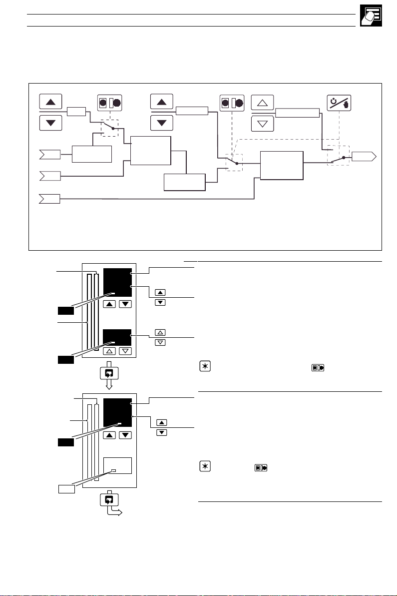
2.2 Single Loop Controller (Templates 1 and 2)
The single loop controller is a basic feedback control system using three-term PID or on/off control
with either a local set point (template 1) or remote set point (template 2).
L
Local Set Point
LSPt
LR
Remote Set Point Input
•1
I/P2
Process Variable Input
I/P1
•1 Template 2 Only
I/P2 x rAtO + bIAS
RSPt
CSPt
PV
Manual Output
PID
Control Loop
Fig. 2.2 Single Loop Controller
PID O/P
Control
Output
OP1
12
Page 17
…2.2 Single Loop Controller (Templates 1 and 2)
2 OPERATOR LEVEL…
Set Point
Process
Variable
Set Point
Process
Variable
OP1
OP1
•1
Process Variable
450.2
500.0
70
rAtO
•1
•2
Control Set Point
['SPLO' to 'SPHI' – see Section 4.5]
Adjustable in Local Control Only
Control Output
[0 to 100% (digital/relay outputs),
–10 to 110% (analog outputs)]
Adjustable in manual mode only. With on/off control
selected, 0% = control output off, 100% = control
output on. In manual mode, intermediate values can
be selected. These use 'time proportioning' with a
60s cycle time, e.g. 25% = 15s on, 45s off.
Remote Set Point Ratio
1.000
[0.001 to 9.999]
Remote set point value =
(ratio x remote set point input) + bias
70
Set Point
Process
Variable
bIAS
1.000
•3
Remote Set Point Bias
[In engineering units]
70
OP1
Return to top of page
•1 With the Ramping Set Point function enabled (see Section 3.3, Set Points/ Ramp Rate), the
bargraph shows the actual (ramping) set point value and the digital display shows the target set point
value.
•2 Only displayed if template 2 selected and Ratio Display is enabled – see Section 4.2, Basic
Configuration and Section 4.7, Operator Configuration.
•3 Only displayed if template 2 selected and Bias Display is enabled – see Section 4.2, Basic
Configuration and Section 4.7, Operator Configuration.
13
Page 18
…2 OPERATOR LEVEL
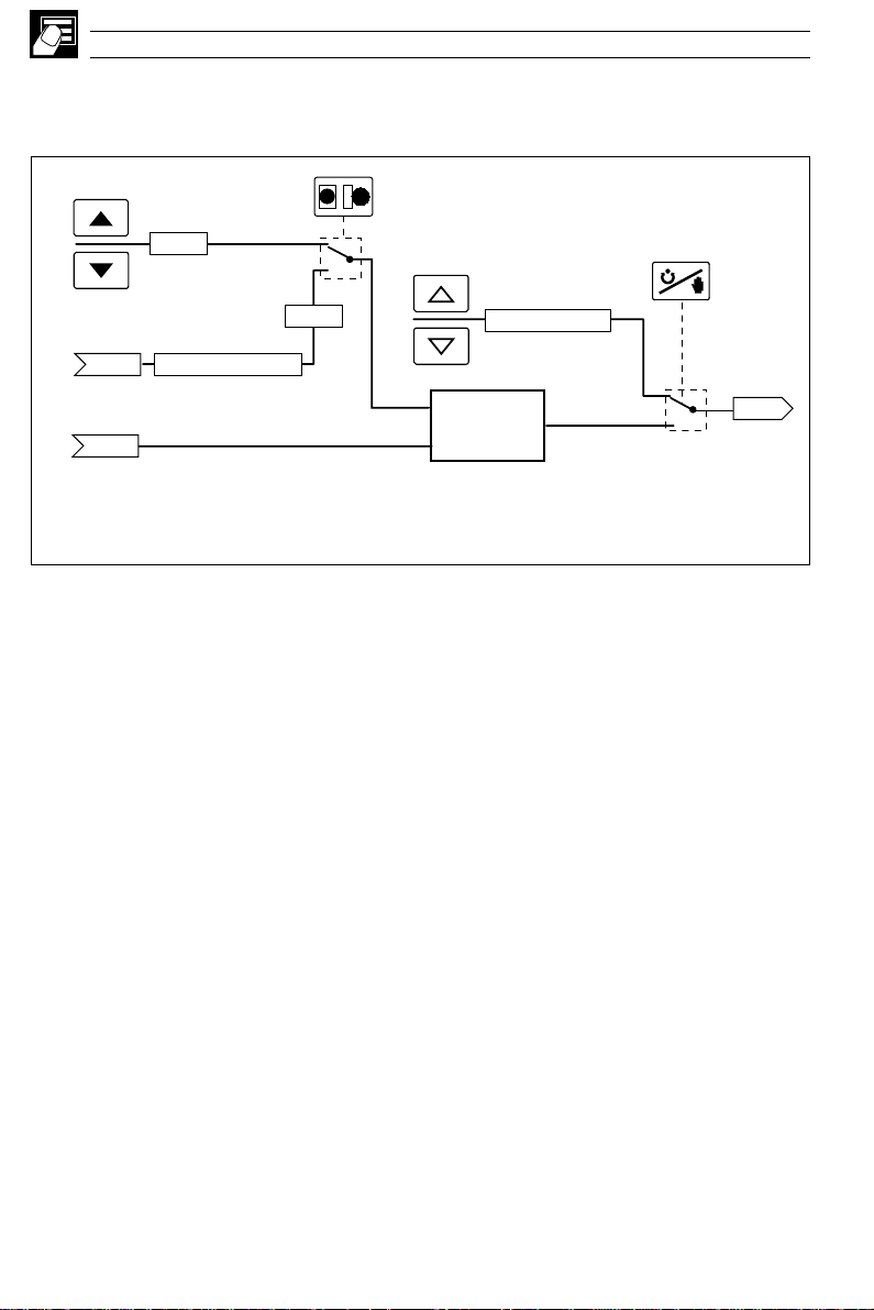
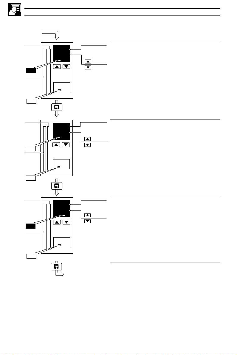
2.3 Auto/Manual Station (Templates 3 and 4)
Note. Refer also to Appendix A2.1 – Series and Parallel Operation.
The auto/manual station provides a backup for a master controller. In normal operation the
COMMANDER 500’s analog output follows the master controller’s output value. A fault in the master
system can be identified either by detecting a low signal on the master output (template 3) or via a
digital signal (template 4). When a fault is detected the COMMANDER 500 goes into manual mode
with its output either set to the last valid master output value or to a configured output value – see
Section 4.6, Control Configuration/ Configured Output 1. When the master output is restored or the
digital input returns to its inactive state, the COMMANDER 500 switches back to auto mode.
Note. The Alarm A1 Trip value must be set when using template 3.
Manual Output
Master Output
I/P2
Digital Select
di1
•1 Template 3 Only
•2 Template 4 Only
Low Signal Select
(Alarm A1)
•1
•2
Fig. 2.3 Auto/Manual Station
Analog Output
ao1
Auto / Manual
Select
14
Page 19
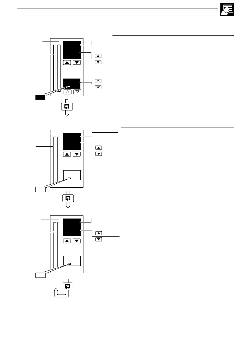
…2.3 Auto/Manual Station (Templates 3 and 4)
2 OPERATOR LEVEL…
Master
output
Process
Variable
•1
•2
Low Master
Output Value
•3
Digital Input
Active
Master
output
Process
Variable
or
or
55.0
50.0
70
55.5
50.0
•1
or
•2
Restored
Master Output
or
•3
Digital Input
Inactive
Auto Mode
Process Variable
Master Output (I/P2)
Control Output = Master Output
[Master Output, 0 to 100%]
Manual Mode
50
M
•1 In template 4 the Auto/Manual switch is overridden by the digital input signal.
•2 Template 3 only – see Section 4.2, Basic Configuration/ Template Application.
•3 Template 4 only – see Section 4.2, Basic Configuration/ Template Application.
Control Output (under COMMANDER 500 control)
[0 to 100%]
15
Page 20
…2 OPERATOR LEVEL
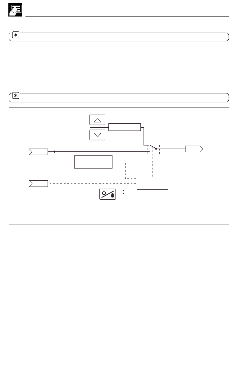
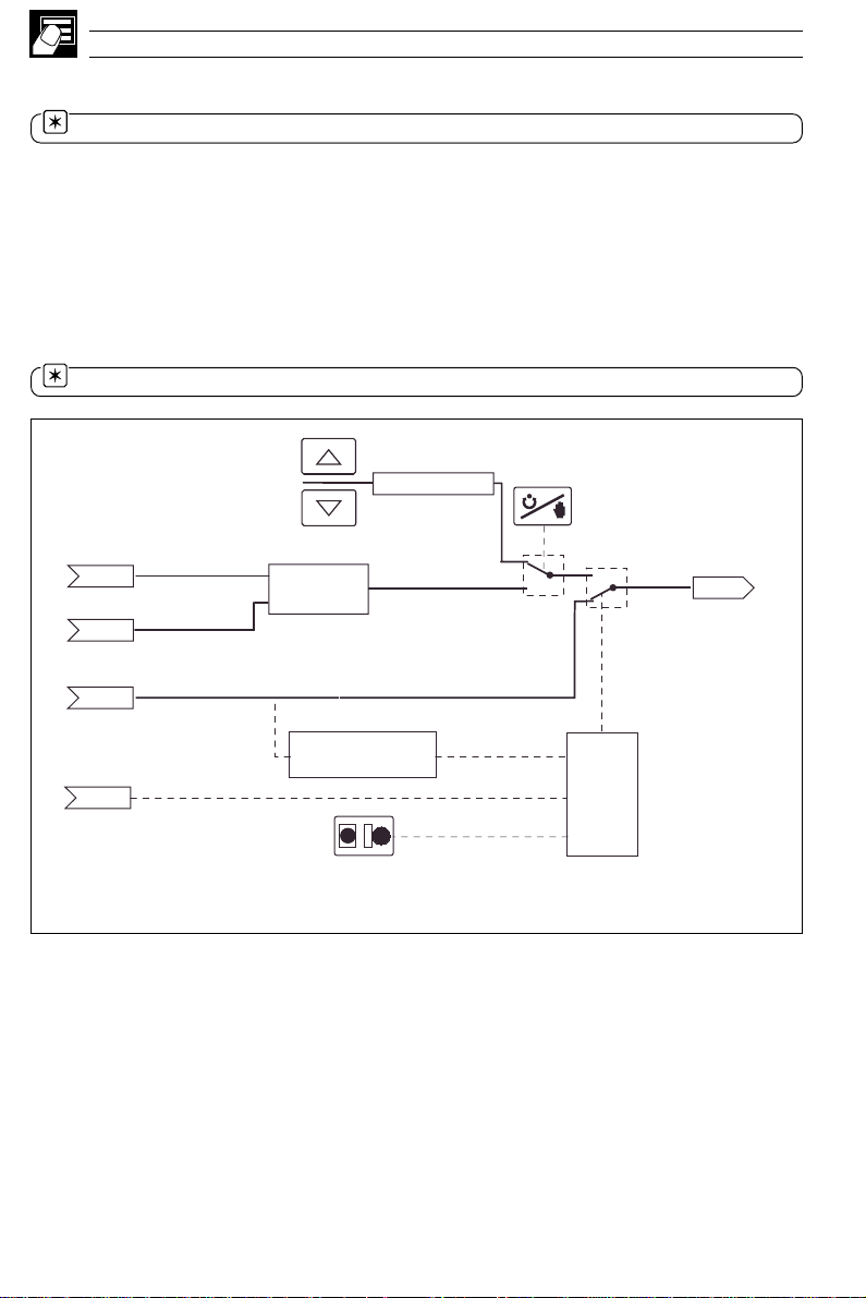
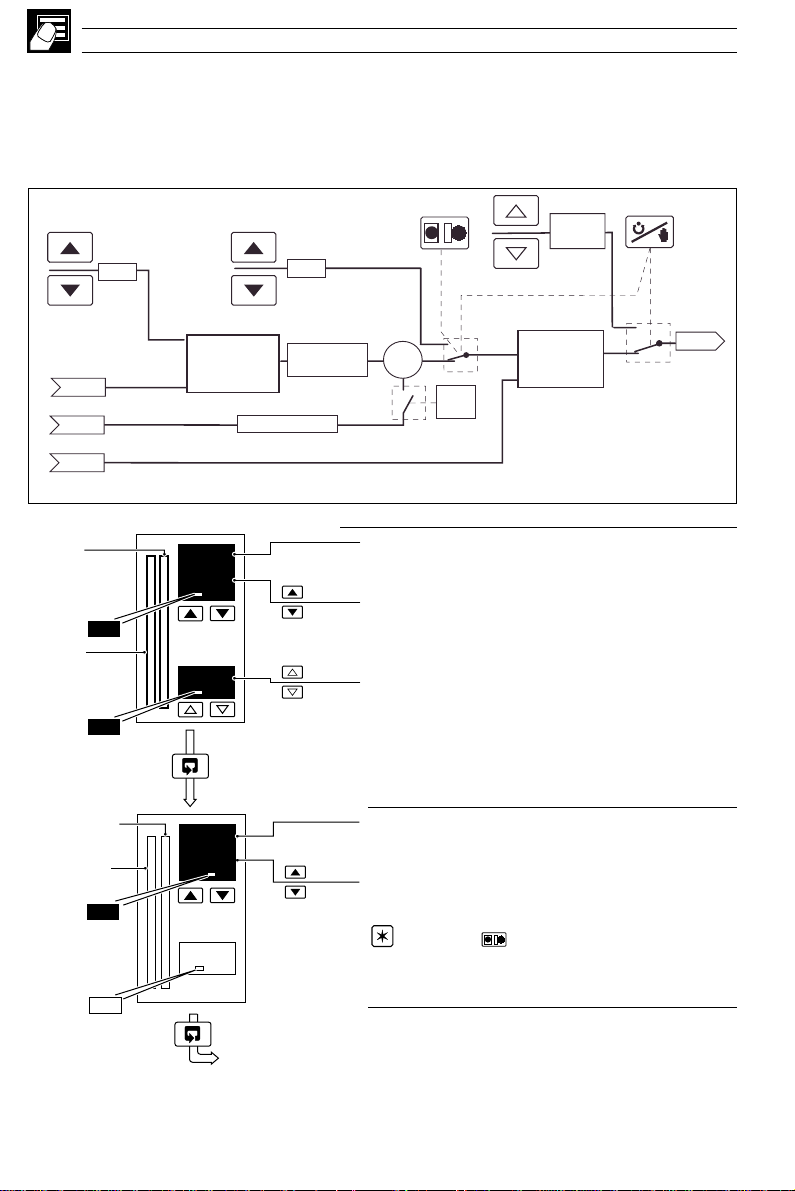
2.4 Analog Backup (Templates 5 and 6)
Note. Refer also to Appendix A2.1 – Series and Parallel Operation.
The analog backup station provides a backup for a master controller. In normal operation (remote
control mode selected) the COMMANDER 500’s current output follows the master controller’s output
value. A fault in the master system can be identified either by detecting a low signal on the master
output (template 5) or via a digital signal (template 6). When a fault is detected the COMMANDER
500 switches into local control mode and the process is controlled by the PID output of the
COMMANDER 500. The COMMANDER 500 PID algorithm tracks the master output value
continuously in order to ensure bumpless transfer from remote to local mode operation. When the
master output is restored or the digital input returns to its inactive state, the COMMANDER 500
switches back to remote control mode.
Note. The Alarm A1 Trip value must be set when using template 5.
Manual Output
Local Set Point
LSPt
Process Variable
I/P1
Master Output
I/P2
Digital Select
di1
•1 Template 5 Only
•2 Template 6 Only
PID
Control Loop
PV
Low Signal Select
(Alarm 1)
L
LR
Fig. 2.4 Analog Backup Station
•1
•2
Local/
Remote
Select
Analog Output
ao1
16
Page 21
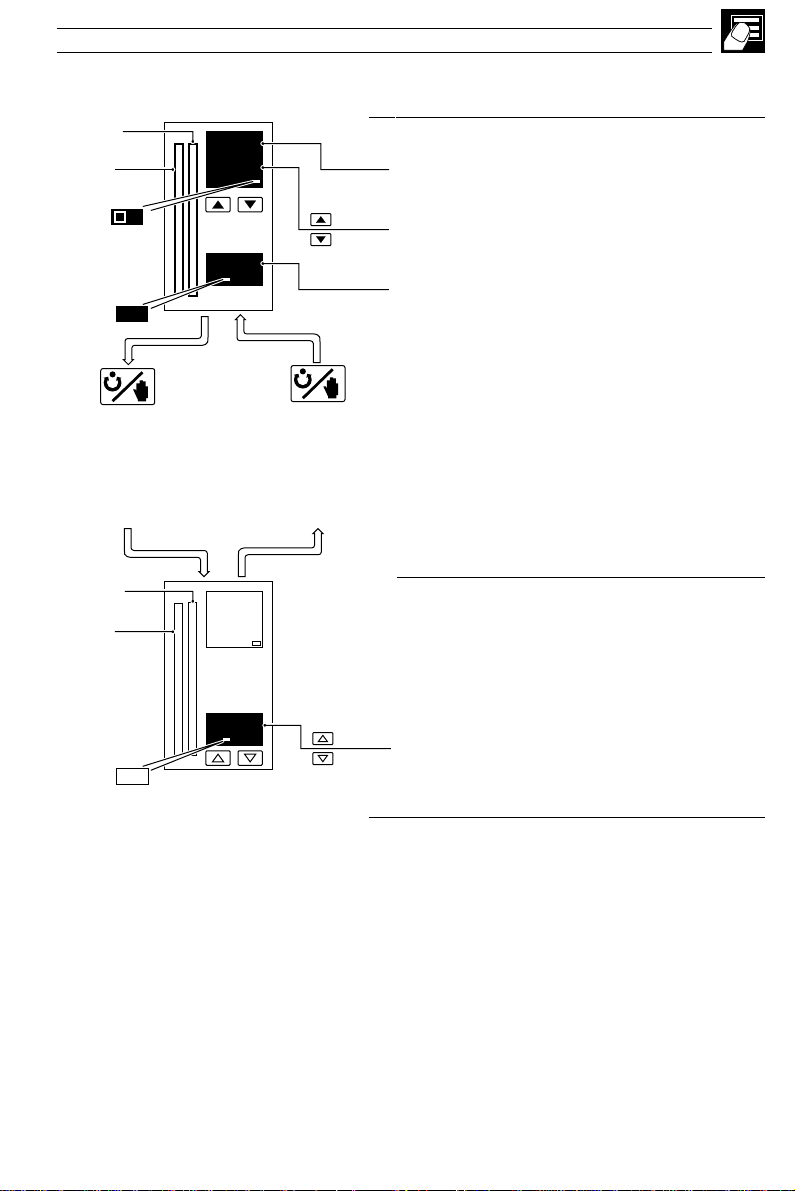
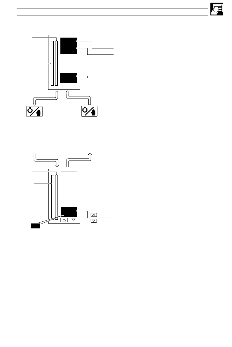
…2.4 Analog Backup (Templates 5 and 6)
2 OPERATOR LEVEL…
Set Point
Process
Variable
•1
•2
Set Point
Process
Variable
R
OP1
or
Low Master
Output Value
or
Digital Input
Active
55.0
50.0
70
55.5
50.0
or
•1
Restored
Master Output
or
•2
Digital Input
Inactive
Remote Mode
Process Variable
Set Point
['SPLO' to 'SPHI' – see Section 4.5]
Control Output = Master Output
[Master Output, 0 to 100%]
Local Mode
50
OP1
•1 Template 5 only – see Section 4.2, Basic Configuration/ Template Application.
•2 Template 6 only – see Section 4.2, Basic Configuration/ Template Application.
Control Output (under COMMANDER 500 control)
[0 to 100%]
Adjustable in Manual Mode only.
17
Page 22

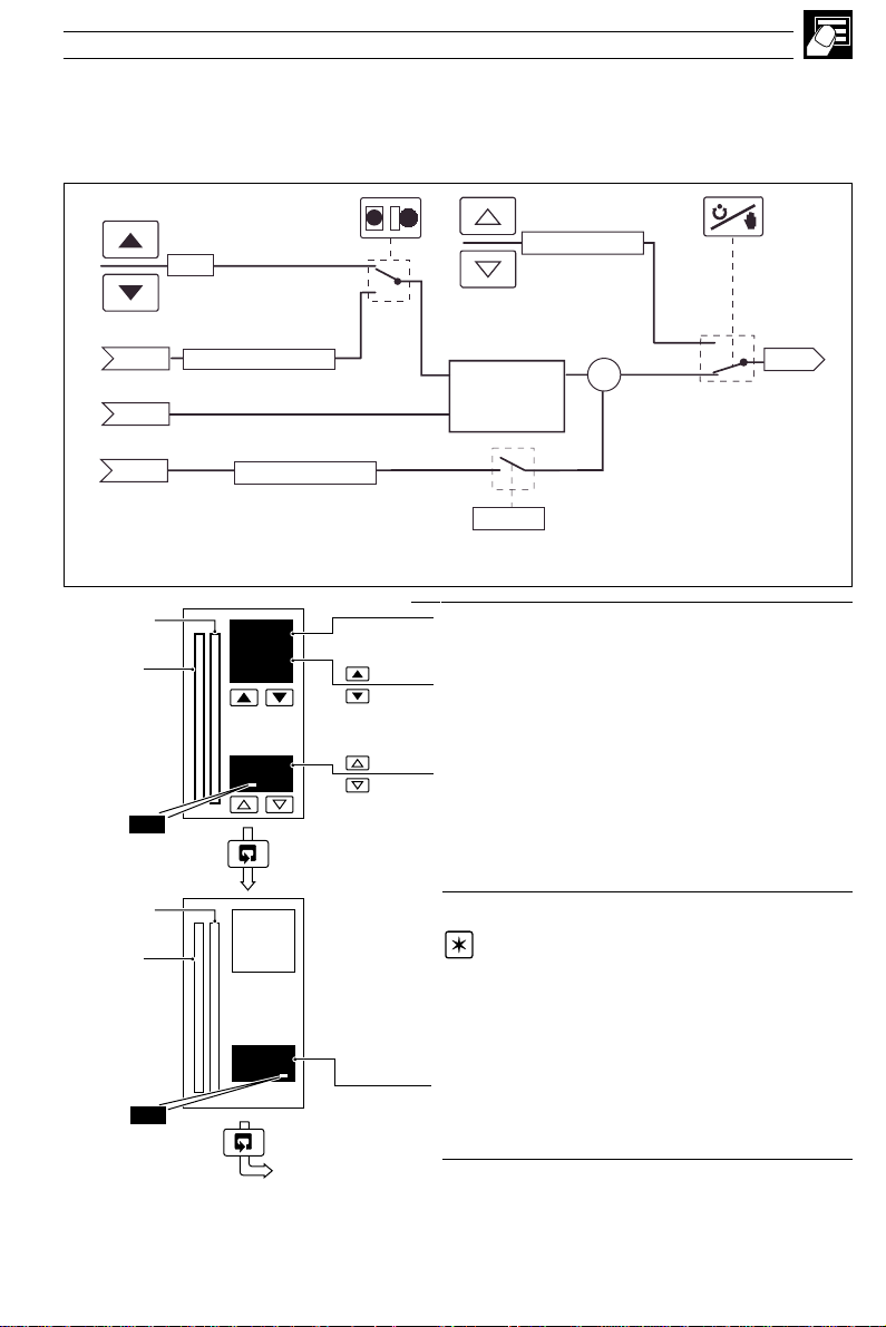
…2 OPERATOR LEVEL
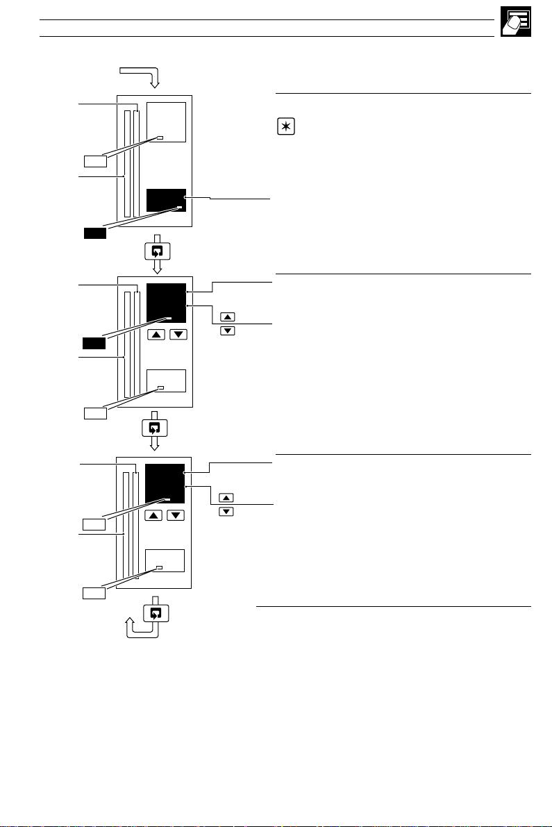
2.5 Indicator/Manual Loader Station (Templates 7 and 8)
One or two process variables can be displayed on the digital and bargraph displays. If the control
output is assigned to an analog output, the lower display indicates its value which can be adjusted by
the user.
Process
Variable
(PV2)
Process
Variable
(PV1)
OP1
•1
55.0
50.0
•1
50
•2
Process Variable PV1
Process Variable PV2
Output Value
[–10 to 110%]
•1 Only displayed if template 8 selected – see Section 4.2, Basic Configuration/
Template Application.
•2 Only displayed if control output type is 'analog' (output is assigned to Analog Output 1).
18
Page 23
2 OPERATOR LEVEL…
2.6 Single Loop with Feedforward (Templates 9 and 10)
These templates provide three-term PID control with feedforward. The disturbance variable is
weighted by the feedforward gain (FFGn) and the feedforward bias (FFbS) values and added to the
controller output value.
L
Local Set Point
LSPt
LR
Manual Output
Remote Set Point input
•1
PV input
Feedforward Disturbance Variable
I/P2
•1 Template 10 Only
I/P3
I/P1
RSPt x rAtO + bIAS
Control
Set Point
Process
•1
450.2
500.0
Variable
OP1
Control
Set Point
Process
450.2
500.0
Variable
CSPt
∑
PID O/P +
(DV x FFGn + FFbS)
DV x FFGn + FFbS
MPV
PID
Control Loop
FFGN = 0
Fig. 2.5 Single Loop Controller with Feedforward
Process Variable
Control Set Point
•1
['SPLO' to 'SPHI' – see Section 4.5]
Adjustable in Local control only.
Control Output
70
[0 to 100%]
Adjustable in Manual control only.
Feedforward
Note. To disable feedforward action (e.g.
during system tuning), set the Feedforward Gain
parameter to 0FF – see Section 3.2, Tune/Level 2 –
Tune.
OP1
50
[0 to 100%]
FF
•1 With the Ramping Set Point function enabled (see Section 3.3, Set Points/ Ramp Rate), the
bargraph shows the actual (ramping) set point value and the digital display shows the target set point
value.
Feedforward disturbance variable signal.
Continued…
19
Page 24
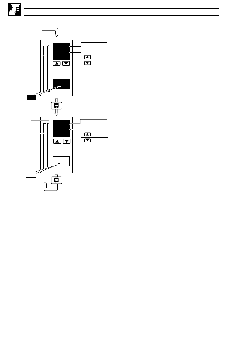
…2 OPERATOR LEVEL
…2.6 Single Loop with Feedforward (Templates 9 and 10)
Set Point
Process
Variable
Set Point
Process
Variable
OP1
OP1
rAtO
1.000
70
bIAS
0. 0
70
•1
•1
Remote Set Point Ratio
[0.001 to 9.999]
Remote set point value =
(ratio x remote set point input) + bias
Remote Set Point Bias
[In engineering units]
Return to Process Variable display
•1 Only displayed if template 10 selected – see Section 4.2, Basic Configuration/Template
Application and Section 4.7, Operator Configuration/Operator Ratio Display and Operator Bias
Display.
20
Page 25
2 OPERATOR LEVEL…
2.7 Cascade Control (Templates 11 and 12)
For cascade control, two internally-linked PID controllers are used, with the first (master) PID
controller providing the set point for the second (slave) controller. The master output is weighted
using the cascade ratio (C.rtO) and bias (C.bIA) values to create the slave set point value.
Local
Set Point
LSPt
Remote Set Point
input
•1
I/P3
Master PV Input
I/P1
Slave PV Input
I/P2
•1 Template 12 Only
Master
Set Point
(MSPt)
MST
Master
Process
Variable
(MPV)
OP1
RSPt x
RSPt
rAtO + bIAS
•1
L
LR
MPV
SPV
450.2
500.0
70
Slave Set
Point
SSPt
Master
Control Loop
PID
M.OP
M.OP x
CrtO + CbIA
Fig. 2.6 Cascade Controller
Master Process Variable (MPV)
•1
Master Control Set Point (MSPt)
['SPLO' to 'SPHI' – see Section 4.5]
Adjustable in local control only.
Slave Control Output
[0 to 100%] (–10 to 110% for analog outputs)
Adjustable in manual mode only.
to change between local/remote set point values.
L
LR
SSPt
Manual Output
Slave PID
Control Loop
Note. With template 12 the
L
R
L
key can be used
OP1
Slave
Set Point
(SSPt)
450.2
500.0
Slave Process Variable (SPV)
Slave Set Point (SSPt)
['SPLO' to 'SPHI' – see Section 4.5]
Slave
Process
Variable
(SPV)
SLV
70
OP1
Adjustable in manual or local slave set point modes
only.
L
R
Note. The
L
key can be used in this frame to
change between cascade and local slave set points.
Continued…
•1 With the Ramping Set Point function enabled (see Section 3.3, Set Points/ Ramp Rate), the
bargraph shows the actual (ramping) set point value and the digital display shows the target set
point value.
21
Page 26
…2 OPERATOR LEVEL
…2.7 Cascade Control (Templates 11 and 12)
Master
Set Point
(MSPt)
Master
Process
Variable
(MPV)
Master
Set Point
(MSPt)
Master
Process
Variable
(MPV)
Slave
Set Point
(SSPt)
Slave
Process
Variable
(SPV)
MST
OP1
MST
OP1
SLV
OP1
rAtO
1.000
70
bIAS
0. 0
70
C.rtO
1.000
70
•1
•1
•2
Remote Set Point Ratio
[0.001 to 9.999]
Master remote set point value =
(ratio x remote set point input) + bias
Remote Set Point Bias
[in engineering units]
Cascade Slave Set Point Ratio
[0.001 to 9.999]
Slave set point (SSPt) value =
(ratio x master ouput) + bias [in engineering units]
Continued…
•1 Only displayed if template 12 selected and ratio/bias display enabled – see Section 4.2, Basic
Configuration and Section 4.7, Operator Configuration.
•2 Only displayed if ratio/bias display enabled – see Section 4.7, Operator Configuration.
22
Page 27

…2.7 Cascade Control (Templates 11 and 12)
2 OPERATOR LEVEL
Slave
Set Point
(SSPt)
Slave
Process
Variable
(SPV)
SLV
OP1
C.bIA
0. 0
70
•1
Cascade Slave Set Point Bias
[In engineering units]
Return to Master Process Variable (MPV) display
•1 Only displayed if ratio/bias display enabled – see Section 4.7, Operator Configuration.
23
Page 28
…2 OPERATOR LEVEL
2.8 Cascade with Feedforward (Template 13)
For cascade control, two internally-linked PID controllers are used, with the first (master) PID
controller providing the set point for the second (slave) controller. The feedforward disturbance
variable signal is added to the master output (slave set point). The disturbance signal is weighted by
the feedforward gain (FFGn) and the feedforward bias (FFbs) values.
Local Set Point
LSPt
MSPt
Master PV Input
I/P1
Feedforward Disturbance Variable
I/P3
Slave PV Input
I/P2
Master
Set Point
(MSPt)
MST
MPV
SPV
•1
450.2
500.0
Master
Process
Variable
(MPV)
OP1
L
R
L
FFGn
= 0
SSPt
∑
Master
PID
Control Loop
DV x FFGn + FFbS
Local Slave
Set Point
SSPt
M.OP x
CrtO + CbiA
Fig. 2.7 Cascade Controller with Feedforward
Master Process Variable (MPV)
•1
Master Control Set Point (MSPt)
['SPLO' to 'SPHI' – see Section 4.5]
Adjustable in Local control only
Slave Control Output
70
[0 to 100% (–10 to 110% for analog outputs)]
Adjustable in Manual mode only.
Manual
Output
Slave
PID
Control Loop
OP1
Slave
Set Point
(SSPt)
1997
2000
Slave Process Variable (SPV)
Slave Set Point (SSPt)
['SPLO' to 'SPHI' – see Section 4.5]
Adjustable in Manual mode only
L
R
Note. The
L
key can be used in this frame to
change between cascade and local slave set points.
Slave
Process
Variable
SLV
70
(SPV)
OP1
Continued…
•1 With the Ramping Set Point function enabled (see Section 3.3, Set Points/ Ramp Rate), the
bargraph shows the actual (ramping) set point value and the digital display shows the target set point
value.
24
Page 29
…2.8 Cascade with Feedforward (Template 13)
2 OPERATOR LEVEL…
Master
Set Point
(MSPt)
Master
Process
Variable
(MPV)
Slave
Set Point
(SSPt)
Slave
Process
Variable
(SPV)
Slave
Set Point
(SSPt)
Slave
Process
Variable
(SPV)
MST
FF
SLV
OP1
SLV
OP1
450.2
500.0
50
C.rtO
1.000
70
C.bIA
0. 0
70
Feedforward Disturbance Variable
Note. To disable feedforward action (e.g.
during system tuning), set the Feedforward Gain
parameter to 0FF – see Section 3.2, Tune.
[0 to 100%]
Feedforward disturbance variable input.
•1
•1
Cascade Slave Set Point Ratio
[0.001 to 9.999]
Slave set point (CSP2) value =
(ratio x master ouput) + bias [in engineering units]
Cascade Slave Set Point Bias
[In engineering units]
Return to Master Process Variable (MPV) display.
•1 Only displayed if enabled in Level B, Operator Configuration – see Section 4.7.
25
Page 30
…2 OPERATOR LEVEL
2.9 Ratio Controller (Templates 14 and 15)
Ratio control enables a controlled process variable to be maintained automatically in definite
proportion to another variable known as the wild variable. The wild variable, weighted by ratio (rAtO)
and bias (bIAS), values forms the control set point for the process variable.
L
LR
Local Ratio
•1
Remote Ratio
I/P3
Wild Variable
I/P2
Process Variable input
I/P1
•1 Template 15 only
Control
Set Point
Process
Variable
(PV)
OP1
Control
Set Point
Process
Variable
(PV)
55.0
50.0
70
bIAS
0. 0
70
rAtO
WV
WV
rAtO +bIAS
x
Fig. 2.8 Ratio Controller
•1
Manual Output
Control
CSPt
PV
PID
Control Loop
PID O/P
Output
OP1
Actual Ratio
Process Variable (PV) – Bias
=
Wild Variable (WV)
Desired Ratio
Adjustable in Local control only.
Control Set Point = (WV x Ratio) + Bias
Control Output
[0 to 100% (–10 to 110% for analog outputs)]
Adjustable in manual mode only.
Bias
[in engineering units]
OP1
Return to Actual Ratio display.
•1 Only displayed if enabled in Level B, Operator Configuration – see Section 4.7.
26
Page 31

2 OPERATOR LEVEL…
2.10 Ratio Station (Templates 16 and 17)
The ratio station provides a set point for a subsequent slave controller. The wild variable (WV) is
weighted by ratio (rAtO) and bias (bIAS) values and is then retransmitted as an analog output value.
L
LR
Local Ratio
•1
Remote Ratio
I/P3
Wild Variable
I/P2
•1 Template 17 only
rAtO
WV
Fig. 2.9 Ratio Station
Manual Output
rAtO +bIAS
WV x
Analog
Output
OP1
Wild
Variable (WV)
Process
Variable
(PV)
OP1
Variable (WV)
Process
Variable
(PV)
OP1
55.0
50.0
70
bIAS
0.0
70
Actual Ratio
Process Variable (PV) – Bias
=
Wild Variable (WV)
Desired Ratio
Adjustable in local control only.
Ratio Setpoint Output
= (WV x Ratio) + Bias
[–10 to 110%]
Adjustable in manual control only.
•1Wild
Bias
[In engineering units]
Return to Actual Ratio display.
•1 Only displayed if enabled in Level B, Operator Configuration – see Section 4.7.
27
Page 32

…2 OPERATOR LEVEL
2.11 Heat/Cool Output Types
2.11.1 Reverse (Heat)/Direct (Cool) or Direct (Heat)/Reverse (Cool)
The active output, either OP1 (Heat) or OP2 (Cool) is displayed and may be adjusted in manual
mode. The OP1 and OP2 l.e.d.s indicate which output is changing.
–100%
OP2 (cool)
0%
Y2.St Y1.St
Fig. 2.10 Typical Response – Reverse/Direct or Direct/Reverse Control Action
450.2
500.0
50
OP1
OP1 (heat)
Output Positive (Heat Output Active)
Heat output
[0 to 100% (0 to 110% in manual mode with analog
outputs)]
Adjustable in manual mode only.
Output Negative (Cool Output Active)
+100%
PID O/P
100%
28
OP2
–50
Cool output
[–100 to 0% (–110 to 0% in manual mode with
analog outputs)]
Adjustable in manual mode only.
Page 33

2 OPERATOR LEVEL…
2.11.2 Reverse (Heat)/Reverse (Cool) or Direct (Heat)/Direct (Cool)
It is not possible to view or adjust the heat/cool outputs directly. The PID output (0 to 100%), used to
calculate the heat (OP1) and cool (OP2) outputs, is displayed and may be adjusted in manual mode.
The OP1 and OP2 l.e.d.s indicate which output is changing.
100%
OP2
(cool)
0%
OP2 l.e.d. lit OP1 l.e.d. lit
Fig. 2.11 Typical Response – Reverse/Reverse or Direct/Direct Control Action
Y2.St
Y1.St
OP1
(heat)
PID O/P
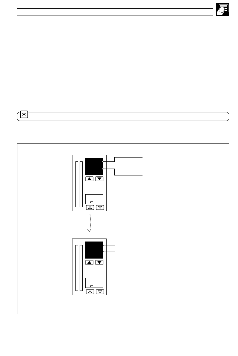
2.12 Motorized Valve Output Types
2.12.1 Motorized Valve with Feedback
450.2
Valve Position Display
500.0
[0 to 100% of travel]
75
Valve opening
Valve stopped
Valve closing
Note. In manual mode, the and keys
can be used to drive the valve open and valve close
relays directly.
100%
0%
2.12.2 Motorized Valve without Feedback (Boundless)
Valve State Display
OPN Valve opening
StP Valve stopped
StP
Valve opening
Valve stopped
Valve closing
CLS Valve closing
Note. In manual mode, the and keys
can be used to drive the valve open and valve close
relays directly.
29
Page 34

…2 OPERATOR LEVEL
2.13 Auto-tune
Note. Auto-tune is not available for Auto/Manual Station, Indicator or Ratio Station
templates, or when boundless or heat/cool control types are selected.
Information.
• Auto-tune optimizes process control by manipulating the COMMANDER 500 output and then
monitoring the process response.
• At the end of an auto-tune, the control parameters are updated automatically.
• Before starting auto-tune, the process variable must be stable.
• The COMMANDER 500 monitors the noise level of the process variable for 30 seconds and if
it is greater than 2% of the engineering range the auto-tune is aborted.
• The COMMANDER 500 selects either 'start-up' or 'at set point' tuning automatically, depending
upon the level of the process variable relative to the control set point.
2.13.1 Start-up Auto-tune
If the process variable is more than ±10% from the set point, 'start-up' tuning is carried out.
• 'Start-up' tuning – steps the output to drive the process towards the set point. The process
response to this step change is monitored and PID parameters are calculated.
• The output step applied = % deviation from the set point x 1.5.
• If no errors exist, the COMMANDER 500 enters auto mode and begins to control the process
using the new PID parameters.
• If an error occurs during the auto-tune, the COMMANDER 500 reverts to manual mode with the
control output set to the default output value. An error message is displayed in the operator
level – see Table 2.1.
1
PV
>10% span
+2%
– 2%
A – Stable process before auto-tune
SPT
PV
t
B – Process response during auto-tune
/4 wave
damping
Controlling to Set Point
Auto-tune complete
Fig 2.12a Typical 'Start-up' Auto-tune Cycles
rorrEnoitpircseDrorrEnoitpircseD
1enut-otuagniruddeliafVP7
2
pets
3enut-otuaotysionootssecorP9edomnoitarugifnocotnituprellortnoC
4enut-otuaottsafootssecorP01resuybdetanimretenut-otuA
5
6
.)selcyc-flahneewteb
enut-otuanagnirudtuodemitsahenut-otuA
8)enut-otua'putratS'(dedeecxetimilVP
sruoh21xam(enut-otuaotwolsootssecorP
11
.gne%52>ybtnioptesmorfdetaivedVP
tsetesnopserycneuqerfgnirudnaps
egnarfo
tsetpets
Table 2.1 Auto-tune Error Codes
30
SPT
t
tuodetaluclacsaweulavDroI,PtnatluserA
gnirudnoitceridgnorwehtnignignahcsiVP
Page 35

2 OPERATOR LEVEL…
2.13.2 'At Set Point' Auto-tune
If the process variable is within 10% of the set point, 'at set point' tuning is carried out.
• 'At set point' tuning – manipulates the control output to produce a controlled oscillation of the
process.
• A step change of ±10% of the starting output value is applied initially. This is adjusted to give an
amplitude of oscillation 3 times the noise level.
• Once the amplitude and period of oscillation are consistent (minimum 2 cycles, maximum 4
cycles) PID parameters are calculated.
• If no errors exist the controller enters auto mode and begins to control the process using the new
PID parameters.
• If an error occurs during the auto-tune, the controller reverts to manual mode with the control
output set to the default output value. An error message is displayed in the operator level –
see Table 2.1.
PV
+2%
– 2%
< ±10 span
A – Stable process before auto-tune
SPT
PV
t
B – Process response during auto-tune
12 hours max.
SPT
Controlling to
Set Point
Auto-tune
complete
t
Fig 2.12b Typical 'At Set Point' Auto-tune Cycles
Note. The time taken to complete auto-tune depends upon the system response time.
Notes For Special Cases.
Cascade Control – the slave loop must be tuned before the master loop. The slave must be
placed into local set point mode (cascade disabled) and the slave set point adjusted to the
required value prior to tuning.
Feedforward Control – during an auto-tune with a controller with feedforward the feedforward
signal is not applied. The feedforward gain and bias values are not changed by the auto-tune and
must be adjusted separately.
Time Proportioning – the cycle time must be set prior to running an auto-tune. The cycle time is
not changed by the auto-tune.
31
Page 36

…2 OPERATOR LEVEL
2.13.3 Auto-tune
1..xx
1.xx
1.xx
xxxx
xxxx
COdE
AtNE
OFF
Accessing the Auto-tune Facility
From any operating frame, press and hold the key
until the 'COdE' frame is displayed.
1
Set the correct auto-tune password.
Auto-tune Enable
Select the type of auto-tune required.
Single Loop Templates Cascade Templates
OFF – Off SLV.A – Slave type A
A – Type A SLV.b – Slave type B
b – Type B MSt.A – Master type A
MSt.b – Master type B
Auto-tune is started automatically when the key is
pressed.
Auto-tune can be stopped at any time by pressing the
key.
Note. Slave control loops only – place the slave
into local set point mode and adjust the set point to the
required value prior to autotuning.
32
PV
xxxx
xxxx
x
1
Type A –
x
2
1
wave damping
/
4
Note. P + I control only – set the derivative term
to 'OFF' in the Tuning Level – see Section 3.2.
Return to the Operating Level.
PV
Set point
x
1
2
=
4
x
1
Fig. 2.13 Autotune Types
Set Point
Type B – Minimum Overshoot
Page 37

2 OPERATOR LEVEL…
2.14 Control Efficiency Monitor
Note. With cascade control, the Control Efficiency Monitor is applicable only to the master
controller.
The Control Efficiency Monitor can be used either to compare the relative performance with different
tuning parameters, or when fine tuning the PID settings, to give optimum control.
When the set point is changed, auto mode is selected or following a power failure, input failure or a
large load disturbance, the control monitor performs a series of measurements to indicate the
effectiveness of the current control parameters.
General guidelines are shown in Table 2.2.
Parameter
Rate of
Approach
Overshoot
Decay Ratio
Settling Time
Error Integral
Ideal
Setting
Fast
Small
Small
Short
Small
Actual
Setting
Too slow
Too large
Too large
(Oscill-
atory)
Too long
Too large
Effect on Response
Action
• Decrease proportional band
• Decrease integral time
• Increase derivative time
• Increase proportional band
• Increase derivative time
• Increase proportional band
• Increase integral time
• Increase proportional band
• Decrease integral time
If large overshoot and
oscillatory then:
• Increase proportional band
• Increase integral time
• Increase derivative time
If slow approach and
overdamped then:
• Decrease proportional band
• Decrease integral time
Table 2.2 Control Efficiency Monitor Settings
33
Page 38

…2 OPERATOR LEVEL
…2.14 Control Efficiency Monitor
t
x
period
PV
y
2
1
95%
y
1
x
2
+2%
Set Point
–2%
t
Start of
Calculation
approach
t
settle
5%
t
Fig. 2.14 Control Efficiency Monitor Parameters
2.14.1 Manual Tuning
The Control Efficiency Monitor may be used for manually tuning the PID parameters. The following
method describes how to tune the controller for 1/4 wave damping:
a) Set the integral and derivative action times to OFF.
b) Set the proportional band (PB) to a low setting.
c) Apply a small set point change.
d) Use the Control Efficiency Monitor to note the decay ratio.
e) If the decay ratio > 0.25, increase the Proportional Band until decay ratio = 0.25
If the decay ratio < 0.25, decrease the Proportional Band until decay ratio = 0.25
f) Leave the proportional band at the setting which gives 0.25 decay ratio and, using the Control
Efficiency Monitor, note the period between peaks.
g) Calculate and set the following parameters:
Integral action time = Period/1.5
Derivative action time = Period/6
Note. The manual tuning facility must not be used with boundless motorized valve control, as
an Integral Action Time is required for these applications.
34
Page 39

2.14.2 Using the Control Efficiency Monitor
450.2
500.0
Press and hold the lower and keys for 2 seconds.
2 OPERATOR LEVEL…
70
+
rAtE
10.1
OVEr
10
rAtO
0.25
Prd
35
SEtL
0.3
Note.
If the front panel keys are not operated for 60 seconds whilst any
Control Efficiency Monitor frame is being displayed, the instrument
reverts to the first operating frame.
Rate of Approach to Set Point
The rate of change of the process variable between 5 and 95% of the
step change (Y2), measured in engineering units per minute.
Rate of approach =
Overshoot
The maximum error, expressed as a percentage of the set point.
Overshoot =
Decay Ratio
The ratio of the amplitude of the first and second overshoots.
Ratio =
Period
The time (in seconds) between the first two peaks (t
Settling Time
The time taken (in minutes) for the process variable to settle within
±2% of the set point value (t
Set Point
X2
X1
Y1
t
approach
X
1
x100
).
period
).
settle
450.2
500.0
IAE
2.1
Error Integral
The integral of the error value until the process variable settles to
within ±2% of the set point value in 'engineering-unit hours'.
t
Error integral =
Return to the first operating frame.
settle
|PV – SP|dt
0
35
Page 40

8
3 SET UP MODE
3.1 Introduction
To access the Set Up mode (Levels 2 to 5) the correct password must be entered in the security code frame.
Press
450.2
500.0
and hold
COdE
50
AtNE
OFF
LEV1
OPEr
LEV2
LEV3
70
450.2
500.0
70
LEV1
OPEr
Tuning
Cycle time, output 1 & 2
On/off hysteresis values
Proportional bands 1 to 4
Integral action times 1 to 4
Derivative action times 1 & 2
Manual reset value
Feedforward gain and bias
Control deadband
Heat Cool Output 1 & 2 Start
Set Points
Local set point values 1 to 4
Slave set point value
Remote set point ratio/bias
Cascade set point ratio/bias
Ramp rate
Fig. 3.1 Set Up Mode – Overview
Invalid
password
Valid Set Up or
Configuration
password
LEV2
tUNE
LEV4
LEV5
LEV5
VLVE
Alarm Trip Points
Alarm 1 to 8 trip points
Motorized Valve Set Up
With feedback:
Feedback ratio/bias
Deadband
Regulator travel time
Boundless:
Deadband
Regulator travel time
36
Frame number
2.xx
– Level 2
3.xx
– Level 3 etc.
450.2
500.0
2.00
2.00
2.01
Parameter
Fig. 3.2 – Scroll Display Overview
LEV.2
tUNE
CYC.1
1.0
Default
value
Parameter
adjustment
450.2
500.0
2.00
450.2
500.0
2.00
Page 41

3 SET UP MODE…
8
3.2 Level 2 – Tune
Note. Level 2 is not applicable if an Auto/Manual Station, Indicator or Ratio Station template is selected.
2.00
2.01
2.02
2.03
LEV.2
tUNE
CYC.1
1.0
CYC.2
1.0
HYS1
0
•1
•1
•2
•3
Level 2 – Tune
Note. To select this frame from anywhere in this page, press and
hold the
Cycle Time Output 1
[1.0 to 300.0 seconds for time proportioning or 'OnOF' for on/off control]
control or with cascade templates.
Cycle Time Output 2 (Cool)
[1.0 to 300.0 seconds for time proportioning or 'OnOF' for on/off control]
templates.
Output 1 On/Off Hysteresis Value
[In engineering units]
PV
ON
OFF
key for a few seconds.
Note. On/off Control is not available on output 1 with heat/cool
Note. On/off Control is not available on output 2 with cascade
Set Point
Hysteresis
Value
Reverse Acting
Control Output
PV
ON
OFF
2.00...2.04
Hysteresis
Value
Set Point
Direct Acting
Control Output
2.04
HYS2
•4
0
•1 Only displayed if Relay or Digital output type is selected – see Section 4.2, Basic Configuration/ Output Type.
•2 Only displayed if Heat/Cool output type is selected.
•3 Only if On/Off control is selected – see parameters 2.01 and 2.02 above.
•4 Only displayed if Heat/Cool output type is select and the 'CYC.2' parameter is set to 'OnOF'.
Output 2 On/Off Hysteresis Value
[0% to (Y1.St – Y2.St)%] – see parameters 2.22 and 2.23
100%
Output 2
Hys 2
Y2.St
Continued on next page
Y1.St
Output 1
PID Output
37
Page 42

8
…3 SET UP MODE
…3.2 Level 2 – Tune
2.05
Pb-1
•1
100.0
2.06
2.08
Pb-2
100.0
Pb-4
•1
•2
•3
100.0
2.09
IAt.1
OFF
2.10
IAt..2
•2
OFF
2.05...2.13
Proportional Band 1
Enter the value for Proportional Band 1.
[0.1% to 999.9%]
'Pb-1' is the default proportional band and is the proportional band for the
master controller if a cascade template is selected – see Section 4.2 Basic
Configuration/ Template Application.
Proportional Band 2, 3 and 4
Enter the value for Proportional Band 2, 3 and/or 4.
[0.1% to 999.9%]
'Pb-2' is the proportional band for the slave controller if a cascade
template is selected – see Section 4.2, Basic Configuration/ Template
Application.
Integral Action Time 1
[1 to 7200 seconds or 'OFF']
'IAt.1' is the default integral action time and is the integral action time for
the master controller if a cascade template is selected – see Section 4.2,
Basic Configuration/ Template Application.
Integral Action Time 2, 3 and 4
[1 to 7200 seconds or 'OFF']
2..12
IAt.4
•3
OFF
2.13
drV1
OFF
•1 Heat/cool outputs use a common proportional band. The default is 'Pb-1'.
•2 Only displayed if a cascade template or a tune parameter source is selected – see Section 4.2, Basic
Configuration/ Template Application and Section 4.6, Control Configuration/ Tune Parameter Source.
•3 Only displayed if a tune parameter source is selected – see section 4.6, Control Configuration/ Tune
Parameter Source.
38
'IAt.2' is the integral action time for the slave controller if a cascade
template is selected – see Section 4.2, Basic Configuration/ Template
Application.
Derivative Action Time 1
[0.1 to 999.9 seconds or 'OFF']
'drV.1' is the derivative action time for the master controller if a cascade
template is selected – see Section 4.2, Basic Configuration/ Template
Application.
Continued on next page.
Page 43

3 SET UP MODE…
8
…3.2 Level 2 – Tune
2.14
drV2
•1
OFF
2.15
Ab.1
•2
1.0
2.16
Ab.2
•1
1.0
2.17
rSt.1
•3
50.0
2.18
rSt.2
•1
50.0
2.14...2.19
Derivative Action Time 2
[0.1 to 999.9 seconds or 'OFF']
The derivative action time for the slave controller if a cascade template is
selected – see Section 4.2, Control Configuration/ Template Application.
Approach Band 1
[0.1 to 3.0 proportional bands]
This parameter limits when derivative action time 1 is applied. When the
process variable is outside the approach band, derivative action is not applied.
•2
•3
Approach Band 2
[0.1 to 3.0 proportional bands]
This parameter limits when derivative action time 2 is applied to the slave
control loop when a cascade template is selected.
Manual Reset Value 1
The value applied to bring the master control output to the zero error point
under normal load conditions (integral action disabled) or the offset
applied to the control output (integral action enabled).
[0.0 to 100%]
Note. Manual reset is applied whether or not an integral action time
is set.
Manual Reset Value 2
As
Manual Reset Value 1, but applied to the slave output.
[0.0 to 100%]
Note. Manual reset is applied whether or not an integral action time
is set.
2.19
FFGn
•4
1.0
•1 Only displayed if a cascade template is selected – see Section 4.2, Basic Configuration/ Template Application.
•2 Not displayed if the associated derivative action time is set to OFF.
•3 If manual control is selected and no integral action time is set, the manual reset value is calculated
automatically to give bumpless transfer into auto control.
•4 Only displayed if a feedforward template is selected – see Section 4.2, Basic Configuration/ Template Application.
Feedforward Gain
The feedforward value applied to the control output is: (disturbance
variable x feedforward gain) + bias. When set to OFF, feedforward action
is disabled.
[0.1 to 999.9 or OFF]
Note. The feedforward value is normally added to the PID output. Using
the PC Configurator, the value can also be multiplied by the PID output.
Continued on next page.
39
Page 44

8
…3 SET UP MODE
…3.2 Level 2 – Tune
2.20
FFbS
•1
0.0
2..21
Cbnd
OFF
2...22
Y1.St
•2
50.0
2.20...2.23
Feedforward Bias
[–100.0% to 100.0%]
Control Deadband
When the process variable is in the deadband, changes to the control
output due to proportional and integral action are suppressed. When a
cascade template is selected, the control deadband is applied to the
master output only.
[In engineering units or 'OFF']
Set Point
Process Variable
Heat/Cool Output 1 Start
This parameter defines the PID output value above which Output 1 (heat)
becomes active.
[0.0 to 100.0%]
Deadband
Control Output
2...23
Y2.St
50.0
Reverse-direct
Output 2
0%
or direct-reverse
Y2.St Y1.St
PID Output
Output 1
100%
100%
0%
100%
0%
•2
Heat/Cool Output 2 Start
This parameter defines the PID output value below which Output 2 (cool)
becomes active.
[0.0 to ≤ Y1st %] – see Heat/Cool Output 1
Output 2
0%
Reverse-reverse
or direct-direct
Y2.St Y1.St
PID Output
Output 1
100%
LEV2
tUNE
Return to top of page
•1 Only displayed if a feedforward template is selected – see Section 4.2, Basic Configuration/ Template Application.
Not applied to Control Output when Feedforward Gain (frame 2.19) is set to 'OFF'.
•2 Only displayed if a Heat/Cool output type is selected – see Section 4.2, Basic Configuration/ Output Type.
40
Page 45

3 SET UP MODE…
8
3.3 Level 3 – Set Points
Note. Level 3 is not applicable if Auto/Manual Station or Indicator templates are selected.
3.00
3.01
3.02
3.04
3.05
LEV.3
SEtP
LSP1
500
LSP2
200
LSP4
400
S.SPt
300
•1
•1
•2
•1
•2
•3
Level 3 – Set Points
Note. To select this frame from anywhere in this page, press and
hold the
Local Set Point Value 1
Set the default local set point value.
[Within set point high and low limits, in engineering units – see Level 9]
Local Set Point Values 2 to 4
[Within set point high and low limits, in engineering units – see Level 9]
Cascade Slave Set Point Value
Set the slave set point value.
[Within slave set point high and low limits, in engineering units]
Only adjustable in Manual mode.
key for a few seconds.
3.00...3.07
3.06
rAtO
•4
1.000
3.07
BIAS
•4
0
•1 Not displayed for ratio controller or ratio station templates.
•2 Displayed only if a local set point source is selected – see Section 4.5/ Set Point Configuration/ Local/Remote
Set Point Source.
•3 Only displayed if a cascade template is selected.
•4 Displayed only for templates with a remote set point.
Remote Set Point Ratio
The remote set point value is
(ratio x remote set point input) + bias.
[0.001 to 9.999]
Remote Set Point Bias
[In engineering units]
Continued…
41
Page 46

8
…3 SET UP MODE
…3.3 Level 3 – Set Points
3.08
C.rtO
•1
1.000
3.09
C.bIA
•1
0
3.10
r.rtE
OFF
LEV3
SEt.P
3.08...3.10
Cascade Set Point Ratio
In automatic mode, the slave set point value is:
(ratio x master output) + bias.
[0.001 to 9.999]
Cascade Set Point Bias
[In engineering units]
Ramp Rate
[1 to 9999 engineering units per hour, or OFF]
The Ramping Set Point facility can be used to prevent a large disturbance
to the control output when the set point value is changed. The rate set
applies to both the local and the remote set points.
PV
300
200
100
0
* e.g. Ramp Rate = 200 Increments/Hour
Displayed Local Set Point Value
Actual (Ramping) Set Point Value
used by PID Algorithm*
1 Hour
Time
Return to top of page.
•1 Displayed only if a Cascade template is selected – see Section 4.2, Basic Configuration/ Template Application.
42
Page 47

3 SET UP MODE…
8
3.4 Level 4 – Alarm Trip Points
Note. Level 4 is not applicable if all alarm types are set to 'None' – see Section 4.4, Alarms/ Alarm Type.
4.00
4.01
LEV.4
triP
1.xxx
•1
0
Level 4 – Alarm Trip Points
Note. To select this frame from anywhere in this page, press and
hold the
Alarm 1 Trip
Alarm Number and Type
Trip Value
[In engineering units]
template is selected, Alarm 1 is set automatically as a low process alarm
on Analog Input 2.
key for a few seconds.
yalpsiDnoitpircseDyalpsiDnoitpircseD
enoN
ENON
VPH
VPL
PLH
PLL
dH
dL
1PH
1PL
2PH
2PL
3PH
Note. When an auto/manual station template or analog backup
VP,ssecorPhgiH
VP,ssecorPwoL
VP,hctaLhgiH
VP,hctaLwoL
noitaiveDhgiH
noitaiveDwoL
1P/IssecorPhgiH
1P/IssecorPwoL
2P/IssecorPhgiH
2P/IssecorPwoL
3P/IssecorPhgiH
3PL
OH
OL
1bH
1bL
2bH
2bL
3bH
3bL
4bH
4bL
4.00...4.08
3P/IssecorPwoL
tuptuOhgiH2•
tuptuOwoL2•
hgiH1kcolBshtaM
woL1kcolBshtaM
hgiH2kcolBshtaM
woL2kcolBshtaM
hgiH3kcolBshtaM
woL3kcolBshtaM
hgiH4kcolBshtaM
woL4kcolBshtaM
4.02
2.xxx
•1
0
4.08
8.xxx
•1
0
LEV.4
trIP
•1 Not displayed if alarm type set to 'None' – see Section 4.4, Alarms/ Alarm Type.
•2 Applies to PID output with single or heat/cool outputs.
Alarm 2 to Alarm 8 Trip
Alarm Number and Type
See Alarm 1.
Trip Value
[In engineering units]
Return to top of page.
43
Page 48

8
…3 SET UP MODE
3.5 Level 5 – Valve Setup
Note. Level 5 is applicable only for a motorized valve output type – see Section 4.2, Basic Configuration/
Output Type.
PV
PID
Control
Terms
SPt
3.5.1 Valve Setup (Feedback Types)
5.00
LEV.5
U.LU.E
5..01
5.02
VrAt
VbIA
PID
Output
Fig. 3.3 Motorized Valve Output with Feedback – Schematic
(PID O/P x
0
0
V.rAt
V.bIA
+
Level 5 – Valve Setup
Note. To select this frame from anywhere in this page, press and
hold the
Motorized Valve Ratio and Bias
Desired valve position = (Ratio x PID output) + Bias
Motorized Valve Ratio
[0.01 to 10.00]
Motorized Valve Bias
[–100.0 to 100.0%]
Valve
)
Controller
Position Feedback
key for a few seconds.
Open relay
Close relay
5.00...5.04
Process
5.03
5.04
44
LEV.5
VLVE
d.bnd
1..0
r.trU.
30
Motorized Valve Deadband
[0.0 to 100% of the position feedback span]
Position %
Required valve position
Example. If the valve is set to be driven to the 50% open position and the
deadband is set to 4%, the motor stops driving when the position feedback
is 48%. The deadband is between 48% and 52%.
Regulator Travel Time
The time entered is compared with the actual travel time. If the valve is
sticking an error message is generated.
[0 to 5000 seconds, 0 = no check]
Return to top of page.
Deadband
(centered around
required position)
Page 49

3 SET UP MODE…
8
3.5.2 Valve Setup (Boundless Types) – Fig. 3.4
A ‘boundless’ process controller provides an output that is effectively the time derivative of the required regulator
position, i.e. the COMMANDER 500 signals the regulator, not where to go to (position derivative), but in which
direction to travel and how far to move, by a series of integral action pulses. Thus, the COMMANDER 500 does
not need to know the absolute regulator position and is unaffected when regulator reaches the upper or lower limit,
as determined by the regulator’s limit switches (giving rise to the term ‘boundless’).
When a deviation from set point is introduced the regulator is driven, for a length of time equivalent to the
proportional step. The regulator is then driven by integral action pulses until the deviation is within the deadband
setting.
Control
Deviation
Raise
Lower
+
–
Integral
Action Pulses
Proportional
Step
Fig. 3.4 Boundless Control Action
Proportional
Step
Proportional
Integral
Action Pulses
Time
Step
Time
Calculation for Control Pulses (Boundless Control)
The following calculations are shown for guidance when setting deadband, proportional and integral values. They
can be used to check the suitability of boundless control for a particular actuator/application.
Minimum 'ON' time of integral action pulses (for a fixed control deviation).
Travel Time x Deadband %
=
% Proportional Band
Minimum (approximate) time between integral action pulses (for a fixed control deviation)
Integral Action Time x Deadband %
=
Duration of the proportional step
= 2 x
2 x % Control Deviation
% Control Deviation
% Proportional Band
(in seconds)
(in seconds)
x Travel Time in Seconds
% Control Deviation
Set Point – Process Variable
=
% Deadband
=
Eng Hi – Eng Lo
Deadband (eng units)
Eng Hi – Eng Lo
x 100%
x 100%
45
Page 50

8
…3 SET UP MODE
…3.5.2 Valve Setup – Boundless
5.00
LEV.5
U.LU.E
5.03
d.bnd
0
5..04
r.trU.
0
LEV.5
VLVE
5.00...5.04
Level 5 – Valve Setup
Note. To select this frame from anywhere in this page, press and
hold the
Boundless Deadband
[In engineering units]
Regulator Travel Time
The time taken for the regulator to travel from the fully open to the fully
closed position
[1 to 5000 seconds]
key for a few seconds.
Position %
Control Set Point
.
Deadband
(centered around
Set Point)
46
Return to top of page.
Page 51

4 CONFIGURATION MODE
4.1 Introduction
To access the Configuration mode (Levels 6 to E) the correct password must be entered in the security code
frame.
LEVE
CAL
Note. When in the configuration
mode, alternate bargraphs led's are
illuminated, all relays and digital outputs
are de-energized and all analog outputs
revert to the set minimum current output.
Press
and hold
LEV6
APPL
LEV5
VLVE
Valid
Configuration
password
Set Up
password
LEV2
tUNE
LEV1
OPEr
Valid Set Up or
Configuration
password
450.2
500.0
70
Press
and hold
Enter the Auto-tune,
Set Up or
Configuration
password
COdE
50
Invalid
password
Valid Auto-tune,
Set Up or
Configuration
password
AtNE
OFF
Autotune
password
LEV6
APPL
LEV7
INPt
LEV8
ALr
LEV9
SEt.P
LEVA
CNtL
Basic Configuration
Template application
Output type
Control action
Mains rejection frequency
Analog Inputs 1 to 3
Type
Electrical range
Decimal places
Engineering range
Broken sensor drive
Input filter time constant
Alarms 1 to 8
Type
Trip level
Hysteresis band
Set Points
Tracking enable
Set point limits
Local set point sources 1 to 4
Local/remote set point selection
Control Configuration
Power fail recovery action
Output high/low limits
Slew rate + disable
Configured outputs 1 to 3
Manual output selection sources
Auto mode selection source
Tune parameter sources 1 to 4
Fig. 4.1 Configuration Mode – Summary
LEVb
OPEr
LEVC
ASSN
LEVd
SErL
LEVE
CAL
Operator Configuration
Auto/manual key enables
Local/remote key enables
Alarm acknowledge key enable
Operator set point adjust enable
Operator ratio/bias enable
Password settings
Clock settings
Output Assignment
Outputs 1 and 2 type
Digital output
Assignment source
Polarity
Analog output
Assignment source
Electrical range
Engineering range
Relay outputs 1 to 4
Assignment source
Polarity
Serial Communications
2-/4-wire connection
2400/9600/19200 baud rate
Parity
MODBUS address
Calibration
Offset/span adjustment
Motorized valve feedback
47
Page 52

…4 CONFIGURATION MODE
4.2 Level 6 – Basic Configuration
6.00
LEV.6
Level 6 – Basic Configuration
APPL
key for a few seconds.
6..01
t.APP
1.SL
Template Application
Templates are provided to make the basic configuration for a particular
application as simple as possible. The appropriate template should be
selected before any other parameters are configured. When a template is
selected, the COMMANDER 500 assumes the preset form for that
template (see Appendix A). The inputs and software blocks are
automatically soft-wired to perform the selected function.
Select the Template required
6.00...6.01
Note. To select this frame from anywhere in this page, press the
yalpsiDnoitpircseDetalpmeT
LS.10
LS.20
MA.30
MA.40
bA.50
bA.60
NI.70
NI.80
FF.90
FF.01
CC.11
CC.21
FC.31
Cr.41
rellortnocoitaR
Cr.51
Sr.61
noitatsoitaR
Sr.71
ylnotniopteslacolhtiwpoolelgniS
tnioptesetomerhtiwpoolelgniS
noitceleslangiswolhtiwnoitatslaunaM/otuA
noitceleslatigidhtiwnoitatslaunaM/otuA
noitceleslangiswolhtiwpukcabgolanA
noitceleslatigidhtiwpukcabgolanA
redaollaunam/rotacidnielgniS
redaollaunam/rotacidnielbuoD
ylnotniopteslacolhtiwdrawrofdeefhtiwpoolelgniS
tnioptesetomerhtiwdrawrofdeefhtiwpoolelgniS1•
ylnotniopteslacolhtiwedacsaC
tnioptesetomerhtiwedacsaC1•
ylnotniopteslacolhtiwdrawrofdeefhtiwedacsaC
oitarlanretxehtiwrellortnocoitaR1•
oitarlanretxehtiwnoitatsoitaR1•
apply: The 'Analog Input Type' of all inputs used by the template defaults
to '2', i.e. 4 to 20mA; The engineering ranges of all inputs used default to
'0.0 to 100.0'. All other inputs are set to 'OFF'.
identified by the letter 'U' in the template code – i.e. template '01.SL'
becomes '01.U'.
Continued…
•1 Only available with option board fitted.
48
Note 1. When a template is selected, the following default values
Note 2. Templates customized using the PC Configurator are
Page 53

4 CONFIGURATION MODE…
…4.2 Level 6 – Basic Configuration
6.02
O.tYP
AnLG
•1
Control Output Type
The appropriate relays, digital outputs and analog outputs are assigned to
the control output variables. The other hardware outputs are provisionally
assigned to alarm and retransmission functions but these may be
changed in the output assignment level – see Section 4.8.
Select the Output Type required – see also Fig. 4.2 overleaf and Rear
Fold-out/ Table B.
6.02
yalpsiDepyTtuptuO
EnOn
GLnA
YLr
GId
bFP
dNb
rr.CH
dr.CH
rd.CH
dd.CH
rA.CH
dA.CH
AA.CH
enoN
)1oa=tuptuolortnoC(tuptuogolanA
)1YLR=tuptuolortnoC(tuptuoyaleR
)1od=tuptuolortnoC(tuptuolatigiD
kcabdeefhtiwevlavdezirotoM
)2YLR=esolC,1YLR=nepO(
kcabdeeftuohtiwevlavdezirotoM
)2YLR=esolC,1YLR=nepO(
yaler=2PO,yaler=1POhtiwlooc/taeH
tuptuolatigid=2PO,yaler=1POhtiwlooc/taeH
yaler=2PO,tuptuolatigid=1POhtiwlooc/taeH
yaler=2PO,golana=1POhtiwlooc/taeH
latigid=2PO,golana=1POhtiwlooc/taeH 2•
golana=2PO,golana=1POhtiwlooc/taeH 2•
2•
3•
4•
tuptuolatigid=2PO,tuptuolatigid=1POhtiwlooc/taeH 2•
Continued…
•1 Only output types 'NONE' and 'ANLG' are applicable to indicator templates. Only output type 'ANLG' is
applicable to auto/manual station, analog backup and ratio station templates.
•2 Only available with option board fitted.
•3 Analog Input 3 Type defaults to '11' – Resistance Feedback. This output type is not available with templates
10, 12, 13 and 15.
•4 Output type '
bNd' (Motorized valve without feedback) is not available with templates 9, 10 and 13.
49
Page 54

…4 CONFIGURATION MODE
…4.2 Level 6 – Basic Configuration
Output Types:
ANLG
rLY
dIG
Output Type:
PFb
Output Type:
bNd
PV
Control
Algorithm
SPt
PV
Control
Algorithm
SPt
PV
Control
Algorithm
SPt
C – Motorized Valve Output without Feedback (Boundless)
Valve
Controller
B – Motorized Valve Output with Feedback
Valve
Controller
Relay Output
Digital Output
Analog Output
A – Single Output
Open relay
Close relay
Position Feedback
Open relay
Close relay
Process
Process
Process
Output Types:
HC.rr
HC.rd
HC.dr
HC.dd
HC.Ar
HC.Ad
HC.AA
50
PV
Control
Algorithm
SPt
Note. Only available if option board fitted.
Fig 4.2 Output Type Schematic Diagrams
Heat Output
Cool Output
D – Heat/cool Output
Relay or
Digital or
Analog Output
Relay or
Digital or
Analog Output
Process
Page 55

4 CONFIGURATION MODE…
…4.2 Level 6 – Basic Configuration
6.03
C.ACt
•1
Control Action
rEU
3•
3•
4•
4•
4•
4•
6.04
6.05
6.06
Act1
rEV
Act2
rEV
F.rEJ
50
•2
•2
Control Action (Master Loop)
rEV – Reverse
dIr – Direct
Control Action (Slave Loop)
[Options as frame 6.03 above]
Mains Rejection Frequency
Used to filter mains frequency pick-up on external analog input wiring.
[50 or 60Hz]
pooLelgniS1tuptuO
VEr
rid
looC/taeH)taeH(1tuptuO)looC(2tuptuO
d-r
r-r
r-d
d-d
6.03...6.06
esreveR
tceriD
esreveRtceriD
esreveResreveR
tceriDesreveR
tceriDtceriD
LEV.6
APPL
Return to top of page.
•1 Not displayed for auto/manual, indicator, ratio station or cascade templates.
•2 Only displayed if a Cascade template is selected.
•3 Not displayed if Heat/Cool output types selected – see parameter 6.02.
•4 Only displayed if Heat/Cool output types selected – see parameter 6.02.
51
Page 56

…4 CONFIGURATION MODE
4.3 Level 7 – Analog Inputs
7.00
LEV.7
INPt
7.01
tYP.1
2
7.02
UNt.1
•1
C
7.03
dP.1
0
Level 7 – Analog Inputs
Note 1. Refer also to Table A – Template Applications on the rear
fold-out.
Note 2. To select this frame from anywhere in this page, press the
key for a few seconds.
Analog Input 1 (I/P1) Type & Electrical Range
yalpsiDnoitpircseDyalpsiDnoitpircseD
FFO
b
E
J
K
L
N
r
S
t
Temperature Units (I/P1)
desUtoN
BepyTCHT
EepyTCHT
JepyTCHT
KepyTCHT
LepyTCHT
NepyTCHT
RepyTCHT
SepyTCHT
TepyTCHT
P
1
2
3
4
6
7
8
9
U
DTR001TP
Am02ot0
Am02ot4
V5ot0
V5ot1
Vm05ot0
2/3rewopAm02ot4
2/5rewopAm02ot4
motsuC
C – THC/PT100 readings displayed in °C
F – THC/PT100 readings displayed in °F
Decimal Places (Engineering Range, I/P1)
0 XXXX
1 XXX.X
2 XX.XX
3 X.XXX
7.00...7.03
reziraeniltoorerauqsAm02ot4
Continued…
•1 Only displayed if THC or RTD input types are selected
52
Page 57

4 CONFIGURATION MODE…
… 4.3 Level 7 – Analog Inputs
7.04
En1.H
1000
7.05
EnI.L
0
Engineering High (I/P1)
[–999 to 9999]
Note. This parameter defaults to the maximum allowed value when
THC or RTD inputs are selected – see Table 4.1.
THC/RTD Type
Type B
Type E
Type J
Type K –100 1300
Type L
Type N
Type R & S
Type T
Pt100
Table 4.1 Engineering Limits, THC & RTD Inputs
Engineering Low (I/P1)
[–999 to 9999]
Note. This parameter defaults to the minimum allowed value when
THC or RTD inputs are selected – see Table 4.1.
°C °F
Min. Max. Min. Span Min. Max. Min. Span
–18 1800 710 0 3272 1278
–100 900 45 –148 1652 81
–100 900 50 –148 1652 90
65 –148 2372 117
–100 900 50 –148 1652 90
–200 1300 90 –328 2372 162
–18 1700 320 0 3092 576
–250 300 60 –418 572 108
–200 600 25 –328 1112 45
7.04...7.07
7.06
7.07
b.Sd1
UP
FLt.1
Broken Sensor Drive (I/P1)
NONE – No action. Actual input values remain valid.
UP – Input driven to the maximum upscale value (999)
dN – Input driven to the minimum downscale value (–999)
In the event of a fault being detected on the input, the input is driven in the
direction selected.
Input Filter Time Constant (I/P1)
0
The input values are averaged over the time set.
[0 to 60 seconds]
Continued…
53
Page 58

…4 CONFIGURATION MODE
… 4.3 Level 7 – Analog Inputs
7.08
tYP2
•1
2
7.09
UNt2
•2
C
7..10
dP.2
0
7..11
En2.H
1000
Analog Input Type & Electrical Range (I/P2)
Note. THC inputs can only be used on I/P2 if I/P1 is also set to THC.
yalpsiDnoitpircseDyalpsiDnoitpircseD
FFO
b
E
J
K
L
N
r
S
Temperature Units (I/P2)
C – THC readings displayed in °C
F – THC readings displayed in °F
Decimal Places (Engineering Range, I/P2)
0 XXXX
1 XXX.X
2 XX.XX
3 X.XXX
Engineering High (I/P2)
desUtoN
BepyTCHT
EepyTCHT
JepyTCHT
KepyTCHT
LepyTCHT
NepyTCHT
RepyTCHT
SepyTCHT
t
1
2
6
7
8
9
U
1epyTCHT
Am02ot0
Am02ot4
Vm05ot0
2/3rewopAm02ot4
2/5rewopAm02ot4
motsuC
7.08...7.14
reziraeniltoorerauqsAm02ot4
[–999 to 9999]
Note. This parameter defaults to the maximum allowed value when
7.12
En2.L
0
7.13
bSd.2
UP
7.14
FLt.2
0
•1 Frames 7.09 to 7.14 are not displayed if Analog Input Type 2 is set to 'OFF'.
•2 Only displayed if THC input type is selected.
54
THC input type is selected – see Table 4.1.
Engineering Low (I/P2)
[–999 to 9999]
Note. This parameter defaults to the minimum allowed value when
THC input is selected – see Table 4.1.
Broken Sensor Drive (I/P2)
NONE – No action. Actual input values remain valid.
UP – Input driven to the maximum upscale value (999)
dN – Input driven to the minimum downscale value (–999)
Filter Time Constant (I/P2)
The input values are averaged over the time set.
[0 to 60 seconds]
Continued…
Page 59

4 CONFIGURATION MODE…
… 4.3 Level 7 – Analog Inputs
7.15
tYP.3
•1
2
7..16
UNt3
•2
C
7...17
dP.3
0
7...18
En3.H
1000
Analog Input Type & Electrical Range (I/P3)
yalpsiDnoitpircseDyalpsiDnoitpircseD
FFO
b
E
J
K
L
N
r
S
t
P
Temperature Units
C – THC readings displayed in °C
F – THC readings displayed in °F
Decimal Places
0 XXXX
1 XXX.X
2 XX.XX
3 X.XXX
Engineering High
[–999 to 9999]
desUtoN
BepyTCHT
EepyTCHT
JepyTCHT
KepyTCHT
LepyTCHT
NepyTCHT
RepyTCHT
SepyTCHT
TepyTCHTevlavdezirotom
DTR001TP
1
2
3
4
6
7
8
9
11
U
7.15...7.21
Am02ot0
Am02ot4
V5ot0
V5ot1
Vm05ot0
reziraeniltoorerauqsAm02ot4
2/3rewopAm02ot4
2/5rewopAm02ot4
rofkcabdeefecnatsiseR
motsuC
Note. This parameter defaults to the maximum allowed value when
7...19
En3.L
0
7.20
bSd.3
UP
7.21
FLt.3
0
LEV7
INPt
•1 Frames 7.16 to 7.21 are not displayed if Analog Input Type 3 is set to 'OFF'.
•2 Only displayed if THC or RTD input types are selected.
THC or RTD inputs are selected – see Table 4.1.
Engineering Low
[–999 to 9999]
Note. This parameter defaults to the minimum allowed value when
THC or RTD inputs are selected – see Table 4.1.
Broken Sensor Drive (I/P3)
NONE – No action. Actual input values remain valid.
UP – Input driven to the maximum upscale value (999)
dN – Input driven to the minimum downscale value (–999)
Filter Time Constant (I/P3)
The input values are averaged over the time set.
[0 to 60 seconds]
Return to top of page.
55
Page 60

…4 CONFIGURATION MODE
4.4 Level 8 – Alarms
Note. Any type of alarm can be used to sound an annunciator (klaxon/horn) which is disabled when the
alarm is acknowledged. This is achieved by assigning the relay to the acknowledge state of the alarm instead
of the actual alarm state.
Process
Variable
Trip point
RLY.x
On
Off
On
Off
Process Variable
High Deviation
–ve Trip Value
Alarm On
Alarm Off
Process
Variable
Low Deviation
–ve Trip Value
Alarm On
Alarm Off
Operator
acknowledges
alarm
Hysteresis
Positive
Trip V alue
Hysteresis
Alarm State
(
A.x
)
Acknowledge State
(
ACK.x
)
Fig 4.3 Using an Alarm to Sound a Horn
Hysteresis
Negative
Trip V alue
High Deviation Alarm
Hysteresis
Positive Trip Value
Negative
Trip Value
Low Deviation Alarm
rLY.x
ACK.x
Horn
Relay assigment
frame in Level C,
Output Assignment.
High Deviation
+ve Trip Value
Control Set Point
Alarm On
Alarm Off
Low Deviation
+ve Trip Value
Control Set Point
Alarm On
Alarm Off
56
Fig 4.4 High and Low Deviation Alarm Action
Page 61

…4.4 Level 8 – Alarms
4 CONFIGURATION MODE…
Process
Variable
Alarm On
Alarm Off
Process
Variable
Hysteresis
Hysteresis
High Process
Low Process
Fig 4.5 High and Low Process Alarm Action
Hysteresis
Alarm On
High Latch Alarm Action
Alarm Latched
Alarm acknowledged
by operator
Trip Point
Alarm On
Alarm Off
Trip Point
Alarm Off
Process
Variable
Hysteresis
Alarm On
Low Latch Alarm Action
Fig 4.6 High and Low Latch Alarm Action
Alarm Latched
Alarm acknowledged
by operator
Trip Point
Alarm Off
57
Page 62

…4 CONFIGURATION MODE
…4.4 Level 8 – Alarms
8.00
LEV.8
ALMS
8.01
tYP.1
HP1
8.02
trP.1
0
8.00...8.03
Level 8 – Alarms
Note. To select this frame from anywhere in this page, press the
key for a few seconds.
Alarm 1 Type
See Figs 4.3 to 4.6
yalpsiDnoitpircseDyalpsiDnoitpircseD
enoN
ENON
VPH
VPL
PLH
PLL
dH
dL
1PH
1PL
2PH
2PL
3PH
Note. Alarm 1 is set automatically as a Low Process alarm on I/P2
when template 3 or 5 is selected.
Alarm 1 Trip
Alarm Number
Trip Value
VP,ssecorPhgiH
VP,ssecorPwoL
VP,hctaLhgiH
VP,hctaLwoL
noitaiveDhgiH
noitaiveDwoL
1P/IssecorPhgiH
1P/IssecorPwoL
2P/IssecorPhgiH
2P/IssecorPwoL
3P/IssecorPhgiH
3PL
OH
OL
1bH
1bL
2bH
2bL
3bH
3bL
4bH
4bL
3P/IssecorPwoL
tuptuOhgiH1•
tuptuOwoL1•
hgiH1kcolBshtaM
woL1kcolBshtaM
hgiH2kcolBshtaM
woL2kcolBshtaM
hgiH3kcolBshtaM
woL3kcolBshtaM
hgiH4kcolBshtaM
woL4kcolBshtaM
[In engineering units]
8.03
HYS.1
0
•1 Applies to the PID output with single or heat/cool output types selected – see Section 3.4.
Alarm 1 Hysteresis
Set the hysteresis value (in engineering units) for Alarm 1.
The alarm is activated at the trip level but is only deactivated when the
process variable has moved into the safe region by an amount equal to the
hysteresis value – see Figs. 4.4 to 4.6.
[In engineering units]
Note. Time hysteresis is set using the PC Configurator.
Continued…
58
Page 63

4 CONFIGURATION MODE…
… 4.4 Level 8 – Alarms
8.04
8.07
tYPx
NONE
8.10
8.13
8.16
8.19
8.22
8.05
8.08
trP.x
0
8.11
8.14
8.17
8.20
8.23
8.06
8.09
HYS.x
0
8.12
8.15
8.18
8.21
8.24
8.04...8.25
Alarm Type 2 (Alarms 2 to 8)
[see Alarm 1 Type]
Alarm 2 to Alarm 8 Trip
Alarm Number and Type
[see Alarm 1 Trip]
Trip Value
[In engineering units]
Alarm 2 to Alarm 8 Hysteresis
Set the hysteresis value (in engineering units) – see Alarm 1 Hysteresis.
[In engineering units]
8.25
G.ACK
NONE
LEV8
ALMS
•1 A digital input becomes active when a volt-free contact is closed or a low TTL signal is applied.
Global Alarm Acknowledge Source
Note. This frame is applicable only to software at issue 4 and later.
All active and unacknowledged alarms can be acknowledged by a single
digital input.
Set the source required to acknowledge all alarms
See Rear Fold-out/ Table C –
Digital Sources.
Return to top of page.
Acknowledge •1
59
Page 64

…4 CONFIGURATION MODE
4.5 Level 9 – Set Point Configuration
Note. Level 9 is not applicable when an Indicator template (templates 7 and 8) or an Auto/Manual station
template (templates 3 and 4) is selected.
9.00
9.01
9.02
LEV9
SEt.P
trCK
OFF
SPt.H
1000
Level 9 – Set Point Configuration
Note. To select this frame from anywhere in this page, press and hold
the
key for a few seconds.
Set Point Tracking Enable
yalpsiD
FFO
COL
MEr
r-L
Local Set Point Tracking – the local set point tracks the process variable
when manual mode is selected. Applies to master and slave set points
with cascade templates.
Remote Set Point Tracking – local set point tracks the remote set point
when in remote set point mode. If the controller is put into manual mode
the set point reverts from remote to local. Also applies to the local and
remote ratio when the ratio controller template is selected.
Set Point Limits
The set point limits define the maximum and minimum values to which the
local and/or remote set points can be adjusted.The set point limits do not
apply when in Manual mode with local set point tracking enabled. If the set
point is outside its limits when Automatic mode is selected, the set point
value can only be adjusted towards its limits. Once within the limits they
apply as normal.
tnioPteSlacoL
gnikcarT
FFOFFO
NOFFO2•
FFONO3•
NONO3•
9.00...9.05
tnioPteSetomeR
gnikcarT
Control Set Point (CSPT) or Master Set Point (MSPT) High Limit
9.03
SPt.L
0
9.04
SSP.H
•1
1000
9.05
SSP.L
•1
0
•1 Only displayed if a Cascade template is selected.
•2 Not available with ratio controller and ratio station templates.
•3 Only available if a remote set point template is selected.
60
[–999 to 9999 in engineering units]
Control Set Point (CSPT) or Master Set Point (MSPT) Low Limit
[–999 to 9999 in engineering units]
Note. Operator level adjustment of the set point can be disabled –
see Section 4.7, Operator Configuration/ Set Point Adjustment Enable.
High Limit for Slave Set Point
[In engineering units]
Low Limit for Slave Set Point
[In engineering units]
Continued…
Page 65

4 CONFIGURATION MODE…
…4.5 Level 9 – Set Point Configuration
9..06
9..07
9..08
9..09
9.10
SP.FA
NONE
dF.SP
0.0
L.Sr1
NONE
L.Sr2
NONE
L.Sr3
NONE
•1
•1
Remote Set Point Fault Action
The action required when a fault occurs with the remote set point.
NONE – No action
LOC – Select local set point mode
dFLt – Select local set point mode and set to the default value
Local Set Point Default Value
Set the value required for the local set point under remote set point fault
conditions.
[In engineering units]
Local Set Point Source 1
The source required to select local set point 1 (LSP1) as the current local
set point.
See Rear Fold-out/
Table C – Digital Sources.
Local Set Point Source 2
The source required to select local set point 2 (LSP2) as the current local
set point.
See Rear Fold-out/
Table C – Digital Sources.
Local Set Point Source 3
The source required to select local set point 3 (LSP3) as the current local
set point.
See Rear Fold-out/
Table C – Digital Sources.
LSP1
LSP2
LSP3
9.06...9.11
•2
•2
•2
9.11
L.Sr4
NONE
•1 Only displayed if a remote set point template is selected.
•2 A digital input becomes active when a volt-free contact is closed or a low TTL signal is applied.
Local Set Point Source 4
The source required to select local set point 4 (LSP4) as the current local
set point.
See Rear Fold-out/
Table C – Digital Sources.
Continued…
LSP4
•2
61
Page 66

…4 CONFIGURATION MODE
…4.5 Level 9 – Set Point Configuration
9.12
9.13
9.14
Lr.5r
NONE
LC.5r
NONE
r.SrC
NONE
•1
•1
•1
Local/Remote Set Point (or Ratio) Selection Source
The source required to lock into remote set point mode or remote ratio
mode when the ratio controller template is selected.
When the source is active the
See Rear Fold-out/
Table C – Digital Sources.
Local Set Point (or Ratio) Selection Source
The source required to select local set point mode or remote ratio mode
when the ratio controller template is selected.
See Rear Fold-out/
Table C – Digital Sources.
Remote Set Point (or Ratio) Selection Source
The source required to select remote set point mode or remote ratio mode
when the ratio controller template is selected.
See Rear Fold-out/
Table C – Digital Sources.
LEV9
SEt.P
Return to top of page.
L
R
L
key does not operate.
Remote
Local
Local Set Point Mode
Remote Set Point Mode
9.12...9.14
•1
Local
•1
•1
•1 Digital inputs are active when a volt-free contact is closed or a low TTL signal is applied.
62
Page 67

4 CONFIGURATION MODE…
4.6 Level A – Control Configuration
Note. Level A is not displayed if an indicator template is selected.
A.00
A.01
LEVA
CntL
P.rEC
0
Level A – Control Configuration
Note. To select this frame from anywhere in this page, press and hold
the
key for a few seconds.
Power Fail Recovery Mode
Select the default power failure mode required following a power
interruption or failure.
yalpsiDgnitteSyalpsiDgnitteS
0
1
2
3
4
A.00...A.02
edomtsaL
,edomlaunaM
tuptuo%0.0
tuptuo%0.001
5
6
tuptuotsalgnisu
htiwedomlaunaM
7
htiwedomlaunaM
8
htiwedomlaunaM
tuptuoderugifnoc
,edomotuA
tesermretlargetni
,edomotuA
mretlargetnitsalgnisu
egatuorewoP ≤
otuA:emityrevoceR
>egatuorewoP.edom
launaM:emityrevoceR
tuptuotsal,edom
egatuorewoP ≤
otuA:emityrevoceR
>egatuorewoP.edom
launaM:emityrevoceR
tuptuoderugifnoc,edom
A.02
rEC.t
•1
0
•1 Not displayed if power fail recovery modes 0 to 6 are selected.
Recovery Time
If power is restored within the recovery time, the controller continues in the
last mode when power fail recovery modes 7 or 8 are selected.
[0 to 9999 seconds]
Continued…
63
Page 68

…4 CONFIGURATION MODE
…4.6 Level A – Control Configuration
A.03
A.04
A.05
A.06
A.07
PVFA
NONE
dF.OP
OP.HI
100
OP.L0
OP1H
100.0
0
•1
•1
0
•2
Process Variable Fail Action
Determines controller output when the process variable input fails.
NONE No action
HOLd Put into Manual mode
dFLt Put into Manual mode and select default output
Default Output
This output is used in conjunction with Power Recovery mode 8 and
Process Variable Fail action.
[0 to 100%] (–100% to +100% for heat/cool)
Output High Limit – Single Output Control
Limits the high level of the control output in automatic mode. If the control
output is above this limit when automatic mode is selected, the current
output value becomes the high limit until the value falls below the limit set.
[0.0 to 100.0%]
Output Low Limit – Single Output Control
Limits the low level of the control output in automatic mode. If the control
output is below this limit when automatic mode is selected, the current
output value becomes the low limit until the value rises above the limit set.
[0.0 to 100.0%]
Output 1 (Heat) High Limit – Heat/Cool Control
Limits the high level of control output 1 in automatic mode. If the control
output is above this limit when automatic mode is selected, the current
output value becomes the high limit until the value falls below the limit set.
A.03...A.08
[0.0 to 100.0%]
A.08
OP2H
•2
100
•1 Only displayed if a single output type is selected.
•2 Only displayed if a heat/cool output type is selected.
64
Output 2 (Cool) High Limit – Heat/Cool Control
Limits the high level of control output 2 in automatic mode, when either
'reverse-direct' or 'direct-reverse' control action is selected in the Basic
Configuration level. If the control output is above this limit when automatic
mode is selected, the current output value becomes the high limit until the
value falls below the limit set.
[0.0 to –100.0%]
Continued…
–100% +100%
OP2H
00
OP1OP2
Page 69

4 CONFIGURATION MODE…
…4.6 Level A – Control Configuration
A.09
A.10
A..11
OP2L
OP.Sr
OFF
SrdS
OFF
•1
0
Output 2 (Cool) Low Limit – Heat/Cool Control
Limits the low level of control output 2 in automatic mode, when 'reversereverse' or 'direct-direct' control action is selected in the Basic
Configuration level. If the control output is below this limit when automatic
mode is selected, the current output value becomes the low limit until the
value rises above the limit set.
[0 to 100%]
Output Slew Rate
The maximum rate of change of the control output (or both control outputs
for heat/cool).
[0.01 to 99.99% change per
second or 'OFF']
Note. The default slew rate setting is applied to both increasing and
decreasing output values. The slew rate setting can be applied to either
increasing values only or decreasing values only using the PC
Configurator.
Slew Rate Disable Source
The digital source required to disable slew rate control of the output.
See Rear Fold-out/ Table C –
Digital Sources.
+100%
OP2L
OP2
OP1
Slew rate disabled
EnabledEnabled
A.09...A.12
+100%
00
time
A.12
MSr1
OFF
•1 Only displayed if reverse-reverse or direct-direct control actions are selected.
•2 Digital inputs are active when a volt free contact is closed or a low TTL signal is applied.
Manual 1 Mode Selection Source
The digital source required to select manual mode and Configured
Output 1.
See Rear Fold-out/ Table C –
Digital Sources.
Continued…
Manual with
output =
Auto
C.OP1
•2
65
Page 70

…4 CONFIGURATION MODE
…4.6 Level A – Control Configuration
A.13
A..14
A..15
A.16
C.OP1
0.0
MSr2
OFF
C.OP2
0.0
AM.Sr
OFF
Configured Output 1
The control output value required when manual is selected by manual
mode source 1.
[0 to 100% or LAST (non-heat/cool)]
[–100 to 100% (heat/cool only)]
Manual Mode Selection Source 2
The digital source required to select manual mode and Configured
Output 2.
See Rear Fold-out/ Table C –
Digital Sources.
Configured Output 2
The control output value required when manual is selected by manual
mode source 2.
[0 to 100% or LAST (non-heat/cool)]
[–100 to 100% (heat/cool only)]
Auto/Manual Selection Source
Used with auto/manual station.
The source required to lock into manual mode with Configured Output 3.
Switching from manual to auto is not possible via the front panel.
See Rear Fold-out/ Table C –
Digital Sources.
Manual with output =
Auto
Manual with output =
Auto
C.OP2
C.OP3
Auto
A.13...A.17
•1
•1
Note. If template 3 is selected, the source is assigned to alarm 1. If
template 4 is selected, the source is assigned to digital input 1.
A.17
COP.3
0.0
•1 Digital inputs are active when a volt free contact is closed or a low TTL signal is applied
66
Configured Output 3
The control output value required when manual mode is selected by the
auto/manual selection source.
[0 to 100% or LAST (non-heat/cool)]
[–100 to 100% (heat/cool only)]
Continued…
Page 71

4 CONFIGURATION MODE…
…4.6 Level A – Control Configuration
A.18
A.19
A..20
A...21
A.SrC
OFF
t1.Sr
OFF
t2.Sr
OFF
t3.Sr
OFF
•2
•2
•2
Auto Mode Selection Source
Select the digital source used to activate auto mode.
See Rear Fold-out/ Table C –
Digital Sources.
Tune Parameter Source 1 (Gain Scheduling)
Determine the digital source used to select the proportional 1 and integral
1 terms as the tuning parameters.
See Rear Fold-out/ Table C –
Digital Sources.
Tune Parameter Source 2 (Gain Scheduling)
Determine the digital source used to select the proportional 2 and integral
2 terms as the tuning parameters.
See Rear Fold-out/ Table C –
Digital Sources.
Tune Parameter Source 3 (Gain Scheduling)
Determine the digital source used to select the proportional 3 and integral
3 terms as the tuning parameters..
See Rear Fold-out/ Table C –
Digital Sources.
Manual
Select
Select
Select
Pb-1
Pb-2
Pb-3
and
and
and
A.18...A.22
IAt.1
IAt.2
IAt.3
•1Auto
•1
•1
•1
A...22
t4.Sr
•2
OFF
LEVA
CNtL
•1 Digital inputs are active when a volt free contact is closed or a low TTL signal is applied.
•2 PB–x and IAt.x values are set in Level 2 – see Section 3.2, Tune/Proportional Band x and Integral Action
Time x. This function is not available with Cascade control and it is not applicable to Auto/Manual Station, Indicator
or Ratio Station templates.
Tune Parameter Source 4 (Gain Scheduling)
Determine the digital source used to select the proportional 4 and integral
4 terms as the tuning parameters.
Select
Pb-4
and
See Rear Fold-out/ Table C –
Digital Sources.
Return to top of page.
IAt4
67
•1
Page 72

…4 CONFIGURATION MODE
4.7 Level B – Operator Configuration
b.00
b.01
b.02
LEVb
OPEr
FP.AM
YES
FPLr
•1
•1
Level B – Operator Configuration
Note. To select this frame from anywhere in this page, press and hold
the
Front Panel Auto/Manual Key Enable
YES – Enabled
NO – Disabled
Front Panel Local/Remote Key Enable
Lr
3•
3•
3•
3•
b.03
b.04
FPAK
YES
S.AdJ
YES
•1
Front Panel Alarm Acknowledge Key Enable
YES – Enabled
NO – Disabled
Operator Level Set Point Adjustment Enable
YES – Enabled
NO – Disabled
key for a few seconds.
yalpsiDnoitcAyeKetomeR/lacoL
ON
rL
L2
L3
L4
cL.rL
cL.L2
cL.L3
cL.L4
b.00...b.06
.elbasidyeketomeR/lacoL
.sedomtnioptesetomerdnalacolneewtebsehctiwS
.2ro1tniopteslacolstceleS
.3ro2,1tniopteslacolstceleS
.4ro3,2,1tniopteslacolstceleS
edacsacdnalacolneewtebgnihctiwshtiwtub,evobasA
deyalpsiderasretemarapevalsnehw
Note. Applies to master and slave set points in cascade mode.
NO
NO
•1
•2
•1
•2
b.05
b.06
•1 Not displayed if the Indicator template in use.
•2 Only displayed if a template with remote set point or cascade control is selected.
•3 Cascade templates only.
68
r.d15
b.d15
Operator Ratio Display
YES – Ratio setting for Remote and Cascade set point displayed in
operator level.
NO – Ratio setting for Remote and Cascade set point not displayed
in operator level.
Operator Bias Display
YES – Bias setting for Remote and Cascade set point displayed in
operator level.
NO – Bias setting for Remote and Cascade set point not displayed
in operator level.
Continued…
Page 73

4 CONFIGURATION MODE…
…4.7 Level B – Operator Configuration
b.07
b.08
b.09
b..10
b..11
b..12
A.PA5
S.PAS
C.PA5
dAY
HOUr
23
MIN
59
•1
0
0
0
1
Auto-tune Password
Enables access to the auto-tune facility in the operator level.
[0 to 9999 (default 0)]
Set Up Password
Enables access to the set up levels (levels 2, 3, 4 and 5) and the autotune
facility.
[0 to 9999 (default 0)]
Configuration Password
Enables access to the configuration levels, set up levels and the autotune
facility.
[0 to 9999 (default 0)]
Day Setting
Use to set the weekday of the on-board clock.
[1 to 7. 1 = Sunday, 7= Saturday]
Hour Setting
Use to set the hour of the on-board clock.
[0 to 23]
Minute Setting
Use to set the minute of the on-board clock.
[0 to 59]
b.07...b.13
b..13
t.CLK
00.00
LEVb
OPEr
•1 Not displayed on Indicator or Auto/manual station templates.
Current Time
Actual on-board clock time.
[Hours : Mins]
Return to top of page.
69
Page 74

…4 CONFIGURATION MODE
4.8 Level C – Output Assignment Configuration
Note. The Output Assignment default settings are preconfigured to each template – see Table B, Output
Sources on the rear fold-out.
C.00
C.01
LEV.C
ASSn
tYP.1
ANLG
AN1.A
NONE
or
•1
Level C – Output Assignment
Note. To select this frame from anywhere in this page, press and hold
the
key for a few seconds.
Analog/Digital Output 1 (ao1/do1) Type
Select the output type for Output 1.
ANLG – Analog
dIG – Digital
Press
to advance to Analog Output 1 Assignment Source.
C.00, C01, C07, C08
dIG
dG1.A
NONE
Press
to advance to Digital Output 1 Assignment Source.
4.8.1 Digital Output 1
tYP1
dIG
C.07
dGI.A
•1
NONE
C.08
dG1.P
•2
POS
tYP.2
ANLG
•1 If the output is assigned to a control output by the control type, the setting displayed cannot be changed – see
Section 4.2, Basic Configuration/ Control Output Type.
•2 Not applicable if digital output 1 is assigned to a control output.
70
Digital Output 1 (do1) Assignment Source
Select the source required to activate Digital Output 1
See Rear Fold-out/ Table C – Digital Sources.
Digital Output 1 (do1) Polarity
The output can be set to energize for either an active or inactive digital
signal.
POS – Output energized when source is active.
NEG – Output energized when source is inactive.
Continued…
Page 75

4 CONFIGURATION MODE…
4.8.2 Analog Output 1
tYP1
ANLG
C.02
AnI.A
•1
NONE
C.03
AN1.H
20.0
C.04
AN1.L
4.0
C.05
r1.H
•2
100.0
C02...C06
Analog Output 1 (ao1) Assignment Source
Select the source required to activate Analog Output 1
See Rear Fold-out/ Table D – Analog Sources.
Analog Output 1 (ao1) Electrical High
The maximum current output required for the analog output.
[0.0 to 22.0mA]
Analog Output 1 (ao1) Electrical Low
The minimum current output required for the analog output.
[0.0 to 22.0mA]
Retransmission 1 Engineering High
The engineering range value at which maximum output is required.
[In engineering units]
C.06
r1.L
•2
0.0
tYP.2
ANLG
•1 If the output is assigned to a control output by the control type, the setting displayed cannot be changed – see
Section 4.2, Basic Configuration/ Control Output Type.
•2 Not applicable if analog output 1 is assigned to a control output.
Retransmission 1 Engineering Low
The engineering range value at which minimum output is required.
[In engineering units]
Continued…
71
Page 76

…4 CONFIGURATION MODE
4.8.3 Output 2 Assignment
r1L
0.0
dG1.P
0.0
C.09
tYP.2
•1
ANLG
AN2.A
NONE
or
dIG
dG2.A
NONE
4.8.4 Digital Output 2
tYP2
dIG
C.15
dG2.A
•1
NONE
Analog/Digital Output 2 (ao2/do2) Type
Select the output type for Output 2.
ANLG – Analog
dIG – Digital
Press
Press
Digital Output 2 (do2) Assignment Source
Select the source required to activate Digital Output 2
See Rear Fold-out/ Table C – Digital Sources.
to advance to Analog Output 2 Assignment Source.
to advance to Digital Output 2 Assignment Source.
C09, C15, C16
C.16
dG2P
0
•1 Only displayed if optional ouput is fitted. If the output is assigned to a control output by the control type, the
setting displayed cannot be changed – see Section 4.2, Basic Configuration/ Control Output Type.
•2 Not applicable if digital output 2 is assigned to a control output.
72
•1
•2
rLY.1
0
Digital Output 2 (do2) Polarity
The output can be set to energize for either an active or inactive digital
signal.
POS – Output energized when source is active.
NEG – Output energized when source is inactive.
Continued…
Page 77

4 CONFIGURATION MODE…
4.8.5 Analog Output 2
tYP.2
ANLG
C.10
AN2.A
•1
NONE
C.11
AN2H
•1
20.0
C.12
AN2.L
•1
4.0
C.13
r2H
100.0
•1
•2
C10...C14
Analog Output 2 (ao2) Assignment Source
Select the source required to activate Analog Output 2
See Rear Fold-out/ Table D – Analog Sources.
Analog Output 2 (ao2) Electrical High
The maximum current output required for the retransmission range.
[0.0 to 20.0mA]
Analog Output 2 (ao2) Electrical Low
The minimum current output required for the retransmission range.
[0.0 to 20.0mA]
Retransmission 2 Engineering High
The engineering range value at which maximum output is required.
[In engineering units]
rLY1
NONE
0.0
•1
•2
C.14
•1 Only displayed if optional ouput is fitted. If the output is assigned to a control output by the control type, the
setting displayed cannot be changed – see Section 4.2, Basic Configuration/ Control Output Type.
•2 Not applicable if analog output 2 is assigned to a control output.
r2L
Retransmission 2 Engineering Low
The engineering range value at which minimum output is required.
[In engineering units]
Continued…
73
Page 78

…4 CONFIGURATION MODE
4.8.6 Relay Outputs 1 to 4
r2L
0.0
dG2.P
0.0
C..17
rL1.A
•1
NONE
C.18
C.19
rL1.P
POS
rL2.A
•2
•3
•1
NONE
C.20
rL2.P
POS
•2
•3
C17...C22
Relay 1 Assignment Source
Select the source required to activate relay output 1.
See Rear Fold-out/ Table C – Digital Sources.
Relay 1 Polarity
The relay can be set to energize for either an active or inactive digital
signal.
POS – Relay energized when source is active.
NEG – Relay energized when source is inactive.
Relay 2 Assignment Source
Select the source required to activate relay output 2
See Rear Fold-out/ Table C – Digital Sources.
Relay 2 Polarity
The relay can be set to energize for either an active or inactive digital
signal.
POS – Relay energized when source is active.
NEG – Relay energized when source is inactive.
C.21
C.22
rL3.A
NONE
rL3..P
•1
•4
•2
•3
•4
POS
•1 If the output is assigned to a control output by the control type, the setting displayed cannot be changed – see
Section 4.2, Basic Configuration/ Control Output Type.
•2 Not displayed if relay is assigned to a control output signal.
•3 Not applicable if relay is assigned to a control output.
•4 Only displayed if optional relay ouput is fitted.
74
Relay 3 Assignment Source
Select the source required to activate relay output 3
See Rear Fold-out/ Table C – Digital Sources.
Relay 3 Polarity
The relay can be set to energize for either an active or inactive digital
signal.
POS – Relay energized when source is active.
NEG – Relay energized when source is inactive.
Continued…
Page 79

4 CONFIGURATION MODE…
…4.8.6 Relay Outputs 1 to 4
C..23
C.24
rL4.A
NONE
rL4.P
POS
LEVC
ASSN
•1
•4
•2
•3
•4
C23...C24
Relay 4 Assignment Source
Select the source required to activate relay output 4
See Rear Fold-out/ Table C – Digital Sources.
Relay 4 Polarity
The relay can be set to energize for either an active or inactive digital
signal.
POS – Relay energized when source is active.
NEG – Relay energized when source is inactive.
Return to top of page.
•1 If the output is assigned to a control output by the control type, the setting displayed cannot be changed – see
Section 4.2, Basic Configuration/ Control Output Type.
•2 Not displayed if relay is assigned to a control output signal.
•3 Not applicable if relay is assigned to a control output.
•4 Only displayed if relay ouput is fitted.
75
Page 80

…4 CONFIGURATION MODE
4.9 Level D – Serial Communications Configuration
Note. Level D is only applicable if the serial communications option is fitted.
d.00
LEVd
Level D – Serial Communications Configuration
SErL
Note. To select this frame from anywhere in this page, press and hold
the
key for a few seconds.
d.01
d.02
d.03
S.CFG
0
PrtY
NONE
Addr
1
Serial Configuration
0 – Off
1 – 2-wire connection, 2400 baud rate
2 – 4-wire connection, 2400 baud rate
3 – 2-wire connection, 9600 baud rate
4 – 4-wire connection, 9600 baud rate
5 – 2-wire connection, 19200 baud rate
6 – 4-wire connection, 19200 baud rate
Parity
NONE – None
Odd – Odd
EVEN – Even
MODBUSTM Address
Each slave on a MODBUS link must be assigned a unique address – see
IM/C500–MOD.
d.00...d.03
76
[1 to 99]
LEVd
SErL
Return to top of page.
Page 81

4 CONFIGURATION MODE…
4.10 Level E – Calibration
Note. This page enables fine tuning of the inputs to eliminate system errors.
E.00
E.01
E.02
E.03
LEVE
CAL
OFF.1
0.0
SPn.1
0.0
OFF.2
0.0
Level E – Calibration
Note. To select this frame from anywhere in this page, press the
key for a few seconds.
Analog Input 1 Offset Calibration
100.3
0.0
If the
reverts to the offset value only.
Analog Input 1 Span Calibration
100.3
0.0
If the
reverts to the span value only.
Analog Input 2 Offset Calibration
100.3
0.0
Analog Input 1 Value in Engineering Units
Offset [in engineering Units]
and keys are not operated for three seconds the display
Analog Input 1 Value in Engineering Units
Span Adjustment
[0.750 to 1.250]
and keys are not operated for three seconds the display
Analog Input 2 Value in Engineering Units
Offset [In engineering Units]
E.00...E.04
E.04
SPn.2
1.0
If the
reverts to the offset value only.
Analog Input 2 Span Calibration
If the
reverts to the offset value only.
Continued…
and keys are not operated for three seconds the display
100.3
0.0
Analog Input 2 Value in Engineering Units
Span Adjustment
[0.750 to 1.250]
and keys are not operated for three seconds the display
77
Page 82

…4 CONFIGURATION MODE
…4.10 Level E – Calibration
E.05
OFF.3
•1
8888
E.06
SPN.3
•1
8888
E.07
E.08
FCAL
NO
AUtO
MAN
F.CAL
AUtO
r.trV
•2
rEF
2700
r.trV
30
Fb.LO
100
•2
30
E.05...E.10
Analog Input 3 Offset Calibration
100.3
0.0
If the
reverts to the offset value only.
Analog Input 3 Span Calibration
100.3
0.0
If the
reverts to the offset value only.
Position Feedback Calibration
Select the calibration required.
NO – No Calibration
AUtO – Auto Calibration
_AN – Manual Calibration
Regulator Travel Time
[0 to 5000 seconds]
Ensure that the value entered is compatible with the regulator motor, as
this is used to determine the length of travel of the feedback mechanism.
Analog Input 3 Value in Engineering Units
Offset [In engineering Units]
and keys are not operated for three seconds the display
Analog Input 3 Value in Engineering Units
Span Adjustment
[0.750 to 1.250]
and keys are not operated for three seconds the display
E.09
C.CAL
•2
NO
E.10
O.CAL
•2
NO
rEF
2700
•1 Only displayed if option board is fitted.
•2 Only displayed if Motorized Valve with feedback output type is selected – see Section 4.2, Basic Configuration.
78
Motorized Valve Feedback – Fully-closed Position
NO No action
YES Fully closes the valve automatically and sets the electrical input
to low range value.
Note. Input value flashes when calibration is in progress.
Motorized Valve Feedback – Fully-open Position
NO No action
YES Fully opens the valve automatically and sets the electrical input
to high range value.
Note. Input value flashes when calibration is in progress.
Continued in Cold Junction Reference Value frame.
Page 83

4 CONFIGURATION MODE…
…4.10 Level E – Calibration
FCAL
MAN
E11
Fb.LO
•1
100.0
E.12
Fb.HI
•1
500.0
rEF
2700
FCAL
NO
O.CAL
NO
Fb.HI
500
E.13
rEF
2700
E.11...E.16
Position Feedback Electrical Range Low
Set the minimum electrical input value.
[0.0 to 999.9]
For resistance input types, no decimal places are displayed. For all other
input types, 1 decimal place is displayed.
Position Feedback Electrical Range High
Set the maximum electrical input value.
[0.0 to 999.9]
Continued in Cold Junction Reference Value frame.
Cold Junction Reference Value
This value should only be changed if a new CJ sensor is supplied with a CJ
reference value different to 2700.
The resistance (in Ohms) of the CJ sensor at 25°C.
E.14
bEtA
3977
E.15
CJ1
25.2
E.16
LEV.E
CAL
•1 Only displayed if Motorized Valve with feedback output type is selected – see Section 4.2, Basic Configuration.
•2 Only displayed if corresponding input type is set to 'THC'.
•3 Only displayed if option board is fitted.
CJ3
25.2
•2
•3
Cold Junction Beta Value
This value should only be changed if a new CJ sensor is supplied with a CJ
Beta value different to 3977.
The beta value of the CJ sensor.
Cold Junction Reading – I/P1 and I/P2
The temperature measured by the cold junction sensor is displayed in °C.
Cold Junction Reading – I/P3
The temperature measured by the cold junction sensor is displayed in °C.
Return to top of Calibration Level.
79
Page 84

5 INSTALLATION
EC Directive 89/336/EEC
In order to meet the requirements of the EC
Directive 89/336/EEC for EMC regulations, this
product must not be used in a non-industrial
environment.
End of Life Disposal
This instrument does not contain any substance
that will cause undue harm to the environment.
However, the unit contains a small lithium battery.
This should be removed and disposed of
responsibly in accordance with local
environmental regulations. The remainder of the
unit can be safely considered as normal waste and
disposed of accordingly.
6.1 Mechanical Installation
5.1.1 Siting – Figs. 5.1 and 5.2
55°C
Max.
0°C
Min.
A – Within Temperature Limits
0 to 90% RH
B – Within Humidity Limits
Minimum
A – Close to Sensor
B – At Eye-level Location
C – Avoid Vibration
Sensor
IP66/
NEMA4X
(front panel)
IP20
(rear)
C – Within Protection Rating Limits
+
Caution. Select a location
away from strong electrical and
magnetic fields. If these cannot be
avoided, particularly in applications
where ‘walkie talkies’ are used,
connect using screened cables within
grounded metal conduit.
D – Use Screened Cables
80
Fig. 5.1 General Requirements
Fig. 5.2 Environmental Requirements
Page 85

5 INSTALLATION…
5.1.2 Mounting – Figs. 5.3 to 5.5
The instrument is designed for panel mounting (Fig. 5.4). Overall dimensions are shown in Fig. 5.3.
Note. For NEMA4X protection, a minimum panel thickness of 2.5mm is recommended.
Dimensions in mm (in.)
137.8
(5.43)
137.5 (5.41)
149.5 (5.87)
(0.71)
5.0
(0.2)
18
148
(5.83)
(2.68
+0.7
68
–0
+0.03
–0
Panel
Cutout
76 (2.99)
)
138
(5.43
+1
–0
+0.04
–0
)
14 (0.55)
30 (1.18)
Fig. 5.3 Overall Dimensions
81
Page 86

…5 INSTALLATION
…5.1.2 Mounting – Figs. 5.3 to 5.5
4
Fit the panel clamps to the case, ensuring that the lugs
3
are correctly located in their slots
1
Cut a suitable hole in the panel
3
(see Fig. 5.3)
Insert the case (and
2
instrument, if
assembled) into the
panel cut-out
82
3
Secure the instrument using the panel clamp retaining screws.
4
The rubber friction sleeves prevent overtightening.
Fig. 5.4 Mounting
Page 87

…5.1.2 Mounting – Figs. 5.3 to 5.5
5 INSTALLATION…
1
Unclip the process label cover and
remove the process label, if fitted.
2
Loosen the captive screw securing
the instrument to the case
Remove the instrument
3
from the case
Note. Refitting is the reversal of removal.
Fig. 5.5 Inserting/Removing the Instrument from the Case
83
Page 88

…5 INSTALLATION
5.1.3 Process Labels – Fig. 5.6
Inscribe the process label with
the desired text
2
Unclip the process label
cover from the front panel
4
1
PROCESS LABEL
Refit the cover over the
process label
Fig. 5.6 Fitting Process Labels
3
Insert the process label into the
recess
84
Page 89

5 INSTALLATION…
5.2 Electrical Installation
Refer to the Template Applications table and Output Sources table on the rear fold-out to determine the
input and output connections to be made.
Warning. Before making any connections, ensure that the power supply, any powered control circuits
and high common mode voltages are switched off.
Note.
• Always route signal leads and power cables separately, preferably in grounded metal conduit.
• It is strongly recommended that screened cable is used for signal inputs and relay connections. Connect
the screen to the ground stud – see Fig. 5.7.
Information. Use cable appropriate for the load currents. The terminals accept cables up to 14AWG
2
(2.5mm
).
5.2.1 Electrical Connections – Figs 5.7 to 5.9
See
Fig 5.8
Analog
Input 3
(I/P3)
Transmitter PSU
Digital / Analog Output 2
(ao2 /do2)
Digital Input Common
Digital Input 3 (di3)
Digital Input 4 (di4)
Relay 3 (RLY3)
Relay 4 (RLY4)
RS485 Tx
RS485 Tx/Rx
RS485 Common
–
+
RTD2
+
+
–
–
+
+
NO/NC
C
NO/NC
C
+
–
+
–
C
Only available if option board fitted
Caution. The Power Supply ground cable must be connected to the
Ground Stud and NOT to terminal 18.
19
20
21
22
23
24
25
26
27
28
29
30
31
32
33
34
35
36
1
2
3
4
5
6
7
8
9
10
11
12
13
14
15
16
17
18
Ground Stud
–
+
RTD1
–
+
+
+
–
–
+
+
NO/NC
C
NO/NC
C
+
–
Analog Input 1
(I/P1)
Analog Input 2
(I/P2)
Transmitter PSU
Digital / Analog Output 1 ( ao1/do1)
Digital Input Common
Digital Input 1 (di1)
Digital Input 2 (di2)
Relay 2 (RLY2)
Relay 1 (RLY1)
Live (1A fuse)
Neutral
Earth
85 to
265V
a.c.
+Vs (+)
0V (–)
Earth
See
Fig. 5.8
24V
d.c.
Fig. 5.7 Electrical Connections – General
85
Page 90

…5 INSTALLATION
…5.2.1 Electrical Connections – Figs. 5.7 to 5.9
Voltage
****
100KΩ
Analog
Input 1
I/P 1
Analog
Input 2
I/P 2
THC
millivolts
1
and volts
2
CJ Sensor#
3
4
5
Milliamps
–
+
–
**100Ω
+
3-lead
RTD
rd
3
lead
RTD –
RTD
Millivolts
and Resistance
+
–
+
2-lead RTD
RTD –
RTD –
RTD +
THC##
6
* milliAmps
**100Ω
Tx
milliAmps
**100Ω
–
2-wire
Transmitter
+
* Using internal transmitter power supply
** Use 100Ω shunt resistor provided with instrument
*** Only available if option board fitted
**** For correct broken sensor operation with voltage inputs, fit a 100KΩ pull up resistor
# Fit the CJ sensor supplied if I/P1 or I/P2 are THC inputs
## I/P2 can only be used with THC inputs if I/P1 is also used as a THC input
2-lead RTD
and Resistance
– RTD
–
– RTD
+
+ RTD
–
+
3-lead
RTD
rd
3
lead
– RTD
+ RTD
Milliamps
–
+
**100Ω
Tx
milliVolts
and Volts
–
+
CJ Sensor
**100Ω
–
2-wire
Transmitter
+
THC
* Milliamps
Fig. 5.8 Electrical Connections – Analog Inputs
**100Ω
–
Tx
+
Voltage
2-wire
Transmitter
19
20
21
22
****
100KΩ
Analog
Input 3
I/P3 ***
86
5V
TTL
0V
Volt free
Inactive
Fig. 5.9 Electrical Connections – Digital Inputs
Inactive
Active
Active
Page 91

5 INSTALLATION…
5.3 Relays
Note. Refer to rear fold-out/ Table B –
Output Sources for default relay assigments.
Relay contacts are rated at:
115/230V a.c. at 5A (non-inductive)
250V d.c. 25W max.
5.3.1 Setting the Relay Links – Fig. 5.10
Set the links on the processor board and the option
board (if fitted).
LK1 = Relay 1
LK2 = Relay 2
5.4 Digital Output
15V d.c. min. at 20mA
Min. load 750Ω
5.5 Control or Retransmission
Analog Output
Max. load 15V (750Ω at 20mA).
Isolated from analog input, dielectric strength
500V for 1 minute.
Normally openNormally closed
LK3 = Relay 3
LK4 = Relay 4
LK2
LK1
Processor Board
Note. The default setting for the relay links is 'Normally Open' (N/O).
Fig. 5.10 Relay Links
LK4
Option Board
LK3
87
Page 92

…5 INSTALLATION
5.6 Motorized Valve Connections – Fig. 5.11
Note. Relays used to drive the motorized
valve must be set for 'Normally Open' operation –
see Section 5.3.1.
Motorized Valve
Drive
12
13
14
15
Motorized
Valve
Drive
Motorized Valve
0%
100%
Valve
Positioner
Power
Supply
A – Relay Connections
–
100Ω
(mA inputs
only)
B – Feedback Connections
(V, mA or mV Input Types)
Drive
+
Link
(N)
N
L
(L)
19
20
5.7 Input Connections
Make connections to each input – see Fig 5.8.
Refer to rear fold-out/ Table A – Template
Applications for the default input assignment
settings.
5.7.1 Thermocouple (THC) Inputs
Note. Use the correct compensating cable
between the THC and the terminals – see
Table 5.1.
Automatic Cold Junction Compensation (ACJC) is
incorporated by use of CJ sensors wired across the
input terminals of I/P1 and I/P3 – see Fig. 5.12.
Alternatively, the CJ sensor can be mounted remotely
at the point where the thermocouple cable terminates
into copper cable, e.g. where cables enter an
instrument panel – see Fig. 5.13.
It is possible to use an external fixed cold (reference)
junction, if the instrument is programmed for use with
millivolt inputs and the appropriate thermocouple
linearizer is selected. This is only possible via the PC
configurator.
Fitting the
CJ sensor,
I/P 3
CJ sensor
to I/P 1
100%
0%
C – Feedback Slidewire
Connection
Motorized Valve
Drive
0%
100%
D – Alternative Feedback
Slidewire Connection
Note. The wire link must be
connected at the motorized valve end,
NOT to the instrument terminals.
Fig. 5.11 Motorized Valve Connections
Link
88
19
20
21
Note. Only fit a CJ sensor to I/P 3 if
the option board is also fitted.
19
20
21
Fig. 5.12 CJ Sensor – Connections
Compensating
Copper
cable
1
19
–
20
+
21
I/P3
Fig. 5.13 Remote-mounted CJ Sensor –
–
2
+
3
I/P1
Connections
cable
Page 93

5 INSTALLATION…
5.7.2 3-lead Resistance
Thermometer (RTD) Inputs
The three leads must have equal resistance, not
exceeding 50Ω each.
5.7.3 2-lead Resistance
Thermometer (RTD) Inputs
If long leads are necessary it is preferable to use a
3-lead RTD. If the RTD is to be used in a hazardous
area, a 3-lead RTD connected via a suitable Zener
barrier, must be used.
foepyT
-omrehT
elpuoc
)K(
)N(
hR-tP/tP
)B(
+ – esaC+– esaC+– esaC+– esaC
lA-iN/rC-iN
lisiN/lisirciN
)SdnaR(
hR-tP/hR-tP
)T(iN-uC/uCetihWeulBeulBeulBdeReulBdeRnworBnworBnworBetihW*nworB
)J(noC/eFwolleYeulBkcalBetihWdeRkcalBdeReulBeulBkcalBetihW*kcalB
)L(noC/eF
)01734NID(
3481SB1.69CMISNA41734NID03.oNtraP7394SB
nworBeulBdeRwolleYdeRwolleYdeRneerGneerGneerGetihW*neerG
egnarOeulBegnarOegnarOdeRegnarO— kniPetihW*kniP
etihWeulBneerGkcalBdeRneerGdeRetihWetihWegnarOetihW*egnarO
–––yerGetihW*yerG
–—
Table 5.1 Thermocouple Compensating Cable
5.8 Output Connections
Make connections as shown in Fig 5.7.
Refer to rear fold-out/ Table B – Output
Sources for the default output assignment
settings.
5.9 Power Supply Connections
Warning.
• A 1A fuse must be fitted in the live (+ve) supply line.
• The ground line must be connected to the
ground stud and not to terminal 18 on the
terminal block – see Fig. 5.7.
Do not disturb the link between' terminal 18
and the ground stud.
• The type of power supply required (a.c. or d.c.)
is stated at the time of order and can be
identified from the instrument code number:
C50X/XX0X/STD = 85 to 265V a.c.
C50X/XX1X/STD = 24V d.c.
elbaCgnitasnepmoC
/eulB
der
01734NID
eulBeulB
—
stiucricefasyllacisnirtnirofeulBesaC*
89
Page 94

SPECIFICATION
Summary
17 application templates: Single loop, Cascade,
Feedforward, Ratio, Auto/Manual
Two Autotune options
Control Efficiency Monitor
PC configuration
IP66/NEMA4X front face
Operation
Display
2 x 100mm 40-segment LED bargraphs
2 x 10mm 4-digit LED indicators
1 x 10mm 3-digit LED indicators
Display range –1999 to +9999
Configuration
Basic configuration via front panel keys
Advanced feature configuration by PC only
Security
Internal security switch and password-protected menus
Standard Functions
Control Strategies
Single-loop, Auto/Manual Station, Analog Backup, Indicator/
Manual Loader, Cascade, Feedforward, Ratio
Output Types
Current proportioning, Time proportioning, On/off, Motorized valve
(with and without feedback), Heat/cool.
Control Parameters
Four sets of PID settings, selectable via digital signals
Set Points
Local, remote and four local set points, selectable via digital
signals
Configured Outputs
Three preset output values, selectable via digital signals
Autotune
On demand for
Process Alarms
Number 8
Types High/low process, High/low output,
Hysteresis Level and time *
Alarm enable/disable Enable/disable of alarms via digital signal
Real Time Alarms *
Number 2
Programmable On time/day and duration
* Accessed via PC Configurator
1
/4 wave or minimal overshoot
High/low deviation
90
Page 95

SPECIFICATION...
Analog Inputs
Universal Process Inputs
Number
1 standard
1 optional
Type
Universally configurable to provide
Thermocouple (THC)
Resistance thermometer (RTD)
mV
Volts
mA
Resistance
Input Impedance
mA 100Ω
mV, V 10MΩ
Linearizer Functions
THC types B, E, J, K, L, N, R, S, T, PT100, √,
Broken Sensor Protection
Programmable for upscale or downscale drive
Standard Analog Input Ranges
elpuocomrehTegnaRmumixaM °CegnaRmumixaM °F)gnidaerfo%(ycaruccA
B0081ot81–0723ot0ro%1.0 ±1° 8.1(C ° 002evoba[)F ° 293(C ° ])F *
E009ot001–0561ot041–ro%1.0 ± 5.0 ° 9.0(C ° )F
J009ot001–0561ot041–ro%1.0 ± 5.0 ° 9.0(C ° )F
K0031ot001–0532ot041–ro%1.0 ± 5.0 ° 9.0(C ° )F
L009ot001–0561ot041–ro%1.0 ± 5.1 ° 7.2(C ° )F
N0031ot002–0532ot523–ro%1.0 ± 5.0 ° 9.0(C ° )F
R0071ot81–0003ot0ro%1.0 ± 5.0 ° 9.0(C ° 003evoba[)F ° 045(C ° ])F *
S0071ot81–0003ot0ro%1.0 ± 5.0 ° 9.0(C ° 002evoba[)F ° 293(C ° ])F *
T003ot052–055ot004–ro%1.0 ± 5.0 ° 9.0(C ° )F
orezwolebnaps.niM)Fº621(Cº07TepyT
DTRegnaRmumixaM °CegnaRmumixaM °F**)gnidaerfo%(ycaruccA
001tP006ot002–0011ot523–ro%1.0 ± 5.0 ° 9.0(C ° )F
001,munitalperiw-3,DTR** Ω 004ot0foegnarhtiw,)157CEI(dradnats06734NIDrep Ω
stlovilliMVm005ot0ro%1.0 ± 01 µA
spmailliMAm05ot0ro%2.0 ±2µA
stloVV5ot0ro%2.0 ± Vm2
ecnatsiseR0005ot0 Ω ro%2.0 ± 80.0 Ω
)Fº981(Cº501NepyT
stupnIraeniLegnaR)gnidaerfo%(ycaruccA
3
/2,5/
Sample Interval
125ms (1 input)
Digital filter
Programmable
Cold Junction Compensation
Automatic CJC incorporated as standard
Stability 0.05°C/°C change in ambient temperature
Input Protection
Common mode rejection >120dB at 50/60Hz with
300Ω imbalance resistance
Series mode rejection >60dB at 50/60Hz
Transmitter Power Supply
Number 1 standard, 1 optional
Voltage 24V DC nominal
Drive Up to 45mA as standard,
2
Non-universal Process Input
Number
up to 23mA on option board
1 standard
Input types mA, mV only (THC only if IP1 is a THC)
Linearization B, E, J, K, L, N, R, S, T, PT100, √,
detatseulavwolebdeetnaraugtonsiycarucca,selpuocomrehtSdnaR,BroF*
sdradnatsCHT01734NID
485CEI
3
5
/
2
/
2
91
Page 96

...SPECIFICATION
Outputs
Control/Retransmission Outputs
Number 1 standard, 1 optional
Type Programmable as analog or logic (digital) output
Dielectric Galvanically isolated from the rest of the circuitry
Analog range 0 and 20mA (programmable), accuracy: 0.25%
Digital voltage 17V @ 20mA
Relay Outputs
Number 2 standard, 2 optional
Type SPST, rated 5A at 115/230V AC
Digital Inputs
Number 2 standard, 2 optional
Type Volt-free
Minimum pulse 200ms
Advanced Features
Maths Blocks *
Number 4
Operators +, –, x, ÷, Average, Maximum, Minimum,
Delay Timers *
Number 2
Programmable Delay and Duration in seconds
Logic Equations *
Number 6
Elements 15 per equation
Operators OR, AND, NOR, NAND, NOT, EXOR
Custom Linearizers *
Number 2
Breakpoints 15 per linearizer
High select, Low select, √, Median select,
Relative Humidity
Input multiplexer (digitally selected)
Options
Analog Inputs
Number 1
Isolation Galvanically isolated from the rest of the circuitry
Type Universal (see
Analog/Digital Output
Number 1
Isolation Galvanically isolated from the rest of the circuitry
Type Programmable 0 to 20mA analog or
Relay Outputs
Number 2
Type SPST, rated 5A at 115/230V AC
Digital Inputs
Number 2
Type Volt-free
Minimum pulse 200ms
Serial Communications
Connections RS485, 2- or 4-wire
Protocol Modbus RTU
Isolation Galvanically isolated from the rest of the circuitry
17V @ 20mA digital
Universal Process Inputs
on page 11)
* Accessed via PC Configurator
92
Page 97

SPECIFICATION
Physical
Size
76mm x 148mm x 149.5mm
(2.99 in. x 5.83 in. x 5.87 in.)
Weight
750g (1.6lb)
EMC
Emissions
Meets requirements of EN50081-2
Immunity
Meets requirements of EN50082-2
Electrical
Voltage
85 min. to 265V max. AC 50/60Hz
24V DC
Power consumption
15 VA max.
Power interruption protection
Up to 60ms
Safety
General safety EN 61010-1
Dielectric Strength
500V DC to earth:
Analog/digital output 1 to rest of the circuitry
(500V DC for 1 minute)
Analog/digital output 2 to rest of the circuitry
(500V DC for 1 minute)
Analog input 3 (IP3) to rest of the circuitry
(500V DC for 1 minute)
Serial communications to rest of the circuitry
(500V DC for 1 minute)
Environmental
Operating Limits
0° to 55°C (32° to 130°F)
5 to 95%RH (non-condensing)
Temperature stability
<0.02%/°C or 2µV/°C (<0.011%/°F or 1.11µV/°F)
Long term drift <0.02% of reading or 20µV annually
Front face
NEMA4X (IP66)
SS/C505 Issue 4
93
Page 98

APPENDIX A – CONTROL TEMPLATES
LSPt
RSPt
PID
Control Loop
PID O/P
CSPt
I/P2
L
L
R
PV
Manual Output
OP1
Remote Set Point Input
Process Variable Input
•1 Template 2 Only
Set Point
Ramp
•1
I/P 2 x
rAtO
+
bIAS
I/P1
Local Set Point
A1 Single Loop Controller (Templates 1 and 2)
ce
a remote source.
94
Single Loop Control provides basic feedback control using three term PID or On/off control. The controller output is calculated from the differen
between the process variable and the control set point. The control set point can be a fixed value entered by the user or from
Page 99

APPENDIX A – CONTROL TEMPLATES…
A2 Auto/Manual Station and Analog Backup Station
A2.1 Series and Parallel Operation
Note. See Sections A2.2 and A2.3 for detailed templates.
Process
Master
Controller
Process
Master
Controller
PV
Output
Status
PV
Output
Status
Process Variable
I/P1
Master Output
I/P2
Digital Select
di.1
Series Connection
Process Variable
I/P1
Master Output
I/P2
Digital Select
di.1
Parallel Connection
ao1
ao1
Relay 1
C500
C500
ao1
Actuator
ao1
Actuator
External
Relay
Master
Output
Fig. A1 Series and Parallel Operation
95
Page 100

…APPENDIX A – CONTROL TEMPLATES
Process Variable
di.1
Auto/Manual
Select
Master Output
ao1
•1
•2
Digital Select
Manual Output
I/P2
Low Signal Select
(Alarm A1)
I/P1
OP1
•2 Template 4 only
•1 Template 3 only. Alarm A1 trip value can be set to give the desired low signal detection
…A2.2 Auto/Manual Station (Templates 3 and 4)
achieved by using
ed or the digital input
d master output value
(template 3) or via a digital
which selects the output
The Auto/manual Station provides a backup for a Master controller. In normal operation the COMMANDER 500’s current output follows the master
controller’s output value. A fault in the master system can be identified either by detecting a low signal on the master output
signal (template 4). When a fault is detected the COMMANDER 500 selects manual mode with its output either set to the last vali
or to a configured output value – see Section 4.6/ Control Configuration/ Configured Output 1. When the master signal is restor
relay 1 in the COMMANDER 500 to energize an external relay (with suitable changeover contacts for switching low level signals)
returns to its normal state the COMMANDER 500 switches back to auto mode (i.e. COMMANDER 500 output = master output).
to be routed to the actuator.
The auto/manual station can be used in series or in parallel with the master output signal – see Fig. A1. Parallel operation is
96
 Loading...