

Page 1
AF09(Z)B..RT ... AF38(Z)B..RT 4-pole contactors
Technical data
Main pole - Utilization characteristics according to IEC
Contactor types
Standards
Fire and smoke
2
Rated operational voltage Ue max.
Rated frequency (without derating)
Conventional free-air thermal current Ith
acc. to IEC 60947-4-1, open contactors, θ ≤ 40°C
With conductor cross-sectional area
AC-1 Utilization category
For air temperature close to contactor
Ie / Rated operational current AC-1
Ue max. ≤ 690V, 50/60Hz
With conductor cross-sectional area
AC-3 Utilization category
For air temperature close to contactor θ ≤ 60 °C
Ie / Max. rated operational current AC-3 (1)
M
3-phase motors
θ ≤ 40°C
θ ≤ 60°C
θ ≤ 70°C
220-230-240 V
380-400 V
3
Rated operational power AC-3 (1)
M
3
Rated making capacity AC-3
Rated breaking capacity AC-3
Short-circuit protection device for contactors
without thermal overload relay - Motor protection excluded
Ue ≤ 500V AC - gG type fuse
Rated short-time withstand current Icw 1s
at 40°C ambient temperature, 10s
in free air from a cold state 30s
Maximum breaking capacity at 440 V
cos θ = 0.45
Power dissipation per pole Ie / AC-1
Max. electrical switching frequency AC-1
(1) For the corresponding kW/A or hp/A values of 1500 r.p.m, 50 Hz or 1800 r.p.m, 60 Hz, 1-phase or 3-phase motors, see "Motor rated operational powers and currents".
(2) 400 V 3-phase motor only.
1500 r.p.m. 50Hz
1800 r.p.m. 60Hz
3-phase motors
220-230-240 V
380-400 V
at 690 V
Ie / AC-3
Main pole - Utilization characteristics according to UL / NEMA / CSA
Contactor types
Standards
Maximum operational voltage
UL / CSA general use rating
600V AC
With conductor cross-sectional area
Maximum electrical switching frequency
For general use
AF09(Z)B..RT AF16(Z) B..RT AF26(Z)B..RT AF38(Z)B..RT
IEC 60947-1 / 60947-4-1 and EN 60947-1 / 60947-4-1
IEC 60077-1, IEC 60077-2, EN 50155 (applicable parts)
EN 45545 (HL2, HL3)
690 V
50 / 60 Hz
35 A 35 A 55 A 55 A
6 mm² 6 mm² 16 mm² 16 mm²
25 A 30 A 45 A 55 A
25 A 30 A 40 A 45 A
22 A 26 A 32 A 37 A
4 mm² 6 mm² 10 mm² 16 mm²
9 A 18 A 23.2 A 23.2 A
9 A 18 A 22 A 22 A
415 V
9 A 18 A 21.2 A 21.2 A
440 V
9 A 18 A 20 A 20 A
500 V
9.5 A 15 A 17.6 A 17.6 A
690 V
7 A 10.5 A 10.5 A 10.5 A
2.2 kW 4 kW 5.5 kW 5.5 kW
4 kW 7.5 kW 11 kW (2) 11 kW (2)
415 V
4 kW 9 kW 11 kW 11 kW
440 V
4 kW 9 kW 11 kW 11 kW
500 V
5.5 kW 9 kW 11 kW 11 kW
690 V
5.5 kW 9 kW 9 kW 9 kW
10 x Ie AC-3 acc. to IEC 60947-4-1
8 x Ie AC-3 acc. to IEC 60947-4-1
25 A 32 A 50 A 63 A
300 A 300 A 450 A 450 A
150 A 150 A 300 A 300 A
80 A 80 A 225 A 225 A
1 min
60 A 60 A 150 A 150 A
15 min
35 A 35 A 55 A 55 A
250 A 250 A – –
106 A 106 A – –
0.8 W 1.2 W 1.6 W 2.3 W
0.1 W 0.35 W 0.42 W 0.42 W
600 cycles/h
AF09(Z)B..RT AF16(Z) B..RT AF26(Z)B..RT AF38(Z)B..RT
UL 508, CSA C22.2 N°14
600 V
25 A 30 A 45 A 55 A
AWG 10 AWG 10 AWG 8 AWG 6
600
72 | ABB
1SBC101851S0201
Page 2
AF09(Z)B..RT ... AF38(Z)B..RT 4-pole contactors
R4
R6
8
!
1
R5
R3
7
Technical data
General technical data
Contactor types
Rated insulation voltage Ui
acc. to IEC 60947-4-1
acc. to UL / CSA
Rated impulse withstand voltage Uimp.
Electromagnetic compatibility
Ambient air temperature
Operation in free air
Storage
Climatic withstand
Maximum operating altitude (without derating)
Mechanical durability
Number of operating cycles
Maximum switching frequency
Shock and vibration withstand
acc. to IEC 61373
Remark for 4-pole contactors fitted with 2 N.O. + 2 N.C. main poles
AF09(Z)B..RT AF16(Z) B..RT AF26(Z)B..RT AF38(Z)B..RT
690 V
600 V
6 kV
Devices complying with IEC 60947-1 / EN 60947-1 - Environment A
EN 50121-3-2
-40...+70 °C
-60...+80 °C
Category B according to IEC 60947-1 Annex Q
3000 m
10 millions operating cycles
3600 cycles/h
Category 1, class B
2
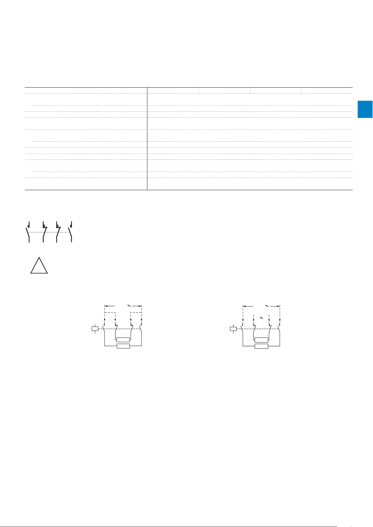
These contactors are suitable for controlling 2 separate circuits, i.e. 2 loads with 2 separate supplies, or 1 circuit comprising
2 separate loads with a single supply (see diagrams below). When the contactor operates there is no mechanical overlapping
between the N.O. poles and the N.C. poles: BREAK before MAKE.
These contactors are not suitable for a reversing starter or for controlling a single load from 2 separate supplies.
Block diagrams
– Single supply and 2 separate loads – 2 separate supplies and 2 separate loads
Supply
A1
R3
1
R4
2
A2
Load
Load
7
R5
8
R6
Main
supply
Back-up
supply
A1
R3
1
R4
2
A2
Load
Load
7
R5
8
R6
1SBC100111S0201 - Rev. A
ABB | 75
Page 3

AF09(Z)B..RT ... AF38(Z)B..RT 4-pole contactors
Pos. 2
-30°
Technical data
Magnet system characteristics
Contactor types
Coil operating limits
acc. to IEC 60947-4-1
2
DC control voltage
Rated control circuit voltage Uc
Coil consumption
PLC-output control
AC control voltage 50/60 Hz
Rated control circuit voltage Uc
Coil consumption
Max. permitted control voltage
during voltage fluctuation defined
acc. to IEC 60077 / EN 50155
Drop-out voltage
Operating time
Between coil energization and:
Between coil de-energization and:
DC supply
AC supply
Average pull-in value
Average holding value
Average pull-in value
Average holding value
N.O. contact closing
N.C. contact opening
N.O. contact opening
N.C. contact closing
AF09(Z)B..RT AF16( Z)B..R T AF26(Z)B..RT AF38(Z)B..RT
(AF..ZB) at θ ≤ 70 °C 0.85 x Uc min ... 1.1 x Uc max
(AF..B) at θ ≤ 60 °C 0.85 x Uc min ... 1.1 x Uc max; at θ ≤ 70 °C 0.85 x Uc min ... Uc max
at θ ≤ 60 °C 0.85 x Uc min ... 1.1 x Uc max
at θ ≤ 70 °C 0.85 x Uc min ... Uc max
20...250 V DC
(AF..Z) 12...16 W
(AF..Z) 1.7 W
(AF..Z) ≥ 500 mA 24 V DC
(AF..ZB) 24 ... 250 V AC - (AF..B) 250 ... 500 V AC
(AF..ZB) 16 VA - (AF..B) 50 VA
(AF..ZB) 1.7 VA / 1.5 W - (AF..B) 2.2 VA / 2 W
Rated control circuit voltage / Max. permitted control voltage
24 ... 60 V AC 50/60 Hz / 75 V AC 50/60 Hz
48 ... 130 V AC 50/60 Hz / 150 V AC 50/60 Hz
100 ... 250 V AC 50/60 Hz / 275 V AC 50/60 Hz
250 ... 500 V AC 50/60 Hz / 550 V AC 50/60 Hz
≤ 60 % of Uc min.
40...95 ms
38...90 ms
11...95 ms
13...98 ms
Mounting characteristics and conditions for use
Contactor types
Mounting positions
Mounting distances
Fixing
On rail according to IEC 60715, EN 60715
By screws (not supplied)
AF09(Z)B..RT AF16( Z)B..R T AF26(Z )B..RT AF38(Z)B..RT
Pos. 4
Max. add-on N.C. auxiliary contacts:
see accessory fitting details for a 4-pole contactor AF09(Z)B ... AF38(Z)B
The contactors can be assembled side by side
35 x 7.5 mm or 35 x 15 mm
2 x M4 screws placed diagonally
Pos. 1
Pos. 3
Pos. 1 - 30°
Pos. 5
78 | ABB
1SBC101852S0201 - Rev. A
Page 4

AF09(Z)B..RT ... AF38(Z)B..RT 4-pole contactors
E
max
L
E
L
Technical data
Connecting characteristics
Contactor types DC operated
Main terminals
Connection capacity (min. ... max.)
Main conductors (poles)
Flexible with insulated ferrule 1 or 2 x
P
Connection capacity acc. to UL/CSA 1 or 2 x
Tightening torque
Coil conductors
Flexible with insulated ferrule 1 or 2 x
max
P
Connection capacity acc. to UL/CSA 1 or 2 x
Tightening torque
Degree of protection
acc. to IEC 60947-1 / EN 60947-1 and IEC 60529 / EN 60529
All terminals
Front face
Screw terminals
Main terminals
Screwdriver type
Coil terminals
Ø mm >
L mm <
P mm <
E mm <
Ø mm >
L mm <
P mm <
E mm <
Screwdriver type
AF09(Z)B..RT AF16(Z) B..RT AF26(Z)B..RT AF38(Z)B..RT
Conductors with insulated ring tongue ferrule
0.75...6 mm²
3.5 mm
9.6 mm
5 mm
3.6 mm
AWG 16...10
1.2 Nm / 11 Ib.in
0.75...2.5 mm²
3.5 mm
8 mm
4.7 mm
2.9 mm
AWG 18...14
1.2 Nm / 11 Ib.in
IP10
IP20
Delivered in open position, screws of unused terminals must be tightened
M3.5
Flat Ø 5.5 / Pozidriv 2
M3.5
Flat Ø 5.5 / Pozidriv 2
1.5...16 mm²
9.3 mm
5.7 mm
AWG 16...6
1.2 Nm/11 lb.in
2
1SBC101813S0201 - Rev. A
ABB | 81
 Loading...