

Page 1

AF09 ... AF80 4-pole contactors
Technical data
Main pole - Utilization characteristics according to IEC
Contactor types
Standards IEC 60947-1 / 60947-4-1 and EN 60947-1 / 60947-4-1
Rated operational voltage Ue max. 690 V
Rated frequency (without derating) 50 / 60 Hz
Conventional free-air thermal current Ith
acc. to IEC 60947-4-1, open contactors, θ ≤ 40 °C
With conductor cross-sectional area 6 mm² 6 mm² 16 mm² 16 mm² 35 mm² 35 mm² 50 mm²
AC-1 Utilization category
For air temperature close to contactor
Ie / Rated operational current AC-1
Ue max. ≤ 690 V, 50/60 Hz
With conductor cross-sectional area 4 mm² 6 mm² 10 mm² 16 mm² 35 mm² 35 mm² 50 mm²
AC-3 Utilization category
For air temperature close to contactor θ ≤ 60°C
Ie / Max. rated operational current AC-3 (1)
5
M
3-phase motors
3
Rated operational power AC-3 (1)
M
3
Rated making capacity AC-3 10 x Ie AC-3 acc. to IEC 60947-4-1
Rated breaking capacity AC-3 8 x Ie AC-3 acc. to IEC 60947-4-1
Short-circuit protection device for contactors
Without thermal overload relay - Motor protection excluded
Ue ≤ 500 V AC - gG type fuse 25 A 32 A 50 A 63 A 80 A 110 A 160 A
Rated short-time withstand current Icw
At 40 °C ambient temperature,
in free air from a cold state
Maximum breaking capacity
cos φ = 0.45
Power dissipation per pole
Max. electrical switching frequency
(1) For the corresponding kW/A values of 1500 r.p.m, 50 Hz or 1800 r.p.m, 60 Hz, 3-phase motors, see "Motor Rated Operational Powers and Currents"
(2) For the protection of motor starters against short circuits, see "Coordination with Short-circuit Protection Devices".
(3) 400 V 3-phase motors only.
1500 r.p.m. 50Hz
1800 r.p.m. 60Hz
3-phase motors
N.O. main pole
N.C. Main pole
AC / DC operated
θ ≤ 40 °C
θ ≤ 60 °C
θ ≤ 70 °C
220-230-240V
380-400V
415V
440V
500V
690V
220-230-240V
380-400V
415V
440V
500V
690V
1 s
10 s
30 s
1 min
15 min
at 440 V
at 690 V
at 440 V
at 690 V
Ie / AC-1
Ie / AC-3
AC-1
AF09 AF16 AF26 AF38 AF40 AF52 AF80
35 A 35 A 55 A 55 A 105 A 105 A 125 A
25 A 30 A 45 A 55 A 70 A 100 A 125 A
25 A 30 A 40 A 45 A 60 A 80 A 105 A
22 A 26 A 32 A 37 A 50 A 70 A 90 A
9 A 18 A 23.2 A 23.2 A 40 A 53 A 80 A
9 A 18 A 22 A 22 A 40 A 53 A 80 A
9 A 18 A 21.2 A 21.2 A 40 A 53 A 80 A
9 A 18 A 20 A 20 A 40 A 53 A 80 A
9.5 A 15 A 17.6 A 17.6 A 35 A 45 A 65 A
7 A 10.5 A 10.5 A 10.5 A 25 A 35 A 49 A
2.2 kW 4 kW 5.5 kW 5.5 kW 11 kW 15 kW 22 kW
4 kW 7.5 kW 11 kW (3) 11 kW (3) 18.5 kW 22 kW 37 kW
4 kW 9 kW 11 kW 11 kW 22 kW 30 kW 45 kW
4 kW 9 kW 11 kW 11 kW 22 kW 30 kW 45 kW
5.5 kW 9 kW 11 kW 11 kW 22 kW 30 kW 45 kW
5.5 kW 9 kW 9 kW 9 kW 22 kW 30 kW 45 kW
300 A 300 A 450 A 450 A 1000 A 1000 A 1200 A
150 A 150 A 300 A 300 A 600 A 600 A 780 A
80 A 80 A 225 A 225 A 350 A 350 A 450 A
60 A 60 A 150 A 150 A 250 A 250 A 300 A
35 A 35 A 55 A 55 A 110 A 110 A 140 A
250 A 250 A - - 950 A 950 A 1100 A
106 A 106 A - - 600 A 600 A 750 A
----600 A - 900 A
----300 A - 750 A
0.8 W 1.2 W 1.6 W 2.3 W 3 W 6.3 W 8 W
0.1 W 0.35 W 0.42 W 0.42 W 1 W 1.7 W 3.2 W
600 cycles/h
5/220 | ABB
1SBC101989S0201 - Rev. B
Page 2

AF09 ... AF80 4-pole contactors
Technical data
Main pole - Utilization characteristics according to UL/NEMA/CSA
Contactor types
Standards UL 508, CSA C22.2 N°14 UL 60947-4-1, CSA-C22.2 No. 60947-4-1
Max. operational voltage 600 V
UL / CSA general use rating
With conductor cross-sectional area
1 pole
2 poles in serie
3 poles in serie
4 poles in serie
With conductor cross-sectional area AWG 10 AWG 10 AWG 8 AWG 8 AWG 6 AWG 4 AWG 2
Max. electrical switching frequency
For general use 600 cycles/h
Note: 4-pole contactors fitted with 2 N.O. + 2 N.C. main poles, see "General technical data".
(1) 20 A for AF09..-22-00 and AF16..-22-00.
5
AC / DC operated
600 V AC
80 V DC
160 V DC
240 V DC
320 V DC
AF09 AF16 AF26 AF38 AF40 AF52 AF80
25 A 30 A 45 A 55 A 60 A 80 A 105 A
AWG 10 AWG 10 AWG 8 AWG 6 AWG 6 AWG 4 AWG 2
25 A (1) 30 A (1) 45 A 55 A 60 A 80 A 105 A
25 A (1) 30 A (1) 45 A 55 A 60 A 80 A 105 A
25 A 30 A 45 A 55 A 60 A 80 A 105 A
25 A 30 A 45 A 55 A 60 A 80 A 105 A
Main pole utilization characteristics - 4 N.O. non-reversing contactors
Contactor types
Lighting application - UL / CSA - breaking all lines
Electrical discharge lamps (ballast)
1-phase per pole
3-phase break all lines
Elevator control, load switching, 500 000 electrical operating cycles
acc. to CSA B44.1 / ASME 17.5 paragraph 19.2.1
1-phase
Horse power rating
3-phase
Horse power rating
Note: 4-pole contactors fitted with 2 N.O. + 2 N.C. main poles, see "General technical data".
AC / DC operated
347 V AC
600 V AC
110-120 V AC
220-240 V AC
200-208 V AC
220-240 V AC
440-480 V AC
550-600 V AC
AF09 AF16 AF26 AF38 AF40 AF52 AF80
20 A 30 A 45 A 50 A - - 20 A 30 A 45 A 50 A - - -
- 1/2 hp - - - - -
- 1-1/2 hp - - - - -
-3 hp-----
-3 hp-----
- 7-1/2 hp - - - - -
- 10 hp - - - - -
5/222 | ABB
1SBC100066S0201
Page 3
AF09 ... AF80 4-pole contactors
Technical data
General technical data
Contactor types
Rated insulation voltage Ui
acc. to IEC 60947-4-1 690 V 1000 V
acc. to UL / CSA 600 V
Rated impulse withstand voltage Uimp. 6 kV 8 kV
Electromagnetic compatibility Devices complying with IEC 60947-1 / EN 60947-1 - Environment A and B (1)
Ambient air temperature close to contactor
Operation -40...+70 °C
Storage -60...+80 °C
Climatic withstand Category B according to IEC 60947-1 Annex Q
Maximum operating altitude (without derating) 3000 m
Mechanical durability
Number of operating cycles 10 millions operating cycles
Max. switching frequency 3600 cycles/h
Shock withstand
acc. to IEC 60068-2-27 and EN 60068-2-27
5
Mounting position 1
4 N.O.
Main poles
C1
A
B1
A
B2
2 N.O. + 2 N.C.
Main poles
C2
Vibration withstand
acc. to IEC 60068-2-6
(1) Environment B: all AF09 … AF38 contactors produced since week 08-2013. AF09 … AF38-..-..-12 (48...130 V 50/60 Hz-DC) compliant to environment A only.
For environment B: select AF09 … AF38-..-..-22.
AC / DC operated
Shock direction
A
B1
B2
C1
C2
A
B1
B2
C1
C2
AF09 AF16 AF26 AF38 AF40 AF52 AF80
1/2 sinusoidal shock for 11 ms: no change in contact position, closed or open position
30 g 20 g
25 g closed position / 5 g open position 20 g closed position / 5 g open position
15 g 10 g
25 g 20 g
25 g 20 g
30 g closed position / 25 g open position 20 g
25 g closed position / 5 g open position 20 g closed position / 4 g open position
15 g closed position / 10 g open position 10 g
25 g closed position / 20 g open position 20 g
25 g closed position / 20 g open position 20 g
5...300 Hz
4 g closed position / 2 g open position
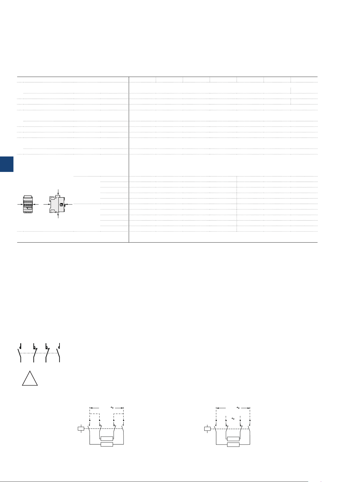
Remark for 4-pole contactors fitted with 2 N.O. + 2 N.C. main poles
7
R5
R3
1
These contactors are suitable for controlling 2 separate circuits, i.e. 2 loads with 2 separate supplies, or 1 circuit comprising
2 separate loads with a single supply (see diagrams below). When the contactor operates there is no mechanical overlapping
between the N.O. poles and the N.C. poles: BREAK before MAKE.
8
R6
R4
!
These contactors are not suitable for a reversing starter or for controlling a single load from 2 separate supplies.
Block diagrams
– Single supply and 2 separate loads – 2 separate supplies and 2 separate loads
Supply
5/224 | ABB
A1
R3
1
R4
2
A2
Load
Load
7
R5
8
R6
A1
A2
Main
supply
Back-up
supply
7
R5
R3
1
8
R6
R4
2
Load
Load
1SBC 101990S 0201
Page 4
AF09 ... AF80 4-pole contactors
Technical data
Magnet system characteristics
Contactor types
Coil operating limits
acc. to IEC 60947-4-1
AC control voltage 50/60 Hz
Rated control circuit voltage Uc 24...500 V AC
Coil consumption
DC control voltage
Rated control circuit voltage Uc 12...500 V DC 20...500 V DC
Coil consumption
PLC-output control (AF..Z) ≥ 500 mA 24 V DC -
5
Drop-out voltage ≤ 60 % of Uc min. ≤ 60 % of Uc min.
Voltage sag immunity
acc. to SEMI F47-0706 (AF..Z) conditions of use on request conditions of use on request
Dips withstand
-20 °C ≤ θ ≤ +60°C
Operating time
Between coil energization and:
Between coil de-energization and:
AC / DC operated
AC supply
DC supply
Average pull-in value
Average holding value
Average pull-in value
Average holding value
N.O. contact closing
N.C. contact opening
N.O. contact opening
N.C. contact closing
AF09 AF16 AF26 AF38 AF40 AF52 AF80
At θ ≤ 60 °C 0.85 x Uc min...1.1 x Uc max.
At θ ≤ 70 °C 0.85 x Uc min...Uc max.
At θ ≤ 60 °C 0.85 x Uc min...1.1 x Uc max.
At θ ≤ 70 °C (AF) 0.85 x Uc min...Uc max. - (AF..Z) 0.85 x
Uc min...1.1 x Uc max.
(AF) 50 VA - (AF..Z) 16 VA 40 VA
(AF) 2.2 VA / 2 W - (AF..Z) 1.7 VA / 1.5 W 4 VA / 2 W
(AF) 50 W - (AF..Z) 12...16 W 40 W
(AF) 2 W - (AF..Z) 1.7 W 2 W
(AF..Z) 22 ms average for Uc ≥ 24 V 50/60 Hz or
Uc ≥ 20 V DC
40...95 ms 48...120 ms
38...90 ms 44...115 ms
11...95 ms 16...110 ms
13...98 ms 18...113 ms
at θ ≤ 70 °C 0.85 x Uc min ... 1.1 x Uc max
at θ ≤ 70 °C 0.85 x Uc min ... 1.1 x Uc max
24 ms average
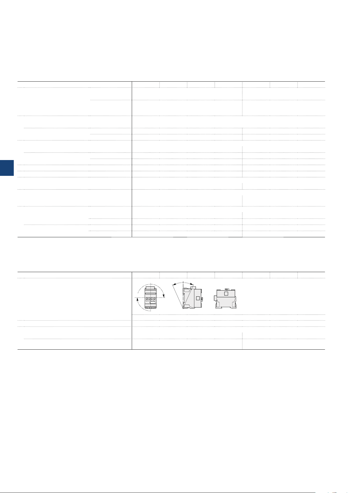
Mounting characteristics and conditions for use
Contactor types
Mounting positions
Mounting distances The contactors can be assembled side by side
Fixing
On rail according to IEC 60715, EN 60715 35 x 7.5 mm or 35 x 15 mm 35 x 15 mm
By screws (not supplied) 2 x M4 screws placed diagonally 2 x M4 or 2 x M6 screws
AF09 AF16 AF26 AF38 AF40 AF52 AF80
. 2
Pos
Pos. 4
Pos. 1 Pos. 1 ± 30°
Max. add-on N.C. auxiliary contacts: see accessory fitting details for a 4-pole contactor AF09 ... AF80
+30° -30°
Pos. 3
Pos. 5
placed diagonally
5/226 | ABB
1SBC 101991S02 01
Page 5

AF09 ... AF80 4-pole contactors
Technical data
Connecting characteristics
Contactor types
Main terminals
AF09 AF16 AF26 AF38 AF40 AF52 AF80
Screw terminals with
cable clamp
Connection capacity (min. ... max.)
Main conductors (poles)
Rigid Solid (≤ 4 mm²)
Stranded (≥ 6 mm²)
Flexible with non insulated ferrule
Flexible with insulated ferrule
Bars or lugs
L
6
Connection capacity acc. to UL/CSA
Stripping length 10 mm 12 mm 16 mm 17 mm
Tightening torque 1.5 Nm / 13 lb.in 2.5 Nm / 22 lb.in 4 Nm / 35 lb.in 6 Nm / 53 lb.in
Auxiliary conductors
(coil terminals)
Rigid solid
Flexible with non insulated ferrule
Flexible with insulated ferrule
Lugs
L
6
Connection capacity acc. to UL/CSA
Stripping length 10 mm
Tightening torque 1.2 Nm / 11 lb.in
Degree of protection
acc. to IEC 60947-1 / EN 60947-1 and IEC 60529 / EN 60529
Main terminals IP20 IP10
Coil terminals IP20
Screw terminals Delivered in open position, screws of unused terminals must be tightened
Main terminals M3.5 M4.5 M6 M8
Coil terminals M3.5
Screwdriver type
Screwdriver type
1 x
1...6 mm² 1.5...16 mm² 6...35 mm² 6...70 mm²
2 x
1...6 mm² 1.5...16 mm² 6...35 mm² 6...50 mm²
1 x
0.75...6 mm² 1.5...16 mm² 4...35 mm² 6...50 mm²
2 x
0.75...6 mm² 1.5...16 mm² 4...35 mm² 6...50 mm²
1 x
0.75...4 mm² 1.5...16 mm² 4...35 mm² 6...50 mm²
2 x
0.75...2.5 mm² 1.5...16 mm² 4...35 mm² 6...50 mm²
L <
9.6 mm - 9.2 mm 12.2 mm
1 or 2 x
AWG 16...10 AWG 16...6 AWG 10...2 AWG 6...1
1 x
1...2.5 mm²
2 x
1...2.5 mm²
1 x
0.75...2.5 mm²
2 x
0.75...2.5 mm²
1 x
0.75...2.5 mm²
2 x
0.75...1.5 mm²
L <
8 mm
1 or 2 x
AWG 18...14
Flat Ø 5.5 / Pozidriv 2 Flat Ø 6.5 / Pozidriv 2 hexagon socket (s = 4 mm)
Flat Ø 5.5 / Pozidriv 2
Screw terminals with
double connector
2 x (5.5 width x 6.8
depth)
Screw terminals with
double connector
2 x (9.3 width x 7.9/10.3
depth)
Screw terminals with
double connector
2 x (12.4 width x 9.3/11.1
depth)
5
ABB | 5/229
1SBC101988S0201 - Rev. A
 Loading...