

Page 1
ACH550
User’s Manual
ACH550-UH HVAC Drives (1
ACH550-BCR/BDR/VCR/VDR E-Clipse Bypass Drives (1
…550 HP)
…400 HP)
ACH550-PCR/PDR Packaged Drives with Disconnect (1
…550 HP)
Page 2

List of related manuals
GENERAL MANUALS
ACH550-UH HVAC Drives User’s Manual (1...550 HP)
3AUA0000004092 (English)
• Safety
•Installation
• Control panel
• Start-up
• Application macros
• Parameters
• Embedded fieldbus
• Fieldbus adapter
• Diagnostics
• Maintenance
• Technical data
ACH550-BCR/BDR/VCR/VDR E-Clipse Bypass Drives
User’s Manual (1...400 HP)
3AUA0000016461 (English)
• Safety
•Installation
• Control panel
• Start-up
• Bypass functions overview
• Application macros
• Parameters
• Embedded fieldbus
• Fieldbus adapter
• Diagnostics
• Technical data
ACH550-PCR/PDR Packaged Drives with Disconnect
User’s Manual (1...550 HP)
3AUA0000031590 (English)
• Safety
•Installation
• Maintenance
• Technical data
OPTION MANUALS
(delivered with optional equipment)
MFDT-01 FlashDrop User’s Manual
3AFE68591074 (English)
OHDI-01 115/230 V Digital Input Module User’s Manual
3AUA0000003101 (English)
OREL-01 Relay Output Extension Module User’s
Manual
3AUA0000001935 (English)
RCNA-01 ControlNet Adapter User’s Manual
3AFE64506005 (English)
RDNA-01 DeviceNet Adapter User’s Manual
3AFE64504223 (English)
RETA-01 Ethernet Adapter Module User’s Manual
3AFE64539736 (English)
RETA-02 Ethernet Adapter Module User’s Manual
3AFE68895383 (English)
RLON-01 LONWORKS® Adapter Module User’s
Manual
3AFE64798693 (English)
RPBA-01 PROFIBUS DP Adapter Module User’s
Manual
3AFE64504215 (English)
SREA-01 Ethernet Adapter User’s Manual
3AUA0000042896 (English)
Typical contents
• Safety
• Installation
• Programming/Start-up
• Diagnostics
• Technical data
MAINTENANCE MANUALS
Guide for Capacitor Reforming in ACS50, ACS55,
ACS150, ACS310, ACS320, ACS350, ACS550 and
ACH550
3AFE68735190 (English)
APOGEE is a registered trademark of Siemens Building
Technologies Inc.
BACnet is a registered trademark of ASHRAE.
ControlNet™ is a trademark of ODVA™.
DeviceNet™ is a trademark of ODVA™.
DRIVECOM is a registered trademark of DRIVECOM User
Group e.V.
EtherNet/IP™ is a trademark of ODVA™.
Interbus is a registered trademark of Interbus Club.
ONWORKS® is a registered trademark of Echelon
L
Corporation.
Metasys is a registered trademark of Johnson Controls Inc.
Modbus and Modbus/TCP are registered trademarks of
Schneider Automation Inc.
PROFIBUS, PROFIBUS DP and PROFINET IO are
registered trademarks of Profibus International.
Page 3

ACH550-PCR/PDR User’s Manual 3-1
ACH550-PCR/PDR Packaged Drives
with Disconnect
1…550 HP
User’s Manual
2012 ABB. All Rights Reserved.
Page 4

Page 5
ACH550-PCR/PDR User’s Manual 3-3
Safety
Use of warnings and notes
There are two types of safety instructions throughout this manual:
• Notes draw attention to a particular condition or fact, or give information on a
subject.
• Warnings caution you about conditions which can result in serious injury or death
and/or damage to the equipment. They also tell you how to avoid the danger. The
warning symbols are used as follows:
Electricity warning warns of hazards from electricity which can cause physical
injury and/or damage to the equipment.
General warning warns about conditions, other than those caused by electricity,
which can result in physical injury and/or damage to the equipment.
WARNING! The ACH550 adjustable speed AC drive should ONLY be installed by a
qualified electrician.
WARNING! Even when the motor is stopped, dangerous voltage is present at the
power circuit terminals U1, V1, W1 (L1, L2, L3) and U2, V2, W2 (T1, T2 T3) and,
depending on the frame size, UDC+ and UDC-, or BRK+ and BRK-.
WARNING! Dangerous voltage is present when input power is connected. After
disconnecting the supply, wait at least 5 minutes (to let the intermediate circuit
capacitors discharge) before removing the cover.
WARNING! Even when power is switched off from the input terminals of the
ACH550, there may be dangerous voltage (from external sources) on the terminals
of the relay outputs.
WARNING! When the control terminals of two or more drives are connected in
parallel, the auxiliary voltage for these control connections must be taken from a
single source which can either be one of the drives or an external supply.
Safety
Page 6
3-4 ACH550-PCR/PDR User’s Manual
WARNING! Disconnect the internal EMC filter when installing the drive on an IT
system (an ungrounded power system or a high-resistance-grounded [over 30 ohm]
power system).
WARNING! Do not attempt to install or remove EM1, EM3, F1 or F2 screws while
power is applied to the drive’s input terminals.
WARNING! Do not control the motor with the disconnecting device (disconnecting
means); instead, use the control panel keys or commands via the I/O board of the
drive. The maximum allowed number of charging cycles of the DC capacitors (i.e.
power-ups by applying power) is five in ten minutes.
WARNING! Never attempt to repair a malfunctioning ACH550; contact the factory or
your local Authorized Service Center for repair or replacement.
WARNING! The ACH550 will start up automatically after an input voltage
interruption if the external run command is on.
WARNING! The heat sink may reach a high temperature.
Note: For more technical information, contact the factory or your local ABB
representative.
Safety
Page 7

ACH550-UH User’s Manual 3-5
Table of contents
Safety
Use of warnings and notes . . . . . . . . . . . . . . . . . . . . . . . . . . . . . . . . . . . . . . . 3-3
Table of contents
Installation
Application . . . . . . . . . . . . . . . . . . . . . . . . . . . . . . . . . . . . . . . . . . . . . . . . . . . 3-7
Input disconnect features and functions . . . . . . . . . . . . . . . . . . . . . . . . . . . . . 3-7
Installation flow chart . . . . . . . . . . . . . . . . . . . . . . . . . . . . . . . . . . . . . . . . . . . 3-9
Preparing for installation (supplement to ACH550-UH User’s Manual) . . . . 3-10
Installing the wiring (supplement to ACH550-UH User’s Manual) . . . . . . . . 3-11
Maintenance
Maintenance intervals . . . . . . . . . . . . . . . . . . . . . . . . . . . . . . . . . . . . . . . . . 3-17
Enclosure air filter replacement –
UL Type / NEMA 12 hinged door wall mount enclosures . . . . . . . . . . . . . . . 3-18
Enclosure air filter replacement –
UL Type / NEMA 12 floor mount enclosures . . . . . . . . . . . . . . . . . . . . . . . . 3-18
Technical data
Input power connections (supplement to ACH550-UH User’s Manual) . . . . 3-19
Dimensional references . . . . . . . . . . . . . . . . . . . . . . . . . . . . . . . . . . . . . . . . 3-25
Dimensions and weights (supplement to ACH550-UH User’s Manual) . . . . 3-28
Degrees of protection . . . . . . . . . . . . . . . . . . . . . . . . . . . . . . . . . . . . . . . . . . 3-31
Applicable standards . . . . . . . . . . . . . . . . . . . . . . . . . . . . . . . . . . . . . . . . . . 3-32
Index
Table of contents
Page 8

3-6 ACH550-UH User’s Manual
Table of contents
Page 9
ACH550-PCR/PDR User’s Manual 3-7
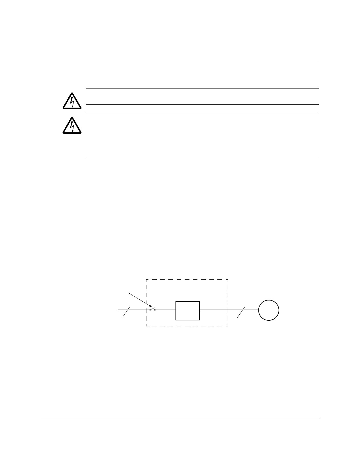
ACH550
Drive with Input Disconnect
Motor
3 Phase
Drive
3
3
Disconnect Switch
or Circuit Breaker
Input Power
Installation
Study these installation instructions carefully before proceeding. Failure to observe
the warnings and instructions may cause a malfunction or personal hazard.
WARNING! Before you begin read Safety on page 3-3.
WARNING! When the ACH550 with Input Disconnect is connected to the line power,
the Motor Terminals T1, T2, and T3 are live even if the motor is not running. Do not
make any connections when the ACH550 with Input Disconnect is connected to the
line. Disconnect and lock out power to the drive before servicing the drive. Failure to
disconnect power may cause serious injury or death.
Application
This manual contains supplemental information that is unique to ACH550 input
disconnect configurations (PCR or PDR). Refer to the base manual, ACH550-UH
HVAC User’s Manual (1…550 HP) on page 1-1, for all other information.
Input disconnect features and functions
The ACH550 with Input Disconnect is an ACH550 AC adjustable frequency drive
packaged with an input disconnect switch or circuit breaker, and with a door
mounted, external operating handle. The operating handle can be padlocked in the
OFF position (padlock not supplied). Enclosure options are UL Type 1, UL Type 12,
and UL Type 3R (NEMA 1, NEMA 12, and NEMA 3R).
The following is a typical power diagram.
Installation
Page 10
3-8 ACH550-PCR/PDR User’s Manual
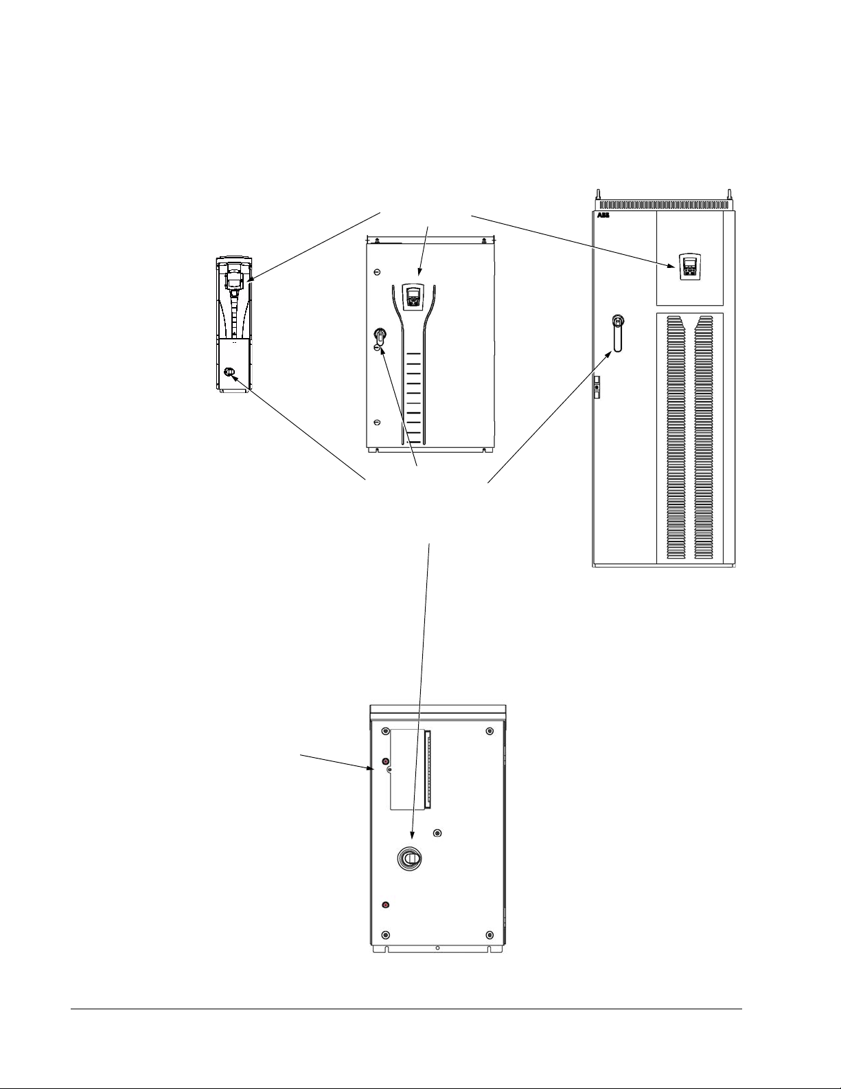
Operating Handle
ACH550 Drive
for Disconnect Switch
or Circuit Breaker
UL Type / NEMA 1 & 12 UL Type / NEMA 1 & 12 UL Type / NEMA 1 & 12
Floor Mount
UL Type / NEMA 3R
Enclosures
Control Panel
Vertical Construction
Enclosures
Hinged Door Wall Mount
Enclosures
Enclosures
ACH550 Drive
Control Panel with
Hinged Cover
The following shows the front view of the ACH550 Drive with Input Disconnect
standard configurations, and identifies the major components.
Installation
Page 11
ACH550-PCR/PDR User’s Manual 3-9
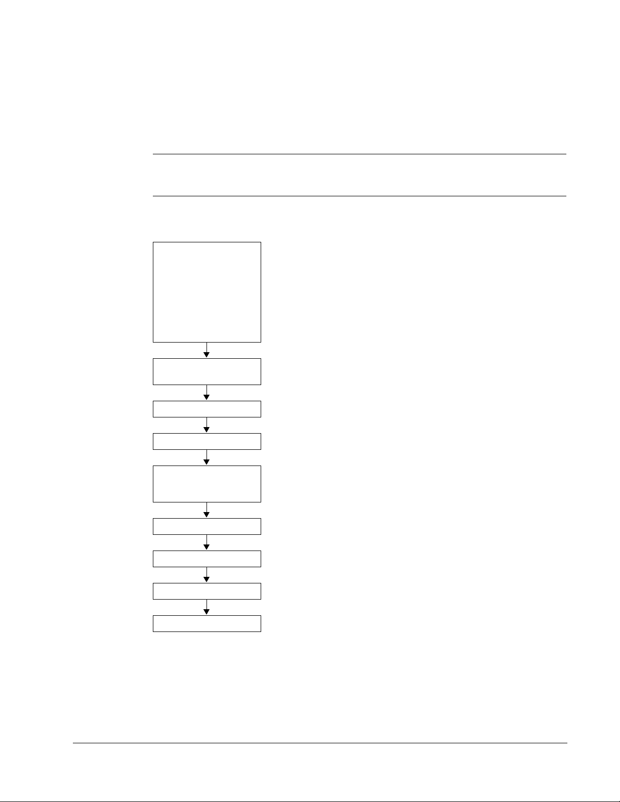
Installation flow chart
The installation of Input Disconnect configurations for ACH550 drives follows the
outline below. The steps must be carried out in the order shown. At the right of each
step are references to the detailed information needed for the correct installation of
the unit.
Note: References in the middle column below are to the ACH550-UH User’s
Manual. References in the third column below are to this manual.
Refer to the ACH550-UH
Task
PREPARE for
installation
PREPARE the mounting
location
REMOVE the front cover Remove front cover --
MOUNT the drive Mount the drive --
INSTALL wiring Wiring overview and
User’s Manual Installation
section
Preparing for installation •Drive identification on page 3-10.
Prepare the mounting
location
Install the wiring
Additional Reference in this
Manual
• Note: Some instructions in this
document vary, depending on
the drive’s frame size. To read
the Ratings table, you need the
“Output current rating” entry from
the Type code (see page 3-10).
Also see Suitable mounting
location on page 3-11.
--
Installing the wiring (supplement to
ACH550-UH User’s Manual) on
page 3-11.
CHECK installation Check installation --
RE-INSTALL the cover Re-install cover --
APPLY power Apply power --
START-UP Start-up --
Installation
Page 12

3-10 ACH550-PCR/PDR User’s Manual
Preparing for installation (supplement to ACH550-UH User’s Manual)
Drive identification
Drive label
To identify the type of device you are installing, refer to the type code number on the device
identification label.
• Wall mounting base drives – label attached on the side surface of the heat sink.
• Packaged drive with screw cover – label attached to outside surface on the left side of enclosure.
• Enclosure with hinged cover/door – label on inside surface of the cover/door.
Type code
Use the following to interpret the type code found on the identification label.
ACH550-UH-015A-4 +…+…
AC, HVAC Drive = 550 Product Series
Construction
UH = Base Drive
BCR = E-Clipse Bypass with circuit breaker
BDR = E-Clipse Bypass with disconnect switch
CC = Classic Bypass with circuit breaker
CD = Classic Bypass with disconnect switch
PCR = Drive with circuit breaker
PDR = Drive with disconnect switch
VCR = Vertical bypass with circuit breaker
VDR = Vertical bypass with disconnect switch
Output current rating (See ratings chart for details)
Vol tage rati ng
2 = 208…240 VAC
4 = 380…480 VAC
6 = 500…600 VAC
Enclosure protection class
No specification = UL Type 1/NEMA 1
+B055 = UL Type 12/NEMA 12
+B058 = UL Type 3R/NEMA 3R
Power options
+E213 = Line reactor
+F267 = Service switch
Input/Output option modules
+L511 = Relay output extension
+L512 = 115/230 V digital input interface
Fieldbus adaptors
+K451 = DeviceNet Adapter
+K452 = LonWorks Adapter
+K454 = Profibus Adapter
+K462 = ControlNet Adapter
+K466 = Ethernet Adapter
Installation
Page 13

ACH550-PCR/PDR User’s Manual 3-11
Ratings and frame size
The charts in the Ratings section on page 1-297 of the ACH550-UH User’s Manual
manual list technical specifications, and identify the drive’s frame size.
Note: Some instructions in this document vary, depending on the drive’s frame size.
To read the Ratings table, you need the “Output current rating” entry from the Type
code (see page 3-10).
Suitable mounting location
For selecting a suitable mounting location for PCR/PDR configurations, refer to:
• The ACH550-UH User’s Manual on page 1-13, and
• The Technical data section on page 3-19 in this manual for the appropriate
information on dimensions and weights
• UL Type 3R, PX3R-1...PX3R-4 enclosures are designed to be mounted on a wall.
Mounting these 3R enclosures on an open rack system requires the use of the
supplied 3R enclosure back plates to maintain 3R integrity.
Installing the wiring (supplement to ACH550-UH User’s Manual)
WARNING!
• Metal shavings or debris in the enclosure can damage electrical equipment and
create a hazardous condition. Where parts, such as conduit plates require cutting
or drilling, first remove the part. If that is not practical, cover nearby electrical
components to protect them from all shavings or debris.
• Do not connect or disconnect input or output power wiring, or control wires, when
power is applied.
• Never connect line voltage to drive output Terminals T1, T2, and T3.
• Do not make any voltage tolerance tests (Hi Pot or Megger) on any part of the
unit. Disconnect motor wires before taking any measurements in the motor or
motor wires.
• Make sure that power factor correction capacitors are not connected between the
drive and the motor.
Wiring requirements
Refer to the Wiring requirements section on page 1-18 in the ACH550-UH User’s
Manual. The requirements apply to all ACH550 drives. In particular:
• Use separate, metal conduit runs for the following different classes of wiring:
– Input power wiring.
– Motor wiring.
– Control/communications wiring.
• Properly and individually ground the drive, the motor and cable shields.
Installation
Page 14

3-12 ACH550-PCR/PDR User’s Manual
ACH550
Input Power
Terminals
Motor
Terminals
Ground
Lug(s)
Disconnect Switch
or Circuit Breaker
Motor
Terminals
Gnd
UL Type / NEMA 1 & 12 UL Type / NEMA 1 & 12
Enclosures Enclosures
Input Power
Terminals
I/O Conduit
(Bottom)
I/O Conduit
(Top)
Vertical Construction Hinged Door Wall Mount
I/O Conduit
(Bottom)
Input Power
Terminals
Disconnect Switch
or Circuit Breaker
UL Type / NEMA 3R
Enclosures
ACH550
Motor
Te rm i na l s
Ground
Lug
RHTR Temperature
HI / LO Jumper (X1)
Heater ON
Temperature
Heater OFF
Temperature
Default Setting
(X1 jumper in LO position)
14.4 °C
58 °F
21.4 °C
70.5 °F
Alternate Setting
(X1 jumper in HI position)
17.8 °C
64 °F
24.7 °C
76.5 °C
The alternate (HI) setting further reduces the likelihood
of condensate in high humidity environments.
Wiring overview
Connection diagrams – standard drive with input disconnect (wall mounted)
The following figure shows the Standard Drive with Input Disconnect (wall mounted)
wiring connection points. Refer to the ACH550-UH User’s Manual page 1-315 for
control connections to the drive.
Installation
Page 15

ACH550-PCR/PDR User’s Manual 3-13
ACH550
Input Power
Te rm i na l s
Motor
Terminals
Ground Lug
Bar
Disconnect Switch
or Circuit Breaker
Connection diagrams – standard drive with input disconnect (floor mounted)
Floor mounted UL Type / NEMA 1 & 12 Drive with Input Disconnect units are
configured for wiring access from the top and include a removable conduit mounting
plate. The following figure shows the wiring connection points. Refer to the
ACH550-UH User’s Manual page 1-315 for control connections to the drive.
Installation
Page 16

3-14 ACH550-PCR/PDR User’s Manual
Input
Power
Input
Power
UL Type / NEMA 1 & 12 UL Type / NEMA 1 & 12
Enclosures Enclosures
UL Type / NEMA 1 & 12
Enclosures
Dashed line is ground run.
Vertical Construction Hinged Door Wall Mount
Floor Mount
ACH550
Input Power
Terminals
Motor
Terminals
Ground Lug
Bar
Disconnect Switch
or Circuit Breaker
Install the line input wiring
Line input connections – standard drive with input disconnect configurations
Connect input power to the terminals of the disconnect switch or circuit breaker.
Connect the equipment grounding conductor to the ground lug at the top of the
enclosure. The figure below shows the connection points for Standard Drive with
Input Disconnect configurations.
Note: The terminals on disconnect switches for the following rated ACH550-PDR
products is 7 in-lbs. Do not use a power driver or over tighten to prevent breaking
Installation
screw heads or stripping the terminal.
-04A6-2 -03A3-4 -02A7-6
-06A6-2 -04A1-4 -03A9-6
-07A5-2 -06A9-4 -06A1-6
-012A-2 -08A8-4 -09A0-6
-017A-2 -012A-4 -011A-6
-024A-2 -015A-4 -017A-6
-031A-2 -023A-4
230 VAC 460 VAC 600 VAC
Page 17

ACH550-PCR/PDR User’s Manual 3-15
Input
Power
UL Type / NEMA 3R
Enclosures
RHTR Temperature
HI / LO Jumper (X1)
Heater ON
Temperature
Heater OFF
Temperature
Default Setting
(X1 jumper in LO position)
14.4 °C
58 °F
21.4 °C
70.5 °F
Alternate Setting
(X1 jumper in HI position)
17.8 °C
64 °F
24.7 °C
76.5 °C
The alternate (HI) setting further reduces the likelihood
of condensate in high humidity environments.
WARNING! Check the motor and motor wiring insulation before connecting the
ACH550 to line power. Follow the procedure in the ACH550-UH User’s Manual on
page 1-23. Before proceeding with the insulation resistance measurements, check
that the ACH550 is disconnected from incoming line power. Failure to disconnect
line power could result in death or serious injury.
Note: For the remainder of the wiring (motor and control wiring) refer to the
ACH550-UH User’s Manual.
Installation
Page 18

3-16 ACH550-PCR/PDR User’s Manual
Installation
Page 19

ACH550-PCR/PDR User’s Manual 3-17
Maintenance
Maintenance intervals
If installed in an appropriate environment, the drive requires very little maintenance.
This table lists the routine maintenance intervals recommended by ABB.
Maintenance Configuration Interval Instruction
Check/replace hinged
door wall mount
enclosure inlet air filter
Check/replace floor
mount enclosure inlet
air filter
Check/replace NEMA
3R enclosure air filters
Check/replace floor
mount enclosure
exhaust air filter.
Check and clean
heatsink.
Replace drive module
fan.
Replace enclosure
fan(s).
Change capacitor. Frame sizes R5
Replace battery in the
Assist
ant control
panel.
Hinged door wall
mount UL Type /
NEMA 12
enclosures
Floor mount UL
Type / NEMA 12
enclosures
UL Type / NEMA
3R enclosures PX3R-5 and
higher
Floor mount UL
Type / NEMA 12
enclosures
All Depends on the
All Every six years See Maintenance in ACH550-UH
UL Type / NEMA
12 and 3R
enclosures
and R6
All Every ten years See Maintenance in ACH550-UH
Check every 3
months. Replace
as needed.
Check every 3
months. Replace
as needed.
Check every 3
months. Replace
as needed.
Check every 6
months. Replace
as needed.
dustiness of the
environment
(every 6…12
months)
Every three years See Maintenance in ACH550-UH
Every ten years See Maintenance in ACH550-UH
Enclosure air filter replacement –
UL Type / NEMA 12 hinged door
wall mount enclosures on
page 3-18.
See Maintenance in ACH550-UH
User’s Manual and Enclosure air
filter replacement – UL Type /
NEMA 12 hinged door wall mount
enclosures on page 3-18.
See PX3R dimensional information
on page 3-30.
See Maintenance in ACH550-UH
User’s Manual and Enclosure air
filter replacement – UL Type /
NEMA 12 hinged door wall mount
enclosures on page 3-18.
See Maintenance in ACH550-UH
User’s Manual on page 1-289.
User’s Manual on page 1-290.
User’s Manual on page 1-291.
User’s Manual on page 1-296.
User’s Manual on page 1-296.
Maintenance
Page 20

3-18 ACH550-PCR/PDR User’s Manual
Enclosure
Mounting
Screw
Hook
Filter Bracket
Slot
Back of Enclosure
Enclosure air filter replacement – UL Type / NEMA 12 hinged door wall
mount enclosures
This procedure applies to drive with disconnect configurations in UL Type / NEMA 12
hinged door wall mount enclosures. This filter is located at the bottom of the
enclosure. Use the following procedure to check and replace filters.
1. On the enclosure, remove the screw holding the filter bracket in place.
2. Slide the filter bracket forward until the hooks on the bracket clear the slots on the
enclosure base. This step allows the filter and bracket to drop free from the
enclosure.
Enclosure air filter replacement – UL Type / NEMA 12 floor mount
enclosures
3. Lift the filter out of the filter bracket and replace as appropriate.
4. With the filter in the filter bracket, align the hooks on the bracket with the slots in the
enclosure base, and press the hooks up into the slots.
5. Slide the filter bracket back, making sure that the hooks catch on the enclosure.
6. Replace the mounting screw. Tighten until the gasket on the bracket is about 50%
compressed.
Filter material
Enclosure Type Inlet (door) Outlet (roof)
UL Type / NEMA 12 3AUA0000006723 (qty 1) 3AUA0000006722 (qty 2)
Note: When installing the filter media, the white side must face the outside of the
cabinet and the colored side must face the inside of the cabinet. Refer to the
ACH550-UH User’s Manual on page 1-293 for installation instructions.
Maintenance
Page 21

ACH550-PCR/PDR User’s Manual 3-19
Technical data
Input power connections (supplement to ACH550-UH User’s Manual
Fuses
NOTE: Although fuses listed are similar in functional characteristics to fuses listed in
the ACH550-UH User’s Manual, physical characteristics may differ. Fuses from
other manufacturers can be used if they meet the functional characteristics of those
in these tables.
208/240 volt fuses
208/240 Volt
HP Type Code
1 ACH550-PDR-04A6-2 R1 15 KTK-R-15
1.5 ACH550-PDR-06A6-2 R1 15 KTK-R-15
2 ACH550-PDR-07A5-2 R1 15 KTK-R-15
3 ACH550-PDR-012A-2 R1 15 KTK-R-15
5 ACH550-PDR-017A-2 R1 30 KTK-R-30
7.5 ACH550-PDR-024A-2 R2 30 KTK-R-30
10 ACH550-PDR-031A-2 R2 60 JJS-60
15 ACH550-PDR-046A-2 R3 100 JJS-100
20 ACH550-PDR-059A-2 R3 100 JJS-100
25 ACH550-PDR-075A-2 R4 100 JJS-100
30 ACH550-PxR-088A-2 R4 200
40 ACH550-PxR-114A-2 R4 200
50 ACH550-PxR-143A-2 R6 200
60 ACH550-PxR-178A-2 R6 315
75 ACH550-PxR-221A-2 R6 315
100 ACH550-PxR-248A-2 R6 315
1
Frame
Size
Drive Input Fuse Ratings
Amps
(600V)
Bussmann
Type
170M1370
or 170M2617
170M1370
or 170M2617
170M1370
or 170M2617
170M1372
or 170M2619
170M1372
or 170M2619
170M1372
or 170M2619
2
2
2
2
2
2
1. “PxR” represents both PCR and PDR.
2. UL Type / NEMA 3R enclosed units are provided with Bussman Type JJS or equivalent fuses. Fuse
ratings shown relate to latest production. Where installed product includes fuses of a lower rating, either
rating may be used.
Technical data
Page 22

3-20 ACH550-PCR/PDR User’s Manual
480 volt fuses
480 Volt
HP Type Code
1
Size
Frame
Drive Input Fuse Ratings
Amps
(600V)
Bussmann
Typ e
1/1.5 ACH550-PDR-03A3-4 R1 15 KTK-R-15
2 ACH550-PDR-04A1-4 R1 15 KTK-R-15
3 ACH550-PDR-06A9-4 R1 15 KTK-R-15
5 ACH550-PDR-08A8-4 R1 15 KTK-R-15
7.5 ACH550-PDR-012A-4 R1 15 KTK-R-15
10 ACH550-PDR-015A-4 R2 30 KTK-R-30
15 ACH550-PDR-023A-4 R2 30 KTK-R-30
20 ACH550-PDR-031A-4 R3 60 JJS-60
25 ACH550-PDR-038A-4 R3 60 JJS-60
30 ACH550-PDR-045A-4 R3 100 JJS-100
30 ACH550-PDR-044A-4 R4 100 JJS-100
40 ACH550-PDR-059A-4 R4 100 JJS-100
50 ACH550-PDR-072A-4 R4 100 JJS-100
60 ACH550-PDR-078A-4 R4 100 JJS-100
75 ACH550-PxR-097A-4 R4 200
170M1370
or 170M2617
60 ACH550-PxR-077A-4 R5 125 170M1368
75 ACH550-PxR-096A-4 R5 125 170M1368
100 ACH550-PxR-125A-4 R5 200
170M1370
or 170M2617
100 ACH550-PxR-124A-4 R6 160 170M1369
125 ACH550-PxR-157A-4 R6 200
150 ACH550-PxR180A-4 R6 315
200 ACH550-PxR-246A-4 R6 315
170M1370
or 170M2617
170M1372
or 170M2619
170M1372
or 170M2619
200 ACH550-PxR-245A-4 R7 400 JJS-400
250 ACH550-PxR-316A-4 R8 400 JJS-400
300 ACH550-PxR-368A-4 R8 400 JJS-400
350 ACH550-PxR-414A-4 R8 600 JJS-600
400 ACH550-PxR-486A-4 R8 600 JJS-600
450 ACH550-PxR-526A-4 R8 800 JJS-800
500 ACH550-PxR-602A-4 R8 800 JJS-800
550 ACH550-PxR-645A-4 R8 800 JJS-800
2
2
2
2
2
2
2
Technical data
1. “PxR” represents both PCR and PDR.
2. UL Type / NEMA 3R enclosed units are provided with Bussman Type JJS or equivalent fuses. Fuse
ratings shown relate to latest production. Where installed product includes fuses of a lower rating, either
rating may be used.
Page 23

ACH550-PCR/PDR User’s Manual 3-21
Fuses, 600 volt, fuses
600 Volt
HP Type Code
1
Size
Frame
Drive Input Fuse Ratings
Amps
(600V)
Bussmann
Type
2 ACH550-PDR-02A7-6 R2 15 KTK-R-15
3 ACH550-PDR-03A9-6 R2 15 KTK-R-15
5 ACH550-PDR-06A1-6 R2 15 KTK-R-15
7.5 ACH550-PDR-09A0-6 R2 15 KTK-R-15
10 ACH550-PDR-011A-6 R2 30 KTK-R-30
15 ACH550-PDR-017A-6 R2 30 KTK-R-30
20 ACH550-PDR-022A-6 R3 60 JJS-60
25 ACH550-PDR-027A-6 R3 60 JJS-60
30 ACH550-PDR-032A-6 R4 100 JJS-100
40 ACH550-PDR-041A-6 R4 100 JJS-100
50 ACH550-PDR-052A-6 R4 100 JJS-100
60 ACH550-PDR-062A-6 R4 100 JJS-100
75 ACH550-PxR-077A-6 R6 200
100 ACH550-PxR-099A-6 R6 200
125 ACH550-PxR-125A-6 R6 200
150 ACH550-PxR-144A-6 R6 200
170M1370
or 170M2617
170M1370
or 170M2617
170M1370
or 170M2617
170M1370
or 170M2617
2
2
2
2
1. “PxR” represents both PCR and PDR.
2. UL Type / NEMA 3R enclosed units are provided with Bussman Type JJS or equivalent fuses. Fuse
ratings shown relate to latest production. Where installed product includes fuses of a lower rating, either
rating may be used.
Technical data
Page 24

3-22 ACH550-PCR/PDR User’s Manual
Power connection terminals
The following tables show maximum wire size and required tightening torque for
incoming power, grounding and motor terminals.
208/240 volt, terminals
208/240 Volt
HP Type Code
Base
Drive
Frame
1
Size
Circuit
Breaker
UL Type/
NEMA
1 &12
1 ACH550-PxR-04A6-2 R1
1.5 ACH550-PxR-06A6-2 R1
2 ACH550-PxR-07A5-2 R1
3 ACH550-PxR-012A-2 R1
5 ACH550-PxR-017A-2 R1
7.5 ACH550-PxR-024A-2 R2
10 ACH550-PxR-031A-2 R2
15 ACH550-PxR-046A-2 R3
20 ACH550-PxR-059A-2 R3
25 ACH550-PxR-075A-2 R4
30 ACH550-PxR-088A-2 R4
40 ACH550-PxR-114A-2 R4
50 ACH550-PxR-143A-2 R6
60 ACH550-PxR-178A-2 R6
75 ACH550-PxR-221A-2 R6 2 x 500
100 ACH550-PxR-248A-2 R6
#10
35 in-lbs
#6
45 in-lbs#645 in-lbs
#3
50 in-lbs#350 in-lbs
#1
50 in-lbs#150 in-lbs
350 MCM
274 in-lbs
MCM
274 in-lbs
Circuit
Breaker
UL Type
/ NEMA
3R
#10
35 in-lbs
300 MCM
200 in-lbs
2 x 500
MCM
274 in-lbs
Power Wiring Data
Disconnect
Switch
UL Type/
NEMA
1&12
#10
7 in-lbs
#8
7 in-lbs
#4
18 in-lbs
#1
55 in-lbs
#1/0
70 in-lbs
300 MCM
275 in-lbs
2 x 500 MCM
274 in-lbs
Disconnect
Switch
UL Type/
NEMA
3R
#10
7 in-lbs
#8
7 in-lbs
#4
18 in-lbs
#1
55 in-lbs
#1/0
70 in-lbs
300 MCM
200 in-lbs
2 x 500 MCM
274 in-lbs
2
Motor
Terminals
Refer to
Drive’s
power
connection
terminals in
the
ACH550-
UH HVAC
User’s
Manual on
page 1-307
Ground
Lugs
UL Type/
NEMA
1&12
#10
35 in-lbs
#6
35 in-lbs#635 in-lbs
#3
50 in-lbs#350 in-lbs
#2
50 in-lbs#250 in-lbs
3 x #3/0
250 in-lbs
Ground
Lugs
UL Type
/ NEMA
3R
#10
35 in-lbs
#2/0
275 in-lbs
350 MCM
100 in-lbs
Technical data
1. “PxR” represents both PCR and PDR.
2. Torque values shown relate to current production. Check component labels on previously installed
units for required tightening torque.
Page 25

ACH550-PCR/PDR User’s Manual 3-23
480 volt, terminals
480 Volt
Circuit
Breaker
UL
Typ e/
NEMA
HP Type Code
Base
Drive
Frame
1
Size
1 &12
1/1.5 ACH550-PxR-03A3-4 R1
2 ACH550-PxR-04A1-4 R1
3 ACH550-PxR-06A9-4 R1
5 ACH550-PxR-08A8-4 R1
7.5 ACH550-PxR-012A-4 R1
10 ACH550-PxR-015A-4 R2
15 ACH550-PxR-023A-4 R2
20 ACH550-PxR-031A-4 R3
25 ACH550-PxR-038A-4 R3
30 ACH550-PxR-045A-4 R3
40 ACH550-PxR-059A-4 R4
50 ACH550-PxR-072A-4 R4
60 ACH550-PxR-078A-4 R4
75 ACH550-PxR-097A-4 R4
100 ACH550-PxR-125A-4 R5
125 ACH550-PxR-157A-4 R6 #2/0
150 ACH550-PxR-180A-4 R6
#10
35 in-lbs
#6
45 in-lbs#645 in-lbs
#3
50 in-lbs#350 in-lbs
#1
50 in-lbs#150 in-lbs
350 MCM
274 in-lbs
Circuit
Breaker
UL
Typ e/
NEMA
3R
#10
35 in-lbs
300 MCM
200 in-lbs
Disconnect
Switch
UL Type/
18 in-lbs
55 in-lbs
50 in-lbs
70 in-lbs
300 MCM
275 in-lbs
Power Wiring Data
NEMA
1&12
#10
7 in-lbs
#8
7 in-lbs
#4
#1
#1
#1/0
Disconnect
Switch
UL Type/
NEMA
3R
#10
7 in-lbs
#8
7 in-lbs
#4
18 in-lbs
#1
55 in-lbs
#1
62 in-lbs
#1/0
70 in-lbs
300 MCM
200 in-lbs
2
Motor
Terminals
Refer to
Drive’s
power
connection
terminals in
the
ACH550-
UH HVAC
User’s
Manual on
page 1-307
Ground
Lugs
UL Type/
NEMA
1&12
#10
35 in-lbs
#6
35 in-lbs#635 in-lbs
#3
50 in-lbs#350 in-lbs
#1
50 in-lbs#150 in-lbs
3 x #3/0
250 in-lbs
Ground
Lugs
UL Type
/ NEMA
3R
#10
35 in-lbs
#2
50 in-lbs
375 in-lbs
200 ACH550-PxR-246A-4 R6
250 ACH550-PxR-316A-4 R8
300 ACH550-PxR-368A-4 R8
350 ACH550-PxR-414A-4 R8
400 ACH550-PxR-486A-4 R8
450 ACH550-PxR-526A-4 R8
500 ACH550-PxR-602A-4 R8
550 ACH550-PxR-645A-4 R8
1. “PxR” represents both PCR and PDR.
2. Torque values shown relate to current production. Check component labels on previously installed
units for required tightening torque.
2 x 500
MCM
4 in-lbs
27
2 x 500
MCM
274 in-lbs
3 x 400
MCM
375 in-lbs
2 x 500
MCM
274 in-lbs
2 x 500 MCM
274 in-lbs
2 x 500 MCM
274 in-lbs
3 x 400 MCM
375 in-lbs
2 x 500 MCM
274 in-lbs
5 Bus Bar
Holes
(13/32”)
Technical data
350 MCM
100 in-lbs
Page 26

3-24 ACH550-PCR/PDR User’s Manual
600 volt, terminals
600 Volt
Frame
HP Type Code
2 ACH550-PxR-02A7-6 R2
3 ACH550-PxR-03A9-6 R2
5 ACH550-PxR-06A1-6 R2
7.5 ACH550-PxR-09A0-6 R2
10 ACH550-PxR-011A-6 R2
15 ACH550-PxR-017A-6 R2
20 ACH550-PxR-022A-6 R3
25 ACH550-PxR-027A-6 R3
30 ACH550-PxR-032A-6 R4
40 ACH550-PxR-041A-6 R4
50 ACH550-PxR-052A-6 R4
60 ACH550-PxR-062A-6 R4
75 ACH550-PxR-077A-6 R6
100 ACH550-PxR-099A-6 R6
125 ACH550-PxR-125A-6 R6
150 ACH550-PxR-144A-6 R6
1
Size
Circuit
Breaker
UL Type
/ NEMA
1 &12
#6
62 in-lbs#662 in-lbs
#3
62 in-lbs#362 in-lbs
#1
62 in-lbs#162 in-lbs
350 MCM
274 in-lbs
Circuit
Breaker
UL Type
/ NEMA
3R
300 MCM
275 in-lbs
Power Wiring Data
Disconnect
Switch
UL Type
/ NEMA
1&12
#8
7 in-lbs
#4
18 in-lbs
#1
55 in-lbs
#1
62 in-lbs
#1/0
70 in-lbs
300 MCM
275 in-lbs
Disconnect
Switch
UL Type
/ NEMA
3R
#8
7 in-lbs
#4
18 in-lbs
#1
55 in-lbs
#1
62 in-lbs
#1/0
70 in-lbs
300 MCM
200 in-lbs
2
Motor
Term inal s
Refer to
Drive’s
power
connection
terminals in
the
ACH550-
UH HVAC
User’s
Manual on
page 1-307
Ground
Lugs
UL Type
/ NEMA
1&12
#6
35 in-lbs#635 in-lbs
#3
50 in-lbs#350 in-lbs
#2
50 in-lbs
3 x #3/0
250 in-lbs
Ground
Lugs
UL Type
/ NEMA
3R
#2
50 in-lbs
#2/0
375 in-lbs
1. “PxR” represents both PCR and PDR.
2. Torque values shown relate to current production. Check component labels on previously installed
units for required tightening torque.
Technical data
Page 27

ACH550-PCR/PDR User’s Manual 3-25
Dimensional references
The following tables contain dimensional references that identify the dimensional
information applying to a given type code.
208/240V drive with disconnect
HP Type Code
ACH550-PxR-04A6-2
1
1.5 ACH550-PxR-06A6-2 6.6 R1 PX1-1 PX12-1 PX3R-1
2
ACH550-PxR-07A5-2 7.5 R1 PX1-1 PX12-1 PX3R-1
3 ACH550-PxR-012A-4 11.8 R1 PX1-1 PX12-1 PX3R-1
5 ACH550-PxR-017A-2 16.7 R1 PX1-1 PX12-1 PX3R-1
7.5
ACH550-PxR-024A-2 24.2 R2 PX1-2 PX12-2 PX3R-2
10 ACH550-PxR-031A-2 30.8 R2 PX1-2 PX12-2 PX3R-3
15 ACH550-PxR-046A-2 46.2 R3 PX1-3 PX12-3 PX3R-3
20
ACH550-PxR-059A-2 59.4 R3 PX1-3 PX12-3 PX3R-3
25 ACH550-PxR-075A-2 74.8 R4 PX1-4 PX12-4 PX3R-4
30 ACH550-PxR-088A-2 88 R4 PX1-5 PX12-5 PX3R-5
40
ACH550-PxR-114A-2 114 R4 PX1-5 PX12-5 PX3R-5
50 ACH550-PxR-143A-2 143 R6 PX1-6 PX12-6 PX3R-6
60 ACH550-PxR-178A-2 178 R6 PX1-6 PX12-6 PX3R-6
75
ACH550-PxR-221A-2 221 R6 PX1-6 PX12-6 PX3R-6
100 ACH550-PxR-248A-2 248 R6 PX1-6 PX12-6 PX3R-6
1
AMP
4.6 R1 PX1-1 PX12-1 PX3R-1
Base
Drive
Frame
UL Type /
NEMA 1
Dim. Ref.
Page 3-28
(+B055)
UL Type /
NEMA 12
Dim. Ref.
Page 3-29
(+B058)
UL Type /
NEMA 3R
Dim. Ref.
Page 3-30
1. “PxR” represents both PCR and PDR.
Technical data
Page 28

3-26 ACH550-PCR/PDR User’s Manual
480V drive with disconnect
HP Type Code
ACH550-PxR-03A3-4
1.5
1
AMP
Drive
Frame
Base
UL Type /
NEMA 1
Dim. Ref.
Page 3-28
(+B055)
UL Type /
NEMA 12
Dim. Ref.
Page 3-29
3.3 R1 PX1-1 PX12-1 PX3R-1
(+B058)
UL Type /
NEMA 3R
Dim. Ref.
Page 3-30
2 ACH550-PxR-04A1-4 4.1 R1 PX1-1 PX12-1 PX3R-1
3 ACH550-PxR-06A9-4 6.9 R1 PX1-1 PX12-1 PX3R-1
5
ACH550-PxR-08A8-4 8.8 R1 PX1-1 PX12-1 PX3R-1
7.5 ACH550-PxR-012A-4 11.9 R1 PX1-1 PX12-1 PX3R-1
10 ACH550-PxR-015A-4 15.4 R2 PX1-2 PX12-2 PX3R-2
15
ACH550-PxR-023A-4 23 R2 PX1-2 PX12-2 PX3R-2
20
ACH550-PxR-031A-4 31 R3 PX1-3 PX12-3 PX3R-3
25 ACH550-PxR-038A-4 38 R3 PX1-3 PX12-3 PX3R-3
30
ACH550-PxR-045A-4 44 R3 PX1-3 PX12-3 PX3R-3
40 ACH550-PxR-059A-4 59 R4 PX1-4 PX12-4 PX3R-4
50 ACH550-PxR-072A-4 72 R4 PX1-4 PX12-4 PX3R-4
60
ACH550-PxR-078A-4 77 R4 PX1-4 PX12-4 PX3R-4
75 ACH550-PxR-097A-4 96 R4 PX1-5 PX12-5 PX3R-5
100 ACH550-PxR-125A-4 124 R5 PX1-5 PX12-5 PX3R-6
125
ACH550-PxR-157A-4 157 R6 PX1-6 PX12-6 PX3R-6
150 ACH550-PxR-180A-4 180 R6 PX1-6 PX12-6 PX3R-6
200 ACH550-PxR-246A-4 245 R6 PX1-6 PX12-6 PX3R-6
250
ACH550-PxR-316A-4 316 R8 PX1-8 PX12-8
300 ACH550-PxR-368A-4 368 R8 PX1-8 PX12-8
350 ACH550-PxR-414A-4 414 R8 PX1-8 PX12-8
400
ACH550-PxR-486A-4 486 R8 PX1-8 PX12-8
450
ACH550-PxR-526A-4 526 R8 PX1-8 PX12-8
500 ACH550-PxR-602A-4 602 R8 PX1-8 PX12-8
550
ACH550-PxR-645A-4 645 R8 PX1-8 PX12-8
Technical data
1. “PxR” represents both PCR and PDR.
Page 29

ACH550-PCR/PDR User’s Manual 3-27
600V drive with disconnect
HP Type Code
ACH550-PxR-02A7-6
2
1
AMP
Drive
Frame
Base
UL Type /
NEMA 1
Dim. Ref.
Page 3-28
(+B055)
UL Type /
NEMA 12
Dim. Ref.
Page 3-29
2.7 R2 PX1-2 PX12-2 PX3R-2
(+B058)
UL Type /
NEMA 3R
Dim. Ref.
Page 3-30
3 ACH550-PxR-03A9-6 3.9 R2 PX1-2 PX12-2 PX3R-2
5 ACH550-PxR-06A1-6 6.1 R2 PX1-2 PX12-2 PX3R-2
7.5
ACH550-PxR-09A0-6 9 R2 PX1-2 PX12-2 PX3R-2
10 ACH550-PxR-011A-6 11 R2 PX1-2 PX12-2 PX3R-2
15 ACH550-PxR-017A-6 17 R2 PX1-2 PX12-2 PX3R-2
20
ACH550-PxR-022A-6 22 R3 PX1-3 PX12-3 PX3R-3
25
ACH550-PxR-027A-6 27 R3 PX1-3 PX12-3 PX3R-3
30 ACH550-PxR-032A-6 32 R4 PX1-4 PX12-4 PX3R-4
40
ACH550-PxR-041A-6 41 R4 PX1-4 PX12-4 PX3R-4
50 ACH550-PxR-052A-6 52 R4 PX1-4 PX12-4 PX3R-4
60 ACH550-PxR-062A-6 62 R4 PX1-4 PX12-4 PX3R-4
75
ACH550-PxR-077A-6 77 R6 PX1-6 PX12-6 PX3R-6
100 ACH550-PxR-099A-6 99 R6 PX1-6 PX12-6 PX3R-6
125 ACH550-PxR-125A-6 125 R6 PX1-6 PX12-6 PX3R-6
150
ACH550-PxR-144A-6 144 R6 PX1-6 PX12-6 PX3R-6
1. “PxR” represents both PCR and PDR.
Technical data
Page 30

3-28 ACH550-PCR/PDR User’s Manual
Dimensions and weights (supplement to ACH550-UH User’s Manual)
Mounting dimensions
Dimensions: ACH550-PxR UL Type / NEMA 1
Dimension
Reference
PX1-1
PX1-2
PX1-3
PX1-4
PX1-5
PX1-6
1
PX1-8
UL Type / NEMA 1
Mounting Dimensions
mm
[inches]
H1 W1
712
[28]
812
[32]
983
[38.7]
1117
[44]
117 5
[46.3]
117 5
[46.3]
Free Standing
98
[3.9]
98
[3.9]
160
[6.3]
160
[6.3]
600
[23.6]
600
[23.6]
Mouting
Hardware
M6
[0.25]
M6
[0.25]
M6
[0.25]
M6
[0.25]
M10
[0.375]
M10
[0.375]
Ø16
[Ø0.63]
Height
(H)
729
[28.7]
829
[32.6]
1013
[39.9]
1147
[45.2]
1212
[47.7]
1212
[47.7]
2125
[83.7]
UL Type / NEMA 1
Dimensions and Weights
mm kg
[inches] [lbs]
Weight
(W)
198
7.8
198
[7.8]
260
[10.2]
260
[10.2]
713
[28.1]
713
[28.1]
806
[31.7]
Depth
(D)
283
11.2
295
[11.6]
304
[11.9]
332
[13.1]
483
9]
[1
483
[19]
659
[25.9]
Weight
15
33
19
[42]
34
[75]
43
[95]
121
[267]
163
[359]
360
[794]
Dimension
Drawing
3AUA000008216
Sheet 1
3AUA000008218
Sheet 1
3AUA000008220
Sheet 1
3AUA000008221
Sheet 1
3AUA000021148
Sheet 1
3AUA000021148
Sheet 1
3AUA000021152
Sheet 1
Technical data
1. See page 3-31 for mounting dimension details and additional free space recommendations.
Note: Keep a minimum of 50 mm (2") of free space on each side and 200 mm (8") of
free space above and below all units from non-heat producing sources. Double
these distances from heat producing sources.
Page 31

ACH550-PCR/PDR User’s Manual 3-29
Dimensions: ACH550-PxR UL Type / NEMA 12
Dimension
Reference
PX12-1
PX12-2
PX12-3
PX12-4
PX12-5
PX12-6
1
PX12-8
UL Type / NEMA 12
Mounting Dimensions
mm
[inches]
H1 W1
712
[28]
812
[32]
983
[38.7]
1117
[44]
117 5
[46.3]
117 5
[46.3]
Free Standing
1. See page 3-31 for mounting dimension details and additional free space recommendations.
98
[3.9]
98
[3.9]
160
[6.3]
160
[6.3]
600
[23.6]
600
[23.6]
Mouting
Hardware
M6
[0.25]
M6
[0.25]
M6
[0.25]
M6
[0.25]
M10
[0.375]
M10
[0.375]
Ø16
[Ø0.63
Height
(H)
744
[29.3]
844
[33.2]
1030
[40.6]
1163
[45.8]
1380
[54.3]
1380
[54.3]
2377
[93.6]
Weight
(W)
221
[8.7]
221
[8.7]
267
[10.5]
267
[10.5]
713
[28.1]
713
[28.1]
806
[31.7]
UL Type / NEMA 12
Dimensions and Weights
mm kg
[inches] [lbs]
Depth
(D)
283
[11.2]
295
[11.6]
304
[11.9]
332
[13.1]
483
[1
483
[19]
659
[25.9]
Weight
17
[37]
21
[46]
36
[79]
45
[99]
9]
121
[267]
163
[359]
380
[838]
3AUA0000008216
3AUA0000008218
3AUA0000008220
3AUA0000008221
3AUA0000021149
3AUA0000021149
3AUA0000021153
Drawing
Dimension
Sheet 2
Sheet 2
Sheet 2
Sheet 2
Sheet 1
Sheet 1
Sheet 1
Note: Keep a minimum of 50 mm (2") of free space on each side and 200 mm (8") of
free space above and below all units from non-heat producing sources. Double
these distances from heat producing sources.
Technical data
Page 32

3-30 ACH550-PCR/PDR User’s Manual
Dimensions: ACH550-PxR UL Type / NEMA 3R
Dimension
Reference
PX3R-1
PX3R-2
PX3R-3
PX3R-4
PX3R-5
PX3R-6
UL Type / NEMA 3R
Mounting Dimensions
mm
[inches]
H1 W1
810
[31.9]
810
[31.9]
918
[36.1]
918
[36.1]
876
[34.5]
118 1
[46.5]
320
[12.6]
320
[12.6]
400
[15.7]
400
[15.7]
724
[28.5]
876
[34.5]
Mouting
Hardware
M10
[0.375]
M10
[0.375]
M10
[0.375]
M10
[0.375]
M10
[0.375]
M10
[0.375]
Height
(H)
865
[34]
865
[34]
968
[38.1]
968
[38.1]
991
[39]
1295
[51]
Weight
(W)
452
[17.8]
452
[17.8]
530
[20.9]
530
[20.9]
762
[30]
914
[36]
UL Type / NEMA 3R
Dimensions and Weights
mm kg
[inches] [lbs]
Depth
(D)
343
[13.5]58[128]
343
[13.5]61[134]
389
[15.3]80[176]
389
[15.3]88[194]
394
[15.5]
546
[21.5]
Weight
.3
92
[203]
179.1
[395]
3AUA0000016377
3AUA0000016377
3AUA0000016380
3AUA0000016380
3AUA0000060123
3AUA0000060124
Drawing
Dimension
Sheet 1
Sheet 1
Sheet 1
Sheet 1
Sheet 2
Sheet 2
Note: UL Type 3R, PX3R-1...PX3R-4 enclosures are designed to be mounted on a
wall. Mounting these 3R enclosures on an open rack system requires the use of the
supplied 3R enclosure back plates to maintain 3R integrity.
Technical data
Note: Keep a minimum of 50 mm (2") of free space on each side and 200 mm (8") of
free space above and below all units from non-heat producing sources. Double
these distances from heat producing sources.
Page 33

ACH550-PCR/PDR User’s Manual 3-31
W
D
b
a
c
D
d
UL Type / NEMA 1 & 12, Floor mount enclosure mounting dimensions
UL Type/ NEMA 1 & 12 – Dimensions for each Frame Size
Ref.
W 806 31.7
D 659 25.9
a 675
b 474.5 18.7
c 61 2.4
d 65.5
Mounting Hardware
mm
R7 & R8
in
26.6
2.6
Top View
11 m m
Additional free space recommendations
In addition to the free space requirements for cooling shown in the ACH550-UH
User’s Manual (Cooling on page 1-318), allow:
• 800 mm (31.5 in) in front of UL Type/NEMA 1&12 floor mount enclosures – room
for the cabinet door to swing open.
• 305 mm (12 in) above UL Type 12/NEMA 12 floor mount enclosures – room for
fan replacement.
Degrees of protection
Available enclosures:
• UL Type 1 (NEMA 1 / IP 21) enclosure. The site must be free of airborne dust,
corrosive gases or liquids, and conductive contaminants such as condensation,
carbon dust, and metallic particles.
• UL Type 12 (NEMA 12 / IP 54) enclosure. This enclosure provides protection from
airborne dust and light sprays or splashing water from all directions.
• UL Type 3R (NEMA 3R) enclosure. This enclosure provides protection from the
ingress of water (rain, sleet, or snow). The external formation of ice does not
damage this enclosure.
13/32
Plenum Rating: ACH550 drives have been evaluated in accordance with the
requirements of UL508, meets all of the requirements for plenum rated drives, and is
“Suitable for Installation in a Compartment Handling Conditioned Air”.
Technical data
Page 34

3-32 ACH550-PCR/PDR User’s Manual
Applicable standards
Drive compliance with the following standards is identified by the standards “marks”
on the type code label.
Mark Applicable Standards
UL 508C and
C22.2 No. 14
UL 508A UL Standard for Safety, Industrial Control Panels
C22.2 No. 14 CSA Standard for Industrial Control Equipment
Compliance is valid with the following provisions:
• The motor and control cables are chosen as specified in this manual.
• The installation rules of this manual are followed.
UL Standard for Safety, Power Conversion Equipment, and
CSA Standard for Industrial Control Equipment
Technical data
Page 35

ACH550-UH User’s Manual 3-33
Index
Refer to the ACH550-UH HVAC Drives (1…550 HP) User’s Manual Index on page 1-332 for topics
not listed here.
C
capacitor
charge, maintenance interval . . . . . . . . . . . 3-17
connection points
floor mounted enclosures . . . . . . . . . . . . . . 3-13
wall mounted enclosures. . . . . . . . . . . . . . . 3-12
control panel
maintenance interval, battery . . . . . . . . . . . 3-17
D
dimensions
ACH550-PxR UL Type / NEMA 1 . . . . . . . . 3-28
ACH550-PxR UL Type / NEMA 12 . . . . . . . 3-29
ACH550-PxR UL Type / NEMA 3R . . . . . . . 3-30
disconnect
diagram . . . . . . . . . . . . . . . . . . . . . . . . . . . . . 3-7
features, functions
drive
identification . . . . . . . . . . . . . . . . . . . . . . . . 3-10
E
enclosure, UL type 12
air filter maintenance. . . . . . . . . . . . . . . . . . 3-18
F
fan, drive module
maintenance interval. . . . . . . . . . . . . . . . . . 3-17
fan, enclosure
maintenance interval. . . . . . . . . . . . . . . . . . 3-17
filter, enclosure
maintenance procedure . . . . . . . . . . . . . . . 3-18
NEMA 3R, maintenance interval. . . . . . . . . 3-17
R5/R6 inlet, maintenance interval . . . . . . . . 3-17
R7/R8, exhaust, maintenance interval . . . . 3-17
R7/R8, inlet, maintenance interval . . . . . . . 3-17
free space
for access, R7/R8 . . . . . . . . . . . . . . . . . . . . 3-31
fuses
208...240 volt drives . . . . . . . . . . . . . . . . . . 3-19
380...480 volt drives . . . . . . . . . . . . . . . . . . 3-20
500...600 volt drives . . . . . . . . . . . . . . . . . . 3-21
G
grounding
requirements . . . . . . . . . . . . . . . . . . . . . . . . 3-11
H
heatsink
maintenance interval. . . . . . . . . . . . . . . . . . 3-17
I
input disconnect
see disconnect
installation
flow chart . . . . . . . . . . . . . . . . . . . . . . . . . . . 3-9
preparation . . . . . . . . . . . . . . . . . . . . . . . . . 3-10
IP 21
see UL type 1
IP 54
see UL type 12
L
location, mounting. . . . . . . . . . . . . . . . . . . . . . . 3-11
M
maintenance
enclosure air filter . . . . . . . . . . . . . . . . . . . . 3-18
intervals . . . . . . . . . . . . . . . . . . . . . . . . . . . 3-17
N
NEMA 1
see UL type 1
NEMA 12
see UL type 12
NEMA 3R
see UL type 3R
P
plenum rating . . . . . . . . . . . . . . . . . . . . . . . . . . 3-31
protection
environmental. . . . . . . . . . . . . . . . . . . . . . . 3-31
S
safety . . . . . . . . . . . . . . . . . . . . . . . . . . . . . . . . . 3-3
standards . . . . . . . . . . . . . . . . . . . . . . . . . . . . . 3-32
C22.2 No. 14 . . . . . . . . . . . . . . . . . . . . . . . 3-32
UL 508C . . . . . . . . . . . . . . . . . . . . . . . . . . . 3-32
T
terminals
power, wire sizes . . . . . . . . . . . . . . . . . . . . 3-22
U
UL type 1
description . . . . . . . . . . . . . . . . . . . . . . . . . 3-31
UL type 12
description . . . . . . . . . . . . . . . . . . . . . . . . . 3-31
UL type 3R
description . . . . . . . . . . . . . . . . . . . . . . . . . 3-31
Index
Page 36

3-34 ACH550-PCR/PDR User’s Manual
W
warning
dangerous voltages . . . . . . . . . . . . . . . . . . . 3-3
listing. . . . . . . . . . . . . . . . . . . . . . . . . . . . . . . 3-3
wiring
connection diagrams, floor mounted. . . . . . 3-13
connection diagrams, wall mounted . . . . . . 3-12
line input installation . . . . . . . . . . . . . . . . . . 3-14
overview . . . . . . . . . . . . . . . . . . . . . . . . . . . 3-12
requirements. . . . . . . . . . . . . . . . . . . . . . . . 3-11
Index
Page 37

Page 38

ABB Inc.
3AUA0000081823 REV D
Effective: 01/12/2017
Supersedes: 12/09/2016
 Loading...