

Page 1
—
ABB DRIVES FOR HVAC
ACH480 drives
Hardware manual
Page 2

—
ACH480 manuals
List of related manuals
Drive manuals and guides Code (English)
ACH480 drives hardware manual 3AXD50000245949
ACH480 quick installation guide 3AXD50000247141
ACH480 drives firmware manual 3AXD50000247134
Option manuals and guides
ACX-AP-x assistant control panel user’s manual 3AUA0000085685
DPMP-01 mounting platform for control panels 3AUA0000100140
DPMP-02/03 mounting platform for control panels 3AUA0000136205
FBIP-21 BACnet/IP adapter module user's manual 3AXD50000028468
FBIP-21 BACnet/IP adapter module quick guide 3AXD50000158171
FCAN-01 CANopen adapter module user's manual 3AFE68615500
FCNA-01 ControlNet adapter module user's manual 3AUA0000141650
FDNA-01 DeviceNet adapter module quick guide 3AFE68573360
FECA-01 EtherCAT adapter module user's manual 3AUA0000068940
FENA-01/-11/-21 Ethernet adapter module user's manual 3AUA0000093568
FEPL-02 Ethernet POWERLINK adapter module user's manual 3AUA0000123527
FMBT-21 Modbus/TCP adapter module quick guide 3AXD50000158560
FPBA-01 PROFIBUS DP adapter module user's manual 3AFE68573271
FPNO-21 PROFINET adapter module user's manual 3AXD50000158614
FSCA-01 RS-485 adapter module user's manual 3AUA0000109533
UL Type 1 kit QIG for ACS380 and ACS480 - frames R0 to R2 3AXD50000235254
UL Type 1 kit QIG for ACS380 and ACS480 - frames R3 to R4 3AXD50000242375
Tool and maintenance manuals
Drive composer PC tool user's manual 3AUA0000094606
Converter module capacitor reforming instructions
NETA-21 remote monitoring tool user’s manual 3AUA00000969391
NETA-21 remote monitoring tool installation and start-up guide 3AUA0000096881
3BFE64059629
You can find manuals and other product documents in PDF format on the
Internet. See section Document library on the Internet on the inside of the
back cover. For manuals not available in the Document library, contact your
local ABB representative.
Page 3
Hardware manual
ACH480 drives
Table of contents
1. Safety instructions
4. Mechanical installation
6. Electrical installation
2018 ABB Oy. All Rights Reserved.
3AXD50000245949 Rev A
EN
EFFECTIVE: 2018-11-22
3
Page 4

4
Page 5

Table of contents 5
Table of contents
1. Safety instructions
Contents of this chapter . . . . . . . . . . . . . . . . . . . . . . . . . . . . . . . . . . . . . . . . . . . . . . . . . . . . . . 11
Use of warnings and notes in this manual . . . . . . . . . . . . . . . . . . . . . . . . . . . . . . . . . . . . . . . . 11
General safety in installation, start-up and maintenance . . . . . . . . . . . . . . . . . . . . . . . . . . . . . 12
Electrical safety in installation, start-up and maintenance . . . . . . . . . . . . . . . . . . . . . . . . . . . . 13
Precautions before electrical work . . . . . . . . . . . . . . . . . . . . . . . . . . . . . . . . . . . . . . . . . . 13
Additional instructions and notes . . . . . . . . . . . . . . . . . . . . . . . . . . . . . . . . . . . . . . . . . . . 14
Grounding . . . . . . . . . . . . . . . . . . . . . . . . . . . . . . . . . . . . . . . . . . . . . . . . . . . . . . . . . . . . . 15
Additional instructions for permanent magnet motor drives . . . . . . . . . . . . . . . . . . . . . . . . . . 16
Safety in installation, start-up and maintenance . . . . . . . . . . . . . . . . . . . . . . . . . . . . . . . . 16
General safety in operation . . . . . . . . . . . . . . . . . . . . . . . . . . . . . . . . . . . . . . . . . . . . . . . . . . . 17
2. Introduction to the manual
Contents of this chapter . . . . . . . . . . . . . . . . . . . . . . . . . . . . . . . . . . . . . . . . . . . . . . . . . . . . . . 19
Applicability . . . . . . . . . . . . . . . . . . . . . . . . . . . . . . . . . . . . . . . . . . . . . . . . . . . . . . . . . . . . . . . 19
Target audience . . . . . . . . . . . . . . . . . . . . . . . . . . . . . . . . . . . . . . . . . . . . . . . . . . . . . . . . . . . . 19
Purpose of the manual . . . . . . . . . . . . . . . . . . . . . . . . . . . . . . . . . . . . . . . . . . . . . . . . . . . . . . 19
Contents of this manual . . . . . . . . . . . . . . . . . . . . . . . . . . . . . . . . . . . . . . . . . . . . . . . . . . . . . . 20
Related documents . . . . . . . . . . . . . . . . . . . . . . . . . . . . . . . . . . . . . . . . . . . . . . . . . . . . . . . . . 20
Categorization by frame (size) . . . . . . . . . . . . . . . . . . . . . . . . . . . . . . . . . . . . . . . . . . . . . . . . . 20
Quick installation and commissioning flowchart . . . . . . . . . . . . . . . . . . . . . . . . . . . . . . . . . . . 21
3. Hardware description
Contents of this chapter . . . . . . . . . . . . . . . . . . . . . . . . . . . . . . . . . . . . . . . . . . . . . . . . . . . . . . 25
General description . . . . . . . . . . . . . . . . . . . . . . . . . . . . . . . . . . . . . . . . . . . . . . . . . . . . . . . . . 25
Product variants . . . . . . . . . . . . . . . . . . . . . . . . . . . . . . . . . . . . . . . . . . . . . . . . . . . . . . . . . . . . 25
Hardware overview . . . . . . . . . . . . . . . . . . . . . . . . . . . . . . . . . . . . . . . . . . . . . . . . . . . . . . . . . 26
Control connections . . . . . . . . . . . . . . . . . . . . . . . . . . . . . . . . . . . . . . . . . . . . . . . . . . . . . . . . . 27
Standard unit . . . . . . . . . . . . . . . . . . . . . . . . . . . . . . . . . . . . . . . . . . . . . . . . . . . . . . . . . . . 27
Base unit . . . . . . . . . . . . . . . . . . . . . . . . . . . . . . . . . . . . . . . . . . . . . . . . . . . . . . . . . . . . . . 28
Mounted options . . . . . . . . . . . . . . . . . . . . . . . . . . . . . . . . . . . . . . . . . . . . . . . . . . . . . . . . . . . 29
Control panel . . . . . . . . . . . . . . . . . . . . . . . . . . . . . . . . . . . . . . . . . . . . . . . . . . . . . . . . . . . . . . 29
PC connection . . . . . . . . . . . . . . . . . . . . . . . . . . . . . . . . . . . . . . . . . . . . . . . . . . . . . . . . . . . . . 29
Drive labels . . . . . . . . . . . . . . . . . . . . . . . . . . . . . . . . . . . . . . . . . . . . . . . . . . . . . . . . . . . . . . . 30
Model information label . . . . . . . . . . . . . . . . . . . . . . . . . . . . . . . . . . . . . . . . . . . . . . . . . . . 30
Software information label . . . . . . . . . . . . . . . . . . . . . . . . . . . . . . . . . . . . . . . . . . . . . . . . . 30
Type designation label . . . . . . . . . . . . . . . . . . . . . . . . . . . . . . . . . . . . . . . . . . . . . . . . . . . 31
Type designation key . . . . . . . . . . . . . . . . . . . . . . . . . . . . . . . . . . . . . . . . . . . . . . . . . . . . . . . . 32
Operation principle . . . . . . . . . . . . . . . . . . . . . . . . . . . . . . . . . . . . . . . . . . . . . . . . . . . . . . . . . 34
4. Mechanical installation
Contents of this chapter . . . . . . . . . . . . . . . . . . . . . . . . . . . . . . . . . . . . . . . . . . . . . . . . . . . . . . 35
Page 6

6 Table of contents
Examining the installation site . . . . . . . . . . . . . . . . . . . . . . . . . . . . . . . . . . . . . . . . . . . . . . . . 36
Required tools . . . . . . . . . . . . . . . . . . . . . . . . . . . . . . . . . . . . . . . . . . . . . . . . . . . . . . . . . . . . 36
Unpacking the delivery . . . . . . . . . . . . . . . . . . . . . . . . . . . . . . . . . . . . . . . . . . . . . . . . . . . . . . 37
Installing the drive . . . . . . . . . . . . . . . . . . . . . . . . . . . . . . . . . . . . . . . . . . . . . . . . . . . . . . . . . 38
To install the drive with screws . . . . . . . . . . . . . . . . . . . . . . . . . . . . . . . . . . . . . . . . . . . . 38
To install the drive to a DIN installation rail . . . . . . . . . . . . . . . . . . . . . . . . . . . . . . . . . . . 39
5. Planning the electrical installation
Contents of this chapter . . . . . . . . . . . . . . . . . . . . . . . . . . . . . . . . . . . . . . . . . . . . . . . . . . . . . 41
Selecting the supply disconnecting device . . . . . . . . . . . . . . . . . . . . . . . . . . . . . . . . . . . . . . . 41
European Union . . . . . . . . . . . . . . . . . . . . . . . . . . . . . . . . . . . . . . . . . . . . . . . . . . . . . . . . 41
Other regions . . . . . . . . . . . . . . . . . . . . . . . . . . . . . . . . . . . . . . . . . . . . . . . . . . . . . . . . . . 42
Checking the compatibility of the motor and drive . . . . . . . . . . . . . . . . . . . . . . . . . . . . . . . . . 42
Selecting the power cables . . . . . . . . . . . . . . . . . . . . . . . . . . . . . . . . . . . . . . . . . . . . . . . . . . 42
Typical power cable sizes . . . . . . . . . . . . . . . . . . . . . . . . . . . . . . . . . . . . . . . . . . . . . . . . 43
Recommended power cable types . . . . . . . . . . . . . . . . . . . . . . . . . . . . . . . . . . . . . . . . . . 45
Power cable types for limited use . . . . . . . . . . . . . . . . . . . . . . . . . . . . . . . . . . . . . . . . . . 45
Not allowed power cable types . . . . . . . . . . . . . . . . . . . . . . . . . . . . . . . . . . . . . . . . . . . . 45
Motor cable shield . . . . . . . . . . . . . . . . . . . . . . . . . . . . . . . . . . . . . . . . . . . . . . . . . . . . . . 46
Additional US requirements . . . . . . . . . . . . . . . . . . . . . . . . . . . . . . . . . . . . . . . . . . . . . . . 46
Selecting the control cables . . . . . . . . . . . . . . . . . . . . . . . . . . . . . . . . . . . . . . . . . . . . . . . . . . 48
Shielding . . . . . . . . . . . . . . . . . . . . . . . . . . . . . . . . . . . . . . . . . . . . . . . . . . . . . . . . . . . . . 48
Signals in separate cables . . . . . . . . . . . . . . . . . . . . . . . . . . . . . . . . . . . . . . . . . . . . . . . . 48
Signals that can be run in the same cable . . . . . . . . . . . . . . . . . . . . . . . . . . . . . . . . . . . . 48
Relay cable . . . . . . . . . . . . . . . . . . . . . . . . . . . . . . . . . . . . . . . . . . . . . . . . . . . . . . . . . . . 48
Control panel to PC connection . . . . . . . . . . . . . . . . . . . . . . . . . . . . . . . . . . . . . . . . . . . . 48
Control panel to drive connection . . . . . . . . . . . . . . . . . . . . . . . . . . . . . . . . . . . . . . . . . . . 48
Modbus RTU cable . . . . . . . . . . . . . . . . . . . . . . . . . . . . . . . . . . . . . . . . . . . . . . . . . . . . . 48
Routing the cables . . . . . . . . . . . . . . . . . . . . . . . . . . . . . . . . . . . . . . . . . . . . . . . . . . . . . . . . . 49
Separate control cable ducts . . . . . . . . . . . . . . . . . . . . . . . . . . . . . . . . . . . . . . . . . . . . . . 50
Continuous motor cable shield or conduit . . . . . . . . . . . . . . . . . . . . . . . . . . . . . . . . . . . . 50
Implementing short-circuit protection . . . . . . . . . . . . . . . . . . . . . . . . . . . . . . . . . . . . . . . . . . . 50
Protecting the drive and input power cable in short-circuits . . . . . . . . . . . . . . . . . . . . . . . 50
Protecting the motor and motor cable in short-circuits . . . . . . . . . . . . . . . . . . . . . . . . . . . 50
Implementing thermal overload protection . . . . . . . . . . . . . . . . . . . . . . . . . . . . . . . . . . . . . . . 51
Protecting the drive, and the input power and motor cables against thermal overload . . 51
Protecting the motor against thermal overload . . . . . . . . . . . . . . . . . . . . . . . . . . . . . . . . 51
Protecting the drive against ground faults . . . . . . . . . . . . . . . . . . . . . . . . . . . . . . . . . . . . . . . 51
Residual current device compatibility . . . . . . . . . . . . . . . . . . . . . . . . . . . . . . . . . . . . . . . . 51
Implementing the emergency stop function . . . . . . . . . . . . . . . . . . . . . . . . . . . . . . . . . . . . . . 52
Implementing the Safe torque off function . . . . . . . . . . . . . . . . . . . . . . . . . . . . . . . . . . . . . . . 52
Using a safety switch between the drive and motor . . . . . . . . . . . . . . . . . . . . . . . . . . . . . . . . 52
Using a contactor between the drive and motor . . . . . . . . . . . . . . . . . . . . . . . . . . . . . . . . . . . 52
Protecting the contacts of relay outputs . . . . . . . . . . . . . . . . . . . . . . . . . . . . . . . . . . . . . . . . . 53
6. Electrical installation
Contents of this chapter . . . . . . . . . . . . . . . . . . . . . . . . . . . . . . . . . . . . . . . . . . . . . . . . . . . . . 55
Warnings . . . . . . . . . . . . . . . . . . . . . . . . . . . . . . . . . . . . . . . . . . . . . . . . . . . . . . . . . . . . . . . . 55
Required tools . . . . . . . . . . . . . . . . . . . . . . . . . . . . . . . . . . . . . . . . . . . . . . . . . . . . . . . . . . . . 55
Page 7

Table of contents 7
Measuring insulation . . . . . . . . . . . . . . . . . . . . . . . . . . . . . . . . . . . . . . . . . . . . . . . . . . . . . . . . 56
Drive . . . . . . . . . . . . . . . . . . . . . . . . . . . . . . . . . . . . . . . . . . . . . . . . . . . . . . . . . . . . . . . . . 56
Input power cable . . . . . . . . . . . . . . . . . . . . . . . . . . . . . . . . . . . . . . . . . . . . . . . . . . . . . . . 56
Motor and motor cable . . . . . . . . . . . . . . . . . . . . . . . . . . . . . . . . . . . . . . . . . . . . . . . . . . . 56
Brake resistor assembly . . . . . . . . . . . . . . . . . . . . . . . . . . . . . . . . . . . . . . . . . . . . . . . . . . 56
Compatibility with IT (ungrounded) and corner-grounded TN systems . . . . . . . . . . . . . . . . . . 57
EMC filter . . . . . . . . . . . . . . . . . . . . . . . . . . . . . . . . . . . . . . . . . . . . . . . . . . . . . . . . . . . . . 57
EMC filter disconnection . . . . . . . . . . . . . . . . . . . . . . . . . . . . . . . . . . . . . . . . . . . . . . . . . . 57
Ground-to-phase varistor . . . . . . . . . . . . . . . . . . . . . . . . . . . . . . . . . . . . . . . . . . . . . . . . . 58
Connecting the power cables . . . . . . . . . . . . . . . . . . . . . . . . . . . . . . . . . . . . . . . . . . . . . . . . . 59
Connection diagram . . . . . . . . . . . . . . . . . . . . . . . . . . . . . . . . . . . . . . . . . . . . . . . . . . . . . 59
Connection procedure . . . . . . . . . . . . . . . . . . . . . . . . . . . . . . . . . . . . . . . . . . . . . . . . . . . . 60
Connecting the control cables . . . . . . . . . . . . . . . . . . . . . . . . . . . . . . . . . . . . . . . . . . . . . . . . . 62
I/O connections (HVAC default) . . . . . . . . . . . . . . . . . . . . . . . . . . . . . . . . . . . . . . . . . . . . 63
Connecting EIA-485 embedded fieldbus terminal to the drive . . . . . . . . . . . . . . . . . . . . . 65
Control cable connection procedure . . . . . . . . . . . . . . . . . . . . . . . . . . . . . . . . . . . . . . . . . 67
Auxiliary voltage connection . . . . . . . . . . . . . . . . . . . . . . . . . . . . . . . . . . . . . . . . . . . . . . . . . . 68
Option modules . . . . . . . . . . . . . . . . . . . . . . . . . . . . . . . . . . . . . . . . . . . . . . . . . . . . . . . . . . . . 69
To install a front option . . . . . . . . . . . . . . . . . . . . . . . . . . . . . . . . . . . . . . . . . . . . . . . . . . . 70
To remove a front option . . . . . . . . . . . . . . . . . . . . . . . . . . . . . . . . . . . . . . . . . . . . . . . . . . 71
To install a side option . . . . . . . . . . . . . . . . . . . . . . . . . . . . . . . . . . . . . . . . . . . . . . . . . . . 71
To remove a side option . . . . . . . . . . . . . . . . . . . . . . . . . . . . . . . . . . . . . . . . . . . . . . . . . . 71
7. Installation checklist
Contents of this chapter . . . . . . . . . . . . . . . . . . . . . . . . . . . . . . . . . . . . . . . . . . . . . . . . . . . . . . 73
Warnings . . . . . . . . . . . . . . . . . . . . . . . . . . . . . . . . . . . . . . . . . . . . . . . . . . . . . . . . . . . . . . . . . 73
Checklist . . . . . . . . . . . . . . . . . . . . . . . . . . . . . . . . . . . . . . . . . . . . . . . . . . . . . . . . . . . . . . . . . 73
8. Maintenance
Contents of this chapter . . . . . . . . . . . . . . . . . . . . . . . . . . . . . . . . . . . . . . . . . . . . . . . . . . . . . . 75
Maintenance intervals . . . . . . . . . . . . . . . . . . . . . . . . . . . . . . . . . . . . . . . . . . . . . . . . . . . . . . . 76
Cleaning the heat sink . . . . . . . . . . . . . . . . . . . . . . . . . . . . . . . . . . . . . . . . . . . . . . . . . . . . . . . 77
Replacing the cooling fans . . . . . . . . . . . . . . . . . . . . . . . . . . . . . . . . . . . . . . . . . . . . . . . . . . . 78
To replace the cooling fan for frame sizes R1, R2 and R3 . . . . . . . . . . . . . . . . . . . . . . . . 78
To replace the cooling fan for frame R4 . . . . . . . . . . . . . . . . . . . . . . . . . . . . . . . . . . . . . . 80
Servicing the capacitors . . . . . . . . . . . . . . . . . . . . . . . . . . . . . . . . . . . . . . . . . . . . . . . . . . . . . 81
Capacitor reforming . . . . . . . . . . . . . . . . . . . . . . . . . . . . . . . . . . . . . . . . . . . . . . . . . . . . . . 81
9. Technical data
Contents of this chapter . . . . . . . . . . . . . . . . . . . . . . . . . . . . . . . . . . . . . . . . . . . . . . . . . . . . . . 83
Ratings . . . . . . . . . . . . . . . . . . . . . . . . . . . . . . . . . . . . . . . . . . . . . . . . . . . . . . . . . . . . . . . . . . 84
IEC ratings . . . . . . . . . . . . . . . . . . . . . . . . . . . . . . . . . . . . . . . . . . . . . . . . . . . . . . . . . . . . 84
NEMA ratings . . . . . . . . . . . . . . . . . . . . . . . . . . . . . . . . . . . . . . . . . . . . . . . . . . . . . . . . . . 84
Definitions . . . . . . . . . . . . . . . . . . . . . . . . . . . . . . . . . . . . . . . . . . . . . . . . . . . . . . . . . . . . . 85
Sizing . . . . . . . . . . . . . . . . . . . . . . . . . . . . . . . . . . . . . . . . . . . . . . . . . . . . . . . . . . . . . . . . 85
Derating . . . . . . . . . . . . . . . . . . . . . . . . . . . . . . . . . . . . . . . . . . . . . . . . . . . . . . . . . . . . . . . . . . 85
Surrounding air temperature derating, IP20 . . . . . . . . . . . . . . . . . . . . . . . . . . . . . . . . . . . 86
Switching frequency derating . . . . . . . . . . . . . . . . . . . . . . . . . . . . . . . . . . . . . . . . . . . . . . 86
Page 8

8 Table of contents
Altitude derating . . . . . . . . . . . . . . . . . . . . . . . . . . . . . . . . . . . . . . . . . . . . . . . . . . . . . . . . 87
Fuses (IEC) . . . . . . . . . . . . . . . . . . . . . . . . . . . . . . . . . . . . . . . . . . . . . . . . . . . . . . . . . . . . . . 88
gG fuses . . . . . . . . . . . . . . . . . . . . . . . . . . . . . . . . . . . . . . . . . . . . . . . . . . . . . . . . . . . . . . 88
gR fuses . . . . . . . . . . . . . . . . . . . . . . . . . . . . . . . . . . . . . . . . . . . . . . . . . . . . . . . . . . . . . . 89
UL fuses . . . . . . . . . . . . . . . . . . . . . . . . . . . . . . . . . . . . . . . . . . . . . . . . . . . . . . . . . . . . . . 89
Alternate short-circuit protection . . . . . . . . . . . . . . . . . . . . . . . . . . . . . . . . . . . . . . . . . . . . . . . 90
Miniature circuit breakers (IEC environment) . . . . . . . . . . . . . . . . . . . . . . . . . . . . . . . . . . 90
Self-protected combination manual controller – Type E
USA (UL) environment . . . . . . . . . . . . . . . . . . . . . . . . . . . . . . . . . . . . . . . . . . . . . . . . . . . 91
Dimensions and weights . . . . . . . . . . . . . . . . . . . . . . . . . . . . . . . . . . . . . . . . . . . . . . . . . . . . 92
Free space requirements . . . . . . . . . . . . . . . . . . . . . . . . . . . . . . . . . . . . . . . . . . . . . . . . . . . . 93
Losses, cooling data and noise . . . . . . . . . . . . . . . . . . . . . . . . . . . . . . . . . . . . . . . . . . . . . . . 93
Terminal data for the power cables . . . . . . . . . . . . . . . . . . . . . . . . . . . . . . . . . . . . . . . . . . . . 94
Terminal data for the control cables . . . . . . . . . . . . . . . . . . . . . . . . . . . . . . . . . . . . . . . . . . . . 94
External EMC filters . . . . . . . . . . . . . . . . . . . . . . . . . . . . . . . . . . . . . . . . . . . . . . . . . . . . . . . . 95
Electric power network specification . . . . . . . . . . . . . . . . . . . . . . . . . . . . . . . . . . . . . . . . . . . . 96
Motor cable length . . . . . . . . . . . . . . . . . . . . . . . . . . . . . . . . . . . . . . . . . . . . . . . . . . . . . . 97
Motor connection data . . . . . . . . . . . . . . . . . . . . . . . . . . . . . . . . . . . . . . . . . . . . . . . . . . . . . . 97
Control connection data . . . . . . . . . . . . . . . . . . . . . . . . . . . . . . . . . . . . . . . . . . . . . . . . . . . . . 99
Brake resistor connection . . . . . . . . . . . . . . . . . . . . . . . . . . . . . . . . . . . . . . . . . . . . . . . . . . . 100
Efficiency . . . . . . . . . . . . . . . . . . . . . . . . . . . . . . . . . . . . . . . . . . . . . . . . . . . . . . . . . . . . . . . 100
Degrees of protection . . . . . . . . . . . . . . . . . . . . . . . . . . . . . . . . . . . . . . . . . . . . . . . . . . . . . . 100
Ambient conditions . . . . . . . . . . . . . . . . . . . . . . . . . . . . . . . . . . . . . . . . . . . . . . . . . . . . . . . . 101
Materials . . . . . . . . . . . . . . . . . . . . . . . . . . . . . . . . . . . . . . . . . . . . . . . . . . . . . . . . . . . . . . . . 102
Applicable standards . . . . . . . . . . . . . . . . . . . . . . . . . . . . . . . . . . . . . . . . . . . . . . . . . . . . . . 103
CE marking . . . . . . . . . . . . . . . . . . . . . . . . . . . . . . . . . . . . . . . . . . . . . . . . . . . . . . . . . . . . . . 104
Compliance with the European Low Voltage Directive . . . . . . . . . . . . . . . . . . . . . . . . . 104
Compliance with the European EMC Directive . . . . . . . . . . . . . . . . . . . . . . . . . . . . . . . 104
Compliance with the European RoHS Directive . . . . . . . . . . . . . . . . . . . . . . . . . . . . . . . 104
Compliance with the European WEEE Directive . . . . . . . . . . . . . . . . . . . . . . . . . . . . . . 104
Compliance with the European Machinery Directive . . . . . . . . . . . . . . . . . . . . . . . . . . . 105
Compliance with EN 61800-3:2004 + A1:2012 . . . . . . . . . . . . . . . . . . . . . . . . . . . . . . . . . . 106
Definitions . . . . . . . . . . . . . . . . . . . . . . . . . . . . . . . . . . . . . . . . . . . . . . . . . . . . . . . . . . . 106
Category C1 . . . . . . . . . . . . . . . . . . . . . . . . . . . . . . . . . . . . . . . . . . . . . . . . . . . . . . . . . . 106
Category C2 . . . . . . . . . . . . . . . . . . . . . . . . . . . . . . . . . . . . . . . . . . . . . . . . . . . . . . . . . . 106
Category C3 . . . . . . . . . . . . . . . . . . . . . . . . . . . . . . . . . . . . . . . . . . . . . . . . . . . . . . . . . . 107
UL marking . . . . . . . . . . . . . . . . . . . . . . . . . . . . . . . . . . . . . . . . . . . . . . . . . . . . . . . . . . . . . . 108
UL checklist . . . . . . . . . . . . . . . . . . . . . . . . . . . . . . . . . . . . . . . . . . . . . . . . . . . . . . . . . . 108
CSA marking . . . . . . . . . . . . . . . . . . . . . . . . . . . . . . . . . . . . . . . . . . . . . . . . . . . . . . . . . . . . 109
RCM marking . . . . . . . . . . . . . . . . . . . . . . . . . . . . . . . . . . . . . . . . . . . . . . . . . . . . . . . . . . . . 109
EAC marking . . . . . . . . . . . . . . . . . . . . . . . . . . . . . . . . . . . . . . . . . . . . . . . . . . . . . . . . . . . . 109
WEEE marking . . . . . . . . . . . . . . . . . . . . . . . . . . . . . . . . . . . . . . . . . . . . . . . . . . . . . . . . . . . 109
China RoHS marking . . . . . . . . . . . . . . . . . . . . . . . . . . . . . . . . . . . . . . . . . . . . . . . . . . . . . . 109
TÜV marking . . . . . . . . . . . . . . . . . . . . . . . . . . . . . . . . . . . . . . . . . . . . . . . . . . . . . . . . . . . . 110
Disclaimers . . . . . . . . . . . . . . . . . . . . . . . . . . . . . . . . . . . . . . . . . . . . . . . . . . . . . . . . . . . . . . 110
Generic disclaimer . . . . . . . . . . . . . . . . . . . . . . . . . . . . . . . . . . . . . . . . . . . . . . . . . . . . . 110
Cyber security disclaimer . . . . . . . . . . . . . . . . . . . . . . . . . . . . . . . . . . . . . . . . . . . . . . . . 110
10. Dimension drawings
Frame R1 (400 V) (front & side) . . . . . . . . . . . . . . . . . . . . . . . . . . . . . . . . . . . . . . . . . . . . . . 112
Page 9

Table of contents 9
Frame R1 (400 V) (bottom & rear) . . . . . . . . . . . . . . . . . . . . . . . . . . . . . . . . . . . . . . . . . . . . . 113
Frame R2 (400 V) (front & side) . . . . . . . . . . . . . . . . . . . . . . . . . . . . . . . . . . . . . . . . . . . . . . 114
Frame R2 (400 V) (bottom & rear) . . . . . . . . . . . . . . . . . . . . . . . . . . . . . . . . . . . . . . . . . . . . . 115
Frame R3 (front & side) . . . . . . . . . . . . . . . . . . . . . . . . . . . . . . . . . . . . . . . . . . . . . . . . . . . . . 116
Frame R3 (bottom & rear) . . . . . . . . . . . . . . . . . . . . . . . . . . . . . . . . . . . . . . . . . . . . . . . . . . . 117
Frame R4 (front & side) . . . . . . . . . . . . . . . . . . . . . . . . . . . . . . . . . . . . . . . . . . . . . . . . . . . . . 118
Frame R4 (bottom & rear) . . . . . . . . . . . . . . . . . . . . . . . . . . . . . . . . . . . . . . . . . . . . . . . . . . . 119
11. Resistor braking
Contents of this chapter . . . . . . . . . . . . . . . . . . . . . . . . . . . . . . . . . . . . . . . . . . . . . . . . . . . . . 121
Operation principle and hardware description . . . . . . . . . . . . . . . . . . . . . . . . . . . . . . . . . . . . 121
Selecting the brake resistor . . . . . . . . . . . . . . . . . . . . . . . . . . . . . . . . . . . . . . . . . . . . . . . . . . 121
Reference brake resistors . . . . . . . . . . . . . . . . . . . . . . . . . . . . . . . . . . . . . . . . . . . . . . . . 123
Selecting and routing the brake resistor cables . . . . . . . . . . . . . . . . . . . . . . . . . . . . . . . . . . . 124
Minimizing electromagnetic interference . . . . . . . . . . . . . . . . . . . . . . . . . . . . . . . . . . . . . 124
Maximum cable length . . . . . . . . . . . . . . . . . . . . . . . . . . . . . . . . . . . . . . . . . . . . . . . . . . 124
EMC compliance of the complete installation . . . . . . . . . . . . . . . . . . . . . . . . . . . . . . . . . 124
Brake resistor installation . . . . . . . . . . . . . . . . . . . . . . . . . . . . . . . . . . . . . . . . . . . . . . . . . . . 124
Protecting the system in brake circuit fault situations . . . . . . . . . . . . . . . . . . . . . . . . . . . . . . 125
Protecting the system in cable and brake resistor short-circuit situations . . . . . . . . . . . . 125
Protecting the system against thermal overload . . . . . . . . . . . . . . . . . . . . . . . . . . . . . . . 125
Mechanical installation . . . . . . . . . . . . . . . . . . . . . . . . . . . . . . . . . . . . . . . . . . . . . . . . . . . . . 125
Electrical installation . . . . . . . . . . . . . . . . . . . . . . . . . . . . . . . . . . . . . . . . . . . . . . . . . . . . . . . 126
Measuring the insulation of the assembly . . . . . . . . . . . . . . . . . . . . . . . . . . . . . . . . . . . . 126
Connection diagram . . . . . . . . . . . . . . . . . . . . . . . . . . . . . . . . . . . . . . . . . . . . . . . . . . . . 126
Connection procedure . . . . . . . . . . . . . . . . . . . . . . . . . . . . . . . . . . . . . . . . . . . . . . . . . . . 126
Start-up . . . . . . . . . . . . . . . . . . . . . . . . . . . . . . . . . . . . . . . . . . . . . . . . . . . . . . . . . . . . . . . . . 127
12. Safe torque off function
Contents of this chapter . . . . . . . . . . . . . . . . . . . . . . . . . . . . . . . . . . . . . . . . . . . . . . . . . . . . . 129
Description . . . . . . . . . . . . . . . . . . . . . . . . . . . . . . . . . . . . . . . . . . . . . . . . . . . . . . . . . . . . . . . 129
Compliance with the European Machinery Directive . . . . . . . . . . . . . . . . . . . . . . . . . . . . 130
Connection principle . . . . . . . . . . . . . . . . . . . . . . . . . . . . . . . . . . . . . . . . . . . . . . . . . . . . . . . 131
Connection with internal +24 V DC power supply . . . . . . . . . . . . . . . . . . . . . . . . . . . . . . 131
Connection with external +24 V DC power supply . . . . . . . . . . . . . . . . . . . . . . . . . . . . . 131
Wiring examples . . . . . . . . . . . . . . . . . . . . . . . . . . . . . . . . . . . . . . . . . . . . . . . . . . . . . . . . . . 132
Activation switch . . . . . . . . . . . . . . . . . . . . . . . . . . . . . . . . . . . . . . . . . . . . . . . . . . . . . . . 132
Cable types and lengths . . . . . . . . . . . . . . . . . . . . . . . . . . . . . . . . . . . . . . . . . . . . . . . . . 133
Grounding of protective shields . . . . . . . . . . . . . . . . . . . . . . . . . . . . . . . . . . . . . . . . . . . . 133
Operation principle . . . . . . . . . . . . . . . . . . . . . . . . . . . . . . . . . . . . . . . . . . . . . . . . . . . . . . . . 133
Start-up including acceptance test . . . . . . . . . . . . . . . . . . . . . . . . . . . . . . . . . . . . . . . . . . . . 134
Competence . . . . . . . . . . . . . . . . . . . . . . . . . . . . . . . . . . . . . . . . . . . . . . . . . . . . . . . . . . 134
Acceptance test reports . . . . . . . . . . . . . . . . . . . . . . . . . . . . . . . . . . . . . . . . . . . . . . . . . 134
Acceptance test procedure . . . . . . . . . . . . . . . . . . . . . . . . . . . . . . . . . . . . . . . . . . . . . . . 135
Use . . . . . . . . . . . . . . . . . . . . . . . . . . . . . . . . . . . . . . . . . . . . . . . . . . . . . . . . . . . . . . . . . . . . 136
Maintenance . . . . . . . . . . . . . . . . . . . . . . . . . . . . . . . . . . . . . . . . . . . . . . . . . . . . . . . . . . . . . 138
Competence . . . . . . . . . . . . . . . . . . . . . . . . . . . . . . . . . . . . . . . . . . . . . . . . . . . . . . . . . . 138
Fault tracing . . . . . . . . . . . . . . . . . . . . . . . . . . . . . . . . . . . . . . . . . . . . . . . . . . . . . . . . . . . . . . 139
Safety data . . . . . . . . . . . . . . . . . . . . . . . . . . . . . . . . . . . . . . . . . . . . . . . . . . . . . . . . . . . . . . 140
Page 10

10 Table of contents
Abbreviations . . . . . . . . . . . . . . . . . . . . . . . . . . . . . . . . . . . . . . . . . . . . . . . . . . . . . . . . . 141
Declaration of conformity . . . . . . . . . . . . . . . . . . . . . . . . . . . . . . . . . . . . . . . . . . . . . . . . 142
TÜV certificate . . . . . . . . . . . . . . . . . . . . . . . . . . . . . . . . . . . . . . . . . . . . . . . . . . . . . . . . 142
13. BAPO-01 power extension module
Contents of this chapter . . . . . . . . . . . . . . . . . . . . . . . . . . . . . . . . . . . . . . . . . . . . . . . . . . . . 143
Safety instructions . . . . . . . . . . . . . . . . . . . . . . . . . . . . . . . . . . . . . . . . . . . . . . . . . . . . . . . . 143
Hardware description . . . . . . . . . . . . . . . . . . . . . . . . . . . . . . . . . . . . . . . . . . . . . . . . . . . . . . 144
Product overview . . . . . . . . . . . . . . . . . . . . . . . . . . . . . . . . . . . . . . . . . . . . . . . . . . . . . . 144
Layout . . . . . . . . . . . . . . . . . . . . . . . . . . . . . . . . . . . . . . . . . . . . . . . . . . . . . . . . . . . . . . 144
Mechanical installation . . . . . . . . . . . . . . . . . . . . . . . . . . . . . . . . . . . . . . . . . . . . . . . . . . . . . 145
Electrical installation . . . . . . . . . . . . . . . . . . . . . . . . . . . . . . . . . . . . . . . . . . . . . . . . . . . . . . . 145
Start-up . . . . . . . . . . . . . . . . . . . . . . . . . . . . . . . . . . . . . . . . . . . . . . . . . . . . . . . . . . . . . . . . . 145
Technical data . . . . . . . . . . . . . . . . . . . . . . . . . . . . . . . . . . . . . . . . . . . . . . . . . . . . . . . . . . . 146
Voltage and current rating for the auxiliary power supply . . . . . . . . . . . . . . . . . . . . . . . 146
Power loss . . . . . . . . . . . . . . . . . . . . . . . . . . . . . . . . . . . . . . . . . . . . . . . . . . . . . . . . . . . 146
Dimensions . . . . . . . . . . . . . . . . . . . . . . . . . . . . . . . . . . . . . . . . . . . . . . . . . . . . . . . . . . 146
14. BIO-01 I/O extension module
Contents of this chapter . . . . . . . . . . . . . . . . . . . . . . . . . . . . . . . . . . . . . . . . . . . . . . . . . . . . 147
Safety instructions . . . . . . . . . . . . . . . . . . . . . . . . . . . . . . . . . . . . . . . . . . . . . . . . . . . . . . . . 147
Hardware description . . . . . . . . . . . . . . . . . . . . . . . . . . . . . . . . . . . . . . . . . . . . . . . . . . . . . . 148
Product overview . . . . . . . . . . . . . . . . . . . . . . . . . . . . . . . . . . . . . . . . . . . . . . . . . . . . . . 148
Layout . . . . . . . . . . . . . . . . . . . . . . . . . . . . . . . . . . . . . . . . . . . . . . . . . . . . . . . . . . . . . . 148
Mechanical installation . . . . . . . . . . . . . . . . . . . . . . . . . . . . . . . . . . . . . . . . . . . . . . . . . . . . . 148
Electrical installation . . . . . . . . . . . . . . . . . . . . . . . . . . . . . . . . . . . . . . . . . . . . . . . . . . . . . . . 149
Start-up . . . . . . . . . . . . . . . . . . . . . . . . . . . . . . . . . . . . . . . . . . . . . . . . . . . . . . . . . . . . . . . . . 149
Technical data . . . . . . . . . . . . . . . . . . . . . . . . . . . . . . . . . . . . . . . . . . . . . . . . . . . . . . . . . . . 150
Control connection data . . . . . . . . . . . . . . . . . . . . . . . . . . . . . . . . . . . . . . . . . . . . . . . . . 150
Dimensions . . . . . . . . . . . . . . . . . . . . . . . . . . . . . . . . . . . . . . . . . . . . . . . . . . . . . . . . . . 150
Further information
Page 11
Safety instructions 11
1
Safety instructions
Contents of this chapter
This chapter contains the safety instructions which you must obey when you install
and operate the drive and do maintenance on the drive. Obey the safety instructions
to prevent injury or death, or damage to the equipment.
Use of warnings and notes in this manual
Warnings tell you about conditions which can cause injury or death, or damage to the
equipment. They also tell you how to prevent the danger. Notes draw attention to a
particular condition or fact, or give information on a subject.
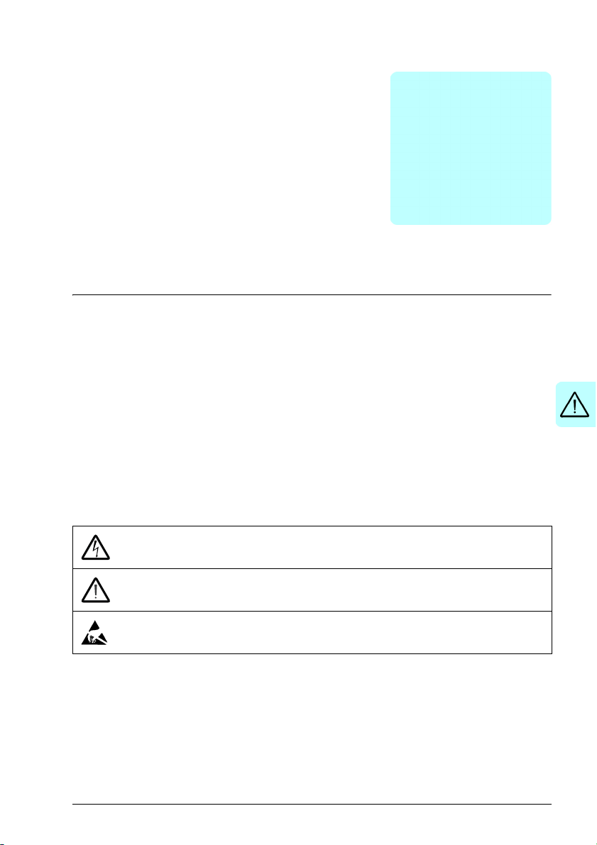
The manual uses these warning symbols:
Electricity warning tells you about hazards from electricity which can
cause injury or death, or damage to the equipment.
General warning tells you about conditions, other than those caused by
electricity, which can cause injury or death, or damage to the equipment.
Electrostatic sensitive devices warning tells you about the risk of
electrostatic discharge which can cause damage to the equipment.
Page 12

12 Safety instructions
General safety in installation, start-up and maintenance
These instructions are for all personnel that install the drive and do maintenance work
on it.
WARNING! Obey these instructions. If you ignore them, injury or death, or
damage to the equipment can occur.
• Handle the drive carefully.
• Use safety shoes with a metal toe cap.
• Keep the drive in its package or protect it otherwise from dust and burr from
drilling and grinding until you install it.
• Vacuum clean the area below the drive before the start-up to prevent the drive
cooling fan from drawing the dust inside the drive.
• Protect also the installed drive against dust and burr. Electrically conductive
debris inside the drive may cause damage or malfunction.
• Do not cover the air inlet and outlet when the drive runs.
• Make sure that there is sufficient cooling.
• Before you connect voltage to the drive, make sure that the drive covers are on.
Keep the covers on during operation.
• Before you adjust the drive operation limits, make sure that the motor and all
driven equipment can operate throughout the set operation limits.
• Before you activate the automatic fault reset or automatic restart functions of the
drive control program, make sure that no dangerous situations can occur. These
functions reset the drive automatically and continue operation after a fault or
supply break. If these functions are activated, the installation must be clearly
marked as defined in IEC/EN 61800-5-1, subclause 6.5.3, for example, “THIS
MACHINE STARTS AUTOMATICALLY”.
• The maximum number of drive power-ups is two per minute. Too frequent powerups can damage the charging circuit of the DC capacitors. The maximum total
number of chargings is 15000.
• If you have connected safety circuits to the drive (for example, emergency stop
and Safe torque off), validate them at the start up.
Note:
• If you select an external source for the start command and it is on, the drive starts
immediately after a fault reset, unless you configure the drive for pulse start.
• When the control location is not set to local, the stop key on the control panel
does not stop the drive.
• Drives can be repaired only by an authorized person.
Page 13

Safety instructions 13
Electrical safety in installation, start-up and maintenance
Precautions before electrical work
These warnings are for all personnel who do work on the drive, motor cable or motor.
WARNING! Obey these instructions. If you ignore them, injury or death, or
damage to the equipment can occur. If you are not a qualified electrician, do
not do electrical installation or maintenance work. Do these steps before you begin
any installation or maintenance work.
1. Clearly identify the work location.
2. Disconnect all possible voltage sources.
• Open the main disconnector at the power supply of the drive.
• Make sure that reconnection is not possible. Lock the disconnector to open
position and attach a warning notice to it.
• Disconnect any external power sources from the control circuits before you do
work on the control cables.
• After you disconnect the drive, always wait for 5 minutes to let the
intermediate circuit capacitors discharge before you continue.
3. Protect any other energized parts in the work location against contact.
4. Take special precautions when close to bare conductors.
5. Measure that the installation is de-energized.
• Use a multimeter with an impedance of at least 1 Mohm.
• Make sure that the voltage between the drive input power terminals (L1, L2,
L3) and the grounding terminal (PE) is close to 0 V.
• Make sure that the voltage between the drive DC terminals (UDC+ and UDC-)
and the grounding terminal (PE) is close to 0 V.
6. Install temporary grounding as required by the local regulations.
7. Ask for a permit to work from the person in control of the electrical installation
work.
Page 14
14 Safety instructions
Additional instructions and notes
WARNING! Obey these instructions. If you ignore them, injury or death, or
damage to the equipment can occur.
• If you install the drive on an IT system (an ungrounded power system or a highresistance-grounded [over 30 ohms] power system), disconnect the internal EMC
filter; otherwise the system will be connected to ground potential through the EMC
filter capacitors. This can cause danger or damage the drive.
Note: Disconnecting the internal EMC filter increases the conducted emission
and reduces the drive EMC compatibility considerably.
• If you connect the drive to an IT system (an ungrounded power system or a highresistance-grounded [over 30 ohms] power system), disconnect the varistor from
ground. Failure to do so can cause damage to the varistor circuit.
• If you install the drive on a corner-grounded TN system, disconnect the internal
EMC filter; otherwise the system will be connected to ground potential through the
EMC filter capacitors. This will damage the drive.
Note: Disconnecting the internal EMC filter increases the conducted emission
and reduces the drive EMC compatibility considerably.
• Use all ELV (extra low voltage) circuits connected to the drive only within a zone
of equipotential bonding, that is, within a zone where all simultaneously
accessible conductive parts are electrically connected to prevent hazardous
voltages appearing between them. You can accomplish this by a proper factory
grounding, that is, make sure that all simultaneously accessible conductive parts
are grounded to the protective earth (PE) bus of the building.
• Do not do insulation or voltage withstand tests on the drive.
Note:
• The motor cable terminals of the drive are at a dangerous voltage when the input
power is on, regardless of whether the motor is running or not.
• The DC and brake resistor terminals (UDC+, UDC-, R+ and R-) are at a
dangerous voltage.
• External wiring can supply dangerous voltages to the terminals of relay outputs.
• The Safe torque off function does not remove the voltage from the main and
auxiliary circuits. The function is not effective against deliberate sabotage or
misuse.
WARNING! Use a grounding wrist band when you handle the printed circuit
boards. Do not touch the boards unnecessarily. The components on the boards
are sensitive to electrostatic discharge.
Page 15

Safety instructions 15
Grounding
These instructions are for all personnel who are responsible for the electrical
installation, including the grounding of the drive.
WARNING! Obey these instructions. If you ignore them, injury or death, or
equipment malfunction can occur, and electromagnetic interference can
increase.
• If you are not a qualified electrician, do not do grounding work.
• Always ground the drive, the motor and adjoining equipment to the protective
earth (PE) bus of the power supply. This is necessary for the personnel safety.
Proper grounding also reduces electromagnetic emission and interference.
• In a multiple-drive installation, connect each drive separately to the protective
earth (PE) bus of the power supply.
• Make sure that the conductivity of the protective earth (PE) conductors is
sufficient. Refer to Selecting the power cables on page 42. Obey the local
regulations.
• Connect the power cable shields to the protective earth (PE) terminals of the
drive.
• Make a 360° grounding of the power and control cable shields at the cable entries
to suppress electromagnetic disturbances.
Note:
• You can use power cable shields as grounding conductors only when their
conductivity is sufficient.
• Standard IEC/EN 61800-5-1 (section 4.3.5.5.2.) requires that as the normal touch
current of the drive is higher than 3.5 mA AC or 10 mA DC, you must use a fixed
protective earth (PE) connection. In addition,
• install a second protective earth conductor of the same cross-sectional area
as the original protective earthing conductor,
or
• install a protective earth conductor with a cross-section of at least 10 mm
or 16 mm2Al,
or
• install a device which automatically disconnects the supply if the protective
earth conductor breaks.
2
Cu
Page 16

16 Safety instructions
Additional instructions for permanent magnet motor drives
Safety in installation, start-up and maintenance
These are additional warnings that apply to permanent magnet motor drives. The
other safety instructions in this chapter are also valid.
WARNING! Obey these instructions. If you ignore them, injury or death and
damage to the equipment can occur.
• Do not work on a drive when a rotating permanent magnet motor is connected
to it. A rotating permanent magnet motor energizes the drive including its input
power terminals.
Before installation, start-up and maintenance work on the drive:
• Stop the motor.
• Disconnect the motor from the drive with a safety switch or by other means.
• If you cannot disconnect the motor, make sure that the motor cannot rotate during
work. Make sure that no other system, like hydraulic crawling drives, can rotate
the motor directly or through any mechanical connection like felt, nip, rope, etc.
• Measure that the installation is de-energized.
• Use a multimeter with an impedance of at least 1 Mohm.
• Make sure that the voltage between the drive output terminals (T1/U, T2/V,
T3/W) and the grounding (PE) busbar is close to 0 V.
• Make sure that the voltage between the drive input power terminals (L1, L2,
L3) and the grounding (PE) busbar is close to 0 V.
• Make sure that the voltage between the drive DC terminals (UDC+, UDC-) and
the grounding (PE) terminal is close to 0 V.
• Install temporary grounding to the drive output terminals (T1/U, T2/V, T3/W).
Connect the output terminals together as well as to the PE.
Start-up and operation:
• Make sure that the operator cannot run the motor over the rated speed. Motor
overspeed causes overvoltage that can damage or explode the capacitors in the
intermediate circuit of the drive.
Page 17

Safety instructions 17
General safety in operation
These instructions are for all personnel that operate the drive.
WARNING! Obey these instructions. If you ignore them, injury or death, or
damage to the equipment can occur.
• Do not control the motor with the disconnector at the drive power supply. Use the
control panel start and stop keys or the start/stop commands from an external
control device connected through the I/O or fieldbus interface.
• Give a stop command to the drive before you reset a fault. If you have an external
source for the start command and the start is on, the drive will start immediately
after the fault reset, unless you configure the drive for pulse start. See the
firmware manual.
• Before you activate automatic fault reset functions of the drive control program,
make sure that no dangerous situations can occur. These functions reset the
drive automatically and continue operation after a fault.
Note: When the control location is not set to Local, the stop key on the control panel
will not stop the drive.
Page 18

18 Safety instructions
Page 19

Introduction to the manual 19
2
Introduction to the manual
Contents of this chapter
The chapter describes the applicability, target audience and purpose of this manual. It
describes the contents of this manual. The chapter also has a flowchart for the
delivery, installation and commissioning of the drive.
Applicability
The manual applies to ACH480 drives.
Target audience
The reader must know the fundamentals of electricity, wiring, electrical components
and electrical schematic symbols.
Purpose of the manual
This manual has the information needed to plan the installation, and install,
commission and service the drive.
Page 20

20 Introduction to the manual
Contents of this manual
• Safety instructions (on page 11) gives the safety instructions that you must obey
when you install, commission, operate and service the drive.
• Introduction to the manual (on page 19) describes the applicability, target
audience, purpose and contents of this manual.
• Hardware description (on page 25) describes the operation principle, layout,
power connections and control interfaces, type designation information.
• Mechanical installation (on page 35) describes how to examine the installation
site, unpack, examine the delivery and install the drive mechanically.
• Planning the electrical installation (on page 41) describes how to plan the
electrical installation of the drive.
• Electrical installation (on page 55) describes how to measure the insulation of the
assembly and the compatibility with IT (ungrounded) and corner-grounded TN
systems. It shows how to connect the power and control cables, install optional
modules and connect a PC.
• Installation checklist (on page 73) contains a checklist for the mechanical and
electrical installation of the drive before start-up.
• Maintenance (on page 75) contains the preventive maintenance instructions and
LED indicator descriptions.
• Technical data (on page 83) contains the technical specifications of the drive.
• Dimension drawings (on page 111) shows the dimension drawings of the drive.
• Resistor braking (on page 121) tells you how to select the brake resistor.
• Safe torque off function (on page 129) describes the STO features, installation
and technical data.
• BAPO-01 power extension module (on page 143) describes the optional BAPO01 module.
• BIO-01 I/O extension module (on page 147) decribes the optional I/O extension
module.
Related documents
Refer to List of related manuals on page 2 (the inner front cover).
Categorization by frame (size)
The drive is manufactured in frame sizes, for example, R0, R1, R2 and so on.
Information that is applicable only to certain frames shows the frame size. Some
instructions only apply to specific frame sizes. You can read the frame size from the
type designation label on the drive, refer to Drive labels on page 30.
Page 21
Introduction to the manual 21
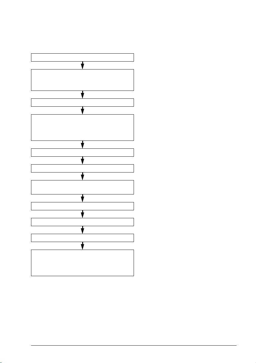
Quick installation and commissioning flowchart
Task Refer to
Identify the frame size: R0, R1, R2, etc. Type designation key on page 32.
Plan the installation.
Check the ambient conditions, ratings and
required cooling air flow.
Unpack and check the drive. Unpacking the delivery on page 37.
If the drive is connected to an IT (ungrounded)
system or corner-grounded TN system, make
sure that the internal EMC filter is not
connected.
Install the drive. Installing the drive on page 38.
Route the cables. Routing the cables on page 49.
Measure the insulation of the input cable,
motor and motor cable.
Connect the power cables. Connecting the power cables on page 59.
Connect the control cables. Connecting the control cables on page 62.
Examine the installation. Installation checklist on page 73.
Planning the electrical installation on page 41.
Technical data on page 83.
Type designation key on page 32.
Compatibility with IT (ungrounded) and
corner-grounded TN systems on page 57.
Measuring insulation on page 56.
Commission the drive. Refer to the ACH480 drives quick installation
guide (3AXD50000247141 [English]) and the
ACH480 drives firmware manual
(3AXD50000247134 [English]).
Page 22

22 Introduction to the manual
Terms and abbreviations
Term/abbreviation Explanation
ACX-AP-X Assistant control panel. An advanced operator keypad for
BACnet™ BACnet™ is a registered trademark of American Society of Heating,
Brake chopper Conducts the surplus energy from the intermediate circuit of the drive to
Brake resistor Dissipates the drive surplus braking energy conducted by the brake
Capacitor bank Refer to DC link capacitors.
CDPI-02 Communication adapter module
Control board Circuit board in which the control program runs.
BAPO-01 Optional side-mounted auxiliary power extension module
BCBL-01 Optional USB to RJ45 cable
BIO-01 Optional I/O extension module underneath the fieldbus option
CCA-01 Optional cold configuration adapter
DC link DC circuit between rectifier and inverter
DC link capacitors Energy storage which stabilizes the intermediate circuit DC voltage
DPMP-01 Mounting platform for ACX-AP control panel (flange mounting)
DPMP-02 Mounting platform for ACX-AP control panel (surface mounting)
Drive Frequency converter for controlling AC motors
EFB Embedded fieldbus
EMC Electromagnetic compatibility
FBA Fieldbus adapter
FBIP-21 Optional BACnet/IP adapter module
FCAN-01 Optional CANopen adapter module
FCNA-01 Optional ControlNet adapter module
FDNA-01 Optional DeviceNet adapter module
FECA-01 Optional EtherCAT adapter module
FENA-21 Optional Ethernet adapter module for EtherNet/IP, Modbus TCP and
FEPL-02 Optional Ethernet POWERLINK adapter module
FLON-01 Optional LONWORKS adapter module
FPBA-01 Optional PROFIBUS DP adapter module
FSCA-01 Optional RS-485 adapter module
communication with the drive.
Refrigerating and Air-Conditioning Engineers (ASHRAE).
the brake resistor when necessary. The chopper operates when the DC
link voltage exceeds a certain maximum limit. The voltage rise is
typically caused by deceleration (braking) of a high inertia motor.
chopper to heat. Essential part of the brake circuit. Refer to Brake
chopper.
PROFINET IO protocols
Page 23

Introduction to the manual 23
Term/abbreviation Explanation
Frame (size) Refers to drive physical size, for example, R0 and R1. The type
I/O Input/Output
IGBT Insulated gate bipolar transistor
Intermediate circuit Refer to DC link.
Inverter Converts direct current and voltage to alternating current and voltage.
Macro Pre-defined default set of parameters in a drive control program. Each
NETA-21 Optional remote monitoring tool
Network control With fieldbus protocols based on the Common Industrial Protocol
Parameter User-adjustable operation instruction to the drive, or signal measured or
PLC Programmable logic controller
PROFIBUS,
PROFIBUS DP,
PROFINET IO
R0, R1, R2, R3… Frame (size)
RCD Residual current device
Rectifier Converts alternating current and voltage to direct current and voltage.
RFI Radio-frequency interference
SIL Safety integrity level. Refer to Safe torque off function on page 129.
STO Safe torque off. Refer to Safe torque off function on page 129.
designation label attached to the drive shows the frame of the drive,
refer to Type designation key on page 32.
macro is intended for a specific application.
TM
), such as DeviceNet and Ethernet/IP, denotes the control of the
(CIP
drive using the Net Ctrl and Net Ref objects of the ODVA AC/DC Drive
Profile. For more information, refer to
www.odva.org, and to FDNA-01
DeviceNet adapter module user’s manual (3AFE68573360 [English])
and FENA-01/-11/-21 Ethernet adapter module user’s manual
(3AUA0000093568 [English]).
calculated by the drive
Registered trademarks of PI - PROFIBUS & PROFINET International
Page 24

24 Introduction to the manual
Page 25

Hardware description 25
3
Hardware description
Contents of this chapter
This chapter describes the operation principle, layout, type designation label and type
designation information. It shows a general diagram of the power connections and
control interfaces.
General description
The ACH480 is a drive for controlling asynchronous AC induction motors, permanent
magnet synchronous motors and ABB synchronous reluctance motors (SynRM
motors). It is optimized for cabinet mounting.
Product variants
The drive has two primary products:
• Standard unit (for example, ACH480-04-02A7) with the Assistant control panel
ACH-AP-H and an I/O module with integrated EIA-485 RIIO-01.
• Base unit (for example, ACH480-04-02A7+0J400+0L540) without a control panel
and without an I/O module RIIO-01 with EIA-485.
Refer to Type designation key on page 32.
Page 26
26 Hardware description
1
2
4
5
6
7
9
12
14
16
10
8
15
11
13
3
17
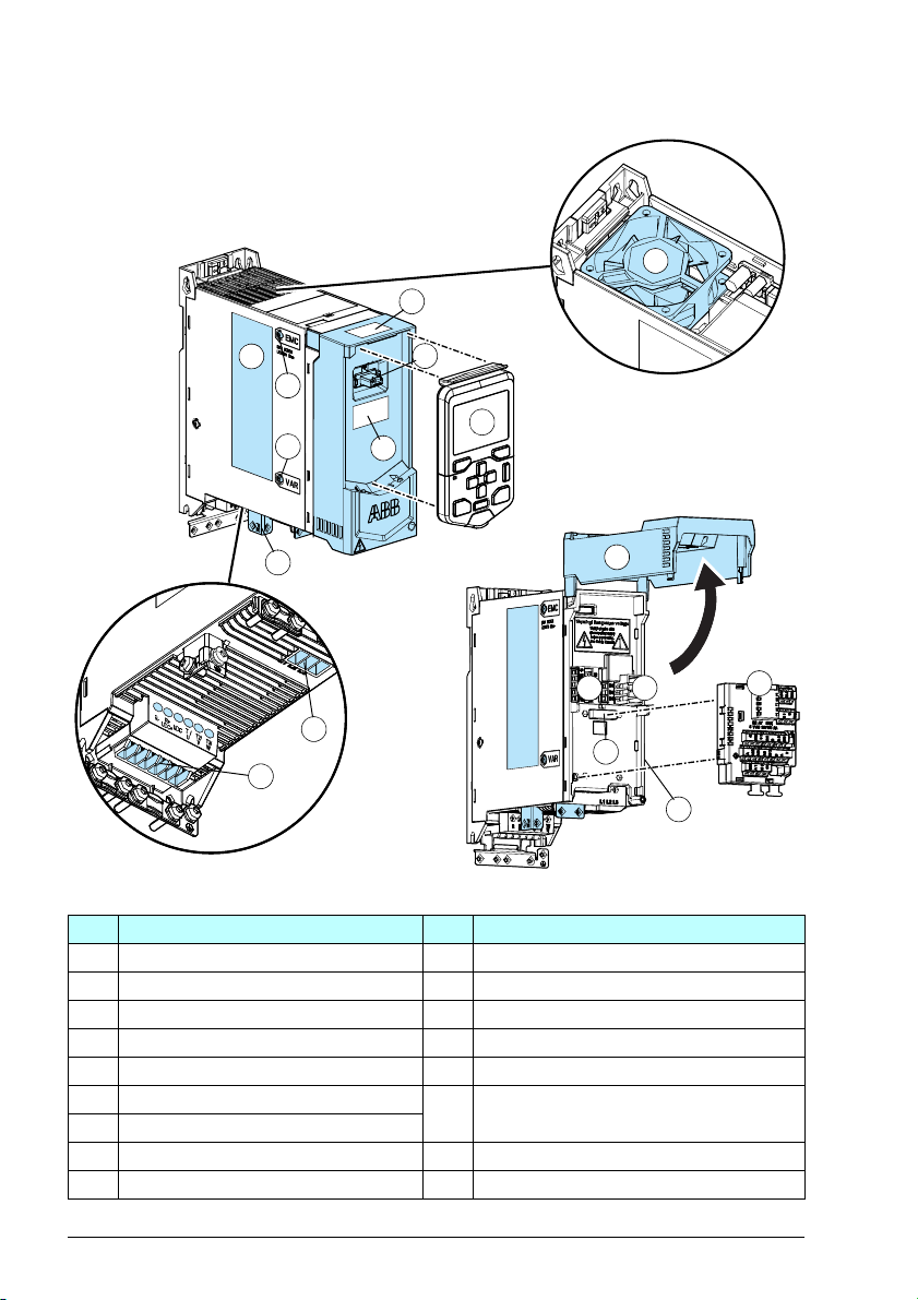
Hardware overview
No. Description No. Description
1 Type designation label 10 Motor and braking resistor terminals
2 Model information label 11 Cooling fan (not on R0)
3 Software information label 12 Front cover
4 Control panel connection 13 Fixed control terminals
5 Control panel 14 Cold configuration connection (CCA-01)
6 EMC filter grounding screw 15 Slot for front option modules
7 Varistor grounding screw
8 PE connection (motor) 16 I/O or fieldbus module
9 Input power terminal 17 Side option slot for side-mounted options
(I/O module or fieldbus module)
Page 27
Hardware description 27
RELAYS MAX
250V AC 30 DC 2A
24V
DGND
DCOM
D 3
D 4
D 5
D 6
AI2
AGND
A01
A02
AGND
B +
A -
DGND
SCR
AI1
AGND
+10V
RO2C
R02A
RO2B
RO3C
R 3A
RO3B
D 1
DI2
IN1
IN2
ON
RO C
RO1A
RO1B
+24V
DGND
DCOM
SGND
OUT1
1
1
2
3
4
5
8
10
7
9
6
11
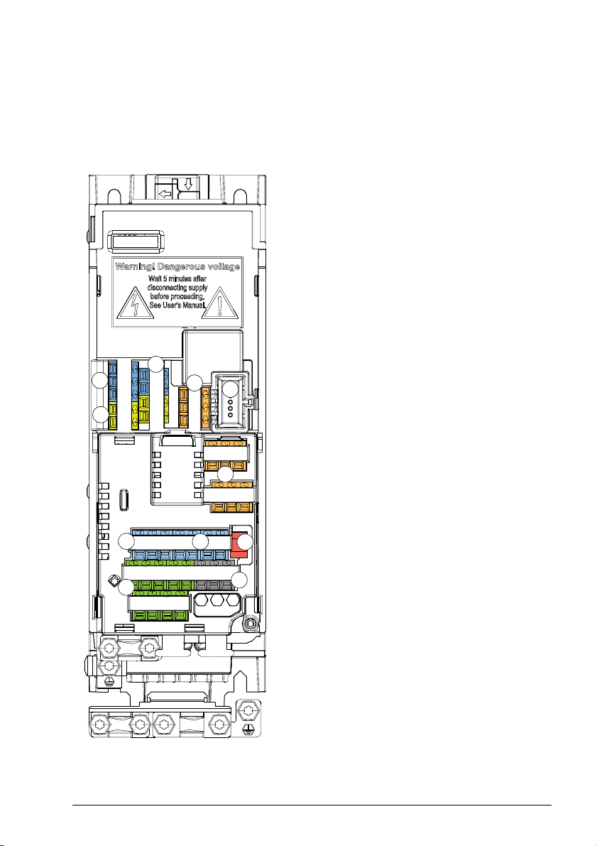
Control connections
There are fixed control connections on the base unit and optional control connections
based on the installed option module.
Standard unit
Connections of the base unit:
1. Auxiliary voltage outputs
2. Digital inputs
3. Safe torque-off connections
4. Relay output connection
5. Cold configuration connection for CCA-01
Connections of the standard I/O module
RIIO-01:
6. Digital inputs
7. Analog inputs and outputs
8. Relay output connections
9. Embedded fieldbus EIA-485 (BACnet
MS/TP, Modbus RTU, N2)
10. Auxiliary voltage output
11.Termination switch and bias resistor switch
Page 28

28 Hardware description
D 1
DI2
IN1
IN2
+24V
DGND
DCOM
SGND
OUT1
RO C
RO1A
RO1B
1
2
3
4
5
6
Base unit
Connections of the base unit:
1. Auxiliary voltage outputs
2. Digital inputs
3. Safe torque-off connections
4. Relay output connection
5. Cold configuration connection for CCA-01
6. Front option module slot 1
Page 29

Hardware description 29
Mounted options
For information on mounted optional modules, refer to:
• BAPO-01 power extension module on page 143.
• BIO-01 I/O extension module on page 147.
Control panel
The drive supports these assistant control panels:
• ACH-AP-H (included in the standard delivery)
•ACH-AP-W
• CDPI-02 communication adapter module
For information on the assistant control panels, refer to the ACX-AP-x Assistant
control panels user’s manual (3AUA0000085685 [EN]).
For information on how to start up the drive, and modify the settings and parameters,
refer to the ACH480 drives firmware manual (3AXD50000247134 [English]).
PC connection
To connect a PC to the drive, there are two alternatives:
1. Use an ACH-AP-H/ACH-AP-W assistant control panel as a converter with a USB
Mini-B type cable.
2. Use a USB to RJ45 converter BCBL-01 (3AXD50000032449) with CDPI-02
(3AXD50000009929).
For information on the Drive composer PC tool, refer to Drive composer PC tool
user's manual (3AUA0000094606 [English]).
Page 30
30 Hardware description
AC,480-04-04A1-4
S/N: 1170301940
1
2
3
AC,480-04-04A1-4
3~400V/480 V (frame R1)
Pld: 1.5 kW (2 hp)
Phd: 1.1 kW (1.5 hp)
SW v2.02.0.8
1
2
3
5
4
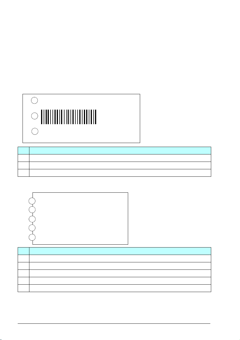
Drive labels
The drive has these labels:
• Model information label on the top of the drive
• Software information label on the front cover
• Type designation label on the left side of the drive
For label positions, refer to Hardware overview on page 26.
Model information label
No. Description
1 Drive type
2 Bar code
3 Serial number
Software information label
No. Description
1 Drive type
2 Input voltage rating and frame size
3 Typical motor power in light-duty use (10% overload)
4 Typical motor power in heavy-duty use (50% overload)
5 Drive software version
Page 31

Type designation label
ABB Oy
,ŝŽŵŽƟĞϭϯ
ϬϬϯϴϬ,ĞůƐŝŶŬŝ
&ŝŶůĂŶĚ
,ϰϴϬͲϬϰͲϬϰϭͲϰ
ŝƌĐŽŽůŝŶŐ
/ĐĐϭϬϬŬIP20
h>ŽƉĞŶƚLJƉĞ
FRAME
Zϭ
/ŶƉƵƚ
KƵƚƉƵƚ
^EϭϭϳϬϯϬϭϵϰϬ
hϭ
Ĩϭ
U2
/ůĚ
/ŚĚ
f2
ϯΕϰϬϬϰϴϬs
50/60 Hz
ϯΕϬhϭ
ϯϴϯϰ
ϯϯϯ
Ϭϱϵϵ,nj
IND.CONT.EQ.
1PDS
/ŶƉƵƚĐƵƌƌĞŶƚŝƐƐĐĂůĞĚďLJ
ŵŽƚŽƌŽƵƚƉƵƚĐƵƌƌĞŶƚ
KƵƚƉƵƚ
4
ϯϴϯϰ
ϯϯϯ
/ŶƉƵƚ
ϲϰϱϰ
ϲϭϱϰ
ϱϯϰϴ
/ŶƉƵƚ;ǁŝƚŚ
ϱйĐŚŽŬĞͿ
ϰϯϰ
ϯϴϯϰ
ϯϯϯ
e
1
2
3
4
5
6
This is a sample type designation label.
No. Description
1 Type designation, refer to Type designation key on page 32.
2Frame (size)
3 Degree of protection
4 Nominal ratings, refer to Ratings on page 84.
5 Valid markings
6 S/N: Serial number of format MYYWWXXXX, where
M:
YY:
WW:
XXXX:
Manufacturer
Year of manufacture: 15, 16, 17, … for 2015, 2016, 2017, …
Week of manufacture: 01, 02, 03, … for week 1, week 2, week 3, …
Running item number that starts each week from 0001.
Hardware description 31
Page 32

32 Hardware description
Type designation key
The type designation tells you the specifications and configuration of the drive. For
more information on the ratings, refer to Technical data on page 83.
Sample type code: ACH480-04-12A7-4+XXXX
Segment A B C D
ACH480 - 04 - 02A7 - 4 + Option codes
Code Description
Basic codes
A Construction 04 = Module, IP20
04 When there aro no options: cabinet optimized module, IP20, assistant
control panel with USB, I/O module with embedded Modbus RTU, EMC
C2 filter (internal EMC filter), safe torque off, braking chopper, coated
boards, quick installation and start-up guide.
B Drive size
e.g. 12A7 Nominal output current rating of the inverter.
C Voltage rating
4 3-phase 380...480 V AC
D Option codes (plus codes)
Control panel and panel options
J400 ACH-AP-H Assistant control panel
J429 ACH-AP-W Assistant control panel with Bluetooth interface
0J400 Without control panel
I/O
L515 BIO-01 I/O extension module (front option, can be used with a fieldbus
module)
L534 BAPO-01 External 24 V DC (side option)
L540 Standard I/O module RIIO-01 with embedded EIA-485 (front option,
cannot be used with a fieldbus module)
0L540 Without standard I/O module RIIO-01 with embedded EIA-485
Fieldbus adapters
K451 FDNA-01 DeviceNet
K454 FPBA-01 PROFIBUS DP adapter module
K457 FCAN-01 CANopen adapter module
K458 FSCA-01 RS-485 adapter module
K462 FCNA-01 ControlNet
K465 FBIP-21 BACnet/IP adapter module
K469 FECA-01 EtherCAT adapter module
K470 FEPL-02 Ethernet POWERLINK adapter module
TM
adapter module
TM
adapter module
Page 33

Code Description
K475 FENA-21 Ethernet adapter module
K491 FMBT-21 Modbus/TCP adapter module
K492 FPNO-21 Profinet adapter module
Documentation
+R700 English
+R701 German
+R702 Italian
+R703 Dutch
+R704 Danish
+R705 Swedish
+R706 Finnish
+R707 French
+R708 Spanish
+R709 Portuguese
(in Portugal)
+R711 Russian
+R714 Turkish
Hardware description 33
Full set of printed manuals in
the selected language. An
English manual is included, if a
translation is not available.
The product package includes
the Quick installation and start-
up guide.
Page 34

34 Hardware description
R-
L1
L2
L3
T1/U
T2/V
T3/W
R+
1
2
3
4
Operation principle
The figure shows the simplified main circuit diagram of the drive.
No. Description
1 Rectifier. Converts alternating current and voltage to direct current and voltage.
2 DC link. DC circuit between rectifier and inverter.
3 Inverter. Converts direct current and voltage to alternating current and voltage.
4 Brake chopper. Conducts the surplus energy from the intermediate DC circuit of the
drive to the brake resistor when it is necessary and if an external brake resistor is
connected to the drive. The chopper operates when the DC link voltage exceeds a
certain maximum limit. The voltage rise is typically caused by deceleration (braking) of
a motor. The user obtains and installs the brake resistor when needed.
Page 35

Mechanical installation 35
4
Mechanical installation
Contents of this chapter
The chapter tells you how to examine the installation site, unpack, check the delivery
and install the drive mechanically.
Installation alternatives
You can install the drive:
• With screws on to a wall
• With screws on to an assembly plate
• On to a DIN installation rail (with the integrated lock)
Installation requirements:
• Make sure that there is a minimum of 75 mm of free space at the top and bottom
of the drive (at the cooling air inlet and outlet).
• You can install several drives side by side. Note that side-mounted options require
20 mm of space on the right side of the drive.
• Install R0 drives upright. R0 drives do not have a cooling fan.
• You can install R1, R2, R3 and R4 drives tilted by up to 90 degrees from vertical to
fully horizontal orientation.
• Make sure that the cooling air exhaust at the top of the drive is not below the
cooling air inlet at the bottom of the drive.
Page 36

36 Mechanical installation
• Make sure that the hot exhaust air from a drive does not flow into the cooling inlet
of other drives or equipment.
• The drive has an IP20 ingress protection classification for cabinet installation.
Examining the installation site
Make sure that:
• There is sufficient cooling. Refer to Losses, cooling data and noise on page 93.
• The operating conditions are within the specifications in Ambient conditions on
page 101.
• The installation surface is as close to vertical as possible, of non-flammable
material and strong enough to support the drive. Refer to Dimensions and weights
on page 92.
• The material above and below the drive is non-flammable.
• There is sufficient free space above and below the drive for service and
maintenance.
Required tools
To install the drive mechanically, you need the following tools:
• A drill and suitable drill bits
• A screwdriver or wrench with a set of suitable bits (PH0–3, PZ0–3, T15–40, S4–7)
(For motor cable terminals, the recommended shaft length is 150 mm)
• A tape measure and spirit level
• Personal protective equipment
Page 37

Mechanical installation 37
Unpacking the delivery
Make sure that all of the items are present and that there are no signs of damage.
Standard drive package contents:
•Drive
• Assistant control panel (not installed)
• I/O module RIIO-01 with EIA-485 (BACnet MS/TP, Modbus RTU, N2) (not
installed)
• Mounting template (for R3 and larger drives)
• Installation accessories (cable clamps, cable ties, hardware, etc.)
• Options, if ordered with a plus code. Note that if a fieldbus adapter is ordered, it
replaces the I/O module RIIO-01 with EIA-485 of the standard delivery.
• Multilingual warning sticker sheet (residual voltage warning)
• Safety instructions
• Quick installation and start-up guide
• Hardware and Firmware manuals, if ordered with a plus code
Page 38

38 Mechanical installation
W
H
1
2
3
4
5
Installing the drive
You can install the drive:
• With screws to a suitable surface
• To a DIN installation rail with the integrated lock
To install the drive with screws
1. Mark the surface for the mounting holes.
Refer to Dimensions and weights on
page 92. Use the supplied mounting
template for the R3 and R4 frames.
2. Drill the holes for the mounting screws.
3. Start to tighten the screws into the
mounting holes.
4. Install the drive onto the mounting
screws.
5. Tighten the mounting screws.
Page 39

To install the drive to a DIN installation rail
1
2
3
1
2
3
1. Move the locking part to the left.
2. Push and hold the locking button down.
3. Put the top tabs of the drive onto the top
edge of the DIN installation rail.
4. Put the drive against the bottom edge of
the DIN installation rail.
5. Release the locking button.
6. Move the locking part to the right.
7. Make sure that the drive is correctly
installed.
To remove the drive, use a flat-head
screwdriver to open the locking part.
Mechanical installation 39
Page 40

40 Mechanical installation
Page 41

Planning the electrical installation 41
5
Planning the electrical installation
Contents of this chapter
This chapter contains the instructions to plan the electrical installation of the drive, for
example, to check the compatibility of the motor and drive, and select the cables,
protections as well as cable routing.
Make sure that the installation is designed and done according to the applicable local
laws and regulations. ABB does not assume any liability whatsoever for any
installation which breaches the local laws and/or other regulations. If the
recommendations given by ABB are not followed, the drive may experience problems
that the warranty does not cover.
Selecting the supply disconnecting device
Install a hand-operated input disconnecting device between the AC power source
and the drive. You must be able to lock the disconnecting device to the open position
for installation and maintenance work.
European Union
To meet the European Union Directives, according to standard EN 60204-1, Safety of
Machinery, the disconnecting device must be one of the following types:
• Switch-disconnector of utilization category AC-23B (EN 60947-3).
• Disconnector that has an auxiliary contact that in all cases causes switching
devices to break the load circuit before the opening of the main contacts of the
disconnector (EN 60947-3).
• Circuit breaker suitable for isolation in accordance with EN 60947-2.
Page 42

42 Planning the electrical installation
Other regions
The disconnecting device must conform to the applicable local safety regulations.
Checking the compatibility of the motor and drive
Use an asynchronous AC induction motor, permanent magnet motor or synchronous
reluctance motor (SynRM) with the drive. Several induction motors can be connected
to the drive at a time.
Make sure that the motor and the drive are compatible according to the rating table in
Ratings on page 84. The table lists the typical motor power for each drive type.
Selecting the power cables
• Select the input power and motor cables according to the local regulations
• Make sure that the input power and the motor cables can carry the corresponding
load currents. Refer to Ratings on page 84.
• Make sure that the cable is rated for at least 70
temperature of the conductor in continuous use. For the US, refer to Additional
US requirements on page 46.
• The conductivity of the PE conductor must be sufficient, see below.
• A 600 V AC cable is accepted for up to 500 V AC.
• To comply with the EMC requirements of the CE mark, use an approved cable
type. Refer to Recommended power cable types on page 45.
Use a symmetrical shielded cable to decrease:
• The electromagnetic emissions of the drive system.
• The stress on the motor insulation.
• The bearing currents.
°C maximum permissible
Make sure that the protective conductor has adequate conductivity.
Unless local wiring regulations state otherwise, the cross-sectional area of the
protective conductor must agree with the conditions that require automatic
disconnection of the supply required in 411.3.2. of IEC 60364-4-41:2005, and be
capable of withstanding the prospective fault current during the disconnection time of
the protective device.
You can select the cross-sectional area of the protective conductor from the table
below or calculate it according to 543.1 of IEC 60364-5-54.
This table shows the minimum cross-sectional area related to the phase conductor
size according to IEC 61800-5-1 when the phase conductor and the protective
conductor are made of the same metal. If this is not so, select the cross-sectional
area of the protective earthing conductor in a manner that produces a conductance
equivalent to that which results from the application of this table:
Page 43

Planning the electrical installation 43
Cross-sectional area of the phase
conductors S (mm
16 S
S <
16 < S <
35 < S S/2
2
)
35 16
Minimum cross-sectional area of the
protective conductor S
(mm2)
p
Refer to the IEC/EN 61800-5-1 requirement on grounding on page 15.
Typical power cable sizes
These are the typical cross-sectional area of the power cables at the nominal drive
current.
Typ e
ACH480-04-…
1-phase U
02A4-1 R0 3×1.5 + 1.5 16
03A7-1 R0 3×1.5 + 1.5 16
04A8-1 R1 3×1.5 + 1.5 16
06A9-1 R1 3×1.5 + 1.5 16
07A8-1 R1 3×1.5 + 1.5 16
09A8-1 R2
12A2-1 R2
3-phase U
02A4-2 R1 3×1.5 + 1.5
03A7-2 R1 3×1.5 + 1.5 16
04A8-2 R1
06A9-2 R1
07A8-2 R1
09A8-2 R1 3×2.5 + 2.5
12A2-2 R2 3×2.5 + 2.5
17A5-2 R3 3×6 + 6
25A0-2 R3
032A-2 R4
048A-2 R4
055A-2 R4
3-phase UN= 380…480 V
02A7-4 R1 3×1.5 + 1.5 16
03A4-4 R1 3×1.5 + 1.5 16
= 200…240 V
N
= 200…240 V
N
Frame mm2 (Cu)
3×2.5 + 2.5 14
3×2.5 + 2.5 14
3×1.5 + 1.5
3×1.5 + 1.5
3×1.5 + 1.5
3×10 + 10
3×25 + 16
3×25 + 16
(1
3×6 + 6 10
AWG
16
16
16
16
14
14
14
8
4
4
Page 44

44 Planning the electrical installation
Typ e
Frame mm2 (Cu)
(1
AWG
ACH480-04-…
04A1-4 R1 3×1.5 + 1.5 16
05A7-4 R1 3×1.5 + 1.5 16
07A3-4 R1 3×1.5 + 1.5 16
09A5-4 R1 3×2.5 + 2.5 14
12A7-4 R2 3×2.5 + 2.5 14
018A-4 R3 3×6 + 6 10
026A-4 R3 3×6 + 6 10
033A-4 R4 3×10 + 10 8
039A-4 R4 3×16 + 16 6
046A-4 R4 3×25 + 16 4
050A-4 R4 3×25 + 16 4
1) This is the size of a typical power cable (symmetrical, shielded, three-phase copper cable). Note that for the
input power connection, you typically must have two separate PE conductors, that is, the shield alone is not
sufficient. Refer to Grounding on page 15.
Refer also to Terminal data for the power cables on page 94.
Page 45

Recommended power cable types
PE
PE
PE
PE
PVC
EMT
PE
Symmetrical shielded cable with three phase conductors and a
concentric PE conductor as the shield. The shield must meet the
requirements of IEC 61800-5-1 (refer to page 42). Make sure that
local/state/country electrical codes permit this cable type.
Symmetrical shielded cable with three phase conductors and a
concentric PE conductor as the shield. A separate PE conductor is
required if the shield does not meet the requirements of IEC 61800-5-1
(refer to page 42).
Symmetrical shielded cable with three phase conductors and
symmetrically constructed PE conductor, and a shield. The PE conductor
must meet the requirements of IEC 61800-5-1 (refer to page 42).
Power cable types for limited use
A four-conductor system (three phase conductors and a protective
conductor on a cable tray) is not permitted for motor cabling (it is
permitted for input cabling).
A four-conductor system (three phase conductors and a PE conductor in
a PVC conduit) is permitted for input cabling with a phase conductor
cross-section less than 10 mm
Not permitted in the USA.
Planning the electrical installation 45
2
(8 AWG) or for motors < 30 kW (40 hp).
Corrugated or EMT cable with three phase conductors and a protective
conductor is permitted for motor cabling with a phase conductor cross
section less than 10 mm
Not allowed power cable types
Symmetrical shielded cable with individual shields for each phase
conductor is not permitted in any cable size for input or motor cabling.
2
(8 AWG) or for motors < 30 kW (40 hp).
Page 46

46 Planning the electrical installation
1
3 4 5
2
Motor cable shield
If the motor cable shield is the only protective earth conductor of the motor, make
sure that the conductivity of the shield is sufficient. Refer to Selecting the power
cables on page 42 or to IEC 61800-5-1.
To effectively suppress radiated and conducted radio-frequency emissions, the cable
shield conductivity must be at least 1/10 of the phase conductor conductivity. To meet
the requirements, use a copper or an aluminum shield. The figure shows the
minimum requirements for the motor cable shield. It has a concentric layer of copper
wires with an open helix of copper tape or copper wire. The better and tighter the
shield, the lower the emissions and bearing currents.
No. Description
1 Insulation jacket
2 Helix of copper tape or copper wire
3 Copper wire shield
4 Inner insulation
5 Cable conductors
Additional US requirements
Use type MC continuous corrugated aluminum armor cable with symmetrical grounds
or shielded power cable for the motor cables if metallic conduit is not used. For the
North American market, 600 V AC cable is accepted for up to 500 V AC. A 1,000 V
AC cable is required above 500 V AC (below 600 V AC). The power cables must be
rated for 75
Conduit
Couple separate parts of a conduit together: Bridge the joints with a ground conductor
that is bonded to the conduit on each side of the joint. Also bond the conduits to the
drive enclosure and motor frame. Use separate conduits for input power, motor, brake
resistor and control wiring. When a conduit is used, type MC continuous corrugated
aluminum armor cable or shielded cable is not required. A dedicated ground cable is
always required.
Do not run motor wiring from more than one drive in the same conduit.
°C (167 °F).
Page 47

Planning the electrical installation 47
Armored cable or shielded power cable
Six-conductor (three phase and three ground conductors) type MC continuous
corrugated aluminum armor cable with symmetrical grounds is available from the
following suppliers (trade names in parentheses):
• Anixter Wire & Cable (VFD)
• RSCC Wire and Cable (Gardex)
• Okonite (CLX)
Shielded power cables are available from the following suppliers:
• Belden
• LAPPKABEL (ÖLFLEX)
• Pirelli
Page 48

48 Planning the electrical installation
a b
Selecting the control cables
Shielding
Only use shielded control cables.
Use a double-shielded twisted pair cable (a) for analog signals. Use one individually
shielded pair for each signal. Do not use a common return for different analog
signals.
A double-shielded cable (a) is the best alternative for low-voltage digital signals, but a
single-shielded (b) twisted pair cable is acceptable.
Signals in separate cables
Put analog and digital signals in separate, shielded cables.
Do not mix 24 V
and 115/230 V AC signals in the same cable.
Signals that can be run in the same cable
If their voltage does not exceed 48 V, relay-controlled signals can be in the same
cables as digital input signals. The relay-controlled signals should be run as twisted
pairs.
Relay cable
The cable type with braided metallic screen (for example ÖLFLEX by LAPPKABEL,
Germany) has been tested and approved by ABB.
Control panel to PC connection
Use a USB type A (PC) – type B (control panel) cable. The maximum permitted
length of the cable is 3 m (9.8 ft).
Control panel to drive connection
Use EIA-485 with male RJ-45 connector, cable type CAT 5e or better. The maximum
permitted length of the cable is 100 m (328 ft).
Modbus RTU cable
For the cable specification see Control connection data on page 99.
Page 49

Planning the electrical installation 49
I
C
M
Routing the cables
Select the cable routes as follows:
• Put the input power cable (I), motor
cable (M) and control cables (C) into
separate trays.
• Put the motor cable (M) away from
the other cables.
• Make sure that there is a minimum of
200 mm between the input power
cable (I) and the control cables (C).
• Make sure that there is a minimum of
500 mm between the motor cable (M)
and the control cables (C).
• Make sure that there is a minimum
300 mm between the input power
cable (I) and the motor cable (M).
• If the control cables cross the input
power or motor cables, put the cables
at 90 degrees to each other.
• You can put several motor cables in
parallel.
• Do not install other cables in parallel
with the motor cables.
• Make sure that the cable trays are
electrically bonded to each other and
to the electrical ground.
• Make sure that the control cables are approriately supported outside the drive to
relieve stress on the cables.
WARNING! Make sure that there are no sources of strong magnetic fields
such as high-current single-core conductors or contactor coils near the drive. A
strong magnetic field can cause interference or inaccuracy in the operation of
the drive. If there is interference, move the source of the magnetic field away
from the drive.
Page 50

50 Planning the electrical installation
Separate control cable ducts
Put 24 V and 230 V (120 V) control cables in separate ducts unless the 24 V cable is
insulated for 230 V (120 V) or insulated with an insulation sleeving for 230 V (120 V).
Continuous motor cable shield or conduit
To minimize the emission level when there are safety switches, contactors,
connection boxes or similar equipment on the motor cable between the drive and the
motor: Install the equipment in a metal enclosure with 360 degree grounding for the
shields of both the incoming and outgoing cables, or connect the shields otherwise
together. If cabling is put into conduits, make sure that they are continuous.
Implementing short-circuit protection
Protecting the drive and input power cable in short-circuits
Protect the drive and input cable with fuses. For fuse ratings, refer to Technical data
on page 83. The fuses protect the input cable, restrict drive damage and prevent
damage to adjoining equipment if there is a short-circuit.
For information on circuit breakers, contact ABB for more information.
Protecting the motor and motor cable in short-circuits
If the motor cable has the correct size for the nominal current, the drive protects the
motor cable and motor if there is a short-circuit.
Page 51

Planning the electrical installation 51
Implementing thermal overload protection
Protecting the drive, and the input power and motor cables against
thermal overload
If the cables have the correct size for the nominal current, the drive protects itself and
the input and motor cables against thermal overload.
WARNING! If the drive is connected to several motors, use a separate circuit
breaker or fuses to protect each motor cable and motor against overload. The
drive overload protection is tuned for the total motor load. It may not trip due to an
overload in one motor circuit only.
Protecting the motor against thermal overload
According to the regulations, the motor must be protected against thermal overload
and the current must be switched off when an overload is detected. The drive has a
motor thermal protection function that protects the motor and switches off the current
when necessary. Depending on a drive parameter value, the function either monitors
a calculated temperature value or an actual temperature indication given by motor
temperature sensors. The user can tune the thermal model by feeding in additional
motor and load data.
The most common temperature sensors are:
• For motor sizes IEC180…225: a thermal switch, for example, a Klixon.
• For motor sizes IEC200…250 and larger: a PTC or Pt100 sensor.
Note: PTC can be used by connecting it through analog input and output. Configure
supervision parameters to give a warning and fault.
Protecting the drive against ground faults
The drive has a ground fault protection function that protects the unit against ground
faults in the motor and motor cable. It is not a personnel safety or a fire protection
feature.
Residual current device compatibility
The drive can be used with residual current devices of Type B.
Note: The EMC filter of the drive has capacitors between the main circuit and the
frame. These capacitors and long motor cables increase the ground leakage current
and can cause the fault current circuit breakers to function.
Page 52

52 Planning the electrical installation
Implementing the emergency stop function
For safety reasons, install the emergency stop devices at each operator control
station and at other operating stations where an emergency stop may be needed.
Design the emergency stop according to the applicable standards.
Note: The stop key on the control panel of the drive does not generate an emergency
stop or separate the drive from dangerous potential.
Implementing the Safe torque off function
Refer to Safe torque off function on page 129.
Using a safety switch between the drive and motor
Install a safety switch between the permanent magnet motor and the drive output.
The safety switch isolates the motor from the drive during maintenance work.
Using a contactor between the drive and motor
The control of the output contactor depends on how you use the drive.
When you use the vector control mode and motor ramp stop, open the contactor as
follows:
1. Give a stop command to the drive.
2. Wait until the drive stops the motor.
3. Open the contactor.
When you use the vector control mode and motor coast stop or the scalar control
mode, open the contactor as follows:
1. Give a stop command to the drive.
2. Open the contactor.
WARNING! In the vector control mode, do not open the output contactor when
the drive controls the motor. The vector control operates faster than the
contactor opens its contacts. If the contactor starts to open when the drive controls
the motor, the vector control tries to maintain the load current and increases the
output voltage to the maximum. This can cause damage to the contactor.
Page 53

Planning the electrical installation 53
1
2
3
230 V AC
+ 24 V DC
4
230 V AC
No. Description
1 Relay output
2Varistor
3 RC filter
4 Diode
Protecting the contacts of relay outputs
Inductive loads (relays, contactors and motors) cause voltage transients when
switched off. The voltage transients can connect capacitively or inductively to other
conductors and cause a malfunction in the system.
Use a noise attenuating circuit (varistors, RC filters [AC] or diodes [DC]) to minimize
the EMC emission of inductive loads at switch-off. Install the noise attenuating circuit
as close to the inductive load as possible. Do not install a noise attenuating circuit at
the relay output.
Page 54

54 Planning the electrical installation
Page 55

Electrical installation 55
6
Electrical installation
Contents of this chapter
The chapter describes how to check the insulation of the installation and the
compatibility with IT (ungrounded) and corner-grounded TN systems. It shows how to
connect the power and control cables, install optional modules and connect a PC.
Warnings
WARNING! Obey the instructions in Safety instructions on page 11. If you
ignore them, injury or death, or damage to the equipment can occur.
WARNING! Make sure that the drive is disconnected from the input power
during installation. Before you do work on the drive, wait for 5 minutes after you
disconnect the input power.
Required tools
To perform the electrical installation, you need the following tools:
• Wire stripper
• Screwdriver or wrench with a set of suitable bits
• Short flat head screwdriver for the I/O terminals
• Multimeter and voltage detector
• Personal protective equipment
Page 56

56 Electrical installation
ohm
M
3~
U1
V1
W1
PE
ohm
R-
R+
PE
Measuring insulation
Drive
Do not do voltage tolerance or insulation resistance tests on the drive. The drive was
tested for insulation between the main circuit and the chassis at the factory. The drive
has voltage-limiting circuits which decrease the testing voltage automatically.
Input power cable
Before you connect the input power cable, measure its insulation according to the
local regulations.
Motor and motor cable
Measure the insulation of the motor and motor cable as follows:
1. Make sure that the motor cable is disconnected from the drive output terminals
T1/U, T2/V and T3/W.
2. Measure the insulation resistance
between the phase conductors and
between each phase conductor and the
protective earth conductor. Use a
measuring voltage of 1,000 V DC. The
insulation resistance of an ABB motor
must be more than 100 Mohm (reference
value at 25 °C or 77 °F). For the
insulation resistance of other motors,
refer to the manufacturer’s instructions.
Moisture in the motor casing decreases the insulation resistance. If you think that
there is moisture in the motor, dry the motor and measure again.
Brake resistor assembly
Measure the insulation of the brake resistor assembly as follows:
1. Make sure that the resistor cable is
connected to the resistor, and disconnected
from the drive output terminals R+ and R-.
2. At the drive, connect the R+ and R-
conductors of the resistor cable together.
Measure the insulation resistance between
the combined conductors and the PE
conductor with a measuring voltage of
1000 V DC. The insulation resistance must
be more than 1 Mohm.
Page 57

Electrical installation 57
Compatibility with IT (ungrounded) and corner-grounded TN systems
EMC filter
WARNING! Do not use the internal EMC filter of the drive in an IT system (an
ungrounded power system or a high-resistance-grounded [over 30 ohms]
power system). If you use the internal EMC filter, the system is connected to the
ground potential through the EMC filter capacitors. This can cause danger or damage
to the drive.
WARNING! Do not use the internal EMC filter of the drive in a corner-grounded
TN system. If you use the internal EMC filter, this can cause damage to the
drive.
When the internal EMC filter is disconnected, the EMC compatibility of the drive
decreases. Refer to Motor cable length on page 97.
EMC filter disconnection
This is applicable only to product
variants with an internal EMC filter
(EMC C2). Variants with a C4 rating do
not have an internal EMC filter.
Refer to Hardware overview on page
26.
To disconnect the EMC filter, remove
the EMC filter grounding screw. In
some product variants, the EMC circuit
is disconnected from electrical ground
at the factory with a non-conducting
(plastic) screw. The EMC filter is
disconnected on drives with a plastic
screw in the EMC filter location. To connect the filter, remove the plastic screw and
insert the metal screw and washer from the hardware bag shipped with the drive.
Page 58

58 Electrical installation
The EMC grounding screw is
located on the bottom of the
frame in R3 and R4 frames.
Ground-to-phase
varistor
The metallic varistor screw
(VAR) connects the varistor
protection circuit to electrical
ground.
To disconnect the varistor
protection circuit from ground,
remove the varistor screw.
Refer to Hardware overview
on page 26.
In some product variants the
varistor protection circuit is
disconnected from electrical
ground at the factory with a
non-conducting (plastic)
screw.
WARNING! If you connect the drive to an IT system (an ungrounded power
system or a high-resistance-grounded [over 30 ohms] power system),
disconnect the varistor from ground. Failure to do so can cause damage to the
varistor circuit.
Page 59

Connecting the power cables
d
c
b
a
d
Connection diagram
Electrical installation 59
a. Two grounding conductors. Use two conductors, if the cross-section of grounding
conductor is less than 10 mm
use the cable shield in addition to the fourth conductor.
b. Separate grounding cable (line side). Use it if the conductivity of the fourth
conductor or shield is not sufficient for the protective grounding.
c. Separate grounding cable (motor side). Use it if the conductivity of the shield is not
sufficient for the protective grounding, or there is no symmetrically constructed
grounding conductor in the cable.
d. 360-degree grounding of the cable shield. Required for the motor cable and brake
resistor cable, recommended for the input power cable.
2
Cu or 16 mm2 Al (IEC/EN 61800-5-1). For example,
Page 60

60 Electrical installation
Connection procedure
WARNING! Obey the Safety instructions on page 11. If you ignore them, injury
or death, or damage to the equipment can occur.
WARNING! If the drive is connected to an IT (non-grounded) system or to a
corner-grounded TN system, disconnect the EMC filter grounding screw.
If the drive is connected to an IT (non-grounded) system, disconnect the
varistor grounding screw.
Before you start the work, do the steps in Precautions before electrical work on
page 13.
For information on cable routing, refer to Routing the cables on page 49.
For information on the correct torques, refer to Terminal data for the power cables on
page 94.
1. Open the locking screw of the front cover
and lift the front cover up.
2. Strip the motor cable.
3. Ground the motor cable shield under the
grounding clamp.
4. Twist the motor cable shield into a bundle,
mark it with yellow-green insulation tape, fit
a cable lug, and connect it to the grounding
terminal.
5. Connect the phase conductors of the motor
cable to the T1/U, T2/V and T3/W motor
terminals.
6. If it is applicable, connect the brake resistor
cable to the R- and UDC+ terminals. Use a
shielded cable and ground the shield under
the grounding clamp.
Page 61

7. Strip the input power cable.
8. If the input power cable has a shield, twist it
into a bundle, mark it with yellow-green
insulation tape, fit a cable lug, and connect
it to the grounding terminal.
9. Connect the PE conductor of the input
power cable to the grounding terminal.
10. If the combined cross-sectional area of the
cable shield and PE conductor is not
sufficient, use an additional PE conductor.
11. Connect the phase conductors of the input
power cable to the L1, L2 and L3 input
terminals.
12. Mechanically attach all of the cables on the
outside of the drive.
Electrical installation 61
Page 62

62 Electrical installation
Connecting the control cables
Before you connect the control cables, make sure that all option modules are
installed. Refer to Option modules on page 69.
Refer to I/O connections (HVAC default) on page 63 for the default I/O connections of
the ABB standard macro. For other macros and information, refer to ACH480 drives
firmware manual (3AXD50000247134 [English]).
Connect the cables as shown in Control cable connection procedure on page 67.
WARNING! Obey the Safety instructions on page 11. If you ignore them, injury
or death, or damage to the equipment can occur.
Before you start the work, do the steps in Precautions before electrical work on
page 13.
Page 63

Electrical installation 63
1...10 kohm
max. 500 ohm
Damper actuator
Run status
Fault status
I/O connections (HVAC default)
This connection diagram is valid for drives with the standard I/O extension module
RIIO-01 with EIA-485. Refer to Type designation key on page 32. The fixed terminals
in the base unit are marked in the table.
Ter mi nal Description Terminals in
SCR Signal cable shield (screen)
AGND Analog input circuit common
+10 V Reference voltage 10 V DC
AGND Analog input circuit common
AO1 Output frequency: 0...20 mA
AO2 Output current: 0...20 mA
AGND Analog output circuit common
Aux. voltage output and programmable digital inputs
+24 V Aux. voltage output +24 V DC, max. 200 mA X
DGND Aux. voltage output common X
DCOM Digital input common for all X
RO1C Damper control X
RO1A 250 V AC/30 V DC X
RO1B 2A X
RO2C Running
RO2A 250 V AC/30 V DC
RO2B 2A
RO3C Fault (-1)
RO3A 250 V AC/30 V DC
RO3B 2A
DGND
TERM&BIAS Termination switch and bias resistor switch
SGND
OUT1 X
Reference voltage and analog I/O
AI1 Output frequency/speed reference: 0...10 V
AI2 Actual feedback: 0...20 mA
DI1 Stop (0)/Start (1) X
DI2 Not configured X
DI3 Constant frequency/speed selection
DI4 Start interlock 1 (1 = allow start)
DI5 Not configured
DI6 Not configured
B+
A-
IN1 X
IN2 X
Relay outputs
Embedded fieldbus
Embedded fieldbus, EFB (EIA-485)
Safe torque off
Safe torque off. Factory connection. Both
circuits must be closed for the drive to start.
base unit
X
+24V
DGND
DCOM
Auxiliary voltage output. The alternative terminals
have the same supply as the base unit.
Page 64

64 Electrical installation
Damper actuator
Fieldbus connection diagram
This connection diagram is valid for drives with a fieldbus adapter module. Refer to
Type designation key on page 32.
Ter mi nal Description
+24 V Aux. voltage output +24 V DC, max. 200 mA
DGND Aux. voltage output common
DCOM Digital input common for all
DI1 Stop (0) / Start (1)
DI2 Not configured
RO1C Ready run
RO1A 250 V AC/30 V DC
RO1B 2A
SGND
IN1
IN2
OUT1
RJ45 x2 +K465 FBIP-21 BACnet/IP adapter module
RJ45 x2 +K491 FMBT-21 Modbus/TCP adapter module
Terminal block +K451 FDNA-01 DeviceNet adapter module
DSUB9 +K454 FPBA-01 PROFIBUS DP adapter module
DSUB9 +K457 FCAN-01 CANopen adapter module
Terminal block +K458 FSCA-01 RS-485 adapter module
8P8C x2 +K462 FCNA-01 ControlNet adapter module
RJ45 x2 +K469 FECA-01 EtherCAT adapter module
RJ45 x2 +K470 FEPL-02 Ethernet POWERLINK adapter module
RJ45 x2 +K475 FENA-21 Ethernet adapter module
RJ45 x2 +K492 FPNO-21 Profinet adapter module
Aux. voltage output and digital connections
Relay output
Safe torque off
Safe torque off. Factory connection. Both
circuits must be closed for the drive to start.
Extension module options
Page 65

Electrical installation 65
...
Process I/O (cyclic)
Service messages (acyclic)
Data flow
Control Word (CW)
References
Status Word (SW)
Actual values
Parameter R/W
requests/responses
Fieldbus controller
Fieldbus
Termination ON
(1
1) The device at both ends on the fieldbus must have termination set to ON.
Termination OFF
Drive
ON1ON
1
ON
1
B +
A -
DGND
Termination OFF
Drive
1
ON
1
B +
A -
DGND
Drive
Termination ON
(1
1
ON
1
B +
A -
DGND
Connecting EIA-485 embedded fieldbus terminal to the drive
Connect the fieldbus to the EIA-485 terminal on the RIIO-01 module. The connection
diagram is shown below.
ON1ON
For cable specification, see Control connection data on page 99.
ON1ON
Page 66

66 Electrical installation
AI2 Process actual value measurement or reference,
0(4)…20 mA, R
in
= 137 ohm
AGND
+24V Auxiliary voltage output, non-isolated,
+24 V DC, max. 200 mA
DGND
4…20 mA
Two-wire sensor/transmitter
+
-
P
I
AI2 Process actual value measurement or reference,
0(4)…20 mA, R
in
= 137 ohm
AGND
+24V Auxiliary voltage output, non-isolated,
+24 V DC, max. 200 mA
DGND
(0)4…20 mA
Three-wire sensor/transmitter
+
-
OUT
P
I
Connection examples of two-wire and three-wire sensors
The figures give examples of connections for a two-wire or three-wire
sensor/transmitter that is supplied by the auxiliary voltage output of the drive.
Note: Do not exceed the maximum capability of the auxiliary 24 V (200 mA) output.
Note: The sensor is supplied through its current output and the drive feeds the supply
voltage (+24 V). The output signal must be 4…20 mA, not 0…20 mA.
Page 67

Electrical installation 67
Control cable connection procedure
Do the connections according to the macro in use. The default macro connections
are valid with the I/O module (refer to page 63), except for the ABB 2-wire limited
macro.
Keep the signal wire pairs twisted as near to the terminals as possible to prevent
inductive coupling.
1. Strip a part of the outer shield of the
control cable for grounding.
2. Use a cable tie to ground the outer
shield to the grounding tab. For 360degree grounding, use metallic cable
ties.
3. Strip the control cable conductors.
4. Connect the conductors to the
correct control terminals. Torque the
terminals to 0.5 N·m (0.4 lbf·ft).
5. Connect the shields of the twisted
pairs and grounding wires to the
SCR terminals. Torque the terminals
to 0.5 N·m (0.4 lbf·ft).
6. Mechanically attach the control
cables on the outside of the drive.
Page 68

68 Electrical installation
RC
RA
RB
+24V DGND DCOM SGND S+
DI1
DI2
S1
S2
24VDC (+)
GND (-)
DGND
+24V
External supply
ACH480
Main PSU
BAPO-01
+24 V internal
+5 V internal
Auxiliary voltage connection
The drive has an auxiliary 24 V DC (±10%)
voltage connection. Depending on the
application, you can use the connection
• To supply external power to the drive
control board
• To supply power from the drive to external
option modules
Connect the external supply or module to the
+24V and DGND terminals.
For more information on how to feed auxiliary power to the drive, refer to BAPO-01
power extension module on page 143.
For voltage input specifications, refer to Control connection data on page 99.
There is a DC to DC flyback converter power supply in BAPO-01 module. This power
supply has an input voltage of 24 V DC and an output voltage of 5 V DC. It supplies
the drive control board to keep its processor and the communication links on at all
times.
The power supply in BAPO-01 operates with the main power supply of the drive and
starts only when the main power supply shuts down.
Note: When you use the auxiliary +24 V DC voltage connection of the drive to supply
external power to the drive control board, make sure that the auxiliary power cable is
not chained to several drives and that each drive is powered by individual +24 V DC
Page 69

Electrical installation 69
outputs of the auxiliary power source or by multiple auxiliary power sources with a
single +24 V DC output.
Option modules
WARNING! Obey the Safety instructions on page 11. If you ignore them, injury
or death, or damage to the equipment can occur.
The drive has two option module slots:
• Front option: I/O or fieldbus module slot under the front cover.
• Side option: Multifunction extension module slot on the side of the drive.
For more information, refer to the option module manual for installation and wiring
instructions. For information on specific options, refer to:
• BAPO-01 power extension module on page 143.
• BIO-01 I/O extension module on page 147.
Before you install an option module, refer to Precautions before electrical work on
page 13.
Page 70

70 Electrical installation
1
4
3
2
5
6
To install a front option
1. Open the locking screw of the front cover
and lift the front cover up.
2. If the option module has a locking tab, pull
it up.
3. Carefully align the option module with the
option module slot in the front of the drive.
4. Fully push the option module into
position.
5. If applicable, push the locking tab down
until it locks.
6. Tighten the locking screw to fully attach
and electrically ground the front option.
7. Connect the applicable control cables
according to Connecting the control
cables on page 62.
Page 71

Electrical installation 71
1
2
3
4
5
6
To remove a front option
1. Disconnect the control cables from the option module.
2. Loosen the locking screw.
3. If the option module has a locking tab, pull it out.
4. Carefully pull the option module to disconnect and remove it. Note that the option
module can be tight.
To install a side option
1. Remove the two screws from the frontmost grounding clamp at the bottom of
the drive.
2. Carefully align the side option with the
connectors on the right side of the drive.
3. Fully push the option module into position.
4. Tighten the locking screw of the option
module.
5. Attach the grounding bar to the bottom of
the side option and to the front ground tab
on the drive.
6. Connect the applicable control cables
according to Connecting the control
cables on page 62.
To remove a side option
1. Disconnect the control cables from the side option.
2. Open the grounding bar screws.
3. Loosen the locking screw.
Carefully remove the side option from the drive. Note that the option module can be
tightly in position.
Page 72

72 Electrical installation
Page 73

Installation checklist 73
7
Installation checklist
Contents of this chapter
This chapter contains an installation checklist which you must complete before you
start up the drive.
Warnings
WARNING! Obey the instructions in Safety instructions on page 11. If you
ignore them, injury or death, or damage to the equipment can occur.
Checklist
Refer to Precautions before electrical work on page 13 before you start the work.
Read the checklist together with another person.
Make sure that …
The ambient operating conditions meet the specification in Ambient conditions on
page 101.
If the drive is connected to an IT (non-grounded) or corner-grounded TN supply
network: Internal EMC filter is disconnected.
If the drive is connected to an IT (non-grounded) system, disconnect the varistor
grounding screw.
Refer to Compatibility with IT (ungrounded) and corner-grounded TN systems on page
57.
If the drive is stored over one year: The electrolytic DC capacitors in the DC link of the
drive are reformed. Refer to Servicing the capacitors on page 81.
Page 74

74 Installation checklist
Make sure that …
There is an adequately sized protective earth (ground) conductor between the drive
and the switchboard.
There is an adequately sized protective earth (ground) conductor between the motor
and the drive.
All protective earth (ground) conductors are connected to the correct terminals and the
terminals are tightened (pull the conductors to check).
The supply voltage matches the nominal input voltage of the drive. Read the type
designation label.
The input power cable is connected to the correct terminals, the phase order is right,
and the terminals are tightened. (Pull the conductors to check.)
Appropriate supply fuses and disconnector are installed.
The motor cable is connected to the correct terminals, the phase order is right, and the
terminals are tightened. (Pull the conductors to check.)
The brake resistor cable (if present) is connected to the correct terminals, and the
terminals are tightened. (Pull the conductors to check.)
The motor cable (and brake resistor cable, if present) is routed away from other
cables.
The control cables (if any) are connected.
If a drive bypass connection is used: The direct-on-line contactor of the motor and the
drive output contactor are mechanically or electrically interlocked (cannot be closed
simultaneously).
There are no tools, foreign objects or dust inside the drive. There is no dust near the
air inlet of the drive.
The drive cover is in place.
The motor and the driven equipment are ready for start-up.
Page 75

8
Maintenance
Contents of this chapter
The chapter contains the preventive maintenance instructions.
Maintenance 75
Page 76

76 Maintenance
Maintenance intervals
The table shows the maintenance tasks which can be done by the user. The full
maintenance schedule is available at
information, speak to your local ABB Service representative
(www.abb.com/searchchannels).
Maintenance and component replacement intervals are based on the assumption that
the equipment is operated within the specified ratings and ambient conditions. Long
term operation near the specified maximum ratings or ambient conditions may
require shorter maintenance intervals for certain components. ABB recommends
annual drive inspections to ensure the highest reliability and optimum performance.
Recommended action Annually
Connections and environment
Quality of the supply voltage P
Spare parts
Spare parts
Reform DC circuit capacitors (spare modules). P
Inspections
Tightness of the cable and busbar terminals. I
Ambient conditions (dustiness, moisture and temperature) I
Clean the heatsink. Refer to page 77. P
www.abb.com/drivesservices. For more
I
Maintenance task/object
Cooling fans
Main cooling fan (frames R1...R4). Refer to page 78.RRR
Batteries
Control panel battery R R
Symbols
I Inspection and maintenance action, if it is necessary.
POther work (commissioning, tests, measurements, etc.)
R Replacement of component
Years from start-up
3 6 9 12 15 18 21
Page 77

Maintenance 77
Cleaning the heat sink
The fins of the drive heat sink become dusty from the cooling air. If the heat sink is not
clean, this can cause the drive to give overtemperature warnings and faults.
WARNING! Obey the instructions in Safety instructions on page 11. If you
ignore them, injury or death, or damage to the equipment can occur.
WARNING! Use a vacuum cleaner with an antistatic hose and nozzle. A
normal vacuum cleaner can cause static discharges which can cause damage
to circuit boards.
To clean the heat sink:
1. Stop the drive and disconnect it from the input power.
2. Wait for 5 minutes and measure to make sure that there is no voltage. Refer to
Precautions before electrical work on page 13.
3. Remove the cooling fan. Refer to Replacing the cooling fans on page 78.
4. Blow clean, dry and oil free compressed air from the bottom of the heat sink to the
top and use a vacuum cleaner at the air outlet to trap the dust.
If there is a risk that dust can go into other equipment, clean the heat sink in
another room.
5. Install the cooling fan.
Page 78

78 Maintenance
3
4
5
6
Replacing the cooling fans
This instruction is applicable only to frame sizes R1, R2, R3 and R4. Frame R0 units
do not have a cooling fan.
Refer to Maintenance intervals on page 76 for the fan replacement interval in normal
operating conditions. Parameter 05.04 Fan on-time counter shows the running time
of the cooling fan. After you replace the fan, reset the fan counter. Refer to the
ACH480 drives firmware manual (3AXD50000247134 [English]).
You can get replacement fans from ABB. Use only ABB specified spare parts.
To replace the cooling fan for frame sizes R1, R2 and R3
WARNING! Obey the instructions in Safety instructions on page 11. If you
ignore them, injury or death, or damage to the equipment can occur.
1. Stop the drive and disconnect it from the power line.
2. Wait for 5 minutes and measure to make sure that there is no voltage. Refer to
Precautions before electrical work on page 13.
3. Use a suitable flat screwdriver to open
the fan cover.
4. Carefully lift the fan cover out of the drive.
Note that the fan cover holds the cooling
fan.
5. Remove the fan power cable from the
cable slot in the drive.
6. Disconnect the fan power cable.
Page 79

7. Free the fan clips and remove the fan
7
8
9
10
11
12
from the fan cover.
8. Install the new fan into the fan cover.
Make sure that the air flow is in the
correct direction. The air flows in from the
bottom of the drive and out from the top
of the drive.
9. Connect the fan power cable.
10. Put the fan power cable into the cable
slot in the drive.
11. Carefully put the fan cover into position in
the drive. Make sure that the fan power
cable is routed correctly.
12. Push the cover to lock into position.
Maintenance 79
Page 80

80 Maintenance
2
3
4
5
6
7
8
9
To replace the cooling fan for frame R4
WARNING! Obey the instructions in
Safety instructions on page 11. If you
ignore them, injury or death, or damage to
the equipment can occur.
1. Stop the drive and do the steps in
section Precautions before electrical
work on page 13 before you start the
work.
2. Use a suitable flat screwdriver to open
the fan cover.
3. Lift out the fan cover and set it aside.
4. Lift and pull the fan from its base.
5. Unplug the fan power cable from the
extension cable connector.
6. Replace the old fan carefully. Pay
attention to the correct installation
direction of the fan by following the arrow
markings on the fan, they must point up
and to the left. When installed correctly,
the fan creates suction within the drive
and blows it outwards.
7. Attach the fan power cable to the
connector.
8. Place the fan cover back on the frame.
9. Push the cover to lock into position.
Page 81

Maintenance 81
Servicing the capacitors
The intermediate DC circuit of the drive has electrolytic capacitors. Their lifespan
depends on the operating time and loading of the drive, and the surrounding air
temperature.
Capacitor failure can cause damage to the drive and an input cable fuse failure, or a
fault in the drive. Contact ABB if you think that a capacitor failed.
Capacitor reforming
You must reform the capacitors if the drive is stored for a year or more. Refer to Drive
labels on page 30 to read the manufacturing date from the serial number.
To reform the capacitors, refer to Converter module capacitor reforming instructions
(3BFE64059629), available on the Internet (go to
the Search field).
www.abb.com and enter the code in
Page 82

82 Maintenance
Page 83

Technical data 83
9
Technical data
Contents of this chapter
The chapter contains the technical specifications of the drive, such as ratings, sizes
and technical requirements as well as provisions for fulfilling the requirements for CE,
UL and other approval marks.
Page 84

84 Technical data
Ratings
IEC ratings
Typ e
ACH480-
04-…
3-phase UN = 380…480 V
02A7-4 4.2 2.6 3.2 2.6 0.75 2.5 0.75 1.8 0.55 R1
03A4-4 5.3 3.3 4.7 3.3 1.1 3.1 1.1 2.6 0.75 R1
04A1-4 6.4 4.0 5.9 4.0 1.5 3.8 1.5 3.3 1.1 R1
05A7-4 9.0 5.6 7.2 5.6 2.2 5.3 2.2 4.0 1.5 R1
07A3-4 11.5 7.2 10.1 7.2 3.0 6.8 3.0 5.6 2.2 R1
09A5-4 15.0 9.4 13.0 9.4 4.0 8.9 4.0 7.2 3.0 R1
12A7-4 20.2 12.6 16.9 12.6 5.5 12.0 5.5 9.4 4.0 R2
018A-4 27.2 17.0 22.7 17.0 7.5 16.2 7.5 12.6 5.5 R3
026A-4 40.0 25.0 30.6 25.0 11.0 23.8 11.0 17.0 7.5 R3
033A-4 45.0 32.0 45.0 32.0 15.0 30.5 15.0 25.0 11.0 R4
039A-4 50.0 38.0 57.6 38.0 18.5 36.0 18.5 32.0 15.0 R4
046A-4 56.0 45.0 68.4 45.0 22.0 42.8 22.0 38.0 18.5 R4
050A-4 60.0 50.0 81.0 50.0 22.0 48.0 22.0 45.0 22.0 R4
NEMA ratings
3-phase UN = 460 V (440…480 V)
Input
rating
Input
with
choke
I
1N
Max.
current
I
I
1N
Nominal use Light-duty use Heavy-duty use
max
I
N
Output ratings Frame
P
I
N
P
Ld
I
Ld
P
Hd
AAAAkWAkWAkW
3AXD10000299801.xls
Typ e
ACH480-04-…
Input
rating
I
1N
Input with
choke
I
1N
Output ratings Frame
Light-duty use Heavy-duty use
I
Ld
P
Ld
I
Hd
P
Hd
AAAhpAhp
02A7-4 3.4 2.1 2.1 1.0 1.6 0.75 R1
03A4-4 4.8 3.0 3.0 1.5 2.1 1.0 R1
04A1-4 5.4 3.5 3.5 2.0 3.0 1.5 R1
05A7-4 7.7 4.8 4.8 2.0 3.4 2.0 R1
07A3-4 9.6 6.0 6.0 3.0 4.0 2.0 R1
09A5-4 12.2 7.6 7.6 5.0 4.8 3.0 R1
12A7-4 17.6 11.0 11.0 7.5 7.6 5.0 R2
018A-4 22.4 14.0 14.0 10.0 11.0 7.5 R3
026A-4 33.6 21.0 21.0 15.0 14.0 10.0 R3
033A-4 37.9 27.0 27.0 20.0 12.0 15.0 R4
039A-4 44.7 34.0 34.0 25.0 27.0 20.0 R4
046A-4 49.8 40.0 40.0 30.0 34.0 25.0 R4
050A-4 50.4 42.0 42.0 30.0 40.0 30.0 R4
3AXD10000299801.xls
Hd
size
size
Page 85

Technical data 85
Definitions
U
I
1N
I
max
I
N
P
I
Ld
P
I
Hd
P
N
N
Ld
Hd
Nominal supply voltage
Nominal input current. Continuous rms input current (for dimensioning cables
and fuses).
Maximum output current. Available for two seconds at start.
Nominal output current. Maximum continuous rms output current allowed (no
overload).
Nominal power of the drive. Typical motor power (no overloading). The kilowatt
ratings apply to most IEC 4-pole motors. The horsepower ratings apply to most
NEMA 4-pole motors.
Maximum current with 10% overload, allowed for one minute every ten minutes
Typical motor power in light-duty use (10% overload)
Maximum current with 50% overload, allowed for one minute every ten minutes
Typical motor power in heavy-duty use (50% overload)
Sizing
Drive sizing is based on the rated motor current and power. To achieve the rated
motor power, the rated current of the drive must be more than or equal to the rated
motor current. Also, the rated power of the drive must be more than or equal to the
rated motor power. The power ratings are the same regardless of the supply voltage
in one voltage range.
The ratings are valid at a surrounding air temperature of 50 °C (122 °F) for IN. When
the temperature increases, derating is required.
Derating
The load capacity (IN, ILd, IHd; note that I
situations. In such situations, where full motor power is required, oversize the drive so
that the derated value provides sufficient capacity.
If several situations are present at a time, the effects of derating are cumulative.
Example:
If your application requires continuous 6.0 A of motor current (IN) at 8 kHz switching frequency,
the supply voltage is 400 V and the drive is situated at 1500 m, calculate the appropriate drive
size requirement as follows:
Switching frequency derating (page 86):
From the table, the minimum size required is I
Altitude derating (page 87):
The derating factor for 1500 m is 1 - 1/10 000 m · (1500 - 1000) m = 0.95.
The minimum size required becomes then I
Referring to I
exceeds the I
in the ratings tables (starting from page 84), drive type ACH480-04-12A7-4
N
requirement of 9.9 A.
N
is not derated) decreases in certain
max
= 9.4 A.
N
= 9.4 A / 0.95 = 9.9 A.
N
Page 86

86 Technical data
Surrounding air temperature derating, IP20
Frame size Temperature Derating
R0…R4 up to +50 °C
No derating
up to +122 °F
Output current is decreased by 1% for every additional
1°C (1.8°F).
Output current is decreased by 1% for every additional
1°C on:
+122
…+60 °C
…+140 °F
R1…R3 +50
R4 +50…+60 °C
+122…+140 °F
• ACH480-04-033A-4
• ACH480-04-046A-4
Output current is decreased by 2% for every additional
1°C on:
• ACH480-04-039A-4
• ACH480-04-050A-4
• ACH480-04-055A-2
Switching frequency derating
Typ e
ACH480-04-…
3-phase UN = 380…480 V
02A7-4 2.6 2.6 1.7 1.2
03A4-4 3.3 3.3 2.1 1.6
04A1-4 4.0 4.0 2.6 1.9
05A7-4 5.6 5.6 3.6 2.7
07A3-4 7.2 7.2 4.7 3.5
09A5-4 9.4 9.4 6.1 4.5
12A7-4 12.6 12.6 8.5 6.4
018A-4 17.0 17.0 11.5 8.6
026A-4 25.0 25.0 16.8 12.6
033A-4 32.0 32.0 21.7 16.7
039A-4 38.0 38.0 24.6 18.5
046A-4 45.0 45.0 29.4 21.9
050A-4 50.0 50.0 32.9 24.5
Current with different switching frequencies (I2N at 50 °C)
2 kHz 4 kHz 8 kHz 12 kHz
3AXD10000299801.xls
For frame R4: Keep the minimum switching frequency in its default value (parameter
97.02 = 1.5 kHz) if the application is cyclic and the ambient temperature is constantly
over +40 °C. Adjusting the parameter decreases the product life time and/or limits the
performance in the temperature range +40...60 °C.
Page 87

Technical data 87
k = 1 -
1
10 000 m
.
(x - 1000) m
Altitude derating
At 1000…4000 m (3300…13120 ft) above sea level, the derating is 1% for every
100 m (330 ft). An altitude of up to 4000 m is permitted for 400 V units when the
following boundary conditions are taken into account:
• The maximum switching voltage for integrated Relay Output 1 is 30 V at 4000 m.
• If the conditions are not met, the maximum installation altitude is 2000 m.
• For a 3-phase 400 V drive at 4000 m, you can connect the drive only to the
following power systems: TN-S, TN-c, TN-CS, TT (not corner earthed).
To calculate the output current, multiply the current in the rating table with the
derating factor k, which for x meters (1000 m <= x <= 4000 m) is:
Examine the network compatibility restrictions above 1000 m (3281 ft) and the PELV
limitation on relay output terminals above 1000 m (3281 ft).
Page 88

88 Technical data
Fuses (IEC)
The tables list the gG and gR fuses for protection against short circuits in the input
power cable or drive. Either fuse type can be used if it operates rapidly enough. The
operating time depends on the supply network impedance, and the cross-sectional
area and length of the supply cable. Refer to Implementing short-circuit protection on
page 50.
Do not use fuses with a higher current rating than that given in the table. You can use
fuses from other manufacturers, if they meet the ratings, and if the melting curve of
the fuse does not exceed the melting curve of the fuse mentioned in the table.
gG fuses
Make sure that the operating time of the fuse is less than 0.5 seconds. Obey the local
regulations.
Typ e
ACH480-04-…
3-phase UN = 380…480 V
02A7-4 4.2 48 6 110 500 OFAF000H6 000
03A4-4 5.3 48 6 110 500 OFAF000H6 000
04A1-4 6.4 80 10 360 500 OFAF000H10 000
05A7-4 9.0 80 10 360 500 OFAF000H10 000
07A3-4 11.5 128 16 740 500 OFAF000H16 000
09A5-4 15.0 128 16 740 500 OFAF000H16 000
12A7-4 20.2 200 25 2500 500 OFAF000H25 000
018A-4 27.2 256 32 4500 500 OFAF000H32 000
026A-4 40.0 400 50 15500 500 OFAF000H50 000
033A-4 45.0 504 63 20000 500 OFAF000H63 000
039A-4 50.0 640 80 36000 500 OFAF000H80 000
046A-4 56.0 800 100 65000 500 OFAF000H100 000
050A-4 60.0 800 100 65000 500 OFAF000H100 000
Input
current
Min. shortcircuit
current
AAAA
Nominal
current
2
tVoltage
I
rating
2
sV
ABB type IEC 60269
size
3AXD10000299801.xls
Page 89

Technical data 89
gR fuses
Typ e
ACH480-04-…
3-phase UN = 380…480 V
02A7-4 4.2 48 25 125 690 170M2694 00
03A4-4 5.3 48 25 125 690 170M2694 00
04A1-4 6.4 80 32 275 690 170M2695 00
05A7-4 9.0 80 32 275 690 170M2695 00
07A3-4 11.5 128 40 490 690 170M2696 00
09A5-4 15.0 128 40 490 690 170M2696 00
12A7-4 20.2 200 50 1000 690 170M2697 00
018A-4 27.2 256 63 1800 690 170M2698 00
026A-4 40.0 400 80 3600 690 170M2699 00
033A-4 45.0 504 100 6650 690 170M2700 00
039A-4 50.0 640 125 12000 690 170M2701 00
046A-4 56.0 800 160 22500 690 170M2702 00
050A-4 60.0 800 160 22500 690 170M2702 00
Input
current
Min. shortcircuit
current
AAAA
Nominal
current
2
t Voltage
I
rating
2
sV
Bussmann
type
3AXD10000299801.xls
UL fuses
Typ e
ACH480-04-…
3-phase UN = 380…480 V
02A7-4 4.2 48 6 600 JJS/TJS6 UL class T
03A4-4 5.3 48 6 600 JJS/TJS6 UL class T
04A1-4 6.4 80 10 600 JJS/TJS10 UL class T
05A7-4 9.0 80 10 600 JJS/TJS10 UL class T
07A3-4 11.5 128 20 600 JJS/TJS20 UL class T
09A5-4 15.0 128 20 600 JJS/TJS20 UL class T
12A7-4 20.2 200 25 600 JJS/TJS25 UL class T
018A-4 27.2 256 35 600 JJS/TJS35 UL class T
026A-4 40.0 400 50 600 JJS/TJS50 UL class T
033A-4 45.0 504 60 600 JJS/TJS60 UL class T
039A-4 50.0 640 80 600 JJS/TJS80 UL class T
046A-4 56.0 800 100 600 JJS/TJS100 UL class T
050A-4 60.0 800 100 600 JJS/TJS100 UL class T
Input
current
Min. shortcircuit
current
AAAV
Nominal
current
Voltage
rating
Bussmann/
Edison type
3AXD10000299801.xls
IEC 60269
size
Typ e
Page 90

90 Technical data
Alternate short-circuit protection
Miniature circuit breakers (IEC environment)
The protective characteristics of the circuit breakers depend on their type,
construction and settings. There are also limitations pertaining to the short-circuit
capacity of the supply network. Your local ABB representative can help you to select
the circuit breaker when the supply network characteristics are known.
WARNING! Obey the installation instructions of the circuit breaker
manufacturer. If there is a short circuit, hot ionized gases can escape from the
circuit breaker.
You can use the circuit breakers listed below. You can also use other circuit breakers
with the same electrical characteristics. ABB does not assume any liability
whatsoever for the correct function and protection with circuit breakers not listed
below. If the recommendations given by ABB are not obeyed, the drive can
experience problems the warranty does not cover.
Note: Miniature circuit breakers with or without fuses have not been evaluated for
use as short circuit protection in USA (UL) environments.
Typ e
ACH480-04-…
3-phase UN = 380...480 V (380, 400, 415, 440, 460, 480 V)
1) Maximum allowed rated conditional short-circuit current (IEC 61800-5-1) of the electrical power network.
02A7-4
03A4-4
04A1-4
05A7-4
07A3-4
09A5-4
12A7-4
018A-4
026A-4
033A-4
039A-4
046A-4
050A-4
Frame
R1 S 203P-B 6 5
R1 S 203P-B 6 5
R1 S 203P-B 8 5
R1 S 203P-B 10 5
R1 S 203P-B 16 5
R1 S 203P-B 16 5
R2 S 203P-B 25 5
R3 S 203P-B 32 5
R3 S 203P-B 50 5
R4 Contact ABB
R4 Contact ABB
R4 Contact ABB
R4 Contact ABB
ABB miniature circuit breaker
Type
kA
1)
Page 91

Technical data 91
Self-protected combination manual controller – Type E
USA (UL) environment
You can use the ABB Type E manual motor protectors MS132 & S1-M3-25, MS165xx and MS5100-100 as an alternate to the recommended fuses as a means of branch
circuit protection. This is in accordance with the National Electrical Code (NEC).
When the correct ABB Type E manual motor protector is selected from the table and
used for branch circuit protection, the drive is suitable for use in a circuit capable of
delivering no more than 65 kA RMS symmetrical amperes at the drive’s maximum
rated voltage. See the following table for the appropriate ratings. See the MMP rating
table for the minimum enclosure volume of IP20 open type drive mounted in an
enclosure.
Typ e
ACH480-04-…
3-phase UN = 380...480 V (380, 400, 415, 440, 460, 480 V)
02A7-4
03A4-4
04A1-4
05A7-4
07A3-4
09A5-4
12A7-4
018A-4
026A-4
033A-4
039A-4
046A-4
050A-4
Frame MMP type
R1 MS132-6.3 & S1-M3-25
R1 MS132-6.3 & S1-M3-25
R1 MS132-10 & S1-M3-25
R1 MS132-10 & S1-M3-25
R1 MS165-16 30.2 1842
R1 MS165-16 30.2 1842
R2 MS165-20 30.2 1842
R3 MS165-32 30.2 1842
R3 MS165-42 30.2 1842
R4 Contact ABB
R4 Contact ABB
R4 Contact ABB
R4 Contact ABB
1) 2)
4) 5)
Minimum enclosure volume
3
dm
3)
3)
3)
3)
30.2 1842
30.2 1842
30.2 1842
30.2 1842
5)
cu in
1) All manual motor protectors listed are Type E self-protected up to 65 kA. See the ABB publication
2CDC131085M0201 – Manual Motor Starters – North American Applications for complete technical data on
the ABB Type E manual motor protectors. In order for these manual motor protectors to be used for branch
circuit protection, they must be UL listed Type E manual motor protectors, otherwise they can be used only as
an At Motor Disconnect. “At Motor Disconnect” is a disconnect just ahead of the motor on the load side of the
panel.
2) Manual motor protectors may require adjusting the trip limit from the factory setting at or above the drive
input Amps to avoid nuisance tripping. If the manual motor protector is set to the maximum current trip level
and nuisance tripping is occurring, select the next size MMP. (MS132-10 is the highest size in the MS132
frame size to meet Type E at 65 kA; the next size up is MS165-16.)
3) Requires the use of the S1-M3-25 line side feeder terminal with the manual motor protector to meet Type E
self-protection class.
4) 480Y/277V delta systems only: Short-circuit protective devices with slash voltage ratings (e.g.
480Y/277 V AC) can be applied only in solidly grounded networks where the voltage from line-to-ground does
not exceed the lower of the two ratings (e.g. 277 V AC), and the voltage from line-to-line does not exceed the
higher of the two ratings (e.g. 480 V AC). The lower rating represents the device’s interrupting capability per
pole.
5) For all drives, the enclosure must be sized to accommodate the specific thermal considerations of the
application as well as provide free space for cooling. Refer to Free space requirements on page 93. For UL
only: The minimum enclosure volume is specified in the UL listing when applied with the ABB Type E MMP
shown in the table. The drives are intended to be mounted in an enclosure, unless a NEMA-1 kit is added.
Page 92

92 Technical data
Symbols
H1 Back footprint height
H2 Total height
H3 Front height
W Width
D Depth
M1 Mounting hole distance 1
M2 Mounting hole distance 2
D
H2
H1
H3
W M1
M2
Ø 5 [.21]
Ø 10 [.21]
Ø 5 [.21]
Dimensions and weights
Frame
size
R0 205 8.07 223 8.78 176 6.93 73 2.87 208 8.19 50 1.97 191 7.52 1.70 3.74
R1 205 8.07 223 8.78 176 6.93 73 2.87 208 8.19 50 1.97 191 7.52 1.77 3.90
R2 205 8.07 223 8.78 176 6.93 97 3.80 208 8.19 75 2.95 191 7.52 2.35 5.19
R3 205 8.07 220 8.66 186 7.31 172 6.76 208 8.19 148 5.83 191 7.52 3.52 7.76
R4 205 8.07 240 9.45 194 7.62 260 10.24 213 8.39 238 9.37 191 7.52 6.02 13.3
H1 H2 H3 W D M1 M2 Weight
mm in mm in mm in mm in mm in mm in mm in kg lb
Dimensions and weights (IP20 / UL type open)
3AXD10000299801.xls
Page 93

Technical data 93
Free space requirements
Frame size Free space requirement
Above Below On the sides
mm in mm in mm in
R0...R4 75 3 75 3 0 0
1) You can install the modules side by side, but if you plan to install side-mounted options, leave 20 mm of
space to the right side of the module.
(1
3AXD10000299801.xls
Losses, cooling data and noise
Frame size R0 has natural convection cooling. Frame sizes R1…R4 have a cooling
fan. The air flow direction is from bottom to top.
The table below specifies the heat dissipation in the main circuit at nominal load and
in the control circuit with minimum load (I/O and panel not in use) and maximum load
(all digital inputs in the on state and the panel, fieldbus and fan in use). The total heat
dissipation is the sum of the heat dissipation in the main and control circuits.
Typ e
ACH480-04-…
circuit at
rated I
and I
2N
WWWWm
3-phase UN = 380…480 V
02A7-4 35 9 20 55 57 63 dB R1
03A4-4 42 9 20 62 57 63 dB R1
04A1-4 50 9 20 70 57 63 dB R1
05A7-4 68 9 20 88 57 63 dB R1
07A3-4 88 9 20 108 57 63 dB R1
09A5-4 115 9 20 135 57 63 dB R1
12A7-4 158 9 20 178 63 59 dB R2
018A-4 208 11 22 230 128 66 dB R3
026A-4 322 11 22 344 128 66 dB R3
033A-4 435 18 30 465 216 69 dB R4
039A-4 537 18 30 566 216 69 dB R4
046A-4 638 18 30 668 216 69 dB R4
050A-4 638 18 30 668 216 69 dB R4
Heat dissipation Air flow Noise Frame
Main and
control
boards
maximum
3
/h dB(A)
3AXD10000299801.xls
1N
Control
circuit
minimum
Control
circuit
maximum
sizeMain
Page 94

94 Technical data
Terminal data for the power cables
Typ e
ACH480-04-…
3-phase UN = 380…480 V
02A7-4 0.2/0.2 18 6/6 10 0.5...0.6 5 1.2 10.6
03A4-4 0.2/0.2 18 6/6 10 0.5...0.6 5 1.2 10.6
04A1-4 0.2/0.2 18 6/6 10 0.5...0.6 5 1.2 10.6
05A7-4 0.2/0.2 18 6/6 10 0.5...0.6 5 1.2 10.6
07A3-4 0.2/0.2 18 6/6 10 0.5...0.6 5 1.2 10.6
09A5-4 0.2/0.2 18 6/6 10 0.5...0.6 5 1.2 10.6
12A7-4 0.2/0.2 18 6/6 10 0.5...0.6 5 1.2 10.6
018A-4 0.5/0.5 20 16/16 6 1.2...1.5 11...13 1.2 10.6
026A-4 0.5/0.5 20 16/16 6 1.2...1.5 11...13 1.2 10.6
033A-4 0.5/0.5 20 16/16 6 2.5...3.7 22...32 2.9 25.7
039A-4 0.5/0.5 20 25/35 2 2.5...3.7 22...32 2.9 25.7
046A-4 0.5/0.5 20 25/35 2 2.5...3.7 22...32 2.9 25.7
050A-4 0.5/0.5 20 25/35 2 2.5...3.7 22...32 2.9 25.7
U1, V1, W1 / U2, V2, W2 / BRK+, BRK- / DC+, DC- terminals PE terminal
Min (solid/stranded) Max (solid/stranded) Torque
mm
2
AWG mm
2
AWG N·m lbf·in N·m lbf·in
3AXD10000299801.xls
Terminal data for the control cables
Typ e
ACH480-04-…
3-phase UN = 380…480 V
02A7-4 0.14...1.5 26...16 0.5...0.6 4.4...5.3
03A4-4 0.14...1.5 26...16 0.5...0.6 4.4...5.3
04A1-4 0.14...1.5 26...16 0.5...0.6 4.4...5.3
05A7-4 0.14...1.5 26...16 0.5...0.6 4.4...5.3
07A3-4 0.14...1.5 26...16 0.5...0.6 4.4...5.3
09A5-4 0.14...1.5 26...16 0.5...0.6 4.4...5.3
12A7-4 0.14...1.5 26...16 0.5...0.6 4.4...5.3
018A-4 0.14...1.5 26...16 0.5...0.6 4.4...5.3
026A-4 0.14...1.5 26...16 0.5...0.6 4.4...5.3
033A-4 0.14...1.5 26...16 0.5...0.6 4.4...5.3
039A-4 0.14...1.5 26...16 0.5...0.6 4.4...5.3
046A-4 0.14...1.5 26...16 0.5...0.6 4.4...5.3
050A-4 0.14...1.5 26...16 0.5...0.6 4.4...5.3
Wire size Torque
2
mm
All control cables
AWG N·m lbf·in
3AXD10000299801.xls
To rq u e
Page 95

Technical data 95
External EMC filters
To comply with EMC limits in the European EMC Directive (standard IEC/EN 61800-
3) with longer maximum motor cable lengths, use an external EMC filter. The table
shows the EMC category that is met with the external EMC filter. For information on
the maximum permitted motor cable length, refer to Motor cable length on page 97.
Typ e
ACH480-04-…
3-phase UN = 380…480 V
02A7-4 RFI-32 FN 3268-16-44 x x x
03A4-4 RFI-32 FN 3268-16-44 x x x
04A1-4 RFI-32 FN 3268-16-44 x x x
05A7-4 RFI-32 FN 3268-16-44 x x x
07A3-4 RFI-32 FN 3268-16-44 x x x
09A5-4 RFI-32 FN 3268-16-44 x x x
12A7-4 RFI-33 FN 3268-30-33 x x x
018A-4 RFI-33 FN 3268-30-33 x x x
026A-4 RFI-34 FN 3258-100-35 x x x
033A-4 RFI-34 FN 3258-100-35 x x
039A-4 RFI-34 FN 3258-100-35 x x
046A-4 RFI-34 FN 3258-100-35 x x
050A-4 RFI-34 FN 3258-100-35 x x
ABB order code Schaffner order code
EMC filter type Category
C1 C2 C3
3AXD10000299801.xls
To use an external EMC filter, remove the EMC screw. Refer to EMC filter
disconnection on page 57.
Page 96

96 Technical data
Frame size/
Voltage rating
R0, R1, R2 R3, R4
3-phase 380...480 V >5.0 kA >10 kA
Electric power network specification
Vol tage ( U1) 200/208/220/230/240 V AC 1-phase for 200 V AC drives
200/208/220/230/240 V AC 3-phase for 200 V AC drives
380/400/415/440/460/480 V AC 3-phase for 400 V AC drives
+10%/-15% variation from converter nominal voltage is allowed as
default.
Network type Public low-voltage networks. TN (grounded), IT (ungrounded) and
corner-grounded TN systems.
Rated conditional
short-circuit current
(IEC 61800-5-1)
Short-circuit current
protection
(UL 61800-5-1,
CSA C22.2 No. 274-13)
Mains choke Use a mains choke if the short-circuit capacity of the network at the
65 kA when protected by fuses given in the fuse tables.
US and Canada: The drive is suitable for use on a circuit capable of
delivering not more than 100 kA symmetrical amperes (rms) at
480 V maximum when protected by fuses given in the fuse table.
drive terminals is more than in the table:
You can use one choke for several drives if the short-circuit capacity
at the drive terminals is reduced to the value in the table.
Frequency (f1) 47 Hz to 63 Hz, maximum rate of change 17%/s
Imbalance Max. ±3% of nominal phase to phase input voltage
Fundamental power
factor (cos phi)
0.98 (at nominal load)
Page 97

Technical data 97
Frame
size
Maximum motor cable length
m ft
Standard drive, without external options
R0 30 100
R1, R2 150 492
R3, R4 150 492
With external output chokes
R0 60 195
R1…R3 250 820
R4 200 656
Motor connection data
Motor type Asynchronous induction motor or permanent
magnet synchronous motor
Voltage (U
Short-circuit protection
(IEC 61800-5-1,
UL 61800-5-1)
Frequency (f2) 0…599 Hz (On the type label, this is input frequency level f1.)
Frequency resolution 0.01 Hz
Current See Ratings on page 84.
Switching frequency 2, 4, 8 or 12 kHz
) 0 to U1, 3-phase symmetrical, U
2
The motor output is short-circuit proof by IEC 61800-5-1 and
UL 61800-5-1.
at the field weakening point
max
Motor cable
length
Operational functionality and motor cable length
The drive is designed to operate with optimum performance with the
following maximum motor cable lengths. The motor cable lengths may
be extended with output chokes as shown in the table.
Note: In multimotor systems, the calculated sum of all motor cable lengths
must not exceed the maximum motor cable length given in the table.
Page 98

98 Technical data
Frame
size
Maximum motor cable length, 4 kHz
C1 C2 C3
m ft m ft m ft
With internal EMC filter
3-phase 380...480 V
R0 - - 10 30 30 100
R1 - - 10 30 30 100
R2 - - 10 30 20 66
R3 - - 10 30 30 100
R4 - - 10 30 30 100
With optional external EMC filter
3-phase 380...480 V
R0 30 100 50 150 50 150
R1 30 100 50 150 50 150
R2 30 100 50 150 50 150
R3 30 100 50 150 50 150
R4 - - 30 100 50 150
EMC compatibility and motor cable length
To comply with the EMC limits in the European EMC Directive
(standard IEC/EN 61800-3), use these maximum motor cable
lengths for the 4 kHz switching frequency.
1) Category C1 with conducted emissions only. Radiated emissions are not
compatible when measured with the standard emission measurement setup
and must be measured on cabinet and machine installations for each case.
Notes:
• Remove the EMC screw to disconnect the internal EMC filter.
Refer to EMC filter disconnection on page 57.
• Radiated emissions are according to C2 with and without an
external EMC filter. For 200 V frames, use a metal enclosure to
fulfill radiated emissions C2 limits with an external EMC filter.
• For 3-phase 380...400 V drives, the maximum motor cable lengths
are according to C3 in the above table with an internal EMC filter.
• For 1-phase and 3-phase 208...240 V drives, the maximum motor
cable lengths are according to the motor cable length table on
page 97. The EMC category for these drives is C4 (no EMC).
Page 99

Control connection data
Analog inputs
(AI1, AI2)
Analog output
(AO1, AO2)
Auxiliary voltage
output / optional
input (+24V)
Digital inputs
(DI1…DI6)
Relay output
(RO1, RO2, RO3)
Frequency input
(FI)
STO interface Refer to Safe torque off function on page 129.
EIA-485 Modbus
RTU (A+, B-,
DGND)
Voltage signal,
single-ended
Current signal,
single-ended
0…10 V DC (10% overrange, 11 V DC max.)
= 221.6 kohm
R
in
0…20 mA (10% overrange, 22 mA max.)
= 137 ohm
R
in
Inaccuracy ≤ 1.0%, of full scale
Overvoltage
up to 30 V DC
protection
Potentionmeter
10 V DC ±1%, max. load current 10 mA
reference value
Current output
mode
Voltage output
mode
0…20 mA (10% overrange, 22 mA max.) into 500 ohm
load (AO2 only supports output current)
0…10 V DC (10% overrange, 11 V DC max.) into
200 kohm minimum load (resistive)
Inaccuracy ≤ 2%, of full scale
As output +24 V DC ±10%, max. 200 mA
As input
+24 V DC ±10%, max. 1000 mA (incl internal fan load)
(optional)
Voltage 12…24 V DC (int. or ext. supply) Max. 30 V DC.
Type PNP and NPN
Input impedance R
DI5 (digital or
= 2 kohm
in
Voltage 12…24 V DC (int. or ext.
frequency
input)
Type PNP and NPN
Input impedance R
Max. frequency 16 kHz
Type 1 form C (NO + NC)
Max. switching
250 V AC / 30 V DC
voltage
Max. switching
2A
current
10 Hz…16 kHz
DI5 can be used as a digital or frequency input.
Connector pitch 5 mm, wire size 2.5 mm
2
Physical layer: RS-485
Cable type: Shielded twisted pair cable with twisted pair for data and a
wire or pair for signal ground, nominal impedance 100…165 ohm, for
example, Belden 9842.
Transmission rate: 9.6…115.2 kbit/s
Termination by switch
Technical data 99
supply) max. 30 V DC.
= 2 kohm
in
Page 100

100 Technical data
Brake resistor connection
Short-circuit protection
(IEC 61800-5-1,
IEC 60439-1,
UL 61800-5-1)
The brake resistor output is conditionally short-circuit proof by
IEC/EN 61800-5-1 and UL 61800-5-1. For correct fuse selection,
contact your local ABB representative. Rated conditional short-circuit
current as defined in IEC 60439-1.
Efficiency
Approximately 98% at nominal power level.
Degrees of protection
Degree of protection
(IEC/EN 60529)
Enclosure types
(UL 61800-5-1)
Overvoltage category
(IEC 60664-1)
Protective classes
(IEC/EN 61800-5-1)
IP20 (cabinet installation) / UL Open Type: Standard enclosure. The
drive must be installed in a cabinet to fulfill the requirements for
shielding from contact.
UL Open Type. For indoor use only.
III
I
 Loading...