

Page 1
1
Clearwater Tech - Phone: 800.894.0412 - Fax: 208.368.0415 - Web: www.clrwtr.com - Email: info@clrwtr.com
1
Technical data
AC Circuit
switching
contactors
ABB
A
Pos. 1
ABB
B
Pos. 3 / Pos. 4
ABB
ABB
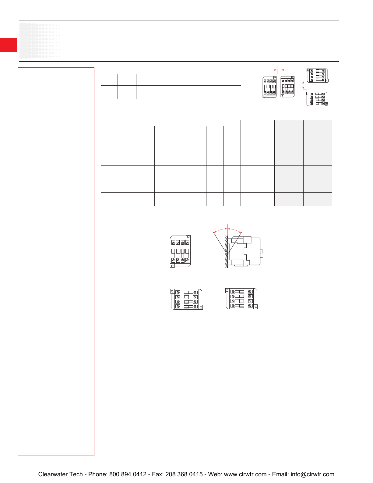
Mounting Distance – for coil operating limits U
A B
mm mm °C Operating cycles/h
2 20 ≤ 20 1200
5 20 ≤ 55 1200
Ambient temp.
Max. switching frequency
min. - Uc max.
c
Add-on accessories
Contactors Max. number of auxiliary contact blocks
CA5-10 CA5-01 CA5-40 CA5-31 CA5-22 CA5-04 TP - A unit marker
pos. 1, 3 or 4
TAL - –30 - 00
TAL - –30 - 10 4 2 1 1 1 – – VE5-1 BA5-50
TAL - –40 - 00
pos. 1, 3 or 4
TAL - –30 - 01 4 1 1 1 – – – VE5-1 BA5-50
pos. 1, 3 or 4
TAL - –22 - 00 4 – 1 – – – – VE5-1 BA5-50
pos. 1 ±30°
all types
TAL all positions
TAE - 6 6 1 1 1 1 1
Note: Railway (traction) projects on request. Type RT surge suppressors are suitable for TAL and TAE contactors.
Mounting positions:
– – – – – – – VE5-1 BA5-50
30°
30°
Timer Interlock Label
VE5-2 1 BA5-50
ABB
Pos. 1
Pos. 3
Pos. 1 ± 30°
ABB
ABB
Pos. 4
1 Only valid for TAE 50-30-00 and TAE 75-30-00.
Page 2
AL... and TAL... Contactors
Technical Data
Connecting Characteristics
Contactor types: AL... 9 12 16 26 30 40
TAL... 9 12 16 26 30 40
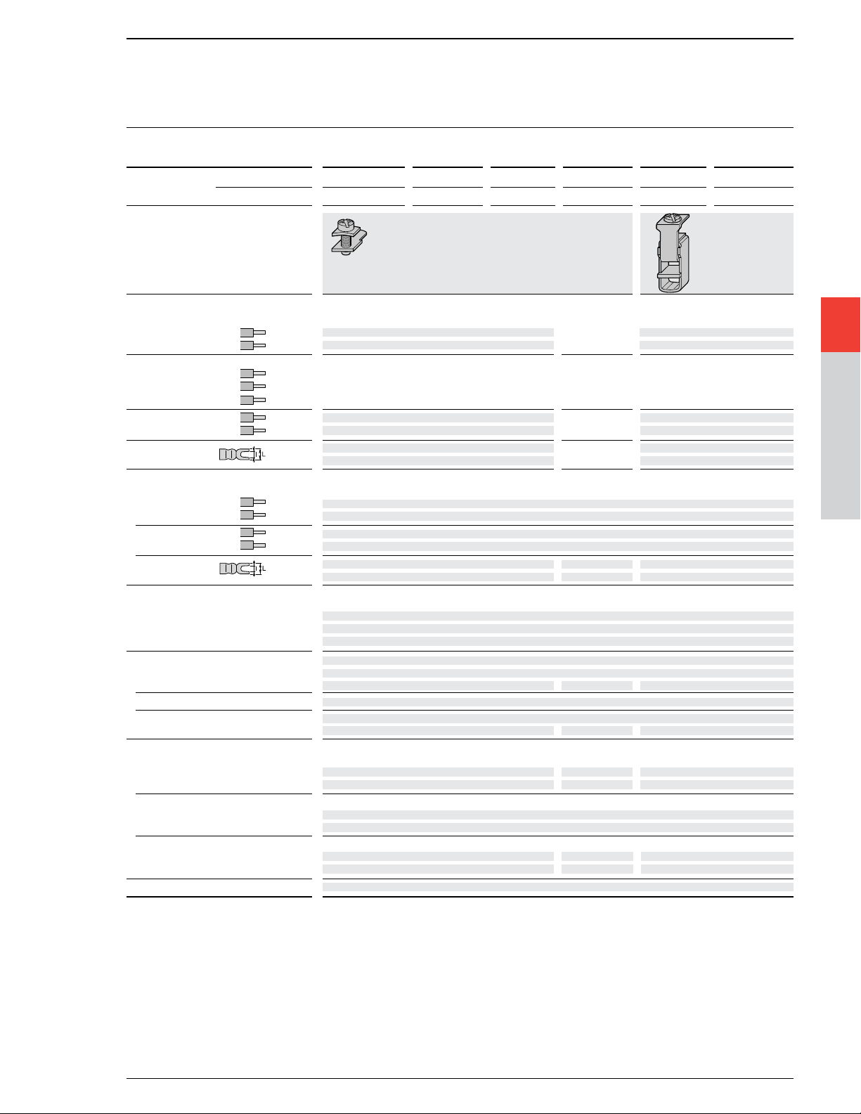
Main terminals
with cable clamp with double
connector
Connecting capacity (min. ... max.)
Main conductors (poles)
Rigid:solid (≤ 4 mm
stranded (≥ 6 mm2)
Rigid with connector
single for Cu cable AWG
single for Al/Cu cable AWG – – – – – –
double for Al/Cu cable AWG – – – – – –
Flexible
with cable end
Bars or lugs L
l mm > 3.7 4.2 –
Auxiliary conductors
(built-in auxiliary terminals + coil terminals)
Rigid solid
Flexible with cable end
Lugs L
l mm > 3.7 (1) 3.7
Degree of protection acc. to IEC 60947-1 / Protection against direct contact acc. to VDE 0106 - Part. 100
EN 60947-1 and IEC 60529 / EN 60529
– Main terminals IP 20
– Coil terminals IP 20
– Built-in auxiliary terminals IP 20
Screw terminals (delivered in open position, screws of unused terminals must be tightened)
Main terminals (+,-) pozidriv 2 screws
Coil terminals M 3.5 (+,-) pozidriv 2 screws with cable clamp
Built-in auxiliary terminals (+,-) pozidriv 2 screws with cable clamp
M3.5 M4 M3.5
Tightening torque
Main pole terminals
– recommended Nm / lb.in 1.00 / 9 1.7 / 15 2.30 / 20
– max.
Coil terminals
– recommended Nm / lb.in 1.00 / 9
– max. Nm 1.20
Built-in auxiliary terminals
– recommended Nm / lb.in 1.00 / 9 1.70 / 15 1.00 / 9
– max.
Terminal marking and positioning contact ABB
2
)
Nm 1.20 2.2 2.60
Nm 1.20 2.20 1.20
1 x AWG
}
18 ... 10 12 ... 8 12 ... 6
2 x AWG 18 ... 10 12 ... 8 12 ... 6
– – – – –
1 x AWG
18 ... 14 12 ... 8
2 x AWG
18 ... 14 12 ... 8
mm ≤ 7.7 10 –
1 x AWG
18 ... 10
2 x AWG
18 ... 10
1 x AWG 18 ... 14
2 x AWG
18 ... 14
mm ≤ 7.7 (1) 8
M3.5 M4 M5
14 ... 8
14 ... 8
–
2 x (5.6 x 6.5 mm)
2
Technical Data
Technical Data
(1) L ≤ 8 and l ≥ 3.7 for coil terminal
Low Voltage Products 2/37
AC 1100
_
L ≤ 10 and l > 4.2 for built-in auxiliary terminals.
Page 3

b2
A
A
b1
C2
C1
E0202D1
ABB
A..., AF..., Contactors
b2
A
A
b1
C2
C1
E0202D1
ABB
Technical Data
General Technical Data
Contactor types: A..., 9 12 16 26 30 40 45 50 63 75 95 110
AF... – – – – – – 45 50 63 75 95 110
Rated insulation voltage Ui
according to IEC 60947-4-1 V 1000
according to UL/CSA
Rated impulse withstand voltage U
Standards Devices complying with international standards IEC 60947-1 / 60947-4-1
and European standards EN 60947-1 / 60947-4-1
Certifications - Approvals UL, CSA, CCC
Air temperature close to contactor ☞ "Conditions for use" page 2/30, for control voltage limits and authorized mounting positions
– fitted with thermal O/L relay °C -25 to +55
– without thermal O/L relay °C -40 to +70
– for storage °C -60 to +80 -40 to +70
Climatic withstand acc. to IEC 60068-2-30 and 60068-2-11 - UTE C 63-100 specification II
Operating altitude m < 3000
Shock withstand
acc. IEC 60068-2-27 and EN 60068-2-27
Mounting position 1 (
page 2/30) 1/2 sinusoidal shock for 11 ms: no change in contact position
☞
Shock direction Making position Breaking position
A 20 g 20 g
B1 10 g 5 g
B2 15 g
C1 20 g 20 g
C2 20 g 20 g
(1) (3 g for AF 45-22, AF 75-22
kV 8
imp.
V 600
(2) (10 g for AF 45-22, AF 75-22
(1)
(2) 15 g (2)
mounting
acc. to IEC 68-2-30
Not valid for DIN-rail
General Technical Data for AL..., TAL... Contactors
Contactor types: AL... , TAL... 9 12 16 26 30 40
Rated insulation voltage Ui
according to
according to UL/CSA
Rated impulse withstand voltage U
Standards Devices complying with international standards IEC 60947-1 / 60947-4-1
and European standards EN 60947-1 / 60947-4-1
Certifications - Approvals UL, CSA
Air temperature close to contactor ☞ "Conditions for use" page 2/36, for control voltage limits and authorized mounting positions
– fitted with thermal O/L relay
– without thermal O/L relay
– for storage °C -60 to +80
Climatic withstand acc. to IEC 60068-2-30 and 60068-2-11 - UTE C 63-100 specification II
Operating altitude m < 3000
Shock withstand
acc. IEC 60068-2-27 and EN 60068-2-27
Mounting position 1 (
Shock direction Making position Breaking position
A 20 g 10 g
B1 15 g 5 g
B2 10 g 15 g
C1 20 g 8 g
C2 14 g
IEC 60947-4-1
V 1000
V 600
page 2/36) 1/2 sinusoidal shock for 11 ms: no change in contact position
☞
kV 8
imp.
°C -25 to +55
°C -40 to +70
8 g
2/24 Low Voltage Products
AC 1100
 Loading...