

Page 1
Low Volta ge D ri ves
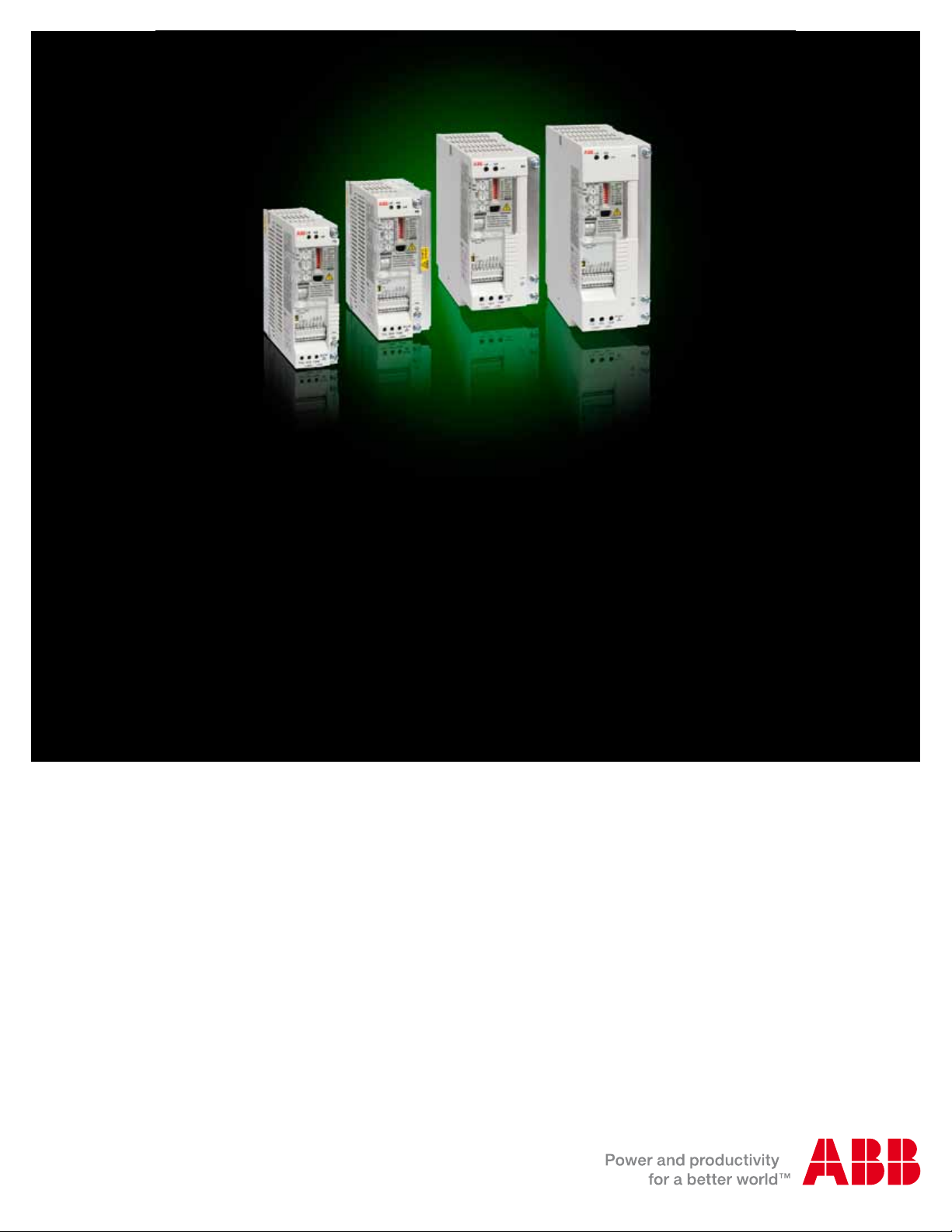
ABB component drives
ACS55, 0.25 to 3 hp (0.18 to 2.2 kW)
Catalog
Page 2

ABB Component Drive
What is the ACS55 customer value?
− Reduces panel size
− Reduces commissioning, installation and energy costs
− Replaces contactors and starters
The ABB ACS55 Component Drive continues in the tradition of
ABB AC Drives being simple to buy, install, configure and use,
saving considerable time. The ACS55 can easily be integrated
into existing or smaller panels, replacing contactors and motor
starters due to its compact size as well as new installations
or wherever energy savings of small AC induction motors is
desired.
Where can it be used?
The ABB ACS55 Component Drive can be used in a wide range
of industries. Typical applications include pumps and fans as
well as constant torque applications such as material handling.
The ABB ACS55 Component Drive is ideal for those situations
where a low cost, easy to install and easy to operate product is
needed.
Additional applications include:
− Heat Exchangers
− Packaging Machines
− X-ray Screening Systems
− Exercise Training & SPA Equipment
− Ovens
− Powered Roof-Ventilators
− Food & Beverage Machines
ABB ACS55 Component Drive Promises
− Easy and descriptive interface
− Compact size and slim
− DIN rail mounting
− Quiet motor operation
Highlights
− Power range 0.25 to 3 Hp
− Protected Chassis (IP 20)
− Silent Motor
− Optimized switching frequency up to 16kHz
− Suitable for domestic environment
− Fast and safe drive configuration with DriveConfig kit
− Ideal for DIN-rail mounting
− RoHS
− Coated boards
What are the ACS55's main features and benefits supporting customer value?
Feature Note Benefit
Descriptive Interface All inverter parameter settings are made with DIP switches and
potentiometers
Compact size and thin shape up to 0.5 Hp 1.77" width, 1 Hp 2.66" width Less space required for instal lation
DriveConfig kit New drive configuration tool for volume manufacturing Fast and safe configuration of unpowered driv es
Removable mounting clip Removable clip allows DIN-rail and wall mounting from back and
side of the unit
Automatic switching frequency Increases switchi ng frequency automatically, when drive te mpe-
rature is decreased
EMC 1st Environment b uilt-in EMC filter unit is a vailable Low EMC emissions
2 A CS55 Technical Ca talog
Faster set-up
Easier configuration
Easier set-up for new users
Flexible and easy mounting
Provides lowest p ossible noise without derati ng of
the drive
Page 3

Ratings, Types and Voltages
Output Current
Type Code
1-phase supply voltage 110 to 120V, +10/-15%, 3-phase outp ut 200 to 240V
ACS55-01N-01A4-1 A 0.25 1.4 2.1 6.4 6.69 5.77 1.77 5.04 1.5
ACS55-01N-02A2-1 A 0.5 2.2 3.3 9.5 6.69 5.77 1.77 5.04 1.5
1-phase supply voltage 200 to 240V, +10/-15%, 3-phase outp ut 200 to 240V
ACS55-01N-01A4-2 A 0.25 1.4 2.1 4.4 6.69 5.77 1.77 5.04 1.5
ACS55-01N-02A2-2 A 0.5 2.2 3.3 6.9 6.69 5.77 1.77 5.04 1.5
ACS55-01N-04A3-2 B 1.0 4.3 6.5 10.8 6.69 5.77 2.66 5.04 2.4
ACS55-01N-07A6-2 C 2.0 7.6 11.4 18.2 7.6 6.7 2.8 6.3 2.4
ACS55-01N-09A8-2 C 3.0 9.8 14.7 22 7.6 6.7 2.8 6.3 2.4
Type Code
1-phase supply voltage 110 to 120V, 3-phase output 200 to 240V (Built-in EMC filter)
ACS55-01E-01A4-1 A 0.25 1.4 2.1 6.4 6.7 5.7 1.77 5.0 1.4
ACS55-01E-02A2-1 A 0.5 2.2 3.3 9.5 6.7 5.7 1.77 5.0 1.5
1-phase supply voltage 200 to 240V, 3-phase output 200 to 240V (Built-in EMC filter)
ACS55-01E-01A4-2 A 0.25 1.4 2.1 4.4 6.7 5.7 1.77 5.0 1.4
ACS55-01E-02A2-2 A 0.5 2.2 3.3 6.9 6.7 5.7 1.77 5.0 1.5
ACS55-01E-04A3-2 B 1.0 4.3 6.5 10.8 6.7 5.7 2.6 5.0 1.5
ACS55-01E-07A6-2 D 2.0 7.6 11.4 18.2 8.9 8.0 2.7 6.2 2.4
ACS55-01E-09A8-2 D 3.0 9.8 14.7 22 8.9 8.0 2.7 6.2 2.4
Frame
Size
Frame
Size
P
Hp
P
Hp
N
N
Nominal
I
2N
A
Output Current
Nominal
I
2N
A
Maximum
A H1 H2 W D
Maximum
A H1 H2 W D
Input
Current
A
Input
Current
A
Dimensions
inches
Dimensions
inches
Weight
lbs
Weight
lbs
PN = Nominal Power
I2N = Nominal Current
H1
H2
D
Supply terminals L, N (R, S)
Conguration switches
Control potentiometers
DriveCong kit interface
Relay output terminals
Analog input signal selector (U/I)
Control terminal
Motor terminals T1, T2, T3 (U,V,W)
H1= Height with mounting clip
H2 = Height without mounting clip
W
W = Width
D = Depth
ACS5 5 Techn ical Catal og 3
Page 4

Options
RFDT-01 or RFDT-02 DriveConfig Kit
The DriveConfig kit is a PC tool for volume configuration and
control of ACS55 drives. The kit enables parameter setting and
software updating without the need for a power connection. The
drives can even remain in their delivery boxes during configuration. The DriveConfig kit features on-line drive control and monitoring of up to four signals simultaneously. Together with ACS55
drives, the DriveConfig kit brings additional value to processes
by saving time and ensuring safety.
DriveConfig kit includes:
− Hardware and cables
− PC software
− User’s manual in English (hardcopy and PDF)
− Battery charger
− Serial port (RFDT-01) / USB adapter (RFDT-02)
DriveConfig kit requirements:
− PC with Microsoft Windows 2000/XP operating system
− Free serial or USB port from the PC
Potentiometer
The ACS50-POT potentiometer is an option for ACS55 drives.
Two switches are included in addition to the potentiometer for
drive control; start / stop and forward / reverse. The ACS50POT potentiometer does not require any external power source.
Type Code - ACS55-POT
ACS55
COM
COM
SPEED/AI
+10 V
jog
reverse
start/
stop
+12 V
START
REV
JOG
SCR
4 A CS55 Technical Ca talog
10
11
RO1
RO2
fault or run
Page 5

Technical Specification
Mains Connection
Power range 0.25 to 3.0Hp (0.18 to 2.2kW)
Input Voltag e
Frequency 48 to 63Hz
Motor Connection
Output Volta ge
Frequency 0 to 120/130Hz
Overload Capacity 150% (60 s)
Switching Frequen cy
Acceleration Time 0.1 to 30 s
Deceleration Time 0.1 to 30 s
Environmental Lim its
Ambient Temperature
Altitude
Relative Humidity
Protection Class IP20, Protected Chassis
Contamination Levels
Sinusoidal Vibration
1-phase, 110 to 120V and 200 to 240V, +10/-
15%
3-phase, from 0 t o U
(for 100/115V fro m 0 to 230V)
5kHz, adjustable up to 16kHz with automatic
switching frequen cy reduction
-4°F (-20°C) to 104°F (40°C) No Frost Allowed
122°F (50°C) with derating to 85% nominal
output current
0 to 3280 ft (1000 m) with derating of 1% per
320 ft (100 m) over 3280 ft (1000 m) to 6560 ft
(2000 m)
Less than 95%
(without condensation)
No conductive dust allowed,
corrosive liquids or gasses
(IEC60721-3-3)
Chemical gases: Class 3C2
Solid particles: Class 3S2
Frequency range: 5 - 150 Hz
Constant Peak Acceleration: 1g
ISTA 2A
SUPPLY
Control Connectio ns
One analog input
Voltage Sign al
Current Signal
Potentiometer
reference value
Response T ime
Resolution
Accuracy
Three Digital Inp uts
Auxiliary Power
Supply
Input Impedance
Response T ime
One Relay Output
Switching Voltage
Maximum Continuous
Current
Product Complianc e
Low Voltage Directive 73/ 23/EEC with supplements
EMC Directive 89/ 336/EEC with supplements
Quality assurance system ISO 9001 and Environ mental
system ISO 140001
CE, UL, cUL, C-T ick, and GOS T-R approvals
EMC standards in general
EN 61800-3/A11
(2000),
product standard
1st environment,
unrestricted
distribution
1st environment,
restricted distri bution
2nd environment,
unrestricted
distribution
2nd environment, restric-
ted distribution
0 (2) to 10V, 200kΩ single-end ed
0 (4) to 20 mA, 100Ω single-ended
10V ±2% max 10mA, 1kΩ ≤ R ≤10kΩ
≤ 60 ms
0.1%
±2%
12VDC to 24VDC
12VDC max 30mA
1.5kΩ
≤ 9 ms
12 to 250VAC or max 30VDC / 0.5A
2A
EN 55011, product fami-
EN61800-3 (2004),
product standard
Category C1
Category C2
Category C3
Category C4 Not applicable
ly standard for i ndustrial,
scientific and medical
(ISM) equipment
Group 1
Class B
Group 1
Class A
Group 2
Class A
ACS5 5 Techn ical Catal og 5
Page 6

Contact us
ABB Inc
Low Voltage Drives
16250 W. Glendale Drive
New Berlin, WI 53151 USA
Phone: (800) 752-0696
Fax: (262) 785-0397
Web: www.abb.us/drives
ABB Inc
Low Voltage Drives- Canada
2117, 32nd Avenue
Lachine, QC H8T 3J1
Tel: (514) 420-3111 ext: 3505
Fax: (514) 420-3138
Web: www.abb.com
ACS55- PHTC01U-EN REV C 02/28/2010 Specifications s ubject to change without no tice.
 Loading...