

Page 1
M25102xC
M25102xA-xM25102xPx.
M25102xK-x.
M25102xCR.
5102xDN
5101xPx
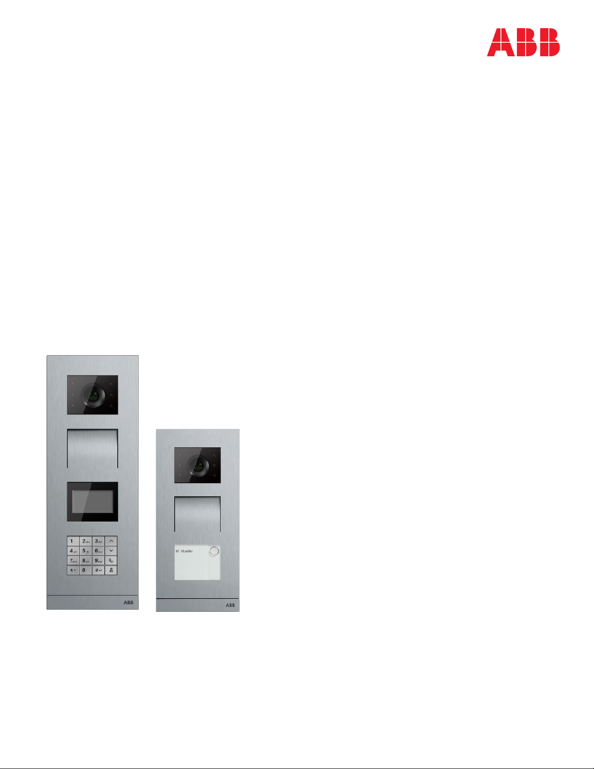
Outdoor station
Pos: 2 /DinA4 - Anleitungen Online/Inhalt/KNX/DoorEntry/83220-AP-xxx/Titelblatt - 83220-AP-xxx - ABB @ 19\mod_1323249806476_15. docx @ 11108 4 @ @ 1
—
VER: 1.3 | 02.20.2017
ABB Welcome®
Page 2
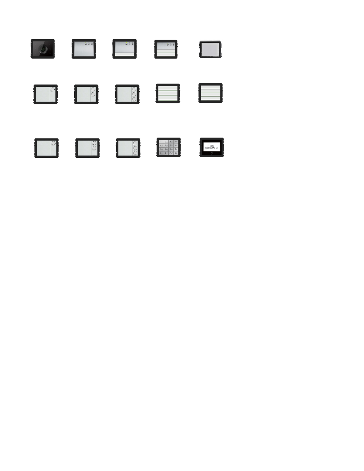
Camera module
Audio mod ule
Audio mod ule
Audio mod ule
Nameplate module
Round pushbutton
Round pushbutton
Round pushbutton
Pushbutto n
Pushbutto n
Round pushbutton
1 button, with NFC/IC
Round pushbutton
2 button, with
Round pushbutton
Keypad (3 versions)
Stainless steel
Aluminum
White
Display with ID
Display with IC
Module family
1 button
2 button
NFC/IC
3 button
3 button, with
NFC/IC
3/6 button
4/8 button
Page 3

ABB Welcome
— 3 —
®
1 Safety....................................................................................................... 5
2 Intended use ............................................................................................ 5
3 Environment ............................................................................................. 5
3.1 ABB devices ............................................................................. 5
4 Terminal description ................................................................................. 6
4.1 Audio module ........................................................................... 6
4.1.1 Lock connected with terminals 3 and 4 .....................................12
4.2 Camera module .......................................................................13
4.2.1 Analog camera connected with terminal 1.................................14
4.2.2 Detached camera connection ...................................................15
4.3 Round pushbutton module .......................................................16
4.4 Pushbutton module ..................................................................18
4.5 Keypad module .......................................................................20
4.6 Display and card reader module ...............................................22
4.7 Nameplate module ..................................................................25
5 Operation ................................................................................................26
5.1 Pushbutton outdoor station ......................................................26
5.1.1 Addressing ..............................................................................26
5.1.2 Setting the language for the voice messages
(if the audio module has a speech synthesis function) ...............32
5.2 Pushbutton outdoor station with display module ........................34
5.3 Pushbutton outdoor station with keypad module .......................36
5.4 Round pushbutton outdoor station with IC/NFC ........................38
5.5 Keypad outdoor station ............................................................42
5.5.1 Call a resident (3 types) ...........................................................42
5.5.2 Call the guard unit ...................................................................44
5.5.3 If an indoor station is in “leave home mode” ..............................44
5.5.4 If a guard unit is in "intercept mode" .........................................45
5.5.5 System settings .......................................................................46
5.6 Keypad outdoor station without display
(camera + audio + keypad) ......................................................56
5.6.1 Calling a resident by inputting physical address ........................56
5.6.2 Call guard unit .........................................................................56
5.6.3 System settings .......................................................................56
6 Advanced configuration............................................................................58
7 Technical data .........................................................................................59
8 Mounting and installation .........................................................................60
8.1 Requirements for the electrician ...............................................60
8.2 General installation instructions ................................................61
8.3 Mounting .................................................................................62
Page 4

ABB Welcome
— 4 —
®
Page 5

ABB Welcome
— 5 —
Warning
Electric voltage!
Direct or indirect contact with live components can cause dangerous
currents to flow through the body, which may result in electric shock,
burns or even death.
- Always disconnect the main power supply prior to installation and/or
disassem bly.
- Work on the 110 V - 240 V supply system must be performed only
by qualified personnel.
Consider the protection of the environment!
Used electric and electronic devices must not be disposed of with
household waste.
– The device contains valuable raw materials that can be recycled
and should be disposed of at an appropriate recycling facility.
®
1 Safety
2 Intended use
The outdoor station is an integral part of the ABB Welcome door entry system and operates exclusively with components from this system.
The device must only be used with suitable ABB flush-mounted installation sockets and rain hood.
3 Environment
3.1 ABB devices
All packaging materials and devices from ABB bear the markings and test seals for proper disposal. Always dispose of the packing
materials, electric devices and their components via authorized collection facility or disposal company.
Page 6
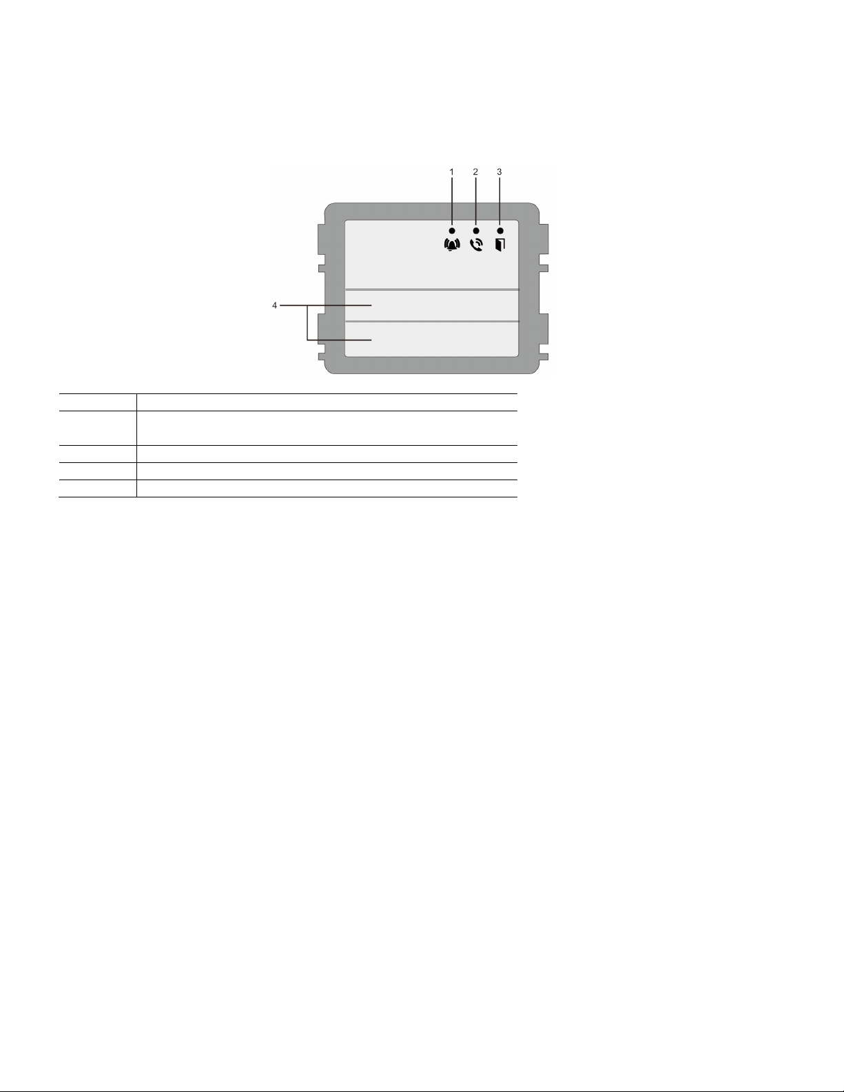
ABB Welcome
— 6 —
No.
Function
1
LED flashes slowly, indicating a call has been established
LED flashes fast, indicating that the system is busy
2
LED illuminates, indicating possible communication
3
LED illuminates, indicating the door is unlocked
4
Call pushbuttons
®
4 Terminal description
4.1 Audio module
Page 7
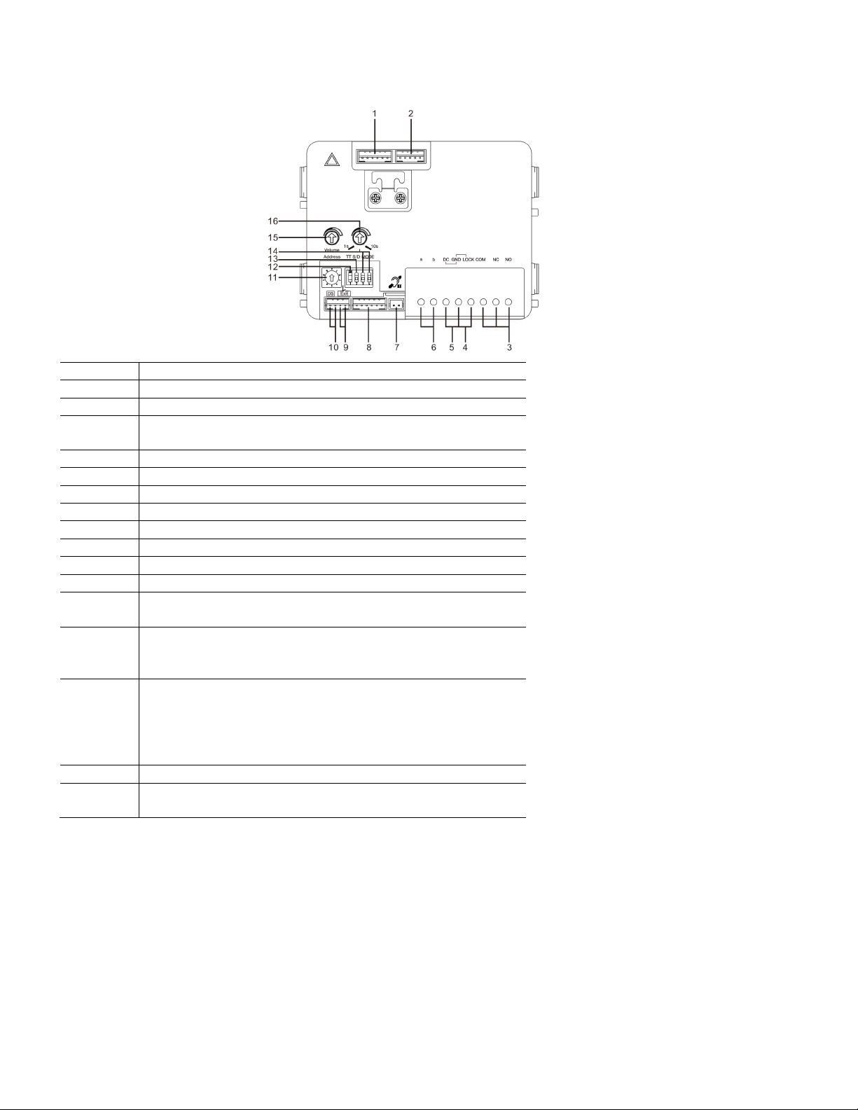
ABB Welcome
— 7 —
No.
Functions
1
Connector for camera module
2
Connector for device software update
3
Plug-in clamps (COM-NC-NO) for floating output, door opener (30 V
AC/DC, 1 A)
4
Plug-in clamps (Lock-GND) for door opener (18 V 4 A, 12 V 250 mA)
5
Plug-in clamps (DC-GND) for additional power supply
6
Plug-in clamps (a-b) for bus connection
7
Connector for induction loop module
8
Connector for next module
9
Connector for exit pushbutton
10
Connector for sensor for monitoring door status
11
Rotary switch for setting the address of OS (1-9)
12
Set feedback tones for pushbuttons and for outdoor station when making
a call: ON or OFF
13
Configure pushbuttons in a single column or double column mode
(ON=double column; OFF=single column)
This only affects the bar pushbutton, not the round pushbutton.
14
Configure functions of the first and second pushbuttons
3->OFF, 4->OFF=call indoor station and call indoor station
3->ON, 4->OFF=switch on lighting and call indoor station
3->OFF, 4->ON=call guard unit and call indoor station
3->ON, 4->ON=switch on lighting and call guard unit
15
Adjust the loudspeaker volume
16
*Adjust the door lock release time, 1-10 s eco nds (available for the
lock connected with the default lock)
®
Page 8
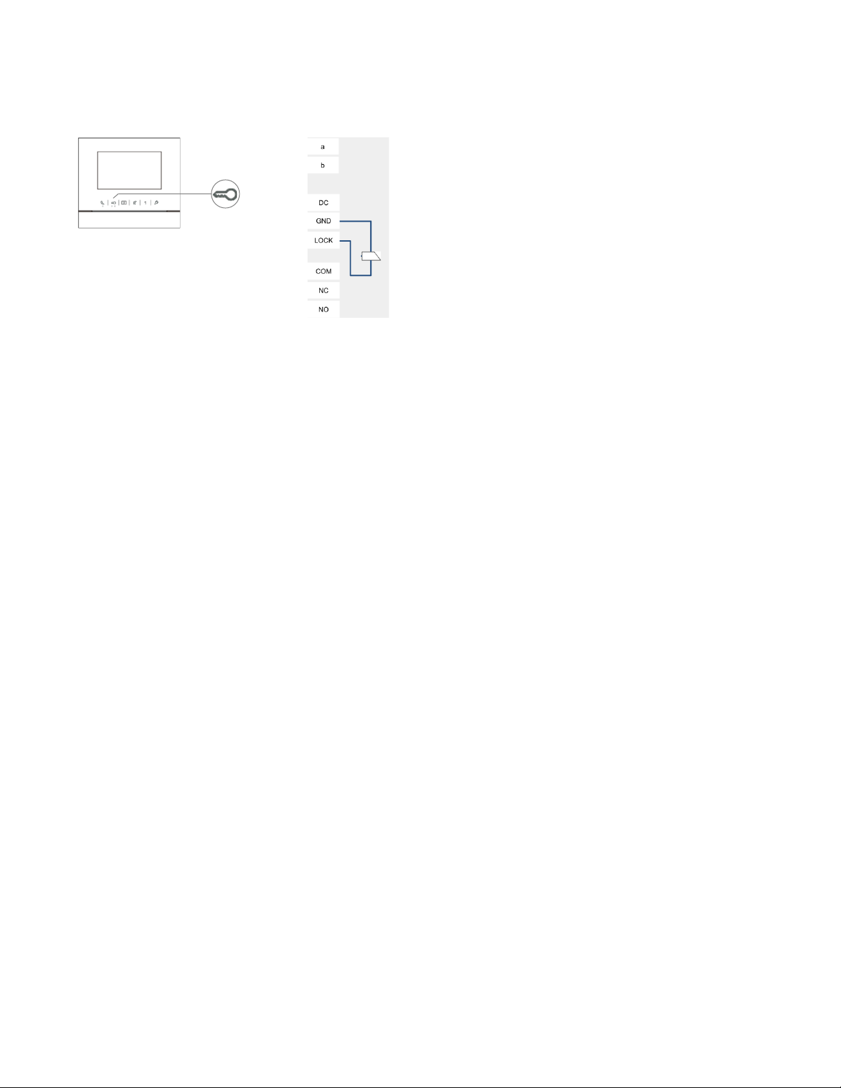
ABB Welcome
— 8 —
®
*Default lock (first lock): Released by “unlock” button of the indoor station. Factory setting
is LOCK-GND.
Page 9
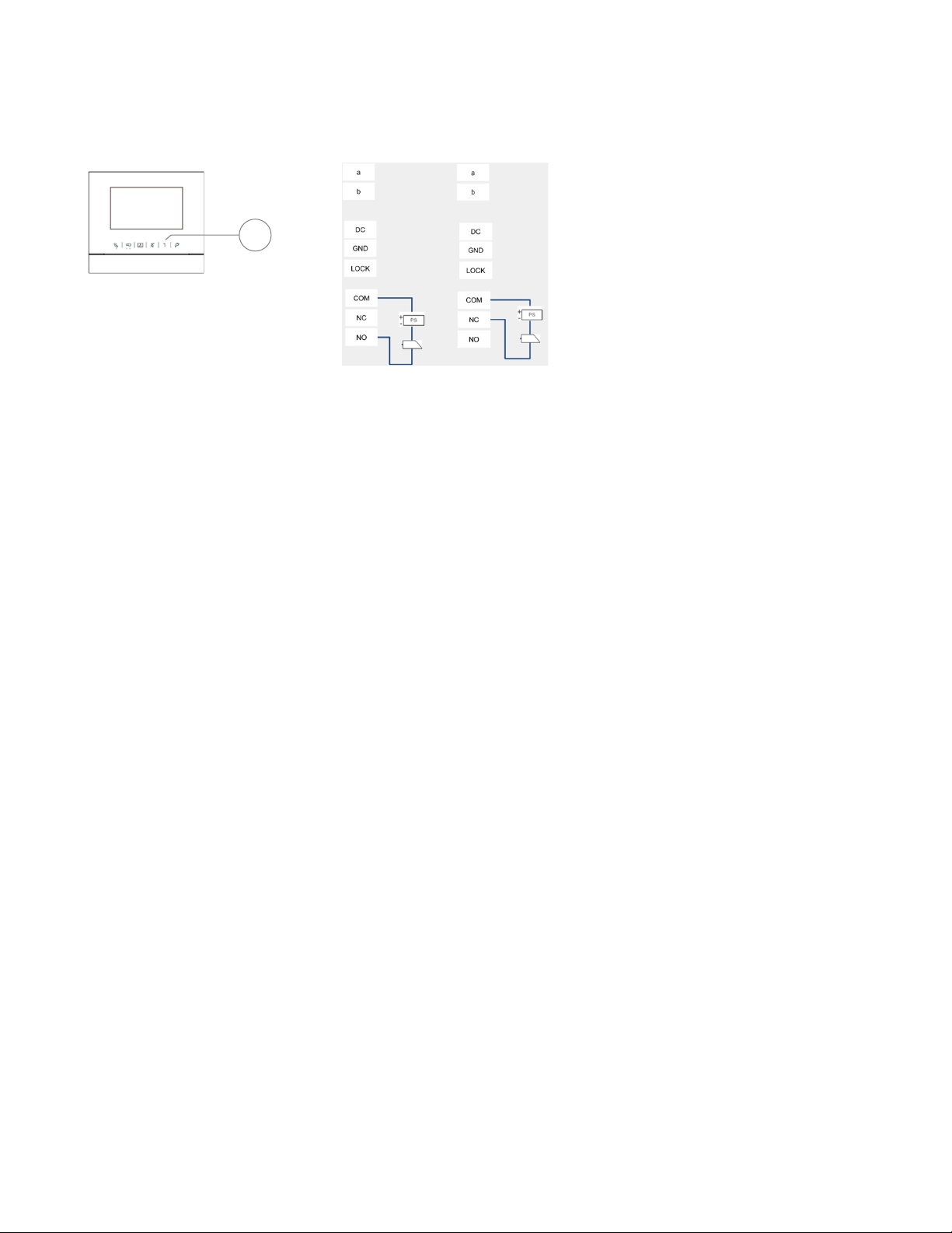
ABB Welcome
— 9 —
1
®
Second lock: Rel eased by programmable button “1” of the indoor station. Factory setting
is COM-NC-NO.
Page 10
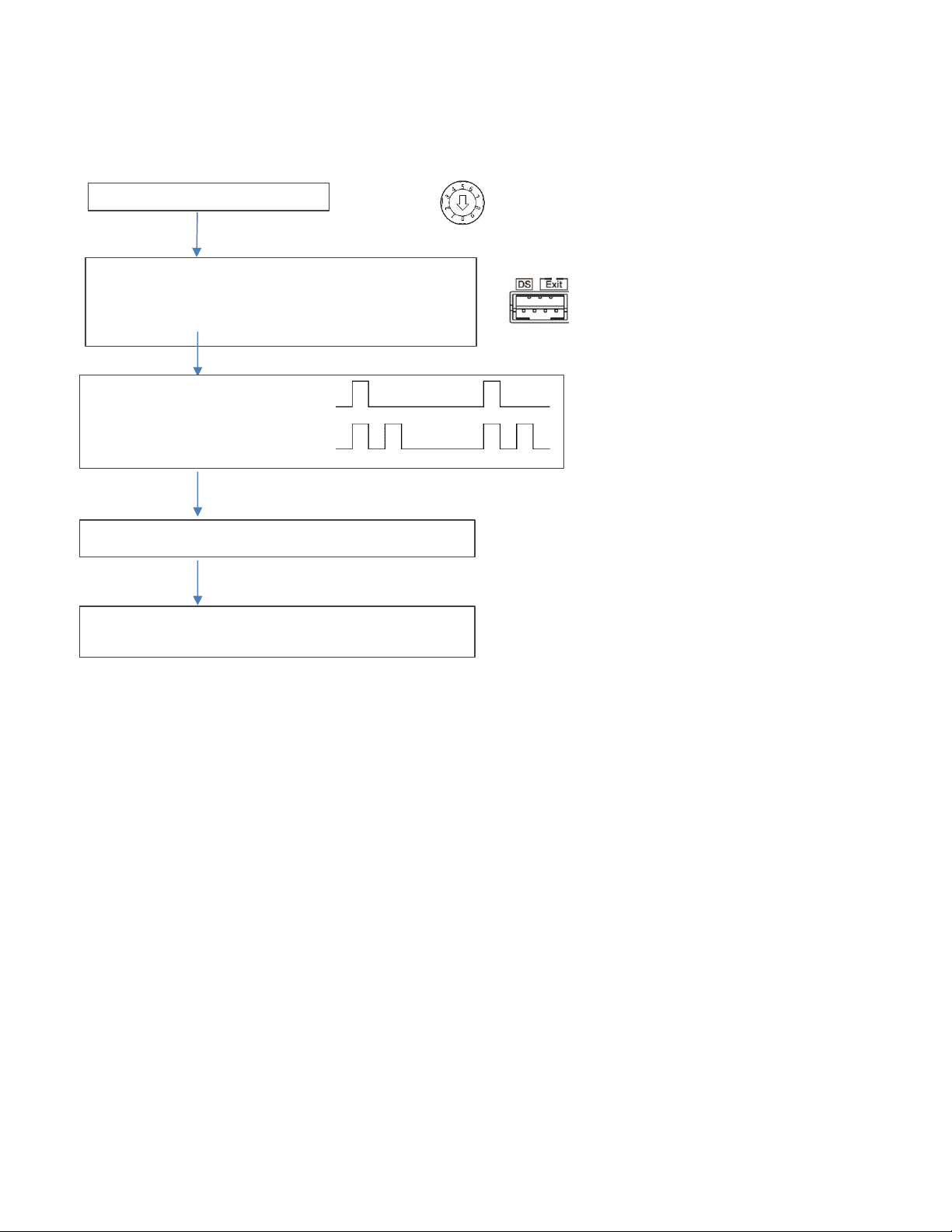
ABB Welcome
— 10 —
Set outdoor station address ="0"
Short circuit the "Exit" two terminals for 3 seconds to enter the
Tones for indication:
Short circuit “Exit” terminal on outdoor station to switch the default lock
30 seconds time available to save the setting and exit the
®
Change default lock
Default lock can be set at either "Lock-GND" or "NO-NC-COM"
1
setting mode
(3 LED flashes green to show the setting mode for aluminum outdoor
station)
(prompt tone “di” for stainless outdo or station)
Lock 1 (LOCK-GND) = default lock
Lock 2 (NC-NO-COM) = default lock
programming mode
Page 11
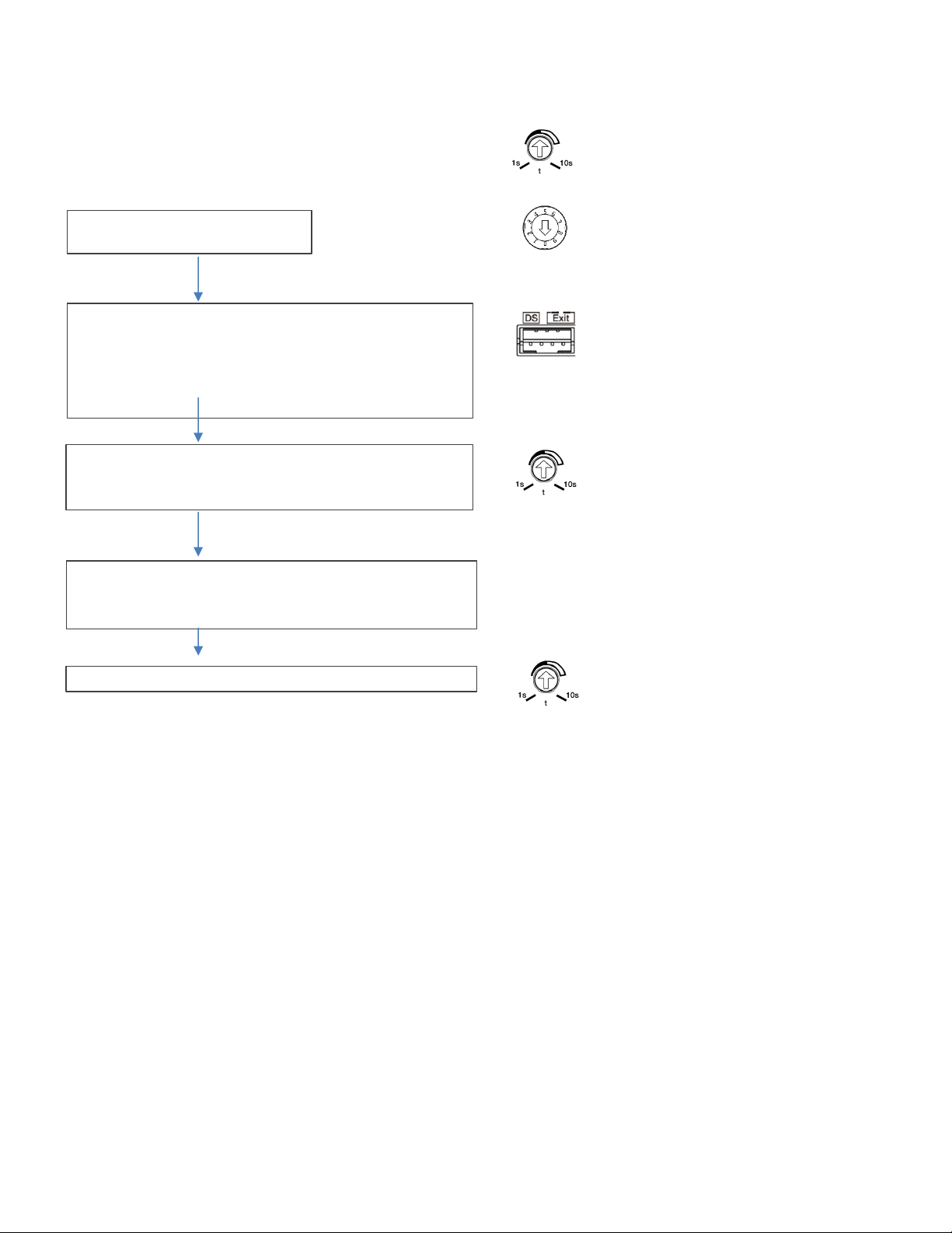
ABB Welcome
— 11 —
Set the lock time of the default lock
Set the lock time of the second lock
Set outdoor station address ="0"
Short circuit the “DS” two terminals for 3 seconds to enter the
Record the time for first lock
30 seconds time available to save the setting and exit the
At last set the time back for 1st-Lock
Reset the time to the original time for first lock
®
Set the time by the potentiometer, from 1-10 seconds
setting mode
(3 LED flashes green to show the setting mode for aluminu m outdoor
station)
(Beep tone sounds for stainless outdoor station)
Then set the time for second-Lock from 1-10 seconds
programming mode
Page 12
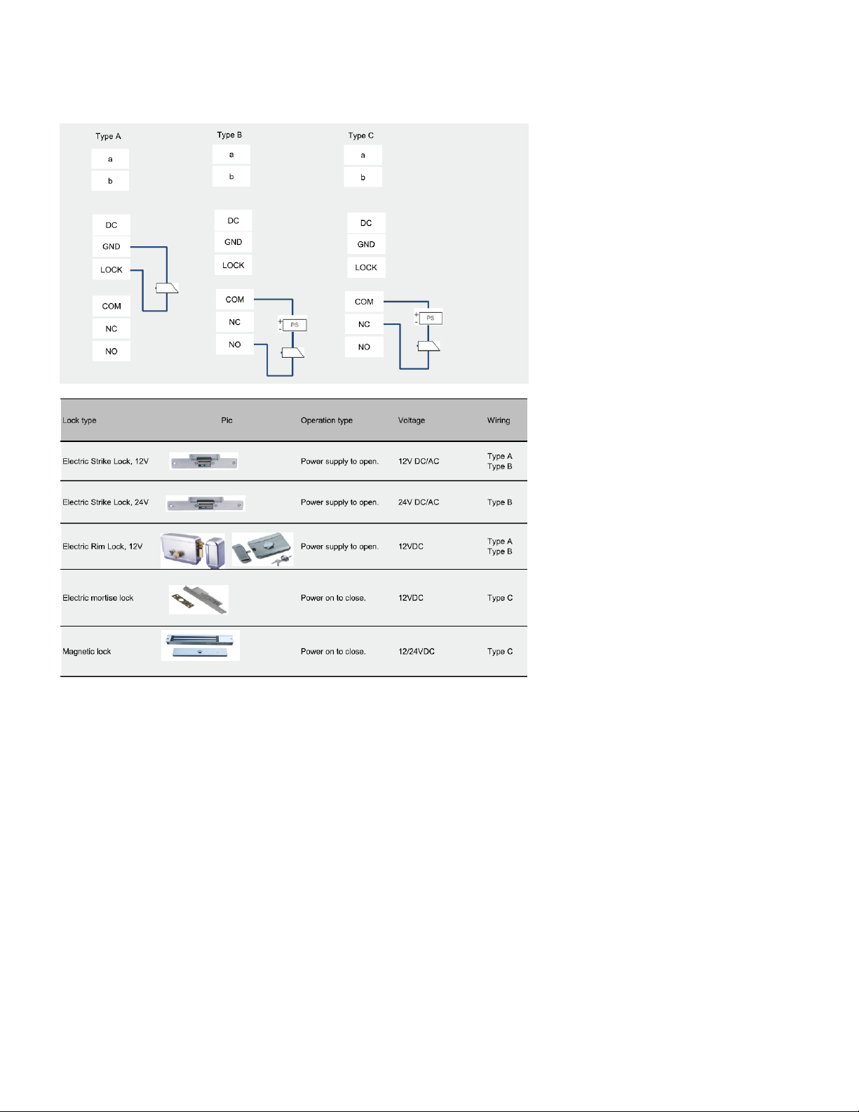
ABB Welcome
— 12 —
®
4.1.1 Lock connected with terminals 3 and 4
Page 13
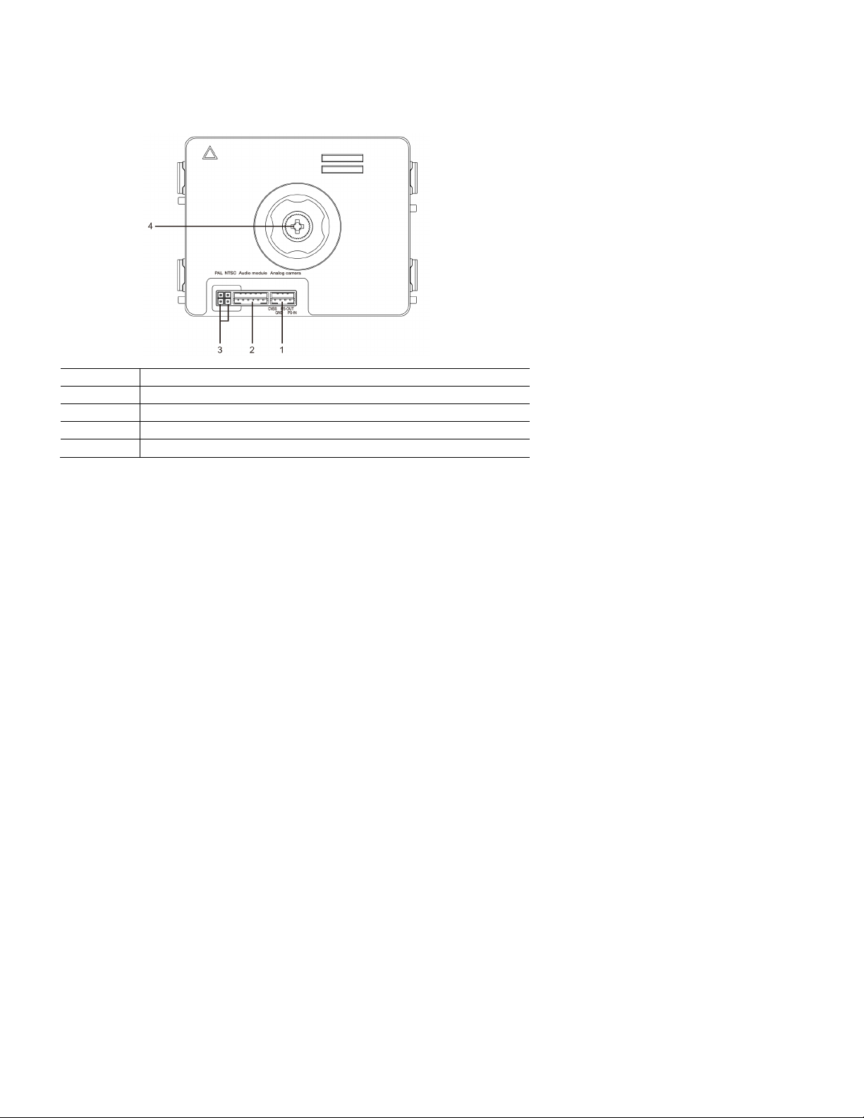
ABB Welcome
— 13 —
No.
Functions
1
Connector for additional analog camera
2
Connector for audio module
3
Jumper for setting the video format: PAL or NTSC
4
Adjust the camera view area
®
4.2 Camera module
Page 14
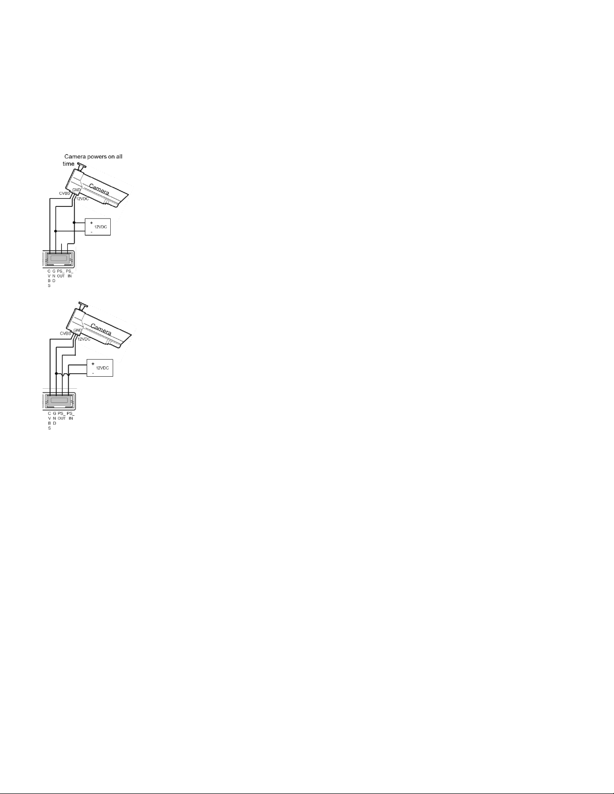
ABB Welcome
— 14 —
®
4.2.1 Analog camera connected with terminal 1
All the cameras with the video output of 1Vp-p 75Ω, CVBS (composit e video broadcast signal) can be connected with the camera m odule.
Generally, the transmission distance from the analog camera to the outdoor station can reach up to 164 ft. by coax cables or about 33 ft. by other
types of cables.
Two types of connections:
Option 1: The analog camera is powered on all the time.
Option 2: The analog camera is powered on only during working hours.
Page 15
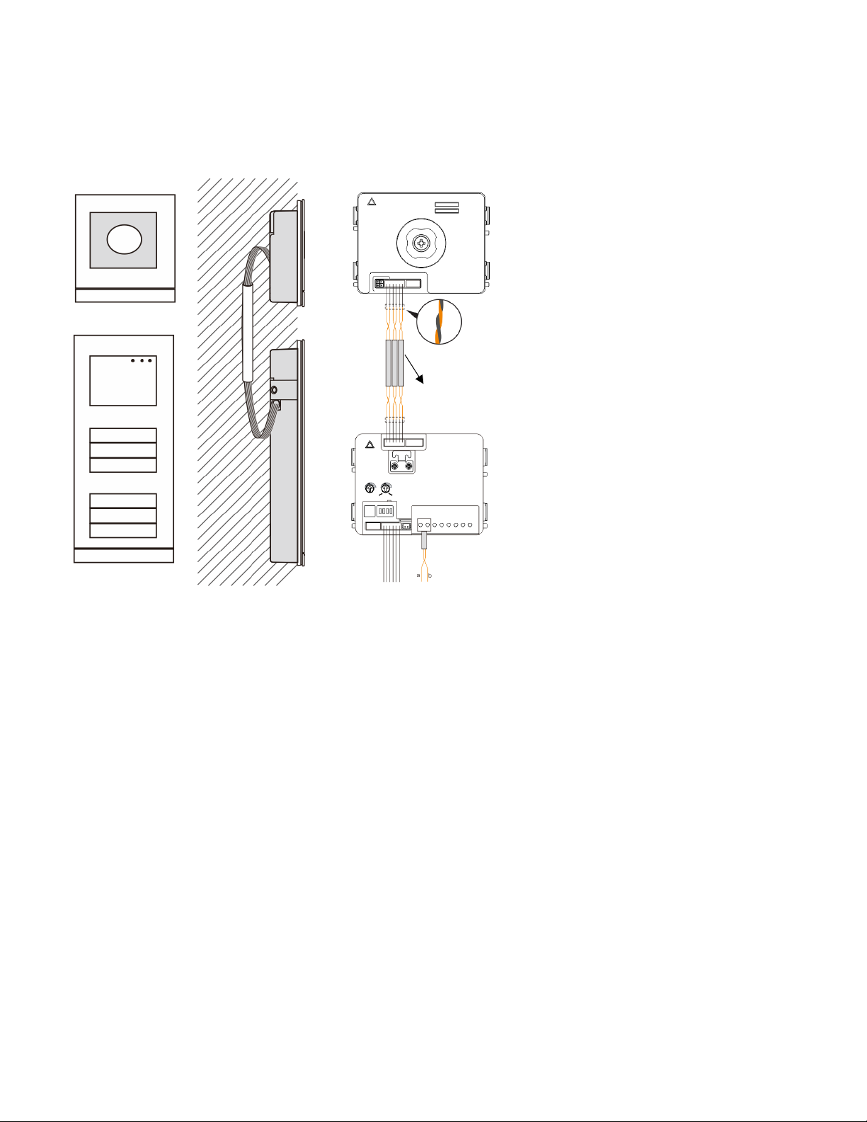
ABB Welcome
— 15 —
3 pairs 2-wire bus
together
Max:10 metres
®
4.2.2 Detached camera connection
Camera module can be used as a detached camera. Wiring is shown below.
Page 16
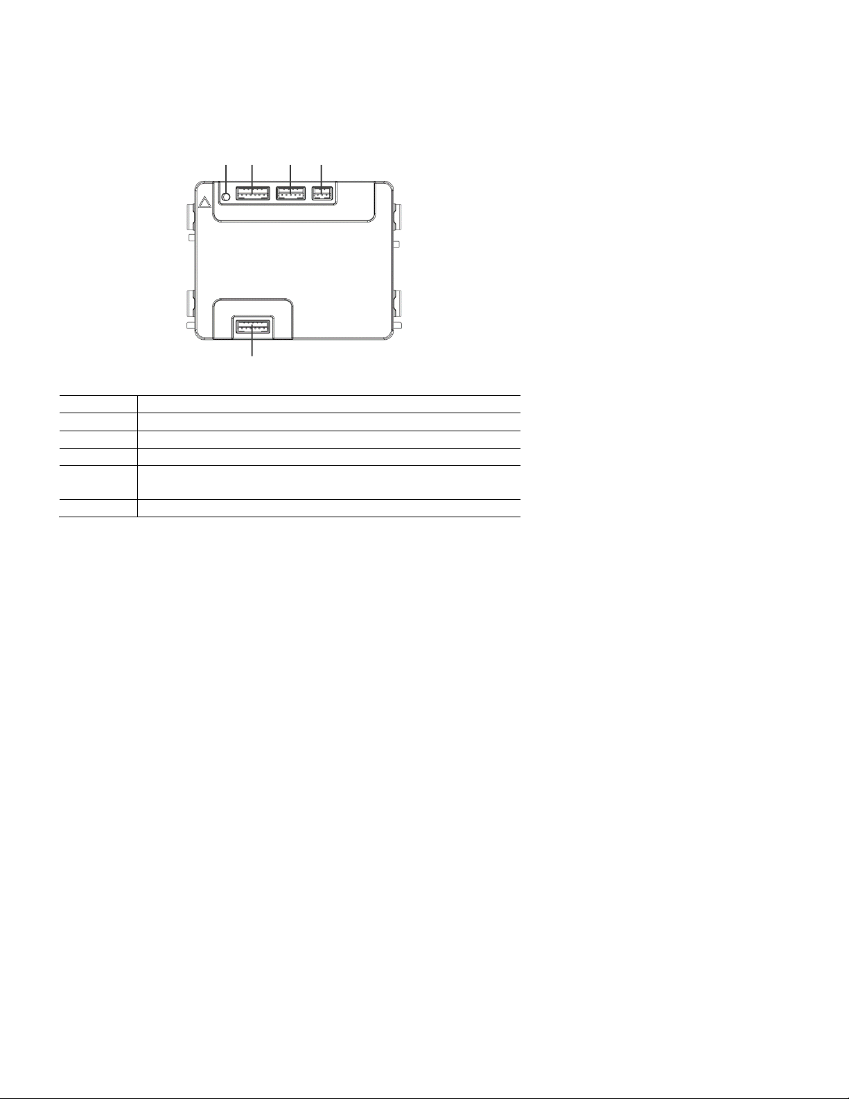
ABB Welcome
— 16 —
No.
Functions
1
Program button
2
Connector for previous module
3
Connector for device software update
4
Connector for Wiegand output
Default format is 26 bits; it can also be extended to 34 bits.
5
Connector for next module
1
2 3 4
5
®
4.3 Round pushbutton module
Page 17
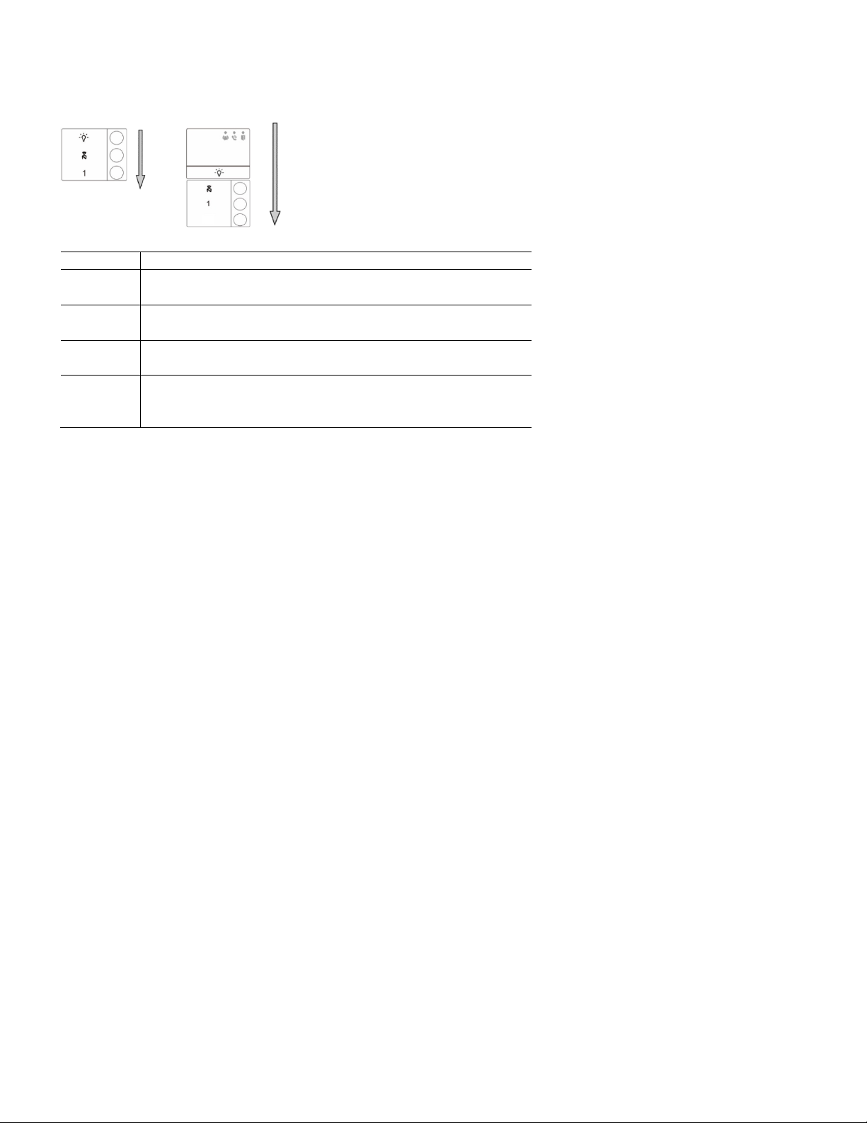
ABB Welcome
— 17 —
No.
Functions
1
Regardless of the structure of the pushbutton module, button numbers are
listed from top to bottom.
2
Lighting switch and call guard unit function is always assigned to the first
and second button, which is set by audio module.
3
User names can be printed by us ing the labeling tool of the ABB Welcome
configuration software.
4
The round pushbutton module with NFC/IC card reader supports the
NFC/IC c ard. A mobile phone with NFC function is acceptable. (“Door
Open” App required.)
2
®
Page 18
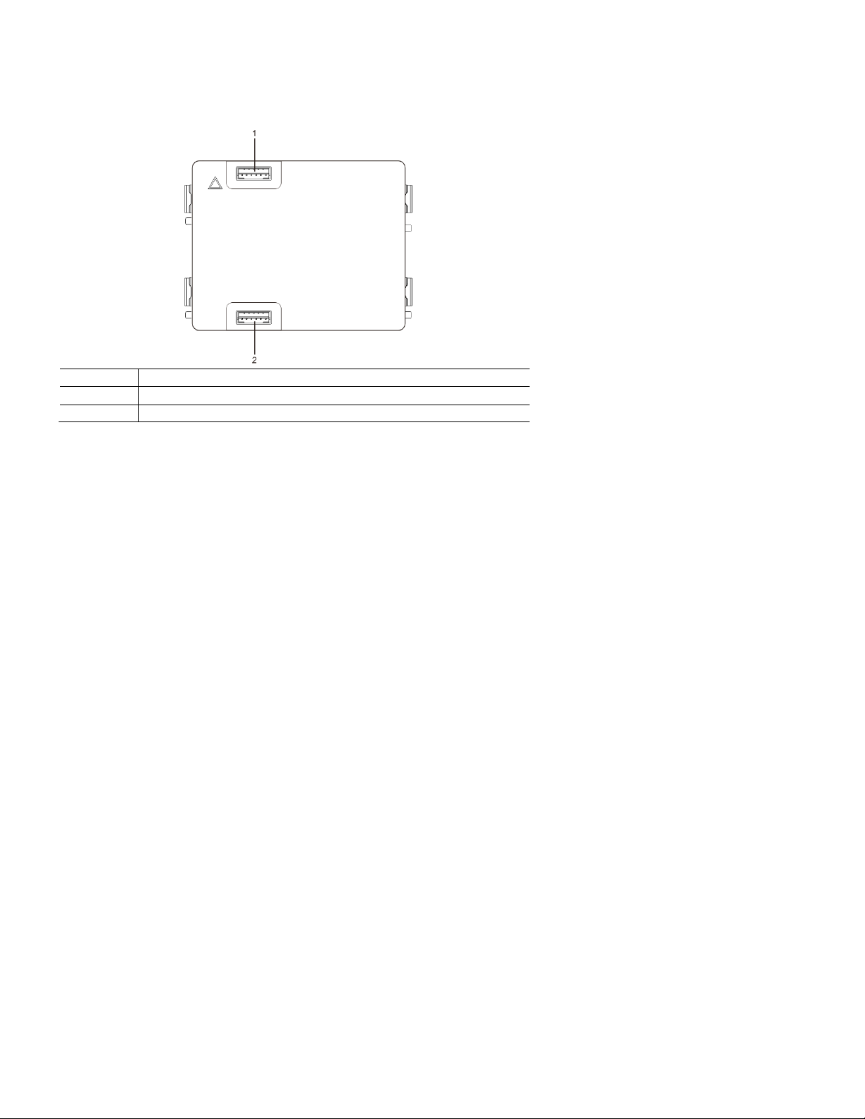
ABB Welcome
— 18 —
No.
Functions
1
Connector for previous module
2
Connector for next module
®
4.4 Pushbutton module
Page 19
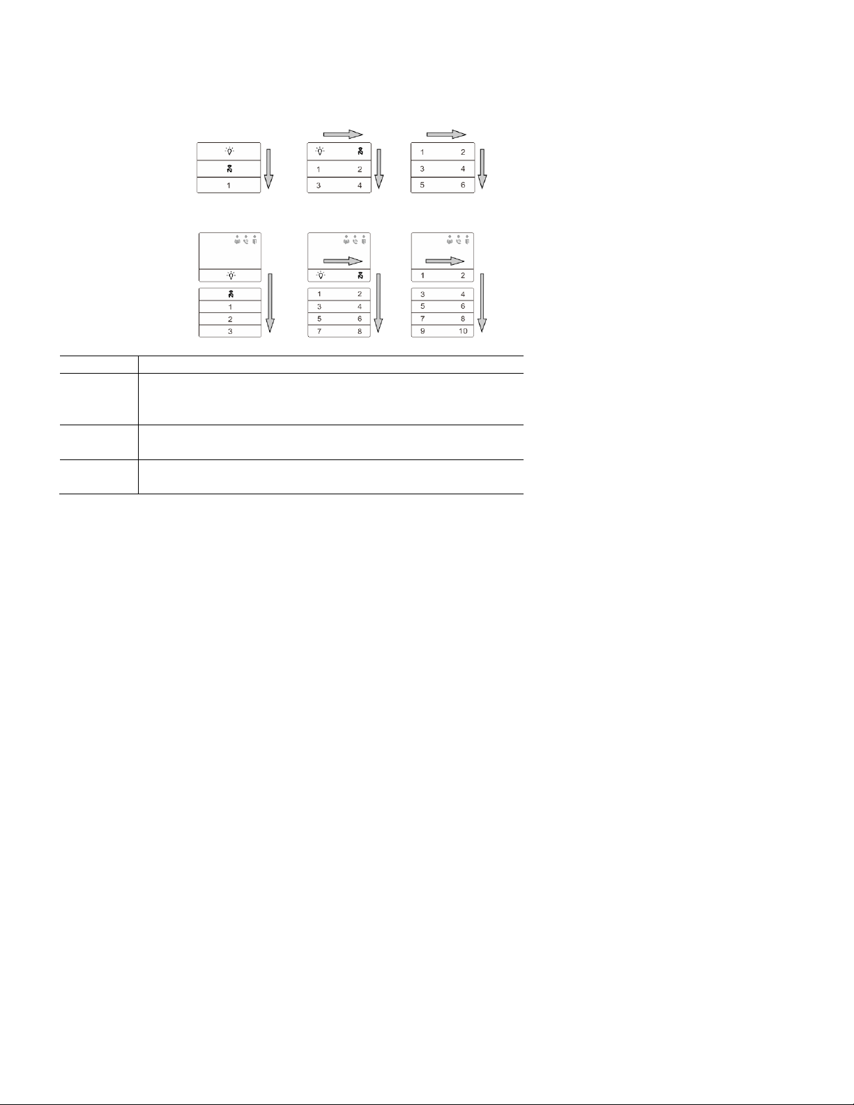
ABB Welcome
— 19 —
No.
Functions
1
Regardless of the structure of the pushbutton module, the button numbers
are listed from top to bottom and from left to right (in the double column
mode).
2
Lighting switch and call guard unit function is always assigned to the first
and second button.
3
User names can be printed by the using the labeling tool of the ABB
Welcome configuration software.
®
Page 20
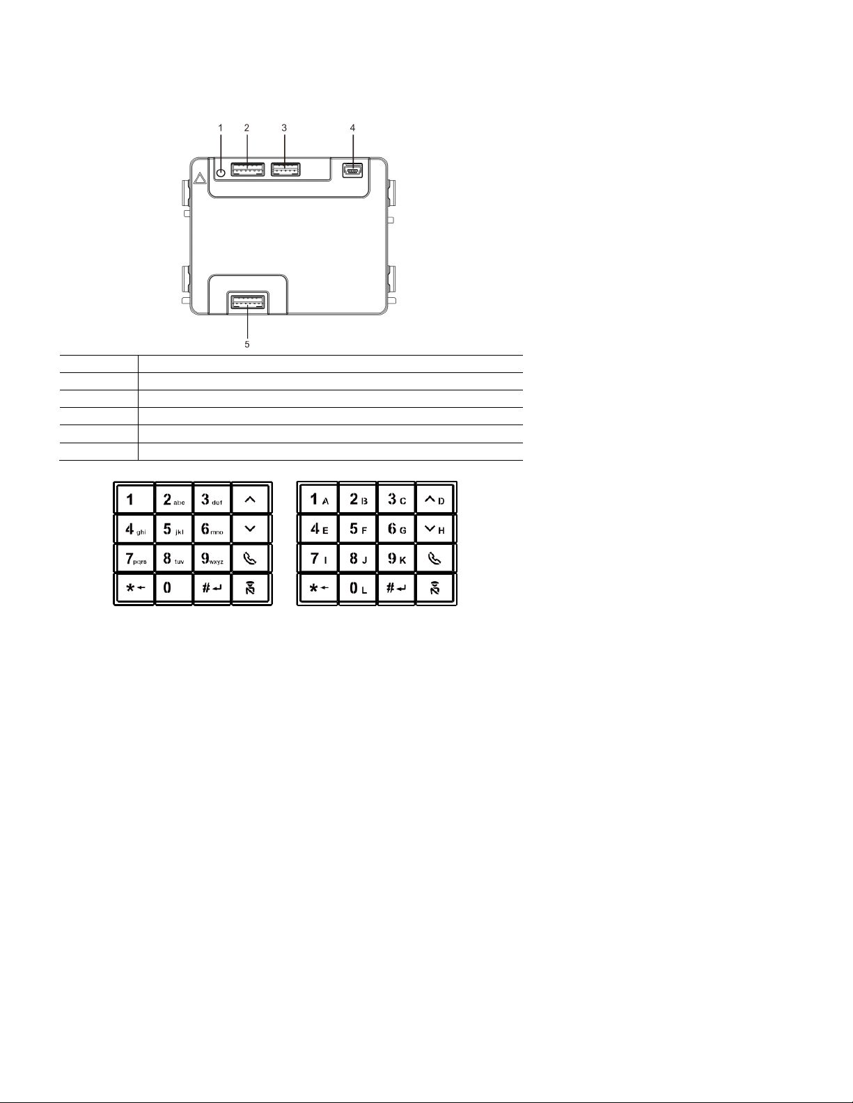
ABB Welcome
— 20 —
No.
Functions
1
Program button
2
Connector for previous module
3
Connector for device software update
4
USB connector for connection to a PC: Download/upload the configuration.
5
Connector for next module
®
4.5 Keypad module
Page 21
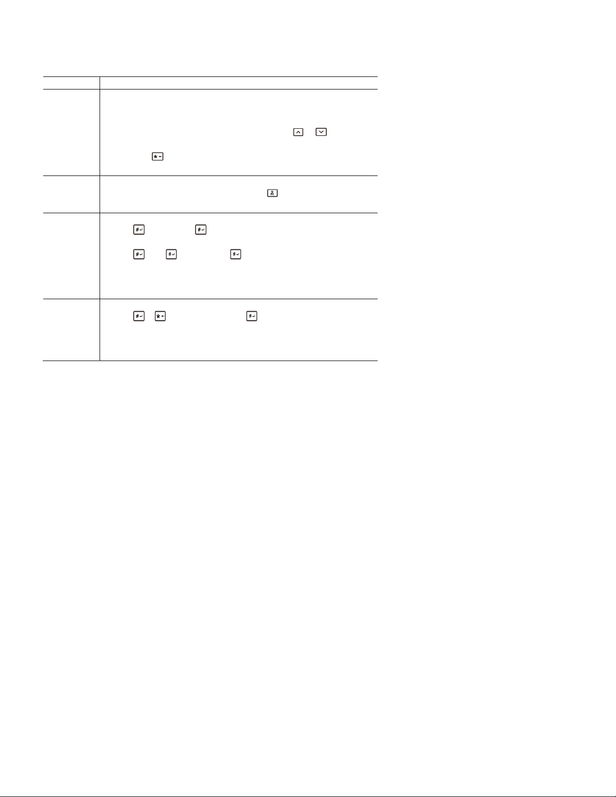
ABB Welcome
— 21 —
No.
Functions
1
Call resident
A visitor inputs an indoor station number (001) or apartment number (e.g. ,
0101, programmed in advance) to call a resident.
*Also, the visitor can select a resident name with the or buttons of
the accompanying display module to make a call.
Pressing the button will cancel the call.
*This function is only available in Fig. 1.
2
Calling the guard unit
A visitor can call a guard unit by pressing the button if the guard unit is
available in the system.
3
Unlocking by password
Press " + password+ “ to release the default lock to the audio
module.
Press " +2 + + password + " to release the 2nd lock connected
to the audio module.
The initial password is 123456. Residents can set their own customized
password with indoor stations.
4
System engineering configuration
Press " + + system password + " to enter the system
engineering configuration menu.
The initial system password is 345678, and it can be modified by the
administrator.
®
Page 22
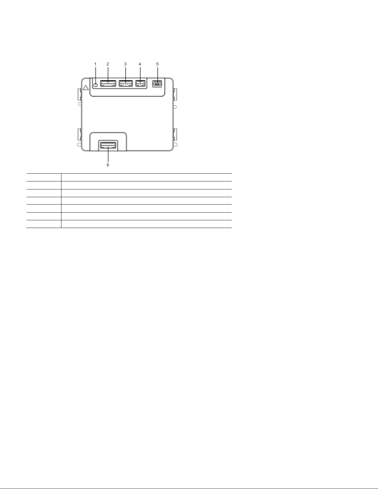
ABB Welcome
— 22 —
No.
Functions
1
Program button
2
Connector for previous module
3
Connector for device software update
4
Connector for Wiegand output
5
USB connector for connecting to a PC: Download/upload the configuration.
6
Connector for the next module
®
4.6 Display and card reader module
Page 23
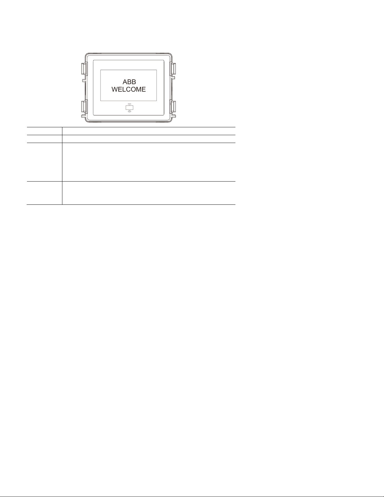
ABB Welcome
— 23 —
No.
Functions
1
LCD display
2
Support ID or IC card.
Swipe the registered card to release the door lock. The card can be
programmed through the module itself, or by using a PC to download the
program file. (M251021CR is accompanied by an ID card reader, while
the M251022CR is accompanied by an IC card reader.)
3
Support Wiegand output.
The default Wiegand format is 26 bits, but it can also be extended
to 34 bits.
®
*The display module must be connected after the audio module.
Page 24

ABB Welcome
— 24 —
Work
frequency
125 kHz
Standard
ISO18000-2
Support
card
EM4100, EM4205, EM4305, EM4450, TK4100, T5567
Output
format
Wiegand, 26- bit, 34-bit
Work
frequency
13.56 MHz
Standard
ISO 14443A
Support
card
Mifare® One S50/S70, etc.
Output
format
Wiegand, 26- bit, 34-bit
®
Technical specifications
M251021CR: Display module with ID card re ader
M251022CR: Display module with IC card re ader
Page 25

ABB Welcome
— 25 —
No.
Functions
1
Connector for previous module
2
Connector for next module
®
4.7 Nameplate module
Labeling of the nameplate module can be printed by using the labeling tool of the ABB Welcom e configuration software.
Page 26

ABB Welcome
— 26 —
No.
Functions
1
3->OFF, 4->OFF
2
Call apartment 01.
3
Call apartment 02.
4
Call apartment 03.
3 4 DIP
1
2
3
1
2 3 4
001
002
003
®
5 Operation
5.1 Pushbutton outdoor station
5.1.1 Addressing
1. Configure functions of the first and second pushbuttons
Page 27

ABB Welcome
— 27 —
No.
Functions
1
3->ON, 4->OFF
2
Switch on light. The light is connected with a switch actuator. The address
of the switch actuator must be the same as the address of this outdoor
station.
3
Call apartment 01.
4
Call apartment 02.
3
4
DIP
1
2
1
2 3 4
001
002
®
Page 28

ABB Welcome
— 28 —
No.
Functions
1
3->OFF, 4->ON
2
Call the guard unit. If there are multiple guard units in the same section, all
guard units will ring at the same time when a visitor presses the button “call
guard unit.”
3
Call apartment 01.
4
Call apartment 02.
No.
Functions
1
3->ON, 4->ON
2
Switch on lights.
3
Call guard unit.
4
Call apartment 01.
3 4 DIP 1 2
1
2 3 4
001
002
Guard unit
3
4
DIP
1
1
2 3 4
001
Guard unit
®
2. Configure pushbutton in single or double column modes
Page 29

ABB Welcome
— 29 —
No.
Functions
1
2->OFF
2
Call apartment 01.
3
Call apartment 02.
4
Call apartment 03.
5
Call apartment 04.
2
ON
1
2 3 5
1
2 3 4
4
001
002
003
004
®
Page 30

ABB Welcome
— 30 —
No.
Functions
1
2->ON
2
Call apartment 01.
3
Call apartment 02.
4
Call apartment 03.
5
Call apartment 04.
6
Call apartment 05.
7
Call apartment 06.
8
Call apartment 07.
9
Call apartment 08.
2
ON
1
3 5 9 7 2 4 8
6
2
4
6
8
1
3
5
7
001
001
002
003
004
005
006
007
008
®
Page 31

ABB Welcome
— 31 —
No.
Functions
1
2->ON, 3->ON, 4->ON
2
Switch on lights.
3
Call the guard unit.
4
Call apartment 01.
5
Call apartment 02.
6
Call apartment 03.
7
Call apartment 04.
8
Call apartment 05.
9
Call apartment 06.
3 4 DIP
1
2
ON
3
5 9 7 2 4 8 6
2
4
6 1 3
5
Guard unit
001
002
003
004
005
006
®
Page 32

ABB Welcome
— 32 —
1
2
3
4
2 4 6 8 3 5 7
Single column
Double column
1
1st button
®
5.1.2 Setting the language for voice messages (if the audio module has a speech synthesis function)
For the audio module with a speech synthesis function (M251024A-.), the local language can be set.
Set outdoor station address as “0” and hold the first button for 3 s econds to play the voice message.
Click on this button to select the language. After choosing the language, hold this button to save and exit the setting.
Page 33

ABB Welcome
— 33 —
Apartment 01 A
Apartment 02 B
Apartment 03 C
Apartment 04 A
Apartment 05 B
Apartment 06 C
Outdoor station
Left building
Apartment 01 A
Apartment 02 B
Apartment 03 C
Apartment 04 D
Apartment 05 E
Apartment 06 F
Outdoor station
Gate en trance
Outdoor station
Right building
®
Pushbutton outdoor station used as gate station
If pushbutton outdoor station is set as a gate station, a gateway must be used, and it must be configured in floor gateway mode.
For detailed information, please refer to the Gateway User Manual, floor gateway chapter.
Page 34

ABB Welcome
— 34 —
The display and card reader module c an be assem bled
with a pushbutton outdoor station. The user can swipe
cards to open the door. For this combination, a master
card is needed for an electrician to manage this outdoor
station.
Register a master card or deact ivate a master card. (We
recommend that this work be carried out by specialized
personnel.)
1. Disconnect the power supply.
2. Reconnect the power.
3. Within 30 seconds, hold the “program button” for 5
seconds to enter the "program master card"
interface within 30 seconds.
4. Any card swiped by the reader during this time will
be designated as the new master card. The prompt
“Register master card successfully” will appear on
the screen.
Please note that if you swipe this same card again,
the information will be deleted, and the prompt
“Delete master card successfully" will appear on the
screen.
Only one master card can be registered at a time.
®
5.2 Pushbutton outdoor station with display module
Enter system setting using master card:
1. Swipe the master card to enter the setting menu. Three LEDs will turn on.
2. Six options are available:
- Program card
- Language
- Wiegand output
- Choose door
- Date and time
- Back
There is a 5-s econd countdown for each option.
3. Swipe the master card again within 5 seconds to change to the next option.
Or, after 5 seconds has elapsed, the current option will be chosen.
4. After 30 seconds elapsed time, you will automatically be exited from t he setting m enu.
Page 35

ABB Welcome
— 35 —
Menu_________05
Program Card
Language
Wiegand Output ∨
Swipe the master
card
Menu_________05
Program Card ∧
Language
Wiegand Output ∨
Swipe the master card
within 5 seconds to move
to next option.
==>
Menu_________√
Program Card
Language
Wiegand Output ∨
After 5 seconds of elapsed
time, the curr ent option will
be chosen
==>
==>
Menu_________05
Program Card ∧
Language
Wiegand Output ∨
Swipe the master card
within 5 seconds to move
to next option
==>
==>
Proximity Card 05
Register Card
∧
Delete Card
Delete All ∨
Swipe the master card,
enter the setting
®
--- ∧
--- ∧
--------
---
Page 36

ABB Welcome
— 36 —
The keypad module can be assembled with a
pushbutton outdoor station, and users can enter the
password to open the door.
Users can enter the system settings menu by using the
following steps. (Press # to confirm and * to cancel. The
default system password is 345678.)
1. Set the device as an outdoor station or a gate
station.
Outdoor station:
#* system password # =>
1 # => 1 #
Gate Station:
#* system password # =>
1 # => 2 #
®
5.3 Pushbutton outdoor station with keypad module
2. Modify "system password"
#* system password # =>
2 # => Enter new password (6-8 characters) # => Enter the password again #
3. Modify "door open code"
#* system password # =>
3# => Enter new door open code (3-8 char acters) # => Enter the code again #
4. Set the voice message
If the audio module with the speech synthesis function (M251024A-.) is assembled, the local language can be set.
#* system password # =>
4# => Press or to choose the language => #
5. Enable or disable access control function
Enable access control function:
#* system password # =>
5# => 1 #
Disable access control function:
#* system password # => 5# => 2 #
Page 37

ABB Welcome
— 37 —
®
*Reset the system password of the keypad module:
It is possible to reset the system password to the factory setting if you have forgotten it.
The restoration of default factory settings does not delete the rest of the information programmed on the system, such as user names or
other settings.
1. Disconnect the power supply.
2. Reconnect the power.
3. Within 30 seconds hold the “program button” for 5 sec onds.
4. A beep tone will sound and the system password will be reset to the default (345678).
Page 38

ABB Welcome
— 38 —
Function
Command
LED
Create admin card
Swipe card 1x
Green
Enter settings
Swipe admi n card 1x
Orange
Function
Command
LED
Enroll user
Swipe admi n card 1x
Orange flash 1x
Swipe card (new u ser) 1x
Green
Delete user
Swipe admi n card 2x
Orange flash 2x
Swipe card (user x) 1x
Green
Enroll new admin
Swipe admi n card 3x
Orange flash 3x
Swipe card (new admin) 1x
Green
Delete admin
Swipe admi n card 4x
Orange flash 4x
Swipe card (admin x) 1x
Green
Delete all users
Swipe admi n card 5x
Orange flash quickly
Swipe admi n card 1x
Green
Function
Command
LED
Exit settings
Swipe admi n card 1x or no cards
swiped within 15 seconds
——
Function
Command
LED
Open a door
Swipe the enrolled keycard or mobile
phone with “Door Open” App installed.
Green
®
5.4 Round pushbutton outdoor station with IC or NFC
Enroll the cards
For the round pushbutton module with NFC or IC card reader, cards can be enrolled or deleted. A maximum of 500 cards can be supported.
Programming
The system will designa te th e firs t card swiped wi thin 60 seconds after
powering up the s ystem as the admin card.
After entering settings, the following functionalities can be implemented:
During setting, please swipe the same admin card.
Open a door
Page 39

ABB Welcome
— 39 —
Function
Command
LED
Reset to factory
default
Disconnect the power supply.
Reconnect the power supply.
Within 60 seconds, long-press the
“program” button for 5 seconds.
Finish re set.
——
White
Red, green,
orange cycl e
——
Work frequency
13.56 MHz
Standard
ISO 1444 3A
Support card
MIFARE One S50/S70, etc.
Output format
Wiegand, 24-bit, 34-bi t
Supported NFC devices
Most NFC mobile. (Not all; testing is needed before using this function.)
®
Reset to factory default
Technical s pecifications for round pushbutton module with IC orNFC:
Page 40

ABB Welcome
— 40 —
26-bit, green LED flash *1
34-bit, green LED flash *2
Switch on validation, green LED flash*1
Switch off validation, green LED flash*2
®
Set the Wiegand format
1. Swipe admin car d to enter system setting. (Orange LED is on. )
2. Short press first button to change the Wiegand format to 26-bit or 34-bit. (Default is 26-bit.)
The different format is indicated by the LED and sound feedback.
Switch off validation
In some case, users only register cards as a third party and not on the outdoor station. When users swipe these cards at the outdoor station, the
door will open, but an unnecessary warning indication will be displayed on dis play module. To eliminate this unnecessary warning, validation needs
to be switched off so it will not appear on the display module.
1. Swipe admin card to enter system setting. (Orange LED is on.)
2. Long press first button for 3 seconds to switch validation on/off. (Default validation is “on.”)
The on or off status is indicated by the LED and sound feedback.
Page 41

ABB Welcome
— 41 —
®
Use app to open door
The round push button module with NFC can be used for opening doors. Programming is performed directly on the module or via a web brows er
(requires IP Gateway 83342-500). Additional devices are not required for commissioning.
Access the Google Play store (https://play.google.com/store/apps/details?id=com.abb.all egro3_nfcdooropener&hl=en)
1. Download and install the ABB Door Opener App from Google Play Store.
2. Turn on the NFC function of your device.
3. Enter the setting mode of your round pushbutton module.
4. Start the app on your device.
5. Set up your device as a user.
6. Configure your personal settings.
Page 42

ABB Welcome
— 42 —
1. Physical address
The physical address is the internal code that the
outdoor station will send through the bus connection to
indoor stations or other devices in the system. For each
apartment, the physical address means the address of
an indoor station that is installed in the apartment. For
each building, the physical address means the address
of a gateway that is installed for each building. It is also
called the building number.
In standby mode, a visitor can press the physical
address corresponding to the residence (from 001 to
250).
For a complex building, a visitor needs to press the
building number (01- 60) plus the physical address (001
- 250), or make a call in the gate station.
Enter Physical
Add.:
®
5.5 Keypad outdoor station
5.5.1 Call a resident (three types)
01 001
2. Logical address
The logical address is a code that a visitor can press to make a call. The code must be assigned first and then associated with the physical
address.
Apartment numbers, which are easy for users to remember, are typically set as the logical addresses, but other special codes can also be
used.
Set the logical address by following these steps:
Assign the logical address:
#* system password # => system setting =>
Contact => Add => Logic Add.
Page 43

ABB Welcome
— 43 —
Physical Add.:
Logical Add.:
Call Mode_______
Physical Add. ∧
Logical Add.--------
==
>
No. of digit:
Physical Add.:
User Name:
®
001
0101
Turn on the “Logical address” call mode
#* system password # => system setting =>
Configurations => Call Mode
-4-
∨
3. Resident name
(Note: This function is only available for the outdoor station with keypad module (M251021K-.)
In standby mode, press the or the button to display resident names. Use the and buttons to search for the desired residential
station and press the to make a call.
A visitor can also enter the resident name using the keypad to make a call.
Resident names must be assigned first and then associated with the physical addr ess.
#* system password # => system setting
=> Contact => Add => User Names
(1-8 Digits)
01001
Federico
Page 44

ABB Welcome
— 44 —
30 s
“*“ to Cancel
==
>
120 s
“*“ to Cancel
Accept the call
30 s
“*“ to Cancel
==
>
120 s
“*“ to Cancel
Playing the message...
==
>
001 s
“*“ to Cancel
After a beep tone, visitor
can record a message
®
5.5.2 Call the guard unit
Press the button to make a call to a guard unit.
Guard Unit
Guard Unit
5.5.3 If an indoor station is in “leave home mode”
If an indoor station has been set in “leave home mode,” a visitor can record a message for the resident after entering the
following interface.
Andy
Andy
Recording...
Page 45

ABB Welcome
— 45 —
Guard unit accepts
the call
Guard unit transfers the
call to an indoor station
30 s
“*“ to Cancel
==
>
120 s
“*“ to Cancel
Call from an outdoor
station to an indoor
station
==
>
120 s
“*“ to Cancel
==
>
®
5.5.4 If a guard unit is in "intercept mode"
If a guard unit I set in “intercept mode,” a call from an outdoor station to an indoor station will be intercepted by the guard
unit. Once the caller’s identity has been confirmed, the guard unit can forward the call to the indoor station.
Guard Unit
Andy
Guard Unit
Page 46

ABB Welcome
— 46 —
Menu__________
Configurations
Access Control
Contact
Device Type_____
Outdoor St.
∧
Gate Station
Device Type_____
Outdoor St.
Gate Station
Call mode_______
Physical Add.
Logic Add.:
®
5.5.5 System settings
In settings, press “#” to confirm and “*” to cancel. The default system password is 345678.
1. Enter the system settings menu
#* system password #
-- ∧
∨
2. Configurations
(1) Set the device as an outdoor station or a gate station.
Outdoor station:
#* system password # =>
Configurations # => Device Type # => Outdoor St. # (Default)
● --
∨
Gate station:
#* system password # =>
Configurations # => Device Type # => Gate station #
(2) Set the call mode: Make a call by a physical address or a logical code.
Set the call mode by Physical Address:
#* system password # =>
Configurations # => Call mode # => Physical Address #
∧
●-
∨
●
Page 47

ABB Welcome
— 47 —
Call Mode_______
Physical Add.
Logical Add.:
New Password:
==
>
Re-enter:
==
>
Reset System
Code?
“#” to Confirm
“*” to Cancel
==
>
®
Set the call mode by a Logical Code (1-8 digits).
#* system password # =>
Configurations # => Call mode # => Logical Code #
∧
●-
∨
(3) System password setting
Modify the system password
#* system password # =>
Configurations # => System code # => Modify #
******
Reset the system password
#* system password # =>
Configurations # => System code # => Reset #
******
Done!
Done!
Page 48

ABB Welcome
— 48 —
Door Open Code__
Disable
Modify
Reset
==
>
New Password:
==
>
Re-enter:
==
>
Reset Door Open
Code?
“#“ to Confirm
“*“ to Cancel
==
>
®
3. Access control
(1) Door open code
The password can be set using 3 -8 digits. The default door open password is "123456” and it can be changed at an outdoor station.
Users can set their own passwords at the indoor stations. A total of 6,000 passwords can be stored.
Set the door open password ON/OFF (default: 123456)
#* system password # =>
Access Control # => Door open code # => Enable/disable #
-- ∧
∨
Modify the door open password
#* system password # =>
Access control # => Door open code # => Modify #
******
Reset the door open password
#* system password # =>
Access control # => Door open code # => Reset #
Done!
******
Done!
Done!
Page 49

ABB Welcome
— 49 —
Enter Card No.:
0123456
Or
Swipe the Card
==
>
Enter Card No.:
0123456
Or
Swipe the Card
Enter Card No.:
0123456
Or
Swipe the Card
==
>
Enter Card No.:
0123456
Or
Swipe the Card
Delete All
Cards?
“#” to Confirm
“*” to Cancel
==
>
Physical Add.:
001
User Name:
Alexander.G
®
(2) Proximity card (3,000 cards can be registered for outdoor station.)
Register cards:
#* system password # =>
Access control # => Proximity card # => Register card #
Done!
Delete cards:
#* system password # =>
Access control # => Proximity card # => Delete card #
Done!
4. Contact (3, 000 names using a combination of 24 alphanumeric characters)
Delete all cards
#* system password # =>
Contact # => Proximity card # => Delete All #
Done!
(1) Add
Add the contact by user names
#* system password # =>
Contact # => Add # => User Names #
Resident names must be associated with a physical address.
Page 50

ABB Welcome
— 50 —
Physical Add.:
001
Logical Add.:
0101
Alexander.G
Bodin.K
Christian.G
Enter Logical
Add.:
0101
Alexander.G
Bodin.K
Christian.G
®
Add the contact by logical address
#* system password # =>
Contact # => Add # => Logic add. #
Logical address must be associated with a physical address.
(2) Modify
Modify contact by user names
#* system password # =>
Contact # => Modify # => User Names #
-- ∧
∨
Modify the resident names with the corresponding physical address.
Modify contact by logical address
#* system password # =>
Contact # => Modify # => Logic add. #
Modify the logical address and its corresponding physical address using the alphanumeric keypad.
(3) Delete
Delete the contact by user name
#* system password # =>
Contact # => Delete # => User Names #
-- ∧
∨
Page 51

ABB Welcome
— 51 —
Enter Logical
Add.:
0101
Delete All Names?
“#” to Confirm
“*” to Cancel
==
>
®
Delete the contact by logical address
#* system password # =>
Contact # => Delete # => Logic add. #
(4) Clear all
#* system password # =>
Contact # => Clear all #
Done!
Clear all lists, including resident names and logical addr ess entries, from this menu.
Page 52

ABB Welcome
— 52 —
“#” to Confirm
==
>
Second-Lock Open
Time (1-10
seconds):
“#” to Confirm
==
>
Voice Message___
On
Off
==
>
This function is
not Available.
®
5. System setting
(1) Date and time
#* system password # =>
Settings # => Date & time # => Enter time and date => #
2016-01-01
07:00
Done!
(2) Door open time for second lock
#* system password # =>
Settings # => Door Open Time # => Time 1-10s (default: 3s) => #
Done!
3s
(3) Setting the voice message on or off
If you are using the audio module with speech synthesis function (M251024A-.), the speech synthesis function can be enabled or
disabled. The logical language can also be chosen.
#* system password # =>
Settings # => Voice message #
● -- ∧
Done!
∨
If your audio module does not have a speech synthesis function, this will be
indicated when you enter the menu.
Page 53

ABB Welcome
— 53 —
Language_______
English
Français
Italiano
New Message:
ABB Welcome!
“#” to Confirm
“*” to Cancel
==
>
Wiegand Output__
26-bit !
34-bit !
Choose Door____
First-Lock
∧
Second-Lock
®
(4) Select language
#* system password # =>
Settings # => Language #
● -- ∧
∨
(5) Welcome Message
#* system password # =>
Settings # => Welcome Msg. #
Done!
A total of 64 characters can be entered.
(6) Setting the Wiegand output digits
#* system password # =>
Settings # => Wiegand Output #
● -- ∧
∨
(7) Set the related door lock when swiping the card
#* system password # =>
Settings # =>Choose Door #
●
∨
Choose the lock to be released when the registered card is swiped:
Page 54

ABB Welcome
— 54 —
Reset to Factory
Default?
“#” to Confirm
“*” to Cancel
==
>
Audio module: ∧
V1.07_131106
Card reader:
V0.10_131107 ∨
(8) Reset
#* system password # =>
Settings # => Reset # => #
®
Done!
Reset all settings to factory settings, but other information, e.g., user names, logical addresses and card information, will not be reset.
(9) Information
#* system password # =>
Settings # => Information #
View the software information of each module of the outdoor station.
Page 55

ABB Welcome
— 55 —
®
*Reset the system password for the keypad module:
It is possible to reset the system password to factory settings if you have forgotten it.
The restoration of default factory settings does not delete the other information programmed on the system, such as user names or other
settings.
1. Disconnect the power supply.
2. Reconnect the power.
3. Within 30 seconds, hold the “program button” for 5 s econds.
4. A beep tone will sound, and the system password will be reset to the default (345678).
Page 56

ABB Welcome
— 56 —
In standby mode, a visitor can enter the physical
address corresponding to the residence to call
directly, from 001 to 250.
For a complex building, the visitor needs to press the
building number (01-60) plus physical address (001-
250) to make a call fr om a gate station.
®
5.6 Keypad outdoor station without display (camera + audio + keypad)
5.6.1 Calling a resident by inputting physical address
5.6.2 Call guard unit
Press the button to make a call to a guard unit.
5.6.3 System settings
Users can enter the system settings by following these steps. (In settings, press “#” to confirm, press “*” to cancel. The default system
password is 345678.)
1. Set the device as an outdoor station or a gate station.
Outdoor station:
#* system password # =>
1 # => 1 #
Gate station:
#* system password # =>
1 # => 2 #
2. Modify the "system password"
#* system password # =>
2 # => Enter new password (6-8 digits) # => Enter the password again #
3. Modify the "door open code"
#* system password # =>
3# => Enter new door open code (3-8 digits) # => Enter the code again #
4. Setting the voice message
If you are using the audio module with speech synthesis function (M251024A-.),
the local language can be set.
#* system password # =>
4# => Press or to choose the language => #
5. Enable or disable the access control function
Enable access control function:
#* system password # =>
5# => 1 #
Disable access control function:
#* system password # =>
5# => 2 #
Page 57

ABB Welcome
— 57 —
®
*Reset the system password for the keypad module:
It is possible to reset the system password to the factory setting if you have forgotten it.
The restoration of default factory settings does not delete the other information programmed on the system, such as user names or other
settings.
1. Disconnect the power supply.
2. Reconnect the power.
3. Within 30 seconds, hold the “program button” for 5 seconds.
4. A beep tone will sound, and the system password will be reset to the default (345678).
Page 58

ABB Welcome
— 58 —
®
6 Advanced configuration
Connect to a PC to configure the keypad or display.
Page 59

ABB Welcome
— 59 —
Designation
Value
Operating temperature
-40 °F to +158 °F
Protection (cover frame
assembled)
IP 54
Power supply, door opener
(Lock-GND)
18V, 4 A impulsive, 250 mA holding
Floating output, door opener
(COM-NC-NO)
30 V AC/DC 1A
Single-wire clamps
2 x 22 AWG - 2 x 18 AWG
Fine-wire clamps
2 x 22 AWG - 2 x 18 AWG
Bus voltage
20 V - 30 V
®
7 Technical data
Page 60

ABB Welcome
— 60 —
Warning
Electric voltage!
Direct or indirect contact with live components can cause dangerous
currents to flow through the body, which may result in electric shock,
burns or even death.
- Always disconnect the main power supply prior to installation
and/or disassembly.
- Work on the 110 V - 240 V supply system must be performed only
by qualified personnel.
Warning
Electric voltage!
Install the device only if you have the necessary qualifications.
- Incorrect installation endangers your life and that of the user
of the electrical system.
- Incorrect installation can cause serious damage to property,
e.g., fire.
The minimum necessary expert knowledge and requirements for the
installation are as follows:
- Apply the "five safety rules" (DIN VDE 0105, EN 50110):
1. Disconnect from power source
2. Secure against being re-connected
3. Ensure that there is no voltage
4. Connect to the earth
5. Cover or barricade adjacent live parts
- Wear suitable personal protective clothing.
- Use only suitable tools and measuring devices.
- Check the type of supply network (TN system, IT system, TT
system) to secure the following power supply conditions (classic
connection to ground, protective grounding, necessary additional
measures, etc.).
®
8 Mounting and installation
8.1 Requirements for the electrician
Page 61

ABB Welcome
— 61 —
The following installation situations must be avoided:
- Direct light
- Direct sunlight
- Extremely bright picture background
- Highly reflective walls on the opposite side of the door station
- Lamps or direct light sources
8.2 General installation instructions
- Terminate all branches of the wiring system via a connected bus device (e.g., indoor station, outdoor station, system device).
- Do not install the system controller directly next to the bell transformer or other power supplies (to avoid interference).
- Do not install the wires of the system bus together with 100 V - 240 V wires.
- Do not use common cables for the connecting wires of the door openers and wires of the system bus.
- Avoid bridges between different cable types.
- Use only two wires for the system bus in a four-core or multi-core cable.
- When looping, never install the inc oming and outgoing bus inside the same cable.
- Never install the internal and external bus inside the same cable.
®
Page 62

ABB Welcome
— 62 —
Wear gloves to protect your
hands from possible laceration.
Audio module
Camera module
Nameplate module
Pushbutton module
Keypad module
Display and card reader
module
8.3 Mounting
®
Dimension
Page 63

ABB Welcome
— 63 —
Cover frame
Flush-mounted
®
Page 64

ABB Welcome
— 64 —
No.
Functions
1
Cover frame
2
Modules
3
Flush-mounted box
4
Rain hood
Rain hood
1
3
2
4
®
Components of the outdoor station
Page 65

ABB Welcome
— 65 —
®
Mount each module in the cover frame
1. Insert each module into the cover frame from behind until it click s into place. All m odules can be ins erted, e.g., the camera module,
audio module, pushbutton module, keypad module, dis play and card reader module, nameplate module.
2. Pay special attention to the top-to-bottom orientation of each module.
Module wiring
1. Use cables to connect the modules together one by one.
2. Ensure that the audio module is connected next to the camera module.
Page 66

ABB Welcome
— 66 —
®
The distance zones for the installation of the outdoor station
When selecting the installation site, ensure that the minimum distance to the right side is adhered to for removal of the end strip.
Page 67

ABB Welcome
— 67 —
Wires
®
1. Prepare the installation box.
2. Strip the wires.
– The insulated section of the cable end must not be longer than .039".
Assemble the frame into the flush-mounted box
1. Hang the device in the installation box.
2. Fasten the safety loop.
3. Connect the wires into the enclosed clamp, and plug the clamp onto the contact pins. Fold the device and shut it until it audibly snaps
in.
4. Screw on the front of the device.
Page 68

ABB Welcome
— 68 —
®
Four types of installation
Option 1: Flush mounted with only flush-mounted box
Option 2: Flush mounted with a rain hood
Option 3: Surface mounted with a rain hood
Page 69

ABB Welcome
— 69 —
®
Option 4: Cavity wall installation
Page 70

ABB Welcome
— 70 —
®
Dismounting the outdoor station
1. Use the enclosed mounting tool to remove the end strip.
2. Remove the screw that is used to affix the cover frame.
3. Push up and pull out the outdoor station on the bottom of the cover frame.
Dismounting the modules
1. Dismount the module from one side of the frame.
2. Remove the modules.
Page 71

ABB Welcome
— 71 —
®
Replacing the nameplates
1. Remove the pushbutton cover and write the user names on the labels.
2. Use a labeling sheet with appropriate software to correctly format and print
the labels.
Page 72

ABB Welcome
— 72 —
®
Adjusting the angle of the camera
Fig. 1 Adjust the angle of the camera
1. Unscrew the camera.
2. Adjust the angle of the camera in four directions (up, down, right and left).
3. Screw on the camera.
Page 73

ABB Welcome
— 73 —
®
Extending the outdoor station
1. Make a hole for the cable.
2. Use the joining fixtures to assemble the flush-mounted boxes horizontally.
3. Run the connection wires between the boxes.
*The extension is useful for multi-outdoor station connections .
Page 74

—
ABB Inc.
Electrification Products
860 Ridge Lake Blvd.
Memphis, TN 38120
www.abb.com/door-entry-system-us
abbwelcomeinfo@us.abb.com
Customer Service: 800-816 -7809
7:00 a.m. - 5:30 p.m., CST, Monday-Friday
elec_custserv@tnb.com
Technical Support: 888-385-1221, Option 1
7:00 a.m. - 5:00 p.m., CST, Monday-Friday
lvps.support@us.abb.com
—
We reserve the right to make technical
changes or modify the contents of this
document without prior notice. With regard
to purchase orders and/or contracts, the
agreed particulars shall prevail. ABB Inc.
does not accept any responsibility whatsoever for potential errors or possible lack
of information in this document.
We reserve all rights in this document and in
the subject matter and illustrations contained
therein. Any reproduction, disclosure to third
parties or utilization of its contents - in whole
or in parts - is forbidden without prior written
consent of ABB Inc.
© Copyright 2018 ABB. All rights reserved.
1SXU4600 68M0201, June 2018
 Loading...