

Page 1

piccolo® xpress™ Chemistry Analyzer
Abaxis, Inc.
3240 Whipple Road
Union City, CA, USA
94587
Abaxis Europe
Heidelberger Landstrasse 230
D-64297 Darmstadt
Operator’s Manual
For In-Vitro Diagnostic Use Only
Customer and Technical Support: 1-800-822-2947
PN: 1100-7008 Manual Text, Rev. B
PN: 1100-7009 Manual Assembly, Rev. A
© 2006, Abaxis, Inc.
Page 2

Page 3

Table of Contents
Section 1: General Information. . . . . . . . . . . . . . . . . . . . . . . . . . . . . . . . . . . . . . . . . . . . . . . . . 1-1
1.1 Intended Use . . . . . . . . . . . . . . . . . . . . . . . . . . . . . . . . . . . . . . . . . . . . . . . . . . . . 1-1
1.2 Universal Precautions . . . . . . . . . . . . . . . . . . . . . . . . . . . . . . . . . . . . . . . . . . . . . 1-1
1.3 Introduction . . . . . . . . . . . . . . . . . . . . . . . . . . . . . . . . . . . . . . . . . . . . . . . . . . . . . 1-2
1.4 Technical Support . . . . . . . . . . . . . . . . . . . . . . . . . . . . . . . . . . . . . . . . . . . . . . . . 1-3
1.5 Symbols Used in Labeling . . . . . . . . . . . . . . . . . . . . . . . . . . . . . . . . . . . . . . . . . 1-3
Section 2: Setup and Description . . . . . . . . . . . . . . . . . . . . . . . . . . . . . . . . . . . . . . . . . . . . . . . 2-1
2.1 Unpacking . . . . . . . . . . . . . . . . . . . . . . . . . . . . . . . . . . . . . . . . . . . . . . . . . . . . . . 2-1
2.2 Physical & Environmental Specifications. . . . . . . . . . . . . . . . . . . . . . . . . . . . . . 2-2
2.3 Setup . . . . . . . . . . . . . . . . . . . . . . . . . . . . . . . . . . . . . . . . . . . . . . . . . . . . . . . . . . 2-2
2.4 piccolo xpress™ System Description . . . . . . . . . . . . . . . . . . . . . . . . . . . . . . . . . 2-4
2.5 Touchscreen and Front Panel . . . . . . . . . . . . . . . . . . . . . . . . . . . . . . . . . . . . . . . 2-5
2.6 Reagent Discs . . . . . . . . . . . . . . . . . . . . . . . . . . . . . . . . . . . . . . . . . . . . . . . . . . . 2-7
2.7 Ancillary Products. . . . . . . . . . . . . . . . . . . . . . . . . . . . . . . . . . . . . . . . . . . . . . . . 2-9
Section 3: Testing and Results . . . . . . . . . . . . . . . . . . . . . . . . . . . . . . . . . . . . . . . . . . . . . . . . . 3-1
3.1 Sample Requirements . . . . . . . . . . . . . . . . . . . . . . . . . . . . . . . . . . . . . . . . . . . . . 3-1
3.2 Preparing the Reagent Disc . . . . . . . . . . . . . . . . . . . . . . . . . . . . . . . . . . . . . . . . . 3-2
3.3 Running a Patient Sample . . . . . . . . . . . . . . . . . . . . . . . . . . . . . . . . . . . . . . . . . . 3-4
3.4 Canceling Analysis . . . . . . . . . . . . . . . . . . . . . . . . . . . . . . . . . . . . . . . . . . . . . . . 3-10
3.5 Results . . . . . . . . . . . . . . . . . . . . . . . . . . . . . . . . . . . . . . . . . . . . . . . . . . . . . . . . . 3-11
3.6 Testing Procedure Summary . . . . . . . . . . . . . . . . . . . . . . . . . . . . . . . . . . . . . . . . 3-13
Section 4: Configuring the Analyzer . . . . . . . . . . . . . . . . . . . . . . . . . . . . . . . . . . . . . . . . . . . . 4-1
4.1 Using the Settings Screens . . . . . . . . . . . . . . . . . . . . . . . . . . . . . . . . . . . . . . . . . 4-2
4.2 Customizing Reference Ranges. . . . . . . . . . . . . . . . . . . . . . . . . . . . . . . . . . . . . . 4-2
4.3 Printing and Archiving Reference Ranges . . . . . . . . . . . . . . . . . . . . . . . . . . . . . 4-12
4.4 Retrieving Reference Ranges . . . . . . . . . . . . . . . . . . . . . . . . . . . . . . . . . . . . . . . 4-14
4.5 Transmitting Reference Ranges . . . . . . . . . . . . . . . . . . . . . . . . . . . . . . . . . . . . . 4-16
4.6 Viewing Analyzer Identification . . . . . . . . . . . . . . . . . . . . . . . . . . . . . . . . . . . . . 4-17
4.7 Changing Date and Time. . . . . . . . . . . . . . . . . . . . . . . . . . . . . . . . . . . . . . . . . . . 4-18
4.8 Selecting the Language . . . . . . . . . . . . . . . . . . . . . . . . . . . . . . . . . . . . . . . . . . . . 4-19
4.9 Selecting Units . . . . . . . . . . . . . . . . . . . . . . . . . . . . . . . . . . . . . . . . . . . . . . . . . . 4-20
4.10 Setting Sound Volumes. . . . . . . . . . . . . . . . . . . . . . . . . . . . . . . . . . . . . . . . . . . . 4-24
4.11 Adjusting the Display . . . . . . . . . . . . . . . . . . . . . . . . . . . . . . . . . . . . . . . . . . . . . 4-25
4.12 Printer Settings . . . . . . . . . . . . . . . . . . . . . . . . . . . . . . . . . . . . . . . . . . . . . . . . . . 4-28
4.13 Setting Communication Protocol . . . . . . . . . . . . . . . . . . . . . . . . . . . . . . . . . . . . 4-32
4.14 Using Optional Data Functions . . . . . . . . . . . . . . . . . . . . . . . . . . . . . . . . . . . . . . 4-33
4.15 Running Controls . . . . . . . . . . . . . . . . . . . . . . . . . . . . . . . . . . . . . . . . . . . . . . . . 4-34
Table of Contents TOC-1
Page 4

Section 5: Recalling Results . . . . . . . . . . . . . . . . . . . . . . . . . . . . . . . . . . . . . . . . . . . . . . . . . . . 5-1
5.1 Recalling the Results of the Last Disc Run. . . . . . . . . . . . . . . . . . . . . . . . . . . . . 5-2
5.2 Searching for Results. . . . . . . . . . . . . . . . . . . . . . . . . . . . . . . . . . . . . . . . . . . . . . 5-3
5.3 Browsing Results. . . . . . . . . . . . . . . . . . . . . . . . . . . . . . . . . . . . . . . . . . . . . . . . . 5-8
5.4 Transmitting All Results . . . . . . . . . . . . . . . . . . . . . . . . . . . . . . . . . . . . . . . . . . . 5-10
Section 6: Calibration & Q. C. . . . . . . . . . . . . . . . . . . . . . . . . . . . . . . . . . . . . . . . . . . . . . . . . . 6-1
6.1 Calibration . . . . . . . . . . . . . . . . . . . . . . . . . . . . . . . . . . . . . . . . . . . . . . . . . . . . . . 6-1
6.2 Quality Control Features . . . . . . . . . . . . . . . . . . . . . . . . . . . . . . . . . . . . . . . . . . . 6-1
6.3 Running External Controls . . . . . . . . . . . . . . . . . . . . . . . . . . . . . . . . . . . . . . . . . 6-3
Section 7: Troubleshooting. . . . . . . . . . . . . . . . . . . . . . . . . . . . . . . . . . . . . . . . . . . . . . . . . . . . 7-1
7.1 Error Messages . . . . . . . . . . . . . . . . . . . . . . . . . . . . . . . . . . . . . . . . . . . . . . . . . . 7-1
7.2 Electrostatic Discharge . . . . . . . . . . . . . . . . . . . . . . . . . . . . . . . . . . . . . . . . . . . . 7-1
7.3 Technical Support . . . . . . . . . . . . . . . . . . . . . . . . . . . . . . . . . . . . . . . . . . . . . . . . 7-1
7.4 Disc Cancellations. . . . . . . . . . . . . . . . . . . . . . . . . . . . . . . . . . . . . . . . . . . . . . . . 7-1
7.5 Instrument and Result Messages . . . . . . . . . . . . . . . . . . . . . . . . . . . . . . . . . . . . . 7-2
7.6 Reinitializing the Analyzer . . . . . . . . . . . . . . . . . . . . . . . . . . . . . . . . . . . . . . . . . 7-4
Section 8: Operating Principles . . . . . . . . . . . . . . . . . . . . . . . . . . . . . . . . . . . . . . . . . . . . . . . . 8-1
8.1 Principles of Procedure . . . . . . . . . . . . . . . . . . . . . . . . . . . . . . . . . . . . . . . . . . . . 8-1
8.2 Principles of Operation . . . . . . . . . . . . . . . . . . . . . . . . . . . . . . . . . . . . . . . . . . . . 8-2
Section 9: Maintenance & Service . . . . . . . . . . . . . . . . . . . . . . . . . . . . . . . . . . . . . . . . . . . . . . 9-1
9.1 Cleaning the Analyzer . . . . . . . . . . . . . . . . . . . . . . . . . . . . . . . . . . . . . . . . . . . . . 9-1
9.2 Cleaning Spills . . . . . . . . . . . . . . . . . . . . . . . . . . . . . . . . . . . . . . . . . . . . . . . . . . 9-2
9.3 Cleaning the Air Filter. . . . . . . . . . . . . . . . . . . . . . . . . . . . . . . . . . . . . . . . . . . . . 9-2
9.4 Updating the Analyzer Software . . . . . . . . . . . . . . . . . . . . . . . . . . . . . . . . . . . . . 9-3
9.5 Returning the Analyzer to the Manufacturer for Service . . . . . . . . . . . . . . . . . . 9-4
Section 10: Connecting a Computer/Printer . . . . . . . . . . . . . . . . . . . . . . . . . . . . . . . . . . . . . . . 10-1
10.1 Connecting an External Printer . . . . . . . . . . . . . . . . . . . . . . . . . . . . . . . . . . . . . . 10-1
10.2 Connecting a Computer. . . . . . . . . . . . . . . . . . . . . . . . . . . . . . . . . . . . . . . . . . . . 10-1
10.3 Transmission Specifications . . . . . . . . . . . . . . . . . . . . . . . . . . . . . . . . . . . . . . . . 10-2
10.4 Installing the Abaxis® Driver . . . . . . . . . . . . . . . . . . . . . . . . . . . . . . . . . . . . . . . 10-3
10.5 Setting Up HyperTerminal . . . . . . . . . . . . . . . . . . . . . . . . . . . . . . . . . . . . . . . . . 10-10
10.6 Capturing Results with HyperTerminal . . . . . . . . . . . . . . . . . . . . . . . . . . . . . . . 10-13
INDEX . . . . . . . . . . . . . . . . . . . . . . . . . . . . . . . . . . . . . . . . . . . . . . . . . . . . . . . . . . . . . . . . . . . I-1
TOC-2 Table of Contents
Page 5
Section 1
General Information
1.1 Intended Use
The piccolo xpress™ chemistry analyzer provides quantitative in-vitro
determinations of clinical chemistry analytes in lithium-heparinized
whole blood, heparinized plasma, or serum.
CAUTION: If the piccolo xpress™ chemistry analyzer is used
in any way other than described in this manual,
the analyzer may not operate as intended, may
produce inaccurate or no results, and may pose a
safety hazard.
®
Note: Use only piccolo
piccolo xpress™ chemistry analyzer.
reagent discs with the
1.2 Universal Precautions
Operator health and safety regulations require that Universal Precautions
be observed at all times while handling human blood samples or work-
ing with the piccolo xpress™ chemistry analyzer in any way. For details,
see OSHA 29 CFR Part 1910 (“Occupational Safety and Health Stan-
dards”), Standard Number 1910.1030 (“Toxic and Hazardous Sub-
stances: Bloodborne Pathogens”), which can be found on the Internet by
going to http://www.osha.gov and searching for “1910.1030”.
For further guidelines on handling and disposing of hazardous labora-
tory wastes, refer to “Clinical Laboratory Waste Management; Approved
Guideline—Second Edition” (GP5-A2), from the Clinical and Labora-
tory Standards Institute (formerly NCCLS). This can be found on the
Internet at http://www.clsi.org.
General Information 1-1
Page 6

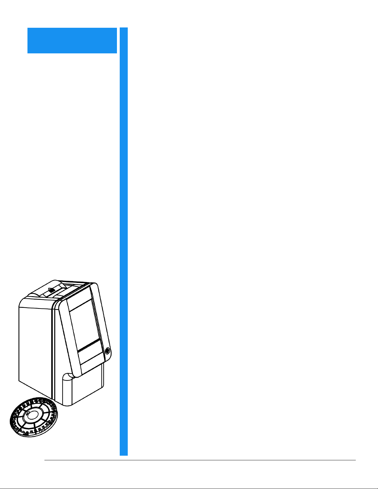
1.3 Introduction
The piccolo xpress™ chemistry system is compact and easy to transport. The system consists of a
portable analyzer and single-use disposable reagent discs. The analyzer contains the following
features and components:
■ a variable-speed motor to spin the disc
■ a photometer to measure analyte concentrations
■ two microprocessors to control testing and analytical functions
■ a thermal line printer to print out results
■ a VGA color touchscreen for communicating with the analyzer
■ optional data functions for more detailed analysis information
Each reagent disc is self-contained clear plastic, 8 cm in diameter and 2 cm thick, and containing
an aqueous diluent in its center and dry reagent beads in cuvettes around its edge. All blood sepa-
ration and sample diluent mixing is performed within the disc itself.
To perform an analysis, the operator needs only to collect a blood sample (lithium-heparinized
whole blood or plasma, serum), place the sample in the reagent disc, put the disc into the analyzer
drawer on the front of the analyzer, and input patient information. When analysis is finished, the
results print automatically.
Results are printed on thermal paper with adhesive backing for inclusion within the patient's med-
ical record. Five USB ports are provided so data can be sent to an external printer, computer,
memory stick, or laboratory information systems/electronic medical record systems (LIS/EMR).
The entire analysis requires ~100 μL of sample and is capable of providing results in about
12 minutes.
Note: This manual includes a number of analyzer screens and computer
screen captures. The analyzer screens are illustrations only, not exact
duplications. All screens represent typical use and installations, and
may differ in some minor details from the screens on your system.
1-2 General Information
Page 7
1.4 Technical Support
Abaxis Technical Support personnel are trained to answer questions regarding the operation of the
piccolo xpress™ chemistry analyzer. Call Abaxis Technical Support at 800-822-2947.
1.5 Symbols Used in Labeling
The following symbols are found on the back of the analyzer on the piccolo xpress™ label and
above the connectors.
Direct current.
!
Caution. Refer to any accompanying documents.
Biohazard. In accordance with good laboratory practice, consider all
material from human sources to be potentially infectious, and handle
them with the same precautions used with patient specimens (see
Section 1.2).
USB connection.
General Information 1-3
Page 8

1-4 General Information
Page 9
Section 2
Setup and Description
2.1 Unpacking
1. Remove the piccolo xpress™ chemistry analyzer from the ship-
ping carton. Place the analyzer on a level surface that is free of
hair, dust, and other contaminants. Do not place the analyzer
near a sunny window or any other heat source.
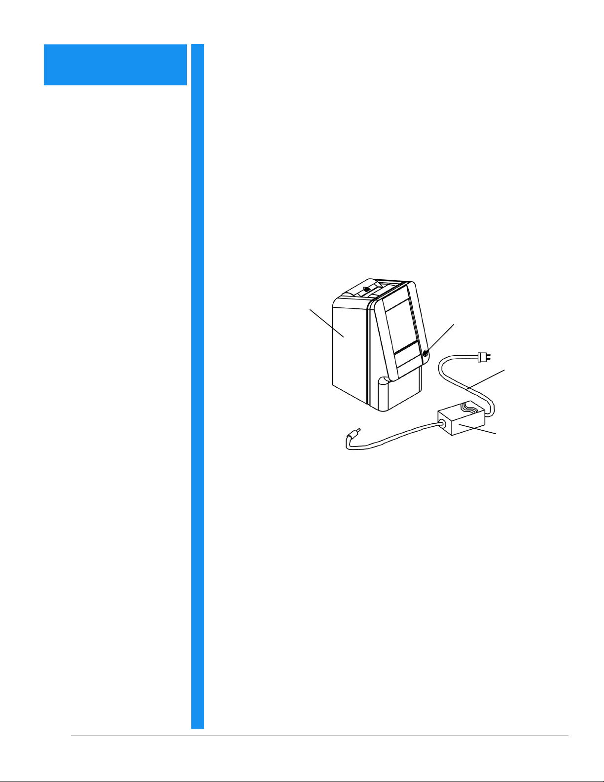
2. Check the components received with the piccolo xpress™
against the following figure to make sure everything required to
set up the analyzer is included.
piccolo xpress™
chemistry analyzer
Power button
Power cord
Power adapter
with cord
The shipping carton also includes a USB cable, Abaxis Driver
CD, piccolo xpress™ Operator's Manual (this manual), Warranty
card, and Start-up kit (not shown above).
3. After setup, complete the warranty card and mail it to Abaxis
within 10 days to start the warranty period. Customers are placed
on the customer mailing list to receive any information pertain-
ing to the piccolo xpress™ and ancillary products, such as soft-
ware upgrades.
®
Setup and Description 2-1
Page 10

2.2 Physical & Environmental Specifications
Analyzer dimensions: Height: 32.4 cm (12.75 inches)
Width: 15.2 cm (6 inches)
Depth: 20.3 cm (8 inches)
Weig ht: Analyzer: 5.1 kg (11.2 pounds)
Power adapter: 0.7 kg (1.6 pounds)
Protection against ingress of fluids:
Ambient operating temperature:
Thermal protection rating:
2.3 Setup
Mode of operation:
Altitude:
Humidity:
Reaction temperature:
Power requirements:
Main supply voltage:
Transient overvoltages:
Pollution:
Continuous
Ordinary equipment (IPXO)
2000 m (6562 ft)
0–40 ºC (32–104 ºF), indoor use
80% relative humidity for temperatures up to 31 ºC
(88 ºF), decreasing linearly to 50% relative humidity
at 40 ºC (104 ºF)
37 ºC (98.6 ºF)
70 ºC (158 ºF)
100–240 volts AC, 50–60 Hz or 15 Volts DC, 5.0A
Main unit: 1.1 to 0.45 amps, 15 volts DC, 5.0 A
Fluctuations not to exceed
voltage
Installation Category II in accordance with
UL 61010A-1 first edition Annex J
Degree 2 in accordance with IEC 664
± 10% of the nominal
1. Set up the piccolo xpress™ on a surface as follows:
■ Level.
■ Free of vibration and sudden jolts.
■ Free of hair, dust, and other contaminants.
■ Located in an ambient operating temperature of 15–32 ºC (59–90 ºF).
■ Away from sunny windows and all other potential heat sources.
■ At least six inches from any wall to provide adequate ventilation and access to the
power connection and USB ports.
2-2 Setup and Description
Page 11
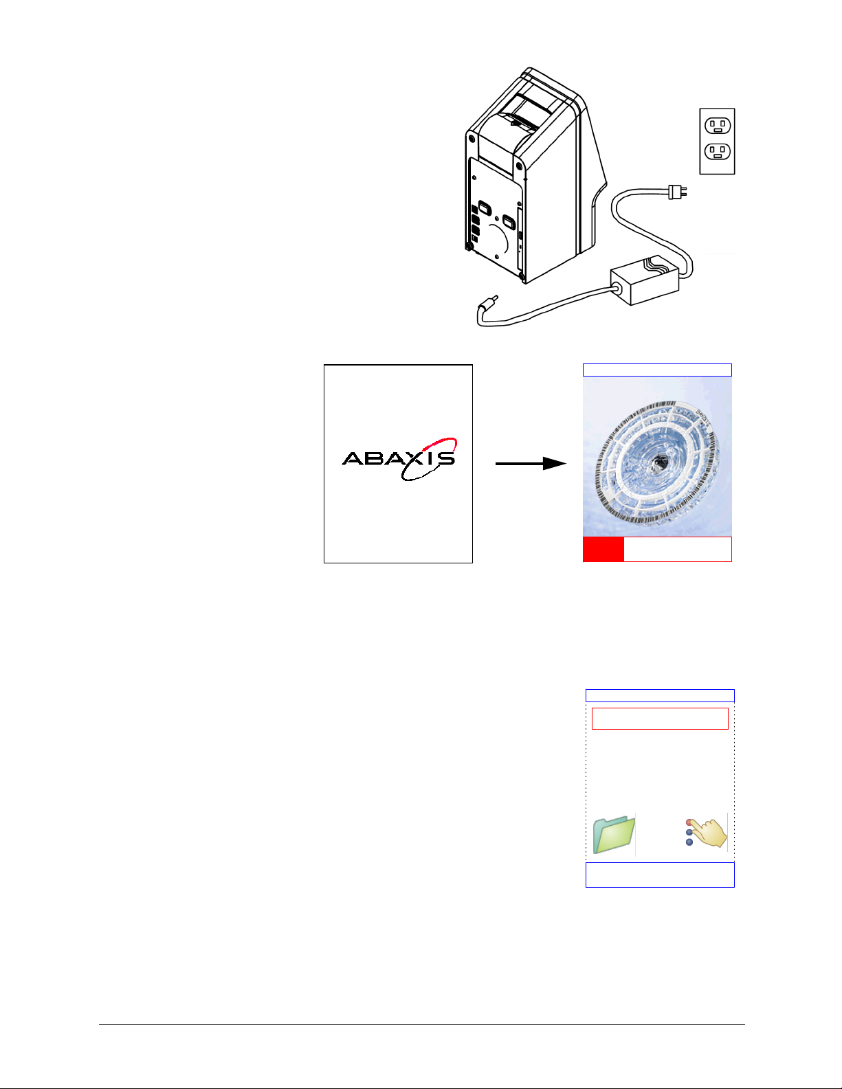
2. Plug the power jack into the analyzer, then
plug the detachable power supply cord into
the power adapter and into a grounded elec-
trical outlet.
CAUTION: To prevent power surges or drain,
DO NOT plug the analyzer into
the same circuit as a centrifuge or
any other high-current device.
Abaxis also recommends using a
surge protector of the same type
used for computers.
3. Press the Power button
to turn on the analyzer.
The display then shows
the following:
Note: If the display is blank (shows no message), remove the plug from the
power adapter, then re-insert the plug and press firmly to make sure it
seats correctly.
During the warming period, the display reads as shown:
piccolo xpress V1.2.3.4
Performing iQC...
Home
Warming Up
Monday 16 Aug 2006 10:30AM
Setup and Description 2-3
Page 12
4. After passing the self test and reaching operating temperature,
the analyzer is ready to run the first reagent disc, and displays
“Analyze”:
See Section 6.2, “Quality Control Features” for details about
the analyzer self test. The analyzer may require additional time
for the heaters to warm the analyzer to operating temperature.
5. Check the analyzer date and time to ensure they are correct.
Home
Analyze
Refer to Section 4.7, “Changing Date and Time” for directions.
Monday 16 Aug 2006 10:45AM
6. The analyzer can be connected to an external computer or
printer to transmit or print patient and control results. See Section 10, “Connecting a Com-
puter/Printer” for instructions.
7. Reference ranges are preset when the analyzer is shipped from the factory. The range val-
ues can be changed using the Customizing Reference Range feature described in
Section 4.2.
2.4 piccolo xpress™ System Description
The piccolo chemistry system consists of a portable analyzer and
disposable single-use reagent discs. Each reagent disc contains all
the reagents needed to perform a panel of tests on a single sample.
Be sure to become familiar with the system before running samples.
The piccolo xpress™ analyzer uses centrifugal and capillary forces to process heparinized whole
blood samples and distribute diluted plasma to the reaction chambers (cuvettes) in the reagent
disc. Serum and heparinized plasma samples are processed in a similar manner. The analyzer opti-
cally measures the chemical reactions and calculates analyte concentrations from these measure-
ments and from encoded calibration data contained on the bar code ring on the reagent disc.
Results are stored in memory, and can be printed using the built-in thermal printer or downloaded
to an external personal computer for data management.
2-4 Setup and Description
Page 13

The touchscreen display provides easy communication with the analyzer. The touchscreen shows
procedural instructions, indicates the status of the analyzer, and presents any error messages. For
details, see Section 2.5.
The reagent disc drawer slides out from the front of the analyzer, and transports the reagent disc
(see Section 2.6) into the analyzer and automatically positions it for analysis.
The analyzer prints results on adhesive-backed thermal paper tape, through its internal printer.
The external power adapter changes the electrical outlet voltage to DC voltage required by the
analyzer. Two power supply cords are provided: one cord is connected to the power adapter and
plugs into the back of the analyze, while the other connects the power adapter to a surge protector
designed for use with a computer.
The analyzer has several USB connectors. Use the top USB connector for connecting to an exter-
nal computer (see Section 10, “Connecting a Computer/Printer” for details).
The analyzer is easy to carry using the recessed handle incorporated into the top of the unit.
2.5 Touchscreen and Front Panel
You’ll use the analyzer’s touchscreen display to operate the analyzer.
■ Use the ten numbers on the touchscreen to input patient information.
■ The left and right arrow touchscreen keys move the display cursor forward or
backward to change a number on the display. The right arrow key ( ) functions
as a dash (–) when entering a patient identification number. The left arrow key
( ) functions as a backspace.
■ Use the up (S) and down (T) arrow keys to scroll through a displayed list of
items, or to increase or decrease a displayed value.
■ Operating functions are available through various icons on the touchscreen, as well
as specific keys that appear on the touchscreen according to the actions performed.
■ Press Back on the touchscreen to cancel a choice and return to the previous screen,
or to move backward through a series of screens.
Setup and Description 2-5
Page 14
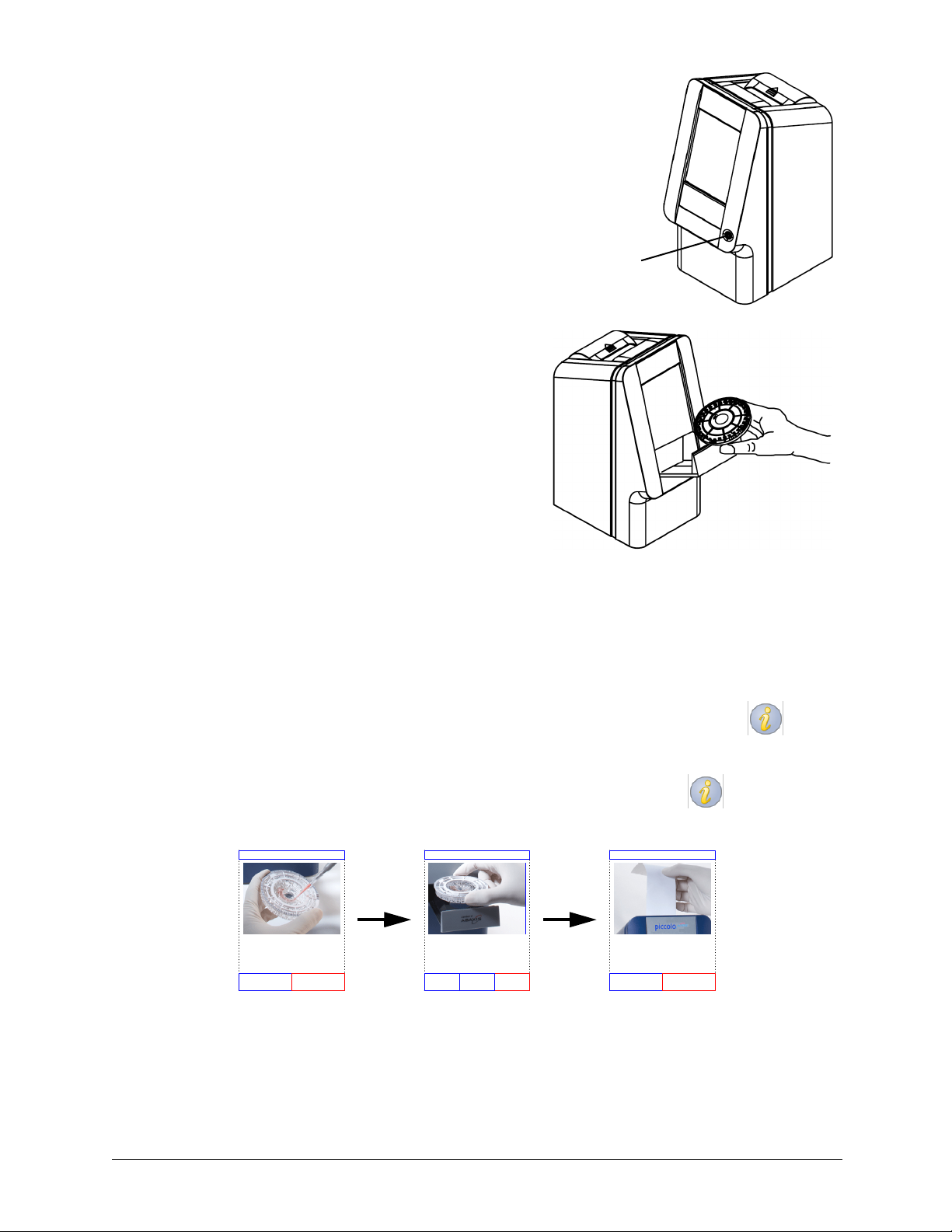
Turn the analyzer’s power on and off by pressing the
Power button on the front of the instrument.
(This button can only turn the power turned off if the
drawer is closed and there is no disc in the analyzer.)
The drawer opens or closes by pressing Analyze or
CLOSE on the touchscreen. Closing a drawer containing
a reagent disc initiates an analysis.
Power button
Results for previously analyzed samples can be accessed using the Recall function — see “Recall-
ing Results” on page 5-1 for instructions.
Information Icons
A number of the piccolo xpress™ touchscreen displays include an information icon that
you can press to get additional information about the procedure you’re performing.
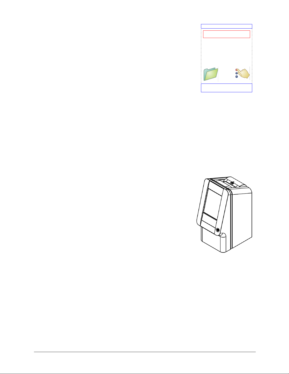
For example, in the screen that appears when you load a disc, you can press to view
screens outlining the basic analysis procedure:
Insert Sam ple
Remove reagent disc from its foil pouch and transfer
100 ul of whole blood, plasma, or serum into the disc.
Exit Next
Insert Disc
Insert the reagent disc into the analyzer, close drawer
and follow on screen prompts.
Back Next
Exit
Press Next and Back to move through the information screens, and Exit to close them.
Read Results
View, read or download results.
Back Exit
2-6 Setup and Description
Page 15

2.6 Reagent Discs
Disc structure and function
In the piccolo® system, all chemistry reactions are performed inside clear plastic reagent discs,
8 cm in diameter and 2 cm thick, specially designed to perform all the steps required to convert a
few drops of whole blood, plasma, or serum into a panel of test results. Each disc contains all the
components and reagents needed to perform one or more tests on a single sample.
A total of 30 cuvettes are located around the periphery:
■ four system cuvettes contain QC reagent beads for
instrument and chemistry quality control
■ a minimum and a maximum absorbance cuvette are
used to calibrate the spectrophotometer
■ a specially designed cuvette detects whether sample
volume was sufficient
■ a cuvette verifies that sufficient diluted sample was delivered to the reaction cuvettes
■ an empty cuvette captures excess fluids
■ 21 cuvettes contain test-specific lyophilized reagent beads.
Bar Code Ring
bar code ring
Cuvettes
cuvettes
Sample Port
sample port
Diluent
diluent
Container
container
Sample Fill Line
sample fill line
The bar code ring attached to the top of the reagent disc contains calibration data for the specific
chemistries in the disc. It also contains the disc identification code, lot number, and expiration
date. The analyzer automatically checks the code and rejects any expired disc. The bar code ring
also protects the optical surfaces of the cuvette from fingerprints and debris, and helps minimize
contamination of the analyzer by capturing small drops of blood that may be on the disc surface.
The sample port, marked by an arrow pointing to a molded circle on the disc’s upper surface,
provides access to the sample chamber. When sufficient sample has been loaded into the sample
chamber, the sample fill line forms between two molded arrows on the disc surface.
A sample diluent is sealed in a container inside the center of the disc. At the beginning of the
reaction cycle, the analyzer opens this container and releases the diluent.
The analyzer separates a lithium-heparinized whole blood sample by centrifugation inside the
disc. Plasma and serum samples are unaffected. Precisely measured quantities of sample and dilu-
ent are delivered to the mixing chamber. Centrifugal and capillary forces then deliver the diluted
sample to the cuvettes, where it dissolves the reagent beads and initiates the chemical reactions.
Reaction products in the cuvettes are then measured photometrically.
Setup and Description 2-7
Page 16

Disc Storage and Handling
CAUTION: Discs are fragile — always handle with care. Do not tap discs on the table or
work bench to empty the sample port. Do not use a disk that has been dropped.
Inspect every reagent disc for damage before use. Never use a damaged disc.
■ Store each reagent disc as described on its label. This keeps the disc’s reagents stable
until the expiration date printed on the disc’s foil pouch and encoded in its bar code
ring. The analyzer automatically rejects any expired disc.
■ Discs can be used directly from the refrigerator (stored at 2–8 °C) without warming.
■ A disc can remain in its sealed pouch at room temperature for a cumulative period of
48 hours. Longer time at room temperature can cause suppression of chemistries and
disc cancellations.
■ Do not expose discs — in or out of their foil pouches — to direct sunlight or to tem-
peratures above 32 °C (90 °F).
■ Inspect the unopened foil pouch for tears and punctures. A torn or damaged pouch
can allow moisture to reach the disc and reduce reagent performance.
■ Open the disc pouch at the notch on the top right edge of the package.
Note: You must use the disc within 20 minutes of opening its pouch.
■ Once the pouch is opened, do not place the disc back in the refrigerator for later use.
■ Keep discs clean. Handle them only by their edges to avoid smudges on the optical
surfaces. Use a lint-free tissue to remove any spilled blood from disc surfaces.
■ Optional: Write the patient identification
number on the disc surface in the space shown
Write patient
ID here
at right. Do not write anywhere else on the
disc, or on the bar code ring.
■ Hold reagent discs flat after introducing the
sample or control to avoid spillage.
WARNING: BIOHAZARD: Used reagent discs contain body fluids. Follow good labora-
tory working practices. Handle all used discs as if they are contaminated
with hepatitis or other infectious diseases. Check with the appropriate state
agency regarding disposal regulations. For more information, see
Section 1.2, “Universal Precautions,” on page 1-1.
2-8 Setup and Description
Page 17

2.7 Ancillary Products
To order consumables or supplies such as reagent discs, pipettes, tips, printer paper, or control
samples, contact your authorized distributor, or call Abaxis Customer Service at 800-822-2947.
Setup and Description 2-9
Page 18

2-10 Setup and Description
Page 19

Section 3
Testing and Results
3.1 Sample Requirements
■ The piccolo xpress™ chemistry analyzer accepts lithium-
heparinized whole blood, plasma, or serum samples.
■ Lithium heparin is the only anticoagulant recommended
for use with the piccolo xpress™.
Note: When collecting the sample in lithium heparin
collection tubes, fill the tube at least half-way
so the anticoagulant does not become too
concentrated in the sample.
■ If using CLIA '88 Waived reagent discs: only lithium-
heparinized whole blood can be used as a sample.
■ If performing a Basic Metabolic Panel Plus: only lith-
ium-heparinized plasma or serum can be used as a sam-
ple. Heparinized whole blood cannot be used.
■ A sample size of 90–120 µL is required.
■ Whole blood must be analyzed within 60 minutes of col-
lection, or separated into plasma or serum.
■ To prevent hemolysis, do not refrigerate or shake whole
blood.
■ If not analyzed immediately, plasma or serum can be
stored at room temperature for no longer than 5 hours
after centrifugation. If storage for more than 5 hours is
required, refrigerate the sample in the stoppered tube at
2–8 °C (36–46 °F) for no longer than 48 hours, or store it
at –10 °C for up to 5 weeks in a freezer with no self-
defrost cycle. Under these conditions, there will be no
clinically important changes in most analyte concentra-
tions.
■ For accurate interpretation of glucose results, the patient
should fast for at least 12 hours before the sample is col-
lected.
Testing and Results 3-1
Page 20

WARNING: Operator health and safety regulations require that Universal Precautions be
observed at all times while handling human blood samples or working with
the piccolo xpress™ chemistry analyzer in any way.
For details, please refer to OSHA 29 CFR Part 1910 (“Occupational Safety
and Health Standards”), Standard Number 1910.1030 (“Toxic and Hazard-
ous Substances: Bloodborne Pathogens”), which can be found on the Inter-
net by going to this address:
http://www.osha.gov
and searching for “1910.1030”.
Note: Operators must also be aware of state and local OSHA biohazard regu-
lations that may specify requirements in addition to the federal regula-
tions, and must also ensure compliance procedures are in place.
3.2 Preparing the Reagent Disc
■ Refer to Section 2.6, “Reagent Discs,” on page 2-7 for complete information about
piccolo® reagent discs, including handling instructions. Make sure you are thor-
oughly familiar with this information before beginning to use the analyzer.
■ Refer to Section 3.1, “Sample Requirements,” on page 3-1 for sample handling
and storage requirements.
Note: Analysis must begin immediately (no more than 10 minutes) after dis-
pensing the sample into the reagent disc.
CAUTION: Discs are fragile — always handle with care. Do not tap discs on the table or
work bench to empty the sample port. Do not use a disk that has been dropped.
Inspect every reagent disc for damage before use. Never use a damaged disc.
3-2 Testing and Results
Page 21
Step 1 — Dispense the Sample
Use a micropipette (one is included with the piccolo xpress™) or other transfer device to dispense
approximately 100 µL of sample into the disc via the sample chamber.
Write patient
ID here
CAUTION: Wear powder-free gloves while handling reagent discs or operating the ana-
lyzer. Powder can disrupt the analyzer’s optical components.
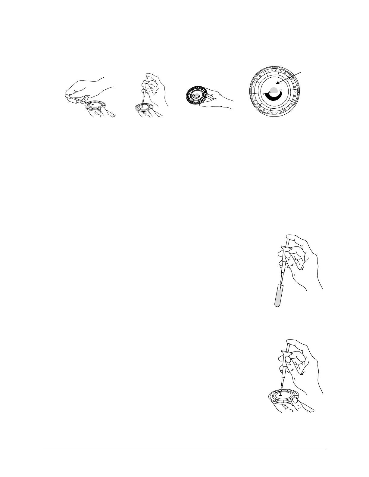
a. Fill the sample chamber.
1. Using the Piccolo 100 µl volume pipette, firmly attach a new tip to the end
of the pipette. DO NOT touch the tip (this could cause a false elevation of
amylase).
2. With your index finger or thumb, push the pipette button to the stop posi-
tion and hold it down for sample pickup.
3. Immerse the tip 2–3 mm below the surface of the sam-
ple, as shown at right.
4. SLOWLY release the button to pick up the sample.
Pause, then remove the pipette from the sample tube.
5. Make sure there are no air bubbles or air gaps in the pipette tip.
6. Place the pipette tip into the disc’s sample chamber,
and tilt the disc to 45° with the sample port above the
fill line, so that the entire sample flows into the sam-
ple chamber. The tip should touch the sample cham-
ber, as shown at right.
Testing and Results 3-3
Page 22

7. Push the plunger down with a slow, continu-
ous motion. Take care not to overfill the
sample chamber. A 90 µL sample will fill
90 μL
the sample chamber and form a line
between the two arrows molded on the disc.
More than 120 µL of sample will overfill
the chamber.
8. Discard the pipette tip into a biohazard con-
tainer.
9. Clean the reagent disc. Use a lint-free tissue to remove any sample spilled
on the outside of the disc, taking care that the tissue does not withdraw any
sample from the sample port. Dispose of the tissue in a biohazard con-
tainer.
b. Optional: Label the disc.
Write the patient ID on the disc surface in the space shown on page 3-3. Do not
write anywhere else on the disc or on the bar code ring.
c. Carry the prepared disc to the analyzer.
> 90 μL
< 120 μL
<90 μL
> 120 μL
Hold the disc by its edges in a flat position.
CAUTION: Do not remove the sample and try to reintroduce it into the disc.
3.3 Running a Patient Sample
This section includes detailed, step-by-step instructions for performing analyses using the
piccolo xpress™.
Note: The analyzer includes a number of optional data functions that can be
used to enter more detailed information about samples.
In this manual, the steps for these optional functions are marked with
the Advanced Setting icon:
The screens for these optional functions appear on the analyzer only if
the functions are enabled. If a screen shown in a procedure step in this
manual does not appear on the analyzer screen, skip that step. (See
“Using Optional Data Functions” on page 4-33 for details about these
functions.)
3-4 Testing and Results
Page 23
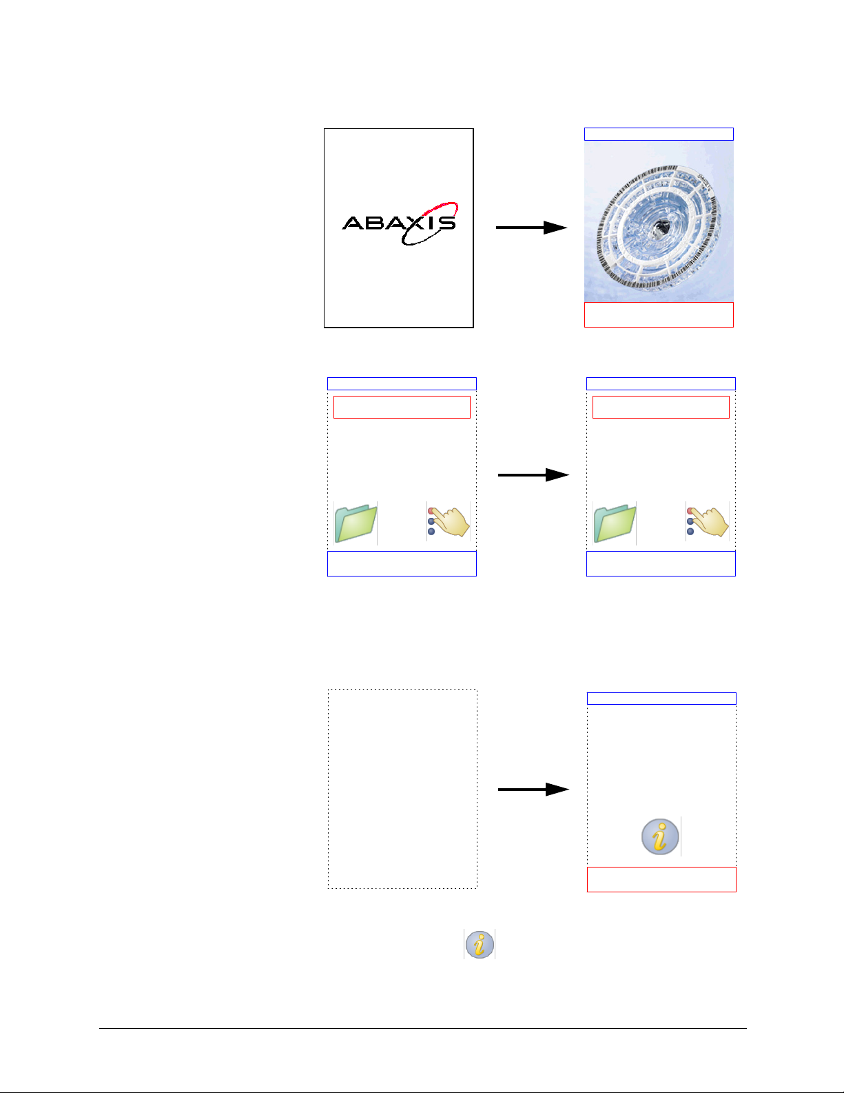
1. Turn on the analyzer by pressing the Power button on the front of the analyzer. Do this
before removing reagent discs from the refrigerator.
The analyzer starts up,
then performs a self
test.
See Section 6.2, “Qual-
ity Control Features”
for information about
the analyzer self test.
If the analyzer needs
time to warm the disc
chamber to operating
temperature, the display
shows “Warming Up.”
When the analyzer
Home
Warming Up
piccolo xpress V1.2.3.4
Performing iQC...
Home
Load Disc
Analyze
Close drawer to
analyze a sample
reaches operating tem-
perature, it displays
Monday 16 Aug 2006 10:30AM
“Analyze” on the Home
screen, as shown at
right.
2. Press Analyze on the touchscreen to open the disc drawer.
The following mes-
sages are then dis-
played:
Opening Drawer...
Monday 16 Aug 2006 10:45AM
CLOSE
Load Disc
Close drawer to
analyze a sample
CLOSE
Note: You can press the information icon in the Load Disc screen to
see help screens outlining the basic analysis procedure. Press Next and
Back to move through the help screens, and Exit to close them.
Testing and Results 3-5
Page 24
3. Place the disc in the recessed area in the drawer.
4. Press CLOSE on the touchscreen. The analyzer then closes the
drawer.
Closing Drawer...
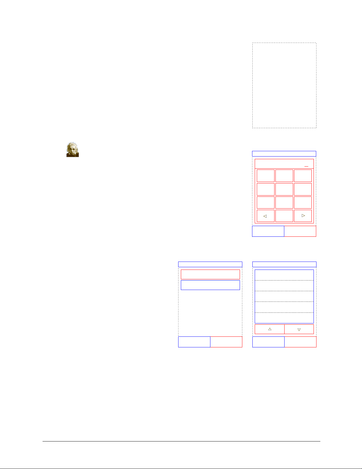
5. Optional: Enter the operator ID using the touchscreen,
then press Done.
The operator ID is a number of up to 14 digits.
The right arrow key ( X) functions as a dash (–), and the left
arrow key (W ) functions as a backspace.
6. Select the sample type from those
shown in the display.
Select Type
Patient
Control
The figure at left shows the default
selections: Patient and Control.
Your actual choices will depend on
how the analyzer is configured —
Enter Operator ID
12345678901234
21 3
4
5 6
7
0
DoneCancel
Select Type
Patient
Control
Control Level 1
Control Level 2
Special 1
98
see “Using Optional Data Func-
tions” on page 4-33.
Note: The correct sample Type is necessary for results to be interpreted cor-
rectly.
3-6 Testing and Results
CancelBack
CancelBack
Page 25
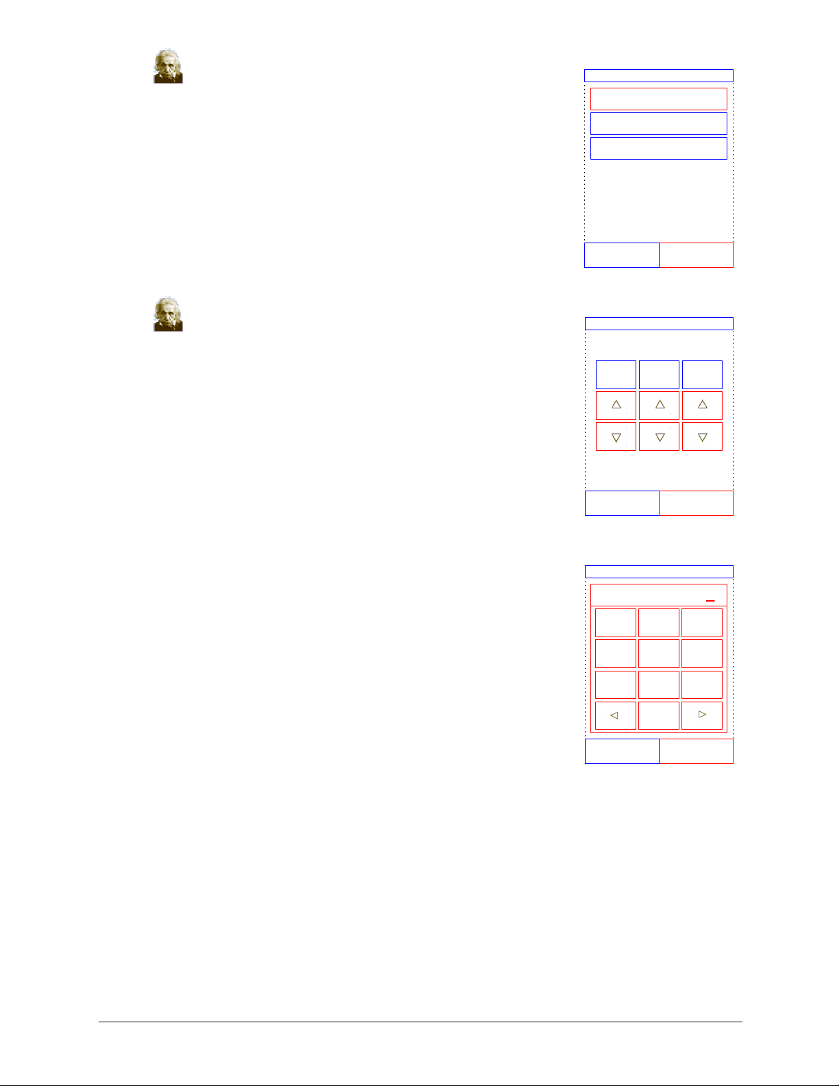
7. Optional: Select the patient’s gender.
Select Gender
Unknown
Male
Female
CancelBack
8. Optional: Enter the patient’s age using the up (S) and
down (T) arrow keys, and adjust the units if needed.
Then press Done.
9. Enter an ID number for the sample (up to 14 characters), then
press Done.
The right arrow key ( X) functions as a dash (–), and the left
arrow key (W ) functions as a backspace.
Enter Age
20 Yrs.
Back Done
Enter Sample ID
12345678901234
21 3
4
7
5 6
98
0
DoneBack
Testing and Results 3-7
Page 26
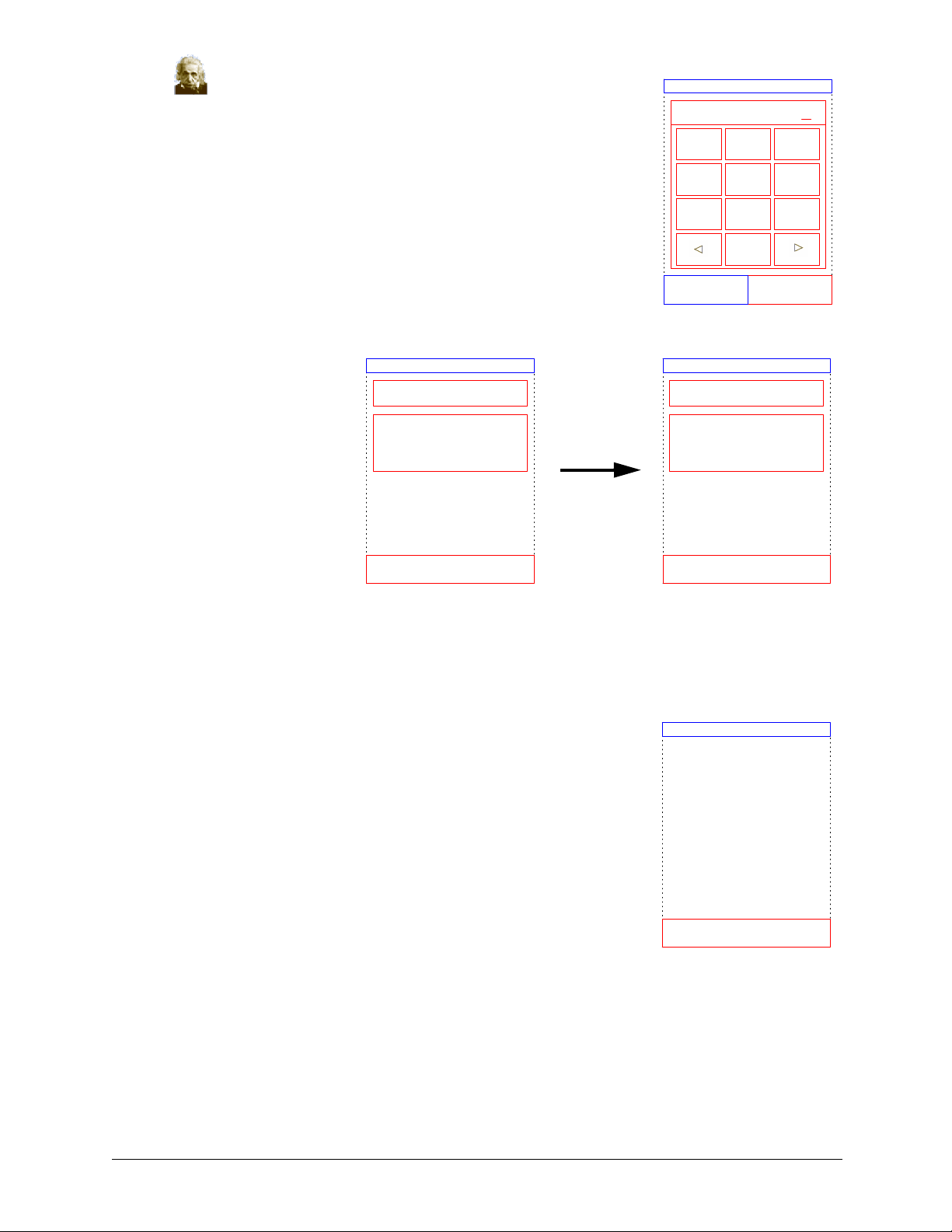
10. Optional: Enter an alternate ID (up to 14 characters),
then press Done.
Enter Alternate Sample ID
12345678901234
21 3
11. The analyzer then
checks the disc type,
and begins processing
the sample.
Sample: 12345678901234
Analyzing Sample...
Determining disc
type...
CANCEL
4
5 6
7
0
DoneBack
Sample: 12345678901234
Analyzing Sample...
Comprehensive
Metabolic Panel
CANCEL
98
Note: If the disc is found to be of an incorrect type or expired, an error mes-
sage appears. Repeat the analysis with another disc of the correct type.
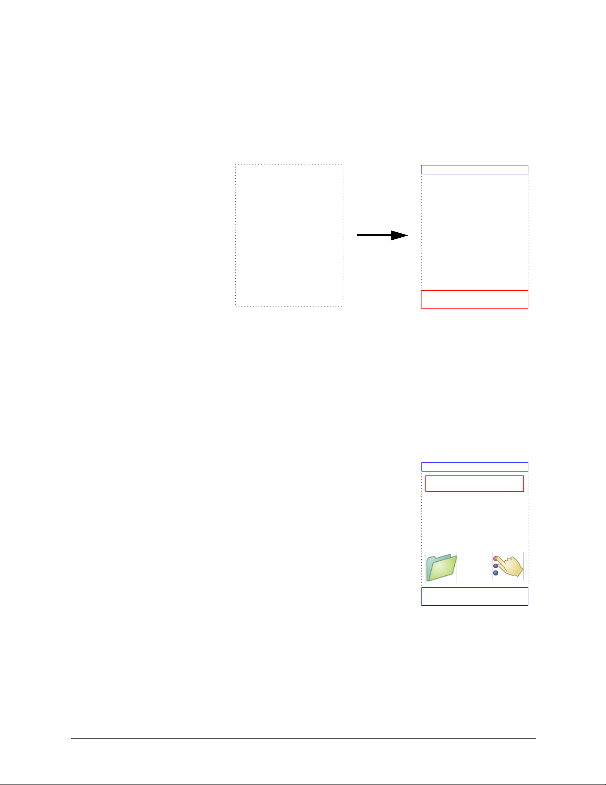
12. When the sample is finished processing, the analyzer stores the
results and shows that the analysis is complete.
Sample: 12345678901234
Analysis Complete
OPEN
3-8 Testing and Results
Page 27
13. By default, the analyzer automatically prints the results of the analysis.
If the results do not print automatically, they can be recalled from memory and printed —
see “Searching for Results” on page 5-3.
Note: Be sure to review the results printout for any suppressed results, which
are marked with these symbols: ~~~
14. Press OPEN to open the
Remove Disc
disc drawer.
Opening Drawer...
To analyze additional sample,
load new disc
CLOSE
15. Remove the reagent disc from the drawer.
CAUTION: Dispose of the disc according to the lab’s standard procedures for human
patient samples. For additional information, see Section 1.2, “Universal Pre-
cautions,” on page 1-1.
16. To analyze another sample, insert the new reagent disc and repeat the above procedure.
17. When finished, press CLOSE to close the drawer and return the
analyzer to standby mode.
Home
Analyze
Monday 16 Aug 2006 10:45AM
Testing and Results 3-9
Page 28
3.4 Canceling Analysis
Occasionally you may need to cancel an analysis in progress. Do this as follows.
1. Press CANCEL on the touchscreen.
The display asks for confirmation.
2. Press CANCEL again to confirm. The analysis is then can-
celed.
Confirm
Cancel Analysis?
Canceling Analysis
Please W ait
NOCANCEL
The disc drawer then
Remove Disc
opens.
Opening Drawer...
To analyze additional sample,
load new disc
CLOSE
3. Remove the disc from the drawer. The analyzer is now ready to perform another analysis.
Press CLOSE to close the drawer.
3-10 Testing and Results
Page 29
3.5 Results
The results calculated by the analyzer are stored in memory and printed automatically, and can
also be recalled and printed later as needed. If the analyzer is connected to an external computer,
the results are automatically transmitted as soon as they are calculated (see Section 10). See
Section 8.2, “Principles of Operation” for the basic procedure and equations used to calculate ana-
lyte concentrations.
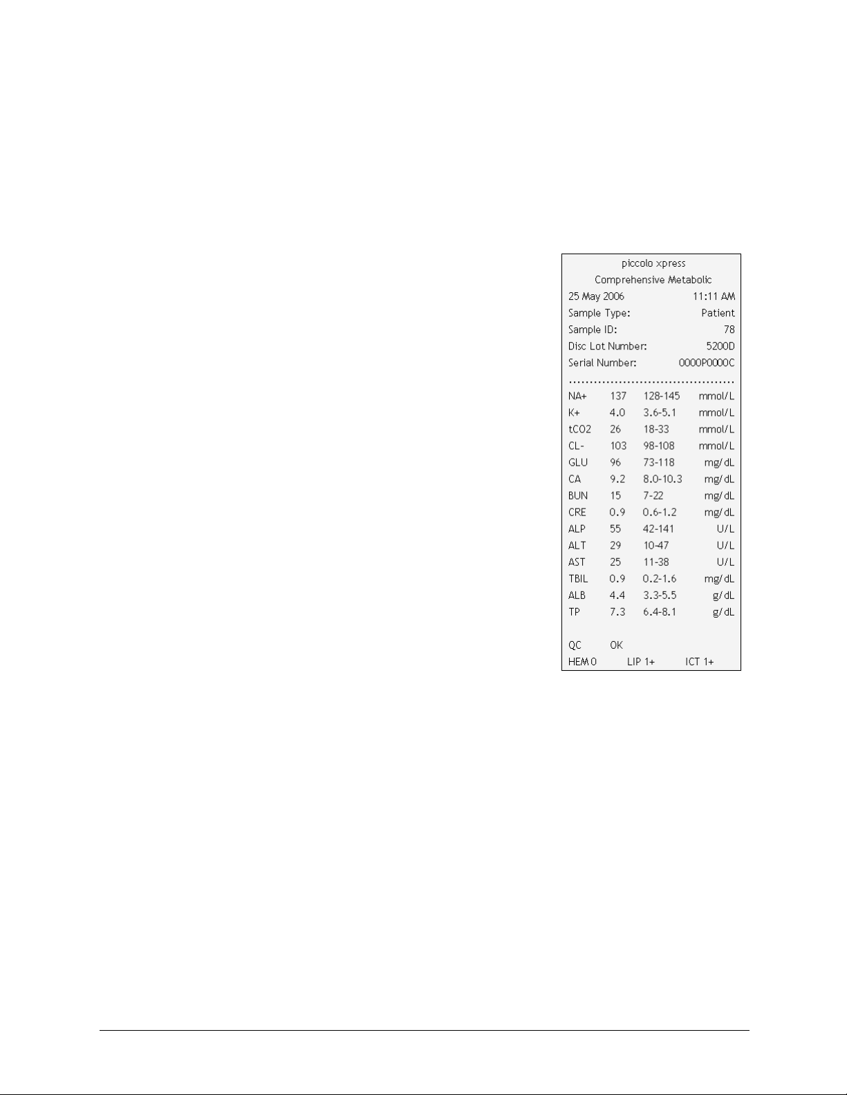
The figure at the right shows the contents of a typical results print-
out. The heading of the results printout includes information such
as the reagent disc type, test date and time, sample type, sample ID
number, alternate ID number, gender, age, operator ID number, disc
lot number, and analyzer serial number. The test results section of
the card is printed in four columns: chemistry name, analyte con-
centration, reference range, and specified units, as shown at right.
The results printout has an adhesive backing so it can easily be
placed into the patient's file.
Each reagent disc contains reagents to detect exposure to extreme
conditions such as temperature and humidity. The message “QC
OK” is printed on the results when results from these reagents are
within the expected ranges. Otherwise, no results are printed, and
the analyzer opens the disc drawer.
■ Results outside the reference range are indicated in
the results by an asterisk (*) printed next to the ana-
lyte concentration.
■ Results outside the dynamic range are indicated in the results by a “less than” sym-
bol (<) printed next to the lowest value of the dynamic range, or a “greater than”
symbol (>) printed next to the highest value of the dynamic range.
For example, the dynamic range of glucose is 10–700 mg/dL. A sample concentra-
tion of glucose below this range would be printed as <10 mg/dL, and a concentra-
tion above this range would be printed as >700 mg/dL. Results outside the
dynamic range should be reported as being below or above the value indicated.
■ The symbols “~~~” are printed in place of numbers when a result cannot be deter-
mined — that is, when the result is suppressed. A result may be suppressed due to
improper mixing of a reagent bead with diluted sample, a nonlinear reaction, an
endpoint of a particular reaction not reached, or a concentration outside the ana-
lyzer’s capabilities. When a chemistry is suppressed (~~~), the analyzer prompts
the operator to print an error report.
Testing and Results 3-11
Page 30

■ For the lactate dehydrogenase (LD) assay only:
Blood cells contain significant levels of LD, and therefore all LD assays are sensi-
tive to hemolysis caused by release of LD from red blood cells. In the following
circumstances, the results are annotated to help interpret LD activity in the pres-
ence of small amounts of hemolysis.
❑ If HEM is greater than 50 and less than or equal to 100 mg/dL, the
printed LD value is followed by an “H” indicating additional influence
from hemolysis.
❑ If HEM is greater than 100 and less than or equal to 150 mg/dL, the LD
value is preceded by “<” and followed by “H”, indicating that the true LD
recovery is less than reported.
❑ If HEM is greater than 150, no result will be indicated and only “HEM”
will be printed.
■ HEM, LIP, or ICT is printed in place of the analyte concentration if hemolysis,
lipemia, or icterus, respectively, has adversely affected the results. LIP is also
printed if both lipemia and icterus have been affected. HEM is also printed if
hemolysis and icterus, hemolysis and lipemia, or hemolysis, lipemia, and icterus
have affected a particular analyte. Examine the sample indices to determine if
more than one interferent is affecting a particular result.
■ The sample indices are included at the bottom of the results printout. These indices
indicate the degree of hemolysis, icterus, and lipemia found in the sample. Hemol-
ysis, icterus, and lipemia are measured on a scale of 0 (clear), 1+ (slight), 2+ (mod-
erate), and 3+ (gross).
If the sample is identified as hemolytic, collect a new sample and run another reagent disc. Abaxis
recommends that the new sample be separated into serum or plasma so that the degree of hemoly-
sis can be verified. If the new sample is hemolytic, use an alternative testing method or send the
sample to a reference laboratory. Samples with hematocrit in excess of 60% packed red cell vol-
ume may appear on the result card as HEM. Follow the instructions above for retesting hemolyzed
samples.
High lipemia may be due to diet. Ensure the patient has fasted for at least 12 hours before collect-
ing another sample. For suggestions on testing grossly lipemic or icteric samples, see “Trouble-
shooting” on page 7-1. For grossly lipemic samples from fasting patients or for icteric samples,
use an alternative testing method or send the sample to a reference laboratory.
3-12 Testing and Results
Page 31

3.6 Testing Procedure Summary
piccolo xpress™ Chemistry Analyzer
■ Check that the electrical outlet utilized for the analyzer is grounded.
■ Check that the ambient temperature where the analyzer is located is 15–32 ºC
(59–90 ºF).
■ Do not disconnect the power to the analyzer while running a sample.
■ Keep the analyzer drawer closed when not in use.
■ Do not attempt to repair the analyzer; this may void the warranty. Refer to
Section 7 for troubleshooting and Section 9 for regular maintenance.
Reagent Discs
CAUTION: Discs are fragile — always handle with care. Do not tap discs on the table or
work bench to empty the sample port. Do not use a disk that has been dropped.
Inspect every reagent disc for damage before use. Never use a damaged disc.
■ Do not use an expired disc. The reagent disc expiration date is printed on the foil
pouch and is encoded in the bar code.
■ Store all reagent discs at 2–8 ºC (36–46 ºF) as described on their respective pouch
labels. Discs may be used directly from the refrigerator.
■ Keep reagent discs clean. Use powder-free gloves to handle the discs, and touch
the discs only along their edges to eliminate the possibility of fingerprints on the
cuvette optical surfaces. If sample spills on the outside of the disc, remove it with a
lint-free tissue, and make sure the tissue does not withdraw any sample from the
sample port.
■ After introducing the sample, hold the reagent disc flat to avoid spillage.
■ Never use a reagent disc that has been dropped.
■ Use the reagent disc within 20 minutes of opening the foil pouch.
■ Run the reagent disc within 10 minutes of applying the sample.
Testing and Results 3-13
Page 32

Samples
■ Analyze whole blood samples within 60 minutes of collection.
■ Fill the lithium heparin specimen collection tube at least half-way to ensure the
sample does not have a high concentration of anticoagulant.
■ To prevent hemolysis, do not refrigerate or shake whole blood samples.
■ When adding blood to evacuated collection tubes, remove the needle from the
syringe and the stopper from the tube, and gently place the sample into the tube.
(If sample is injected through the stopper, hemolysis may occur.)
CAUTION: Do not remove a sample and then try to reintroduce it into the disc.
Note: Always fill evacuated collection tubes in this order: Red, then Green,
then Lavender.
3-14 Testing and Results
Page 33

Section 4
Configuring the
Analyzer
This section describes how to configure the piccolo xpress™ chemistry
analyzer to achieve excellent performance.
Here are the main analysis tasks:
■ See “Using the Settings Screens” on page 4-2 for an overview on
making settings for the analyzer.
■ Change reference ranges to be specific to the patient population,
and print, transmit, or archive these ranges.
❑ “Customizing Reference Ranges” on page 4-2
❑ “Printing and Archiving Reference Ranges” on page 4-12
❑ “Transmitting Reference Ranges” on page 4-16
■ Change general analyzer settings.
❑ “Viewing Analyzer Identification” on page 4-17
❑ “Changing Date and Time” on page 4-18
❑ “Selecting the Language” on page 4-19
❑ “Selecting Units” on page 4-20
❑ “Setting Sound Volumes” on page 4-24
❑ “Adjusting the Display” on page 4-25
❑ “Printer Settings” on page 4-28
❑ “Setting Communication Protocol” on page 4-32
❑ “Using Optional Data Functions” on page 4-33
■ Run control samples — see “Running Controls” on page 4-34.
Configuring the Analyzer 4-1
Page 34

4.1 Using the Settings Screens
The following shows the general path through the analyzer’s menus for performing the procedures
in this section. These procedures are available whenever the analyzer displays the Home screen.
1. In the Home screen, press the Settings icon.
The Analyzer Settings screen then appears. From here, adjust the date and
time, language, sound, display, and printer, or view basic information about
the analyzer.
2. Press the More Settings icon.
This opens the second Analyzer Settings screen. Use this screen as a starting
point to make additional settings, work with reference ranges, and update the
analyzer’s software.
3. Press Home to return to the analyzer’s Home screen.
4.2 Customizing Reference Ranges
The piccolo xpress™ includes a number of factory-set analyte and demographic reference ranges
for use in analysis. You can modify these ranges as needed, as well as create or remove custom
ranges, or return all factory ranges to their default settings.
Note: Change reference ranges in either Common units or SI units, not both.
The analyzer automatically converts units.
1. In the Home screen, press the Settings icon.
2. Press the More Settings icon.
3. Press the Reference Range Settings icon.
4-2 Configuring the Analyzer
Page 35

4. Select the reference range to modify:
Include Reference Ranges
■ To modify the last reference range that was changed,
press Last Modified, then skip to step 5 on page 4-5.
■ To modify any reference range, press All, then continue
with the next step below.
Note: Press the information icon for additional
help.
5. The Modify Reference Ranges screen then opens. From here,
the following procedures are available:
■ Modify the reference ranges for a specific analyte —
see below.
■ Modify the reference ranges for a particular demo-
graphic — see page 4-5.
■ Add a reference range for a new demographic —
see page 4-7.
Last Modified: ALB
All
Back Home
Modify Reference Ranges
Analyte
Demographic
Back Home
■ Remove a reference range for a demographic — see
page 4-10.
■ Return all factory reference ranges to their default values — see page 4-11.
Modifying Reference Ranges for an Analyte
Change the reference ranges for a specific analyte as follows.
1. In the Modify Reference Ranges screen, press Analyte.
Note: Press the information icon for additional
help.
Modify Reference Ranges
Analyte
Demographic
Back Home
Configuring the Analyzer 4-3
Page 36

2. In the Analyte List screen, select the analyte.
Use the up (S) and down (T) arrow keys as needed to scroll
through the list.
AnalyteList
ALB
ALP
ALT
AMY
AST
HomeBack
3. Select the patient’s gender.
4. Select the reference range to modify.
Use the up (S) and down (T) arrow keys as needed to scroll
through the list.
Select Gender
Male AL B Range s
3.3 - 5.5 g/dL
Patient
3.3 - 5.5
Control
3.3 - 5.5
Cntl. 1
Cntl. 2
3.3 - 5.5
Cntl. 3
3.3 - 5.5
Unknown
Male
Female
HomeBack
g/dL
g/dL
g/dL
g/dL
4-4 Configuring the Analyzer
HomeBack
Page 37

5. Use the controls to set the upper and lower limits for the range.
■ Use the up (S) and down (T) arrow keys to adjust the
values.
■ Press Clear to set both limits to zero.
■ Press Default to use the factory default values for the
ALB Patient [g/dL]
Lower
Upper
3.3 5.5
range.
6. Press Save to store the changes.
Clear Default
SaveCancel
Modifying the Reference Ranges for a Demographic
Use this procedure to modify the reference ranges for a particular demographic, patient type, or
control.
1. In the Modify Reference Ranges screen, press Demographic.
Note: Press the information icon for additional
help.
Modify Reference Ranges
Analyte
Demographic
Back Home
2. In the Demographics screen, choose the patient or control
demographic to modify.
Use the up (S) and down (T) arrow keys as needed to scroll
through the list.
Configuring the Analyzer 4-5
Demographics
Add Demographic
Remove Demographic
Factory Default Demographics
Patient
Control
HomeBack
Page 38

3. Patient demographic only: select the gender.
Select Gender
Unknown
Male
Female
HomeBack
4. The analyzer then displays the
ranges for the patient or control
demographic.
Select the analyte to adjust. If
needed, use the up (S) and
down (T) arrow keys to scroll
through the list.
5. Use the controls to set the upper and
lower limits for the range.
■ Use the up (S) and down
(T) arrow keys to adjust the
values.
■ Press Clear to set both limits
to zero.
Female Patient Ranges
ALB 3.3 - 5.5
ALP
42 - 141
ALT
10 - 47
AMY
14 - 97
AST
11 - 38
ALB Patient [g/dL]
Lower
3.3 5.5
Clear Default
HomeBack
Upper
g/dL
U/L
U/L
U/L
U/L
Contr ol Ranges
ALB 0.0 - 0.0
ALP
0 - 0
ALT
0 - 0
AMY
0 - 0
AST
0 - 0
ALB Control [g/dL]
Lower
0.0 0.0
Clear Default
g/dL
U/L
U/L
U/L
U/L
HomeBack
Upper
■ Press Default to use the fac-
tory default values for the
range.
6. Press Save to store the changes.
4-6 Configuring the Analyzer
SaveCancel
SaveCancel
Page 39

Adding a Demographic
Use this procedure to add reference ranges for a particular demographic.
1. In the Modify Reference Ranges screen, press Demographic.
Note: Press the information icon for additional
help.
2. In the Demographics screen, press Add Demographic.
Modify Reference Ranges
Analyte
Demographic
Back Home
Demographics
Add Demographic
Remove Demographic
Factory Default Demographics
Patient
Control
■ To create a reference range for a new, unnamed demographic:
a. Press Special #.
(Press the information icon for additional
help.)
Note: The displayed number # depends on the number of
special or control level demographics that have
already been added or deleted.
HomeBack
Add Demographic
Special #
Control Level #
Back Home
Configuring the Analyzer 4-7
Page 40

b. Select the gender.
Select Gender
Unknown
Male
Female
HomeBack
c. Set minimum and maximum values for each of the
analytes to be included in the range:
i. Select the analyte to adjust. If needed, use the
up (S) and down (T) arrow keys to scroll
through the list.
ii. Use the control values to set upper and lower
limits for the analyte.
❑ Use the up (S) and down (T) arrow
keys to adjust the values.
Note: Entering zero for both values suppresses printing of
the ranges for this analyte in results (blanks appear
instead), and also suppresses checking the
recovered value against the range limits.
Unknown Spe cia l 1 Range s
ALB 0.0 - 0.0
ALP
0 - 0
ALT
0 - 0
AMY
0 - 0
AST
0 - 0
ALB Special 1 [g/dL]
Lower
0.0 0.0
Clear Default
g/dL
U/L
U/L
U/L
U/L
HomeBack
Upper
SaveCancel
❑ Press Clear to set both limits to zero.
❑ Press Default to use the factory default values for the range.
d. Press Save to store the changes.
4-8 Configuring the Analyzer
Page 41

■ To create a new control:
a. Press Control Level #.
(Press the information icon for additional
help.)
b. Set minimum and maximum values for each of the
analytes to be included in the range:
i. Select the analyte to adjust from the list. If
needed, use the up (S) and down (T) arrow
keys to view the entire list.
Add Demographic
Special #
Control Level #
Back Home
Control n Ranges
0.0 - 0.0 g/dL
ALB
0 - 0
ALP
0 - 0
ALT
0 - 0
AMY
U/L
U/L
U/L
ii. Use the controls to set upper and lower limits
for the analyte.
❑ Use the up (S) and down (T) arrow
keys to adjust the values.
Note: Entering zero for both values suppresses printing of
the ranges for this analyte in results (blanks appear
instead), and also suppresses checking the recovered
value against the range limits.
❑ Press Clear to set both limits to zero.
❑ Press Default to use the factory default values for the range.
AST
0 - 0
ALB Control n [g/dL]
Lower
0.0 0.0
Clear Default
U/L
HomeBack
Upper
SaveCancel
c. Press Save to store the changes.
Configuring the Analyzer 4-9
Page 42

Removing a Demographic
Use this procedure to remove the reference ranges for a particular demographic.
1. In the Modify Reference Range screen, press Demographic.
Note: Press the information icon for additional
help.
2. In the Demographics screen, press Remove Demographic.
Modify Reference Ranges
Analyte
Demographic
Back Home
Demographics
Add Demographic
Remove Demographic
Factory Default Demographics
Patient
Control
3. Select the demographic to remove. Use the up (S) and down
(T) arrow keys to scroll through the list.
HomeBack
Remove Demographic
Patient
Control
Control Level 1
Special 1
Special 2
HomeBack
4-10 Configuring the Analyzer
Page 43

4. A warning screen then appears. Press Continue to permanently
remove the demographic.
WARNING
(Press the information icon for additional help.)
Control Level 1 will be
removed from Type list
Continue
Restoring Factory Default Demographics
Use this procedure to restore all factory reference ranges to their default settings.
1. In the Modify Reference Ranges screen, press Demographic.
Note: Press the information icon for additional
help.
Modify Reference Ranges
CANCEL
Analyte
Demographic
2. In the Demographics screen, press Factory Default Demo-
graphics.
Back Home
Demographics
Add Demographic
Remove Demographic
Factory Default Demographics
Patient
Control
HomeBack
Configuring the Analyzer 4-11
Page 44

3. Press Ye s .
Factory Default Demographics
Pres Yes to return all
reference Range Settings to
factory defaults
HomeBack Yes
4.3 Printing and Archiving Reference Ranges
Reference ranges can be printed, or stored in the analyzer as archive files for later use or review.
1. In the Home screen, press the Settings icon.
2. Press the More Settings icon.
3. Press the Archive Reference Ranges icon.
4. Press Send.
Note: Press the information icon for additional
help.
Archive Reference Ranges
Send
Retrieve
Back Home
4-12 Configuring the Analyzer
Page 45

■ To archive the reference ranges into the analyzer’s inter-
nal memory: press Internal Archive.
The reference range is then stored in the analyzer under
Send Reference Ranges
Printer
Internal Archive
External Archive
the current date and time.
(Press the information icon for additional help.)
Back Home
Note: See “Retrieving Reference Ranges” for instructions on retrieving stored
archives.
■ To archive the ranges onto a PC connected to the analyzer, see page 4-16.
(See page 10-1 for instructions on connecting a PC to the analyzer.)
■ To print a range or ranges:
a. Press Printer.
(Press the information icon for additional
help.)
b. Select the report type
Select Report
to print (the left dia-
gram shows the default
choices, the right
Patient
shows typical custom-
Control
ized choices).
All
Send Reference Ranges
Printer
Internal Archive
External Archive
Back Home
Select Report
All
Patient
Control
Special 1
Special 2
All prints controls and
patients.
Configuring the Analyzer 4-13
Back Home
HomeBack
Page 46

c. The reference range (or ranges) is then printed.
4.4 Retrieving Reference Ranges
Reference ranges can be retrieved from archives as follows.
Note: Retrieving an archived reference range overwrites all reference range
values currently in the analyzer. Consider archiving the current
reference ranges before retrieving another set.
Sending Report...
1. In the Home screen, press the Settings icon.
2. Press the More Settings icon.
3. Press the Archive Reference Ranges icon.
4-14 Configuring the Analyzer
Page 47

4. Press Retrieve.
Archive Reference Ranges
Note: Press the information icon for additional
help.
5. Select the archive to retrieve. Use the up (S) and down (T)
arrow keys as needed to scroll through the list.
Send
Retrieve
Back Home
Internal Archives
31 Aug 2006 10:01 AM
31 Jul 2006 12:01 PM
23 Jun 2006 7:01 AM
31 May 2006 3:15 PM
20 Apr 2006 10:10 AM
6. A warning screen then appears. Press Continue to retrieve the
archived reference range.
(Press the information icon for additional help.)
Back
WARNING
Restoring Reference Ranges
to 23 Jun 2006 12:01 PM
Continue
Home
CANCEL
Configuring the Analyzer 4-15
Page 48

4.5 Transmitting Reference Ranges
Reference ranges can be transmitted to a connected PC and stored for later use or review.
1. In the Home screen, press the Settings icon.
2. Press the More Settings icon.
3. Press the Archive Reference Ranges icon.
4. Press Send.
Note: Press the information icon for additional
help.
5. Press External Archive.
(Press the information icon for additional help.)
Archive Reference Ranges
Send
Retrieve
Back Home
Send Reference Ranges
Printer
Internal Archive
External Archive
4-16 Configuring the Analyzer
Back Home
Page 49

6. Select the report type (the type of
ranges) to send to the PC.
Select Report
All
Select Report
All
Patient
Control
Back Home
The reference range is then sent to the PC and stored under the
current date and time.
Patient
Control
Special 1
Special 2
HomeBack
Sending Report...
Note: See “Retrieving Reference Ranges” for instructions on retrieving stored
archives.
4.6 Viewing Analyzer Identification
Use this function to verify information about the analyzer, such as its serial number, the version of
the installed software, and information about the tests that have been run and printed.
1. In the Home screen, press the Settings icon.
2. Press the Analyzer Information icon.
Configuring the Analyzer 4-17
Page 50

3. The display then shows the analyzer information.
Analyzer Information
Name: piccolo xpress
Serial No.: 0000P00077
Version: 2.1.1
HomeBack
4.7 Changing Date and Time
The date and time is factory preset to Pacific Time. Verify the date and time when the analyzer is
removed from its shipping carton.
1. In the Home screen, press the Settings icon.
2. Press the Date and Time icon.
3. In the Set Time screen, use the controls to set the time:
■ Use the up (S) and down (T) arrow keys to adjust
the hour and minutes.
■ Press 12/24 Hour to switch between 12- and 24-hour
time formats.
■ Press Zero Sec. to set the seconds to zero.
4. Press Date when the time is set.
Note: If the time entered is invalid, an error message appears — press
Continue, set the correct time, then press Done.
Set Time
10:15:00 AM
Hour Minute
12/24 Hour Zero Sec.
Date
4-18 Configuring the Analyzer
Page 51

5. In the Set Date screen, use the up and down arrow keys to adjust
Set Date
the day, month, and year.
Day Month Year
6. Press Done when the date is set.
AUG27 06
Note: If the date entered is invalid, an error message
appears — press Continue and set the correct date.
Done
4.8 Selecting the Language
The analyzer provides several languages for menus, the keyboard, and printing. Select the lan-
guage to use (English USA is the default) as follows.
1. In the Home screen, press the Settings icon.
2. Press the Languages icon.
3. Select the display language from the list. If needed, use the up
(S) and down (T) arrow keys to view the entire list.
Select Display Language
English (USA)
Français
Deutsch
Italiano
Español
Back Home
Configuring the Analyzer 4-19
Page 52

4. Select the keyboard type from the list. Use the up (S) and
down (T) arrow keys to scroll through the list.
Select Keyboard Type
English (USA)
Françai s
Deutsch
Italiano
Español
Back Home
4.9 Selecting Units
Use this procedure to set the units used by the analyzer and in results: Common units (mg/dL,
etc.) or SI units (Systeme International) (mmol/L, etc.).
1. In the Home screen, press the Settings icon.
2. Press the More Settings icon.
3. Press the Units Settings icon.
4. Set the units used for all analytes, a particular analyte, or a group of analytes as follows.
■ To set units for all analytes:
a. Press All Analytes.
Set Units
All Analytes
Analyte Groups
Single Analyte
4-20 Configuring the Analyzer
Back Home
Page 53

b. Select the units to use for all analytes:
Non SI or SI.
All Units
Non SI
Note: Press the information icon for additional
help.
■ To set the units for a particular analyte:
a. Press Single Analyte.
SI
Back Home
Set Units
All Analytes
Analyte Groups
Single Analyte
Back Home
b. Select the analyte from the list.
Use the up (S) and down (T) arrow keys as
needed to scroll through the list.
ALB
ALP
ALT
AMY
AST
Back
Single Unit
Home
Configuring the Analyzer 4-21
Page 54

c. Select the units to use for the analyte: g/dL, g/L,
mg/dL, mg/L, or umol/L.
ALB Units
g/dL
g/L
mg/dL
mg/L
umol/L
Back Home
■ To set units for a group of analytes (electrolytes, enzymes, lipids, minerals, or pro-
teins):
a. Press Analyte Groups.
b. Press to select the analyte group: Electrolytes,
Enzymes, Lipids, Minerals, or Proteins.
Set Units
All Analytes
Analyte Groups
Single Analyte
Back Home
Group Units
Elec trolytes
Enzymes
Lipids
Minerals
Prot eins
4-22 Configuring the Analyzer
Back Home
Page 55

■ For electrolytes: select mmol/L or mEq/L.
Electrolyte Units
mmol/L
mEq/L
Back Home
■ For enzymes: select U/L or ukat/L.
■ For lipids: select mg/dL or mmol/L.
Enzym es Units
U/L
ukat/L
Back Home
Lipids Units
mg/dL
mmol/L
Back Home
Configuring the Analyzer 4-23
Page 56

■ For minerals: select mg/dL, mmol/L,
or mEq/L.
Minerals Units
mg/dL
mmol/L
mEq/L
Back Home
■ For proteins: select g/dL or g/L.
Proteins Units
g/dL
g/L
Back Home
4.10 Setting Sound Volumes
Use this procedure to adjust the volume of the sounds used for the analyzer’s screen click, alert,
and status notification.
1. In the Home screen, press the Settings icon.
2. Press the Sound Settings icon.
4-24 Configuring the Analyzer
Page 57

3. Select the sound to adjust.
Sound Settings
Note: Press the information icon for additional
help.
4. Use the controls to set the selected volume.
■ Use the up (S) and down (T) arrow keys to adjust
the volume.
■ Press Off to turn the sound off.
■ Press Default to set the sound to its factory default
value.
Screen Clic k
Alerts
Status
Back Home
Click Volume
Current
80%
Off
Default
New
80%
HomeBack Save
5. Press Save to store the new setting.
4.11 Adjusting the Display
The brightness of the analyzer’s display can be adjusted as needed, and the display’s touchscreen
can be calibrated for best performance. In addition, the time the analyzer must be inactive before
it activates a screen saver or enters power-saving mode can be set as required. (For either, touch
the screen to wake the analyzer.)
1. In the Home screen, press the Settings icon.
2. Press the Display Settings icon.
Configuring the Analyzer 4-25
Page 58

3. Adjust or calibrate the display as follows.
■ To adjust the backlight brightness:
a. Press Back Light.
(Press the information icon for additional
help.)
b. Use the controls to set the brightness:
❑ Use the up (S) and down (T) arrow keys to
adjust the brightness level.
❑ Press Full to select maximum brightness.
❑ Press Default to set the brightness to its fac-
tory default.
Display Settings
Back Light
Screen Saver
Power Save
Calibrate
Back Home
Backlight Brightness
Current
90%
Full
Default
New
70%
c. Press Save to store the new setting.
■ To adjust the screen saver delay:
a. Press Screen Saver.
(Press the information icon for additional
help.)
HomeBack Save
Display Settings
Back Light
Screen Saver
Power Save
Calibrate
Back Home
4-26 Configuring the Analyzer
Page 59

b. Use the controls to set the delay.
❑ Use the up (S) and down (T) arrow keys
to adjust the delay.
Screen Saver Wait
Current
Never
New
15 min
❑ Press Never to turn off the screen saver.
❑ Press Default to set the delay to its factory
default.
c. Press Save to store the new setting.
■ To adjust power-saving delay:
a. Press Power Save.
(Press the information icon for additional
help.)
Never
Default
HomeBack Save
Display Settings
Back Light
Screen Saver
Power Save
Calibrate
Back Home
b. Use the controls to set the delay.
❑ Use the up (S) and down (T) arrow keys to
adjust the delay.
❑ Press Never to prevent the analyzer from
entering power-saving mode.
❑ Press Default to set the delay to its factory
default.
c. Press Save to store the new setting.
Power Save Wait
Current
Never
Never
Default
HomeBack Save
New
30 min
Configuring the Analyzer 4-27
Page 60

■ To calibrate the display’s touchscreen:
a. Press Calibrate.
(Press the information icon for additional
help.)
b. Press Ye s to start the calibration process, and fol-
low the on-screen instructions.
(Press the information icon for additional
help.)
Display Settings
Back Light
Screen Saver
Power Save
Calibrate
Back Home
Calibrate Touch Screen
Press Yes to start
HomeBack Yes
4.12 Printer Settings
Use the procedures in these pages to set up and configure the analyzer’s internal printer, or an
external printer connected to the analyzer.
1. In the Home screen, press the Settings icon.
2. Press the Printer Settings icon.
4-28 Configuring the Analyzer
Page 61

3. The Printer Setup screen is then displayed.
Printer Setup
■ To select the default printer to be used with the analyzer,
see “Setting the Default Printer” below.
Configure
Test
■ To test a printer for proper function, see “Testing a
Printer” on page 4-30.
■ To select which reports can be printed automatically
after an analysis, see “Selecting Reports” on page 4-31.
Back Home
Note: Press the information icon for additional help.
Setting the Default Printer
This procedure selects the printer that the analyzer will use for printing results and reports.
1. In the Printer Setup screen, press Configure.
Note: Press the information icon for additional
help.
Printer Setup
Configure
Test
2. Press Set Default.
(Press the information icon for additional help.)
Back Home
Configure Printer
Set Default
Select Reports
Back Home
Configuring the Analyzer 4-29
Page 62

3. Select the Analyzer Printer or an External Printer.
Set Default
Analyzer Printer
External Printer
Back Home
4. External Printer only: select the printer from the displayed list of available printers.
The analyzer then detects automatically detects the type of printer and configures it as
needed.
Testing a Printer
Test the function of the analyzer’s printer or a connected external printer as follows.
1. In the Printer Setup screen, press Test.
Note: (Press the information icon for additional
help.)
2. Select the printer to test.
The selected printer then outputs a test page.
Printer Setup
Configure
Test
Back Home
Select Printer
Analyzer P rinter
External Printer
4-30 Configuring the Analyzer
Back
Home
Page 63

Selecting Reports
Use this procedure to set the type and number of reports that can be printed automatically after a
sample is analyzed.
1. In the Printer Setup screen, press Configure.
Note: Press the information icon for additional
help.
2. Press Select Reports.
(Press the information icon for additional help.)
Printer Setup
Configure
Test
Back Home
Configure Printer
Set Default
Select Reports
3. Select the report type.
(Press the information icon for additional help.)
Back Home
Select Reports
Results: 1
iQC: 0
Errors: 1 Auto
Back Home
Configuring the Analyzer 4-31
Page 64

4. Use the controls to adjust the number of copies to print:
■ Use the up (S) and down (T) arrow keys to adjust the
number.
# Results Copies
Current
1
New
2
■ Press Clear to set the number to zero.
■ Press Default to use the factory default value.
5. Press Save to store the new setting.
Clear
Default
HomeBack Save
4.13 Setting Communication Protocol
To transmit results and other information from the analyzer to an external computer, specify the
communication protocol to be used.
1. In the Home screen, press the Settings icon.
2. Press the More Settings icon.
3. Press the Communication Settings icon.
4. Select a protocol: ASCII Text, ASTM E-1394-97, or None.
Note: Press the information icon for additional
help.)
4-32 Configuring the Analyzer
Set Protocol
None
ASCII Text
ASTM E-1394-97
Back Home
Page 65

4.14 Using Optional Data Functions
The piccolo xpress™ includes a number of optional data-entry functions that can be used to enter
more detailed information about samples, such as age and gender. The analyzer can be configured
to use some or all of these functions as needed.
Note: The analyzer includes a number of optional data functions that can be
used to enter more detailed information about samples.
In this manual, the steps for these optional functions are marked with
the Advanced Setting icon:
The screens for these optional functions appear on the analyzer only if
the functions are enabled. If a screen shown in a procedure step in this
manual does not appear on the analyzer screen, skip that step. (See
“Using Optional Data Functions” on page 4-33 for details about these
functions.)
1. In the Home screen, press the Settings icon.
2. Press the More Settings icon.
3. Press the Advanced Settings icon.
Configuring the Analyzer 4-33
Page 66

4. In the Advanced Settings screen, select the types of information
that will need to be entered during the analysis process.
Advanced Settings
Operator ID
Alternate ID
Gender
Age
HomeBack
5. Alternate ID only: select an alternate ID item to be entered
(such as Doctor ID, Phone #, DOB, Admission ID, and
Patient ID).
Alternate ID
Disabled
Alternate ID
Doctor ID
Use the up (S) and down (T) arrow keys to scroll through the
list.
Phone Number
DOB
DisableBack Enable
4.15 Running Controls
A control is a biological sample or solution with a suitably contrived matrix that is analyzed for
purposes of quality control. The composition of the matrix must be such that the solution closely
matches that of the biological specimen for characteristics of importance to the analyzer. Control
materials need to be stable and available in sufficient volumes in multiple portions and over an
extended period. Many control products are available commercially. Assayed controls also come
with expected values of the analytes for guidance.
Abaxis recommends control testing as follows:
■ at least every 30 days
■ whenever laboratory conditions have changed significantly
■ when training or retraining of personnel is indicated
■ when test results do not match patient symptoms or clinical findings
Good laboratory practices include the recording of the QC data according to the laboratory’s
established written procedures. A permanent record of control results should be retained.
4-34 Configuring the Analyzer
Page 67

Samples and controls are run identically by the analyzer. However, using the Run Controls option
in the Menu function stores control results separately from patient results in the analyzer memory.
Control results can be printed on a result card immediately after the conclusion of the control run,
or whenever the control run results are recalled. (See Section 5 for information on using the
RECALL key.) Control results are automatically transmitted to a linked computer.
Handle the control as described in the control package insert. Call Abaxis Technical support for
assistance in interpreting control results.
The analyzer automatically stores control results in a memory separate from the patient results
memory. The Recall function can be used to search for specific control results without searching
through all patient results stored in memory.
Note: Before a control can be run, a control level must be enabled in the
reference ranges — see page 4-9.
Controls can be run whenever the analyzer displays the Home screen.
Note: For more details on running controls, see “Preparing the Reagent Disc”
on page 3-2.
CAUTION: Discs are fragile — always handle with care. Do not tap discs on the table or
work bench to empty the sample port. Do not use a disk that has been dropped.
Inspect every reagent disc for damage before use. Never use a damaged disc.
1. In the Home screen, press Analyze to open the disc drawer.
Monday 16 Aug 2006 10:45AM
Home
Analyze
Configuring the Analyzer 4-35
Page 68

2. Place the disc in the drawer, then press CLOSE to close the
drawer and start analysis.
Load Disc
Analysis then begins.
Note: Press the information icon for additional
help.
3. Optional: Enter the Operator ID, then press Done.
The right arrow key ( X) functions as a dash (–), and the
left arrow key (W ) functions as a backspace.
Note: The Operator ID is a number of up to 14 digits.
Close drawer to
analyze a sample
CLOSE
Enter Operator ID
12345678901234
21 3
4
7
5 6
98
0
DoneCancel
4. Select the control type to use.
Use the up (S) and down (T)
arrow keys as needed to scroll
through the list.
The screen shown on the left is the
default: Control is the default
choice. (The screen at right shows
custom entries.)
Select Type
Patient
Control
Select Type
Patient
Control
Control Level 1
Control Level 2
Special 1
CancelBack
CancelBack
4-36 Configuring the Analyzer
Page 69

5. Enter an ID number for the sample (up to 14 characters), then
press Done.
Enter Sample ID
12345678901234
The right arrow key ( X) functions as a dash (–), and the left
arrow key (W ) functions as a backspace.
6. The analyzer then
checks the disc type,
and then begins pro-
cessing the sample with
no further input.
Sample: 12345678901234
Analyzing Sample...
Determining disc
type...
CANCEL
21 3
4
5 6
7
0
DoneBack
Sample: 12345678901234
Analyzing Sample...
Comprehensive
Metabolic Panel
CANCEL
98
7. When the sample is finished processing, the analyzer shows that
Sample: 12345678901234
the analysis is complete, and automatically prints the results of
the analysis.
If the results do not print automatically, they can be recalled
Analysis Complete
from memory and printed — see Section 5.2, “Searching for
Results” on page 5-3.
OPEN
8. Press OPEN to open the disc drawer, and remove the reagent disc from the drawer.
CAUTION: Dispose of the used reagent disc according to the lab’s biohazard procedures.
9. When finished, press CLOSE to close the drawer.
Configuring the Analyzer 4-37
Page 70

4-38 Configuring the Analyzer
Page 71

Section 5
Recalling Results
The piccolo xpress™ chemistry analyzer includes a Recall function that
provides access to the results of the most recent tests, including patient
results, control results, and test errors.
The Recall function is available from the analyzer’s Home screen.
The operator can search results by sample ID number or date, or view
patient results or control results by date. The operator can also view the
results in memory one record at a time. The results can then be printed,
or transmitted to a computer.
Troubleshooting Flags
The piccolo xpress™ performs a series of internal quality checks to
ensure accurate results. When the analyzer detects a problem, it either
suppresses certain chemistry results (in which case it prints trouble-
shooting “flags” — ~~~, HEM, LIP, or ICT — in place of values), or
cancels the run (the disc cancels and no results are printed). When either
of these situations occur, print or transmit an error report as described in
Section 5.2.
The remainder of this section includes instructions for recalling, view-
ing, and printing or transmitting results and reports:
■ Section 5.1, “Recalling the Results of the Last Disc Run,”
on page 5-2
■ Section 5.2, “Searching for Results,” on page 5-3
■ Section 5.3, “Browsing Results,” on page 5-8
■ Section 5.4, “Transmitting All Results,” on page 5-10
Note: The analyzer must be connected to a com-
puter to transmit results — see Section 10 for
instructions.
Recalling Results 5-1
Page 72

5.1 Recalling the Results of the Last Disc Run
Use this procedure to recall, print, and transmit the results of the last disc run.
1. In the Home screen, press the Recall icon:
2. Press Last Disc.
3. The results from the last disc are now available for review.
Use the up (S) and down (T) arrow keys to scroll through the
results.
Recall
Last Disc
Search
Browse
Transmit All
Home
View Result
piccolo xpress
Electrolyte Panel
16 Jan 2006 03:59 PM
Sample Type: Patient
Sample ID: 3
Disc Lot Number: 0041AA7
Serial Number: 0000P00012
...............................
NA+ 137 128 - 145 mmo\L
K+ 4.0 3.3 - 4.7 mmo\L
CL- 103 98 - 108 mmo\L
tCO2 26 18 - 33 mmo\L
QC OK
HEM 0 LIP 0 ICT 0
Back
4. To print these results or transmit them to an external computer, press Print:
a. Select Print and/or Tran s mit.
b. Select the report: All, Results, iQC, or Error Report.
Note: If the disc produced no results, only the Error
Report option will be available.
Error Report
The display shows “Sending Report...” while the report or
results are being printed or transmitted.
5-2 Recalling Results
Print Transmit
Back Home
PrintHome
Select Report
All
Results
iQC
Page 73

5.2 Searching for Results
Use the Recall function to search for a particular record according to its sample ID number or
date, or to view a list of all saved patient or control results sorted by date.
1. In the Home screen, press the Recall icon.
Note: If the analyzer contains no saved results, it displays
the message shown at right.
2. Press Search.
No Results
No saved results to view.
Please run a disc prior to
recalling results.
Home
Recall
Last Disc
Search
Browse
Transmit All
Home
Recalling Results 5-3
Page 74

Use the Search screen to search for results:
■ To search for results by sample ID, see page 5-4.
Search
Sample ID
■ To search for results by date, see page 5-6.
■ To view patient results or control results sorted by date,
see page 5-7.
Searching for Results by Sample ID
1. In the Search screen, press Sample ID.
Date
Patients
Controls
Back Home
Search
Sample ID
Date
Patients
Controls
2. Enter the sample ID number.
Use the right arrow key ( X) to enter dashes (–), and the left
arrow key (W ) to backspace.
3. Press Search.
Back Home
Enter Sample ID
12345678901234
21 3
4
7
5 6
98
0
SearchBack
5-4 Recalling Results
Page 75

The analyzer then displays a list of results (Patient, Control,
and Error) sorted first by sample ID, then by date. Any samples
with the ID number entered will be at the top, followed by the
next-closest matches.
Use the up (S) and down (T) arrow keys to scroll through the
list. (The list wraps around when either end is reached.)
All Results by ID
29 Aug 12345678901234
C
28 Aug
27 Aug
28 Aug
29 Aug
12345678901234
12345678901234
23456789012345
34567890123456
E
C
P
P
HomeBack
4. Press to select and display the particular results.
Use the up (S) and down (T) arrow keys to scroll through the
results.
piccolo xpress
Electrolyte Panel
16 Jan 2006 03:59 PM
Sample Type: Patient
Sample ID: 3
Disc Lot Number: 0041AA7
Serial Number: 0000P00012
...............................
NA+ 137 128 - 145 mmo\L
K+ 4.0 3.3 - 4.7 mmo\L
CL- 103 98 - 108 mmo\L
tCO2 26 18 - 33 mmo\L
QC OK
HEM 0 LIP 0 ICT 0
Back
5. To print these results or transmit them to an external computer, press Print.
a. Select Print or Xmit (transmit).
b. Select the report to print or transmit: All, Results, iQC,
or Error Report.
The display shows “Sending Report...” while the report is
Error Report
being printed or transmitted.
View Result
PrintHome
Select Report
All
Results
iQC
Print Xmit
Back Home
Recalling Results 5-5
Page 76

Searching for Results by Date
1. In the Search screen, press Date.
2. Enter the date of the results you want to search for.
Use the up (S) and down (T) arrow keys to adjust the day,
month, and year.
Search
Search
Sample ID
Sample ID
Date
Date
Patients
Patients
Controls
Controls
Back Home
Back Home
Enter Date
AUG28 06
3. Press Search.
The analyzer then displays a list of results in reverse chronolog-
ical order, beginning with the date entered.
Use the up (S) and down (T) arrow keys to scroll through the
list.
Back
All Results by Date
28 Aug 12345678901234
C
P
E
C
P
Back
28 Aug
27 Aug
27 Aug
26Aug
23456789012345
12345678901234
12345678901234
34567890123456
Search
Home
5-6 Recalling Results
Page 77

4. Press to display the results.
Use the up (S) and down (T) arrow keys to scroll through
the results.
View Result
piccolo xpress
Electrolyte Panel
16 Jan 2006 03:59 PM
Sample Type: Patient
Sample ID: 3
Disc Lot Number: 0041AA7
Serial Number: 0000P00012
...............................
NA+ 137 128 - 145 mmo\L
K+ 4.0 3.3 - 4.7 mmo\L
CL- 103 98 - 108 mmo\L
tCO2 26 18 - 33 mmo\L
QC OK
HEM 0 LIP 0 ICT 0
Back
5. To print these results or transmit them to an external computer, press Print.
a. Select Print or Xmit (transmit).
b. Select the report to print or transmit: Results, iQC,
Error Report, or All.
The display shows “Sending Report...” while the report is
Error Report
being printed or transmitted.
Print Xmit
Back Home
Viewing Patient Results or Control Results by Date
1. In the Search screen, press Patients or Control.
PrintHome
Select Report
All
Results
iQC
Search
Sample ID
Date
Patients
Controls
Back Home
Recalling Results 5-7
Page 78

The analyzer then displays a list of
patient results (P) and errors (E)
(shown at right) or control results
(C) and errors (E) (at far right) in
reverse chronological order, begin-
ning with the date entered.
Use the up (S) and down (T)
arrow keys to scroll through the list.
Patient Results by Date
P
01 Sep
30 Aug
P
E
29 Aug
P
28 Aug
P 27 Aug
Back
1
314259
12345678901234
23456789012345
655321
Home
Control Results by Date
E
29 Aug
12345678901234
C
29 Aug
12345678901234
C
C
C
Back
23456789012345
29 Aug
28 Aug 12345678901234
23456789012345
28 Aug
Home
2. Select the results to display.
Use the up (S) and down (T) arrow keys to scroll through
the results.
piccolo xpress
Electrolyte Panel
16 Jan 2006 03:59 PM
Sample Type: Patient
Sample ID: 3
Disc Lot Number: 0041AA7
Serial Number: 0000P00012
...............................
NA+ 137 128 - 145 mmo\L
K+ 4.0 3.3 - 4.7 mmo\L
CL- 103 98 - 108 mmo\L
tCO2 26 18 - 33 mmo\L
QC OK
HEM 0 LIP 0 ICT 0
Back
3. To print these results or transmit them to an external computer, press Print.
a. Select Print or Xmit (transmit).
b. Select the report to print or transmit: Results, iQC,
Error Report, or All.
The display shows “Sending Report...” while the report is
Error Report
being printed or transmitted.
View Result
PrintHome
Select Report
All
Results
iQC
5.3 Browsing Results
Use the Recall function to browse through all stored results.
1. In the Home screen, press the Recall icon:
5-8 Recalling Results
Print Xmit
Back Home
Page 79

2. Press Browse.
Recall
Last Disc
Search
Browse
Transmit All
Home
The analyzer then displays a list of all results (Patient, Control,
and Error) in reverse chronological order, beginning with the
date entered.
Use the up (
S) and down (T) arrow keys to scroll through the
list and find the needed results.
3. Press to display the results.
Use the up (
S) and down (T) arrow keys to scroll through
the results.
All Results by Date
E
29 Aug
12345678901234
C
29 Aug
12345678901234
C 28 Aug 12345678901234
P
28 Aug
23456789012345
27 Aug
655321
Home
View Result
P
Back
piccolo xpress
Electrolyte Panel
16 Jan 2006 03:59 PM
Sample Type: Patient
Sample ID: 3
Disc Lot Number: 0041AA7
Serial Number: 0000P00012
...............................
NA+ 137 128 - 145 mmo\L
K+ 4.0 3.3 - 4.7 mmo\L
CL- 103 98 - 108 mmo\L
tCO2 26 18 - 33 mmo\L
QC OK
HEM 0 LIP 0 ICT 0
Back
PrintHome
Recalling Results 5-9
Page 80

4. To print these results or transmit them to an external computer, press Print.
a. Select Print or Xmit (transmit).
b. Select the report to print or transmit: All, Results, iQC,
or Error Report.
The display shows “Sending Report...” while the report is
being printed or transmitted.
5.4 Transmitting All Results
Use this procedure to transmit all stored results to a connected computer.
Note: See Section 10 for connection instructions.
1. In the Home screen, press the Recall icon:
Select Report
All
Results
iQC
Error Report
Print Xmit
Back Home
2. Press Transmit All.
The analyzer displays “Transmitting All...” while the records
are being sent.
Recall
Last Disc
Search
Browse
Transmit All
Home
5-10 Recalling Results
Page 81

Section 6
Calibration & Q. C.
6.1 Calibration
The piccolo xpress™ chemistry analyzer is self-calibrating. The bar
code on the reagent disc contains the required information to perform its
calibration when ever a reagent disc is run. Additionally, each reagent
bead used in the disc is calibrated to a reference method and/or reference
material. If the recommended procedures in the previous sections of this
manual are followed, the analyte concentrations produced by the ana-
lyzer will be accurate.
6.2 Quality Control Features
The piccolo xpress™ includes quality control features such as optical
sensing and electronic feedback systems, to ensure that accurate results
are reported. The analyzer performs tests on both internal components
and the reagent discs whenever the power is turned on and/or a reagent
disc is inserted. Additionally, the analyzer continues to perform tests
during analysis. Messages on the display or on the result printout warn
of analyzer malfunctions and possible errors or explain why no results
are reported.
1. Intelligent Quality Control (iQC)
The piccolo xpress™ hardware performs an iQC test whenever
power is turned on. iQC ensures that all optics, flash, and circuit
board components are functioning properly and verifies the
memory functions. The analyzer performs this analysis only
when the iQC confirms that all components are functional.
A hardware malfunction message appears on the display if any
component malfunctions.
Calibration & Q. C. 6-1
Page 82

Statistical methods are incorporated into the analyzer software to ensure the accuracy of
the results. The lamp flashes up to 13 time points for rate chemistries and typically three
time points for endpoint chemistries. The distribution of flashes at each time point is ana-
lyzed and the standard deviation is compared to a pre-determined limit to ensure the ana-
lyzer is functioning properly.
2. Quality Control During Analysis
During an analysis, the analyzer’s internal components and the reagent disc are checked to
ensure the accuracy of the results.
a. piccolo xpress™ Analyzer
The analyzer’s photometer takes readings with the light path obstructed and unob-
structed to determine the appropriate light intensity range, and then checks that the
range is within specification, before analysis begins. It also continually checks the
performance of the motor, flash, and optics during analysis as well.
b. Reagent Disc
The analyzer performs several tests on the reagent disc during the analysis. These
checks confirm:
■ calibration factors
■ expiration date
■ all reagent beads are present
■ timing of fluid movement through the disc
■ diluent and sample mixing
■ sufficient sample has been applied to the disc
■ reagent beads dissolve when mixed with diluted sample
Each reagent disc contains reagents to detect exposure to extreme conditions such as
temperature and humidity. The message “QC OK” is printed on the result printout
when results from these reagents are within the expected ranges. Otherwise, no
results are printed, and a “run canceled” message is shown on the display.
The analyzer monitors the performance of the reactions. For rate chemistries, the
analyzer confirms that the reactions are linear with time, that the slope is within
range, and whether the substrate has been depleted. In endpoint chemistries, the ana-
lyzer verifies the flatness (completeness) of the endpoints.
6-2 Calibration & Q. C.
Page 83

c. Sample
Samples are checked for physical interference. The analyzer estimates the sample
indices, hemolysis, lipemia, and icterus using absorbance readings for the sample at
340 nm, 405 nm, and 467 nm. This information is then compared to pre-established
limits for hemolysis, lipemia, and icterus for each method. When all three indices are
below these limits for the method, the result for that method is printed on the result
card. When even one index exceeds the limit, the result for the method is suppressed
and the error condition displayed as HEM, LIP, or ICT.
6.3 Running External Controls
The Run Controls menu function (see Section 4.15) automatically stores control results in a mem-
ory separate from the patient results memory. The Recall function may be used to search for spe-
cific control results without searching through all patient results stored in memory.
Calibration & Q. C. 6-3
Page 84

6-4 Calibration & Q. C.
Page 85

Section 7
Troubleshooting
7.1 Error Messages
The analyzer can display warning and error messages when problems
occur. These messages include an internal error code that will assist
Abaxis Technical Support in diagnosing the problem. Record the error
message and/or print an error report before calling Abaxis Technical
Support at 800-822-2947.
7.2 Electrostatic Discharge
If the analyzer experiences an electrostatic discharge while running a
sample, it may “freeze up.” If this happens, cancel the analysis (see
page 3-10), then power the analyzer off and back on again. This should
restore the analyzer to operating condition.
7.3 Technical Support
If the troubleshooting recommendations contained in this section do not
correct the problem with the analyzer or the reagent discs, please contact
Abaxis Technical Support:
■ call 800-822-2947
■ email technicalsupport@abaxis.com
■ send a fax to 877-900-9333
7.4 Disc Cancellations
If the disc cancels, record the following information or print an error
report and contact Abaxis Technical Support at 800-822-2947:
■ Lot number
■ Product name
■ 4-digit error code
■ Specimen type and sample
Troubleshooting 7-1
Page 86

7.5 Instrument and Result Messages
The piccolo xpress™ chemistry analyzer performs a series of internal quality checks to ensure
accurate results. When the analyzer detects a problem, the analyzer will either suppress certain
chemistry results (~~~, HEM, LIP, or ICT printed in place of values) or cancel the run (disc can-
cels and no patient results printed). When either of these situations occur, the operator should pro-
ceed as follows:
Chemistry Suppression
Patient results print, but some results do not have numerical values.
The results printout includes troubleshooting “flags” — “HEM”, “LIP”, “ICT”, or the symbols
“~~~” — in place of values. Contact Abaxis Technical Support at 800-822-2947 to review the
error report.
The error report can be printed using the Recall function starting from the Home screen. See
Section 5.
Disc Cancellation
1. The display shows “Run Canceled” and no patient results are printed.
2. The display also shows an error code and a brief description of the error.
3. Record the error code.
Print an error report using the Recall function, which can be accessed from the Home screen. For
details about printing error reports, see Section 5.
7-2 Troubleshooting
Page 87

Symbols on the Results Printout
The following table explains the symbols that may appear on the results printout.
Symbols printed next to the result (see Section 3.3)
Symbol Meaning Notes
* The result is outside the reference range.
< The result is lower than the dynamic range. To obtain more information for
results with < or > printed before
> The result is higher than the dynamic range.
H After an LD value, indicates that hemolysis
might affect the results.
< and H If < appears before and H after an LD result,
hemolysis is more extensive (100–150 mg/dL)
and the true LD value is less than reported.
the value, print an error report
(see Section 5). This report
includes patient results, but the
values are an approximation of
the analyte concentration.
Symbols (“flags”) printed instead of a result
Symbol Meaning Notes
~~~ Chemistry interference
HEM Hemolysis interference
LIP Lipemia interference
ICT Icterus interference
The entire numerical line displayed on the error report, including the line HEM (H), LIP (L), and
ICT (I), must be interpreted by a Technical Support Representative. Call Abaxis Technical Sup-
port at 800-822-2947.
Troubleshooting 7-3
Page 88

7.6 Reinitializing the Analyzer
If the analyzer requires reinitialization, use the reinitialization function to return all settings to
their original factory default values (including the clock), and also to clear all patient results, con-
trol results, and custom reference ranges from memory. Perform the following steps to reinitialize
the analyzer.
1. In the Home screen, press the Settings icon.
2. Press the More Settings icon.
3. Press the Factory Settings icon.
CAUTION: The next step is irreversible. All settings — including custom reference ranges
and the date and time —are returned to their factory values, and the memory is
cleared. Results previously stored will not be recoverable.
4. Press YES to restore all factory settings (including the clock)
Factory Defaults
and to clear all memory from the analyzer.
Pres Yes to return all settings
to factory defaults
(Press the information icon for additional help.)
HomeBack Yes
5. Refer to the sections noted below to reset the date and time, any custom reference ranges,
and the units of measurement:
■ Section 4.2, “Customizing Reference Ranges,” on page 4-2
■ Section 4.7, “Changing Date and Time,” on page 4-18
■ Section 4.9, “Selecting Units,” on page 4-20
7-4 Troubleshooting
Page 89

Section 8
Operating Principles
8.1 Principles of Procedure
The operator introduces a heparinized whole blood sample (or heparin-
ized plasma, serum, or control) into the reagent disc. The reagent disc
contains a diluent and test-specific reagent beads. The operator then
places the disc in the piccolo xpress™ chemistry analyzer and enters the
appropriate identification numbers. The analyzer automatically performs
the remainder of the testing protocol.
The reagent disc spins and whole blood is separated into plasma and
blood cells. During this time, the disc is heated to 37 ºC (98.6 ºF). Pre-
cisely measured quantities of plasma and diluent enter the mixing cham-
ber and are mixed together. Through centrifugal and capillary forces, the
diluted plasma is distributed to cuvettes on the perimeter of the disc.
Reagent beads in the cuvettes are dissolved by the diluted plasma. This
solution is thoroughly mixed and the resulting chemical reactions are
monitored photometrically by the analyzer. Optical signals generated by
the chemical reactions are used to calculate analyte concentrations. Cali-
bration data specific for the chemistries in each disc are provided to the
analyzer by the bar code printed on the bar code ring.
After the analysis is completed, the results print automatically. Analyte
concentrations and reference ranges for each test in the panel and sample
indices are included on a printout, providing a paper copy of the results.
Results are also stored in the analyzer’s memory and can be transmitted
to external computers. The used reagent disc is removed and discarded.
The piccolo xpress™ is then ready to analyze another sample.
Operating Principles 8-1
Page 90

8.2 Principles of Operation
Chemical reactions occur between reagent beads, the diluent contained in the reagent disc, and the
added sample. These reactions produce chromophores that are measured photometrically by the
piccolo xpress™. The microprocessor then calculates the concentrations of the analytes.
The measurement optics include a stroboscopic xenon lamp, a wavelength selection system, and a
multiple-wavelength detector. Light from the lamp is directed by a mirror to pass through each
cuvette. Some light is absorbed by the cuvette contents and the remainder travels through two
apertures and is then collimated by a lens. Collimated light is split by beam splitters and interfer-
ence filters at pre-determined wavelengths (340, 405, 467, 500, 515, 550, 600, 630, and 850 nm),
and captured at each wavelength by photodiodes.
The chemical reactions utilized in the tests are designed to produce chromophores that absorb
light at known wavelengths. The photometer measures light that is transmitted through a chro-
mophore-containing cuvette (the reaction cuvette). The transmitted light, when corrected for
flash-to-flash variability and electronic offset, is indirectly related to the analyte concentration of
the sample. Transmittance measurements are converted to absorbance using the relationship:
absorbance = –log (transmittance).
System errors and factors that may interfere with sample result calculations are eliminated by
measuring light intensity at four locations of the reagent disc: the method-specific cuvette con-
taining test reagent, sample, and diluent; the sample blank cuvette containing sample blank
reagent, sample, and diluent (used in endpoint reactions, see below); the open cuvette, which
allows all the light to pass through; and the dark cuvette, which blocks the passage of light.
Light passing through a reaction cuvette is measured both at the wavelength that is absorbed by
the chromophore (I
) and at a wavelength not absorbed by the chromophore (I
λ1RC
λ2RC
). The
ratio of these two measurements corrects for cuvette optical quality and flash-to-flash variability
in the light source. The intensity of light transmitted through the open cuvette (I
λ1OC
, I
λ2OC
) is
measured at the same two wavelengths as the light transmitted through the reaction cuvette. A
correction for electronic offset is made at the same two wavelengths by measuring the residual
signal when the dark cuvette is in the optical path (I
λ1
, I
).
0
0
λ2
8-2 Operating Principles
Page 91

The equation for calculating absorbance is:
A = -log
(I
(I
λ1RC
λ1OC
- I
- I
λ1
λ1
) / (I
0
) / (I
0
λ2RC
λ2OC
- I
- I
λ2
λ2
)
0
)
0
where:
A = Absorbance at wavelength 1, referenced to wavelength 2
I
λ1RC
I
λ2RC
I
λ1
I
λ2
I
λ1OC
I
λ2OC
= Intensity of light transmitted through the reaction cuvette at wavelength 1
= Intensity of light transmitted through the reaction cuvette at wavelength 2
= Intensity of light transmitted through the dark cuvette at wavelength 1
0
= Intensity of light transmitted through the dark cuvette at wavelength 2
0
= Intensity of light transmitted through the open cuvette at wavelength 1
= Intensity of light transmitted through the open cuvette at wavelength 2
This is the basic equation to measure analyte concentrations in the rate methods and endpoint
reactions used in chemistries.
Rate Methods
The rate of the reaction is calculated from the difference between absorbances measured at certain
defined intervals on the linear portion of the reaction curve. Absorbances are taken throughout the
read time to confirm the linearity of the reaction curve. The absorbance rates are converted to ana-
lyte concentrations by using the disc-specific calibration factors that are encoded on the bar code
ring.
The equation for rate methods is:
(I
- I
{
-log
(I
λ1RC
(I
λ1OC
- I
) / (I
λ1
0
- I
) / (I
λ1
0
λ2RC
λ2OC
- I
)
λ2
0
- I
)
λ2
}
F
0
{
Time Period
-log
λ1RC
(I
λ1OC
) / (Iλ2RC - I
λ1
0
- Iλ10) / (Iλ2OC - I
)
λ2
0
)
λ2
}
0
B
Operating Principles 8-3
Page 92

where:
ΔA/Δτ = Rate of change of absorbance
F = Measurements taken at time F on linear portion of reaction curve
B = Measurements taken at time B on linear portion of reaction curve
t = Time in minutes
I
λXX
= Other intensities, same as described above
Endpoint Reactions
Reagents, samples, and chromophores all absorb light in endpoint reactions. Light absorption by
the samples must be subtracted so that the analyte concentration can be isolated. The absorbance
of the sample is measured in a sample blank cuvette. Some chemistries employ a generic sample
blank and others (such as total bilirubin) use a dedicated sample blank. The intensity of the light
passing through the sample blank cuvette (I
is the light passing through the reaction cuvette.
The equation for endpoint reactions is:
(I
λ1RC
A = -log
(I
λ1OC
where:
λ1SC
- I
- I
, I
λ1
λ1
) is measured at the same wavelengths as
λ2SC
) / (I
0
) / (I
0
λ2RC
λ2OC
- I
- I
λ2
λ2
)
0
)
0
I
λ1SC
I
λ2SC
I
λXX
= Intensity of light transmitted through the sample blank cuvette at wavelength 1
= Intensity of light transmitted through the sample blank cuvette at wavelength 2
= Other intensities are the same as described above
The net absorbance is converted to analyte concentration using data encoded in the bar code
printed on the bar code ring.
8-4 Operating Principles
Page 93

Section 9
Maintenance & Service
The piccolo xpress™ chemistry analyzer requires minimal maintenance.
Clean the exterior of the analyzer weekly with mild detergent and a soft,
damp cloth. The air filter requires cleaning twice per year. Regular main-
tenance of the analyzer will assure reliable operation.
CAUTION: Abaxis recommends only the cleaning methods
described in this section. If for some reason another
method is needed, contact Abaxis Technical Support
beforehand at 800-822-2947 to verify that the pro-
posed method will not damage the analyzer. Abaxis is
not responsible for damage caused by non-recom-
mended cleaning methods.
9.1 Cleaning the Analyzer
Clean the analyzer’s external case and display at least weekly.
Cleaning the Case
Clean the analyzer with a soft cloth, dampened with a mild, non-abrasive
detergent or cleaning solution, such as Simple Green®, a 10% bleach
solution, or a 30% isopropyl alcohol solution. Pre-soaked towelettes
(isopropyl alcohol) may be used as an alternate. Purchase isopropyl tow-
elettes from computer retailers.
Do not spray or pour any detergents, solutions or other liquids directly
onto the analyzer. Dampen a soft cloth or disposable paper towel with
the detergent, then apply to the analyzer.
Cleaning the Display
Clean the analyzer’s screen periodically using a soft, lint-free cloth
dampened with a glass-cleaning fluid or window cleaner. The screen can
be disinfected using a 10% bleach solution: apply the solution to a lint-
free cloth, then wipe the screen.
CAUTION: Do not use any cleaner containing alcohol. Do not
spray cleaner directly onto the display — dampen the
cloth instead.
Maintenance & Service 9-1
Page 94

9.2 Cleaning Spills
Observe universal precautions1 when cleaning spills on the analyzer. Use a 10% bleach solution
(1 part bleach plus 9 parts water) to clean spills, following the standard cleaning guidelines in
Section 9.1.
Note: For further guidelines on handling and disposing of hazardous labora-
tory wastes, refer to “Clinical Laboratory Waste Management;
Approved Guideline—Second Edition” (GP5-A2), from the Clinical
and Laboratory Standards Institute (formerly NCCLS). This can be
found on the Internet at http://www.www.clsi.org.
9.3 Cleaning the Air Filter
The air filter in the back of the analyzer should be cleaned at least twice per year. Check the air fil-
ter more often than twice per year if the analyzer is located in an environment with excessive dust
or dirt.
To clean the air filter:
1. Unplug the analyzer and remove the power cord from the back of the analyzer.
2. Grasp the black mesh filter in the circular opening and remove it.
3. Wash the filter in warm soapy water and dry completely.
4. Place the clean, dry filter flat in the circular opening and push the sides of the filter behind
the edges of the circular opening.
5. Plug the power cord into the back of the analyzer.
6. Plug the power cord into the power source, and press the Power button on the front of the
analyzer. The analyzer will perform a diagnostic self test. It may take up to another four
minutes for the heaters to bring the analyzer disc chamber to operating temperature.
Refer to Section 7, “Troubleshooting” if the analyzer does not successfully pass the self test. See
Section 3.3 to run samples.
1. Clinical and Laboratory Standards Institute (formerly NCCLS). 2005. Protection of Laboratory Workers from
Occupationally Acquired Infections; Approved Guideline—3rd Edition (M29-A3). Wayne, PA: CLSI; pp 29–31.
Clinical and Laboratory Standards Institute (formerly NCCLS). 2002. Clinical Laboratory Waste Management;
Approved Guideline—2nd Edition (GP5-A2). Wayne, PA: CLSI.
9-2 Maintenance & Service
Page 95

9.4 Updating the Analyzer Software
Software updates for the analyzer are provided by Abaxis to registered owners of the
piccolo xpress™ chemistry analyzer, in CD-ROM format. Replacement software is mailed imme-
diately whenever a new software version is released. See Section 4.6, “Viewing Analyzer Identifi-
cation” to determine the software version installed in the analyzer. Contact Abaxis Technical
Support immediately at 800-822-2947 if the software version is not the most recent release.
Note: Be sure to update the software every time an update CD is received
from Abaxis.
Update the analyzer software as follows:
1. In the Home screen, press the Settings icon.
2. Press the More Settings icon.
3. Press the Software Update icon.
4. Place the CD in the drawer, press the drawer inward to close it,
then press Continue.
(Press the information icon for additional help.)
Load CD
Insert CD, close drawer, and
press Continue
Back
Continue
Maintenance & Service 9-3
Page 96

5. The software update then begins.
Software Update
When the update is complete, the analyzer automatically shuts
Updating...
down and restarts.
Please wait
Do not remove power
Analyzer will restart
when update is
complete
CAUTION: Do not remove the CD or remove power until after the analyzer shuts down
and restarts to complete the software update, or you could damage the ana-
lyzer.
9.5 Returning the Analyzer to the Manufacturer
for Service
The piccolo xpress™ must be shipped in an authorized shipping container. Authorization for ship-
ping and servicing the analyzer must be obtained from Abaxis Technical Support before sending
the analyzer.
To obtain authorization for service on the analyzer, call Abaxis Technical Support at
800-822-2947.
9-4 Maintenance & Service
Page 97

Section 10
Connecting a
Computer/Printer
10.1 Connecting an External Printer
You can print results from the piccolo xpress™ chemistry analyzer using
any USB-compatible external printer approved by Abaxis. For a list of
approved printers, call Abaxis Technical Support at 800-822-2947.
Connect and use the printer as described in the printer's instructions.
10.2 Connecting a Computer
The piccolo xpress™ analyzer is equipped to transmit patient and con-
trol results in multiple formats to a computer through the analyzer’s
USB serial port. To receive the results from the piccolo xpress™, the
computer requires terminal emulation software (such as HyperTerminal,
included with Windows 95 and higher) and driver software to communi-
cate with the piccolo xpress™.
The results can be captured to a text file to be viewed with most word
processing, spreadsheet, and database applications. This section
describes the transmission specifications and hardware connections, and
using HyperTerminal to capture results to a text file.
Note: Data management systems can be interfaced with the
piccolo xpress™ to collect analysis results. Since the
installation for each type of data management system
differs, please contact your data management system
supplier for more information.
Connecting a Computer/Printer 10-1
Page 98

10.3 Transmission Specifications
Cable USB cable
Baud rate 9600
Data type ASCII
Parity None
Word length 8 bits
Stop bit 1
Start of transmission and new page
sentinel
End of line sentinel Carriage Return (decimal 13 or hexadecimal 0D) and Line Feed (deci-
End of transmission sentinel End-of-File (decimal 26 or hexadecimal 1A)
Max number characters/line 30 (including Carriage Return and Line Feed)
Max number lines 26
Form Feed (decimal 12 or hexadecimal 0C)
mal 10 or hexadecimal 0A)
Note: The exact contents of the print card are transmitted. In some cases, the
backlash ( \ ) should be interpreted as the foreslash ( / ): for example,
“mmo\L” is equivalent to “mmol/L” and “mmo\L” is “mmol/L” in the
transmitted results.
10-2 Connecting a Computer/Printer
Page 99

10.4 Installing the Abaxis® Driver
This section describes how to install a software driver that enables the piccolo xpress™ analyzer
to communicate with a Windows, Linux, or Macintosh computer. The analyzer installs on the
computer as a virtual communication port in the operating system.
Installing on a Windows PC
Installing the driver on a Windows PC requires the following:
■ piccolo xpress™ analyzer
■ PC with Windows 98, ME, 2000, or XP, and a USB port
■ Type A/Type B USB cable
■ Abaxis Driver CD
Note: Driver installation in Windows 2000 or XP requires a user account
with administrative privileges.
The screenshots in these instructions are from a typical Windows XP
Professional installation. Some of the items shown may vary slightly in
other versions of Windows.
Note: Do not connect the analyzer to the PC until instructed to do so.
Install the driver as follows.
1. Turn on the PC, and insert the Abaxis Driver CD into the PC’s CD-ROM drive.
2. Connect the USB cable to a Type A connector on the PC and to the uppermost USB con-
nector (Type B) on the back of the analyzer.
3. Turn on the analyzer. Wait for the PC to recognize the analyzer and start the Found New
Hardware Wizard — this may take a few minutes.
Connecting a Computer/Printer 10-3
Page 100

4. If the wizard asks to connect to
Windows Update, select No, not
this time and click Next.
5. Select Install from a list
or specific location and
click Next.
6. Select Search for the best
driver in these locations,
and check Include this
location in the search.
7. Click Browse, then navi-
gate to the PC’s CD-ROM
drive (with the Abaxis
Driver CD).
8. On the drive, select the
Win2K_XP folder for
Windows 2000 or XP (as
shown), or the Win98_ME
folder for Windows 98 or ME, then click Next.
9. If warning appears stating that the software has not passed the Windows Logo testing,
click Continue Anyway.
The wizard then copies files from the CD onto the PC.
10-4 Connecting a Computer/Printer
 Loading...