


 Loading...
Piccolo® Point-of-Care Chemistry Analyzer
Operator’s Manual
For in vitro diagnostic use
Abaxis, Inc.
3240 Whipple Road
Union City, California, USA 94587
800-822-2947
Customer Service and Technical Support
PN 100-7075 Rev. D Assembly
PN 100-7008 Rev. M Text
June 2004


Piccolo Operator’s Manual
Table of Contents
Section 1: Piccolo Features and Components
1.1 Intended use . . . . . . . . . . . . . . . . . . . . . . . . . . . . . . . . . . . . . . . . . 1-1 1.2 Universal precautions . . . . . . . . . . . . . . . . . . . . . . . . . . . . . . . . . 1-1 1.3 Near-patient testing efficiency . . . . . . . . . . . . . . . . . . . . . . . . . . 1-1 1.4 Overview of the procedure . . . . . . . . . . . . . . . . . . . . . . . . . . . . . 1-1
1.5 External features . . . . . . . . . . . . . . . . . . . . . . . . . . . . . . . . . . . . . 1-2
1.5.1 Display and keypad . . . . . . . . . . . . . . . . . . . . . . . . . . . . 1-2 1.5.2 Disc drawer . . . . . . . . . . . . . . . . . . . . . . . . . . . . . . . . . . . 1-2 1.5.3 Result card slot . . . . . . . . . . . . . . . . . . . . . . . . . . . . . . . . 1-3 1.5.4 Power supply. . . . . . . . . . . . . . . . . . . . . . . . . . . . . . . . . . 1-3 1.5.5 Computer ports . . . . . . . . . . . . . . . . . . . . . . . . . . . . . . . . 1-3 1.5.6 Symbols used in labeling . . . . . . . . . . . . . . . . . . . . . . . . 1-3 1.5.7 Physical and environmental specifications. . . . . . . . . 1-4
1.6 Internal components . . . . . . . . . . . . . . . . . . . . . . . . . . . . . . . . . . 1-4
1.6.1 Optics . . . . . . . . . . . . . . . . . . . . . . . . . . . . . . . . . . . . . . . . 1-4 1.6.2 Microprocessors and memory . . . . . . . . . . . . . . . . . . . 1-4 1.6.3 Software . . . . . . . . . . . . . . . . . . . . . . . . . . . . . . . . . . . . . . 1-5
1.7 Piccolo reagent discs . . . . . . . . . . . . . . . . . . . . . . . . . . . . . . . . . . 1-5
1.7.1 Disc structure and function . . . . . . . . . . . . . . . . . . . . . . 1-5 1.7.2 Disc storage and handling . . . . . . . . . . . . . . . . . . . . . . . 1-6
1.8 Result cards . . . . . . . . . . . . . . . . . . . . . . . . . . . . . . . . . . . . . . . . . . 1-7
1.9 Intelligent QC (iQC™) . . . . . . . . . . . . . . . . . . . . . . . . . . . . . . . . . 1-7
1.9.1 Instrument iQC™ . . . . . . . . . . . . . . . . . . . . . . . . . . . . . . 1-8 1.9.2 Reagent iQC™ . . . . . . . . . . . . . . . . . . . . . . . . . . . . . . . . . 1-8 1.9.3 Performance iQC™. . . . . . . . . . . . . . . . . . . . . . . . . . . . . 1-8
1.10 Setup and power supply . . . . . . . . . . . . . . . . . . . . . . . . . . . . . . . 1-9
1.10.1 Shipping verification . . . . . . . . . . . . . . . . . . . . . . . . . . . 1-9 1.10.2 Powering up . . . . . . . . . . . . . . . . . . . . . . . . . . . . . . . . . . 1-9 1.10.3 Powering down . . . . . . . . . . . . . . . . . . . . . . . . . . . . . . . 1-10
1.11 Connecting to an external computer . . . . . . . . . . . . . . . . . . . . . 1-11

1.12 Bar Code Scanner Option/Requirements. . . . . . . . . . . . . . . . . 1-11
1.12.1 Communication Interface. . . . . . . . . . . . . . . . . . . . . . .1-11
1.12.2 Communication Parameters . . . . . . . . . . . . . . . . . . . .1-11
1.12.3 Barcode Formats . . . . . . . . . . . . . . . . . . . . . . . . . . . . . .1-11
1.13 Consumables and ancillaries . . . . . . . . . . . . . . . . . . . . . . . . . . . 1-11 1.14 Customer service and technical support. . . . . . . . . . . . . . . . . . 1-11
Section 2: Testing Procedure and
Interpretation of Results
2.1 Sample requirements . . . . . . . . . . . . . . . . . . . . . . . . . . . . . . . . . . 2-1
2.2 Testing procedure. . . . . . . . . . . . . . . . . . . . . . . . . . . . . . . . . . . . . 2-1
2.2.1 Preparing the reagent disc . . . . . . . . . . . . . . . . . . . . . . .2-2 2.2.2 Running a patient sample . . . . . . . . . . . . . . . . . . . . . . .2-3 2.2.3 Canceling an analysis in progress. . . . . . . . . . . . . . . . .2-5
2.3 Interpreting patient results . . . . . . . . . . . . . . . . . . . . . . . . . . . . . 2-6
2.3.1 Reading the result card. . . . . . . . . . . . . . . . . . . . . . . . . .2-6 2.3.2 Abnormal results: interpretation and further action .2-7
2.4 Running controls . . . . . . . . . . . . . . . . . . . . . . . . . . . . . . . . . . . . . 2-8 2.5 Limitations of the procedure . . . . . . . . . . . . . . . . . . . . . . . . . . . 2-11
Section 3: The Menu Functions
3.1 Accessing a particular special function. . . . . . . . . . . . . . . . . . . 3-2 3.2 Viewing analyzer identification . . . . . . . . . . . . . . . . . . . . . . . . . 3-3 3.3 Changing the date and time . . . . . . . . . . . . . . . . . . . . . . . . . . . . 3-4 3.4 Selecting the date format. . . . . . . . . . . . . . . . . . . . . . . . . . . . . . . 3-6 3.5 Selecting the time format. . . . . . . . . . . . . . . . . . . . . . . . . . . . . . . 3-7 3.6 Customizing reference ranges . . . . . . . . . . . . . . . . . . . . . . . . . . 3-8 3.7 Printing reference ranges . . . . . . . . . . . . . . . . . . . . . . . . . . . . . . 3-10 3.8 Transmitting reference ranges . . . . . . . . . . . . . . . . . . . . . . . . . . 3-12 3.9 Selecting a language. . . . . . . . . . . . . . . . . . . . . . . . . . . . . . . . . . . 3-13 3.10 Selecting units . . . . . . . . . . . . . . . . . . . . . . . . . . . . . . . . . . . . . . . . 3-14 3.11 Selecting the data format. . . . . . . . . . . . . . . . . . . . . . . . . . . . . . . 3-15

Section 4: The Recall Function
4.1 Viewing or printing patient records . . . . . . . . . . . . . . . . . . . . . 4-1 4.2 Viewing or printing control records . . . . . . . . . . . . . . . . . . . . . 4-4 4.3 Viewing or printing error records . . . . . . . . . . . . . . . . . . . . . . . 4-7 4.4 Transmitting patient records . . . . . . . . . . . . . . . . . . . . . . . . . . . 4-8 4.5 Transmitting control records . . . . . . . . . . . . . . . . . . . . . . . . . . . 4-11 4.6 Transmitting error records . . . . . . . . . . . . . . . . . . . . . . . . . . . . . 4-14
Section 5: Maintenance and Troubleshooting
5.1 Routine maintenance . . . . . . . . . . . . . . . . . . . . . . . . . . . . . . . . . . 5-1
5.1.1 Cleaning the exterior . . . . . . . . . . . . . . . . . . . . . . . . . . . 5-1 5.1.2 Cleaning the printer . . . . . . . . . . . . . . . . . . . . . . . . . . . . 5-1 5.1.3 Cleaning the air filter . . . . . . . . . . . . . . . . . . . . . . . . . . . 5-2
5.2 Clearing a paper jam . . . . . . . . . . . . . . . . . . . . . . . . . . . . . . . . . . 5-3 5.3 Installing a software card . . . . . . . . . . . . . . . . . . . . . . . . . . . . . . 5-4 5.4 Reinitializing the analyzer . . . . . . . . . . . . . . . . . . . . . . . . . . . . . 5-5 5.5 Returning the analyzer to Abaxis for service . . . . . . . . . . . . . . 5-5 5.6 Error messages . . . . . . . . . . . . . . . . . . . . . . . . . . . . . . . . . . . . . . . 5-6


Piccolo Operator’s Manual
Section 1: Piccolo Features and Components
1.1Intended use
The Piccolo® Point-of-Care Chemistry Analyzer provides quantitative in vitro determinations of clinical chemistry analytes in heparinized whole blood, heparinized plasma, or serum.
1.2Universal precautions
Operator health and safety require that universal precautions be observed at all times while handling human blood samples or working with the Piccolo® Point-of-Care Chemistry Analyzer in any way. The complete text of the document “OSHA 29 CFR Part 1910, Occupational Exposure to Bloodborne Pathogens” can be found on the Internet at www.osha-slc.gov/Preamble/Blood_toc_by_sect.html.
1.3Near-patient testing efficiency
This near-patient portable clinical chemistry system provides the clinician with routine multi-chemistry profiles and electrolytes for panels of blood tests within minutes. Less than 2 minutes of hands-on time is required to perform the test. The Piccolo® Point-of-Care Chemistry Analyzer eliminates the need to transport samples to a central laboratory, and reduces such problems as misplaced samples, inaccurate labeling and transcription, improper icing and bagging, and sample degradation. Important criteria for test efficiency include ease of use, along with minimal handling and processing steps. The Piccolo provides automation, easy operation, and reliable results to operators of almost any skill level.
1.4Overview of the procedure
The Piccolo® system consists of the Piccolo® Point- of-Care Chemistry Analyzer, single-use disposable reagent discs, and result cards printed by the analyzer or transmitted to a data manager. External and internal features of the analyzer are described and illustrated below.
The operator begins the Piccolo® procedure by intro- |
|
ducing 100 µL of whole blood, plasma, or serum |
|
sample into a self-contained reagent disc and load- |
|
ing the disc into the analyzer. No sample preparation |
|
is required. The operator then enters patient, opera- |
PICCOLO |
tor, and physician ID numbers using the keypad and |
|
display screen. The analyzer performs the remainder of the testing protocol automatically in less than
13 minutes. The used reagent disc is removed and the analyzer is ready for the next sample.
Piccolo Features and Components |
1-1 |
Piccolo Operator’s Manual
The chemical reactions carried out by this analyzer are designed to produce a reaction that absorbs light at known wavelengths. Analyte concentration is calculated from light absorbance data. Results can be printed on result cards for purposes of assessment and for inclusion in the patient’s medical chart. Results are stored in the analyzer memory, and can be transmitted to an external computer.
1.5External features
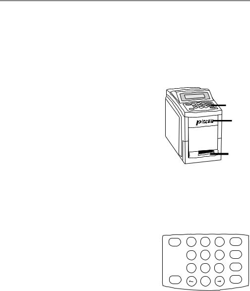
The Piccolo® Point-of-Care Chemistry Analyzer is a lightweight portable instrument that allows patient testing at the point of care. Its small footprint allows convenient placement of the analyzer in a nearpatient environment. The top surface has a 4-line display screen and keypad, and a recessed carrying handle. A sliding drawer and a slot for inserting result cards into the internal printer are on the front surface. The back surface includes connections for AC and DC power supply, as well as RS232 ports.
Display
Keypad
Drawer
Result
Card
Slot
1.5.1Display and keypad
The keypad and 4-line display screen facilitate interactive communication between the analyzer and the operator. The display indicates the status of the analyzer, and presents procedural instructions and error messages. It also reflects information input via the keyboard so it can be verified or corrected.
The operator inputs data through the 10 numeric keys, 6 function keys, and 2 arrow keys. Refer to the figure at the right for the keyboard layout. The specific uses of these keys are described in Sections 2, 3, and 4.
POWER |
7 |
8 |
9 |
RECALL |
|
4 |
5 |
6 |
MENU |
|
|
|||
|
1 |
2 |
3 |
EXIT |
|
|
The POWER key is used to power the analyzer up or |
CLOSE |
0 |
ENTER |
|
OPEN |
|
|
down and to cancel a run in progress. Refer to 2.2.3. The OPEN/CLOSE key operates the sliding drawer where the reagent disc sits. This key is referred to in
the text as either the OPEN or CLOSE key as appropriate in context. Closing a drawer containing a reagent disc initiates an analysis. Two of the function keys, MENU and RECALL, provide access to special functions described in detail in Sections 3 and 4.
1.5.2Disc drawer
The disc drawer slides in and out to transport the reagent disc into the analyzer and hold it in place during the analysis. Keep the analyzer drawer closed when not loading or unloading a reagent disc. Always use the OPEN/CLOSE key to change the position of the drawer. Do not push on the drawer to close it. This may damage the instrument.
1-2 |
Piccolo Features and Components |
Piccolo Operator’s Manual
1.5.3Result card slot
The result card slot, on the front surface of the analyzer below the disc drawer, provides access into the internal thermal printer. Refer to 1.6, 2.2.2, and Section 4 for information about printing result cards.
1.5.4Power supply
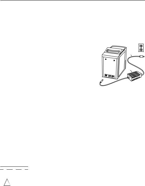
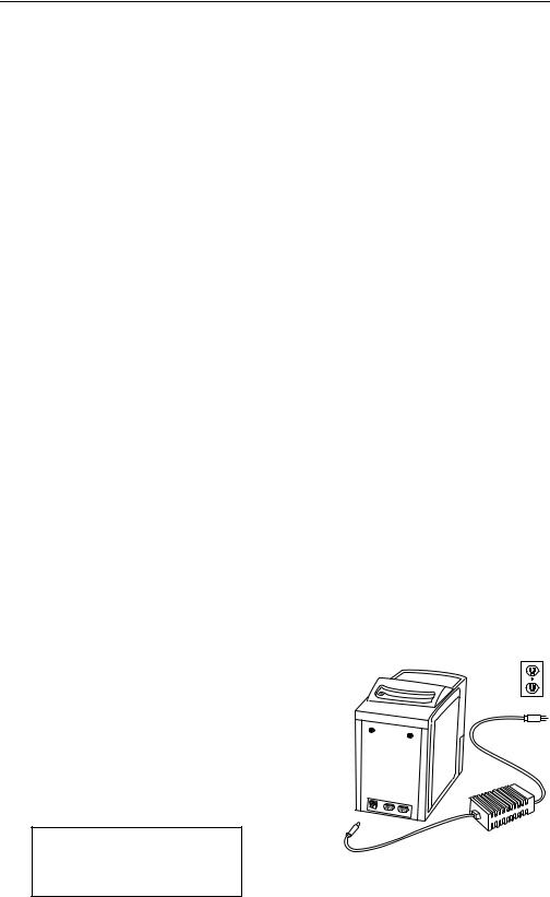
The analyzer runs on AC or DC power, providing portability in point-of-care testing environments.
Two power supply components are included. The DC power supply plugs into the socket on the lower left back of the analyzer. An AC power cord connects the DC power adaptor to a grounded electrical outlet. A “universal” DC-to-AC power convertor is also available, as well as an accessory that can plug into a vehicle’s lighter socket, allowing a 12-volt battery to be used as the power source.
Recessed
handle  AC Power
supply cord
Power
supply
RS232 computer  ports
ports 
 DC Power supply cord
1.5.5Computer ports
Two RS232 ports support 2-way communication between the analyzer and external devices. Port 1 [labeled RS232(1)] is used for connecting the analyzer to a computer to transmit results. Port 2 is used for connecting an optional bar code scanner. Refer to 1.11 for information on linking the analyzer to an external computer.
1.5.6Symbols used in labeling
The following symbols are found on the label on the bottom panel or above the connections on the back panel.
Symbol |
Explanation |
!
Direct current
Caution (refer to accompanying documents)
Serial ports
Piccolo Features and Components |
1-3 |

Piccolo Operator’s Manual
1.5.7Physical and environmental specifications
Height: |
24.2 cm |
9.5 inches |
Width: |
15.3 cm |
6 inches |
Depth: |
29.2 cm |
11.5 inches |
Weight of the analyzer: |
6.8 kg |
15 pounds |
Weight of the power adapter: |
0.6 kg |
1.3 pounds |
Mode of operation: |
|
Continuous |
Protection against ingress of fluids: |
Ordinary equipment (IPXO) |
|
Ambient operating temperature: |
|
15–32°C 59–90°F |
Humidity: |
|
0–95%, non-condensing |
Reaction temperature: |
|
37°C 98.6°F |
Power requirements: |
|
240–100 volts AC 50–60 Hz |
|
|
or 12–15 volts DC |
Thermal protection rating: |
|
70°C 178°F |
1.6Internal components
Inside the analyzer is a variable speed motor to spin the disc, a spectrophotometer to measure analyte concentrations, two microprocessors to control testing and analytical functions, system software on a PCMCA card, and a thermal line printer for imprinting result cards. A heating system maintains the temperature of the disc at 37°C while reactions are in progress.
1.6.1Optics
The measurement optics consist of a discrete wavelength spectrophotometer with a xenon lamp as a light source.
1.6.2Microprocessors and memory
The architecture of the instrument consists of two microprocessors: a real-time controller that monitors and controls all the measurements; and an I/O (input/output) controller for memory management, calculations, and data storage. The two processors cross-check each other’s performance continuously, which allows a very high level of confidence in the working of the instrument, and consequently of the results and the integrity of the data.
The analyzer stores 70 patient results, 70 control results, and system quality control data. All data stored in memory can be accessed via the Recall function. Refer to
Section 4.
1-4 |
Piccolo Features and Components |
Piccolo Operator’s Manual
1.6.3Software
The analyzer software comprises two matched programs. One program controls the measurement engine itself, i.e., it schedules the flashing of the light source and collects the light intensity data for different cuvettes at different times during the reaction; and it collects all the information generated in the analytical part of the instrument. The second program processes that information and reports analyte concentration. It also stores data related to each run (time, date, user ID, patient results, and control data).
Software upgrades are distributed to registered users on a PCMCA card and installed on site. Refer to 5.3 for instructions on installing a software card.
1.7Piccolo reagent discs
1.7.1Disc structure and function
In the Piccolo® system, all chemistry reactions are performed inside clear plastic reagent discs, 8 cm in diameter and 2 cm in depth, specially designed to perform all the steps required to convert a few drops of whole blood, plasma, or serum into a panel of test results. Each disc contains all the components and reagents needed to perform one or more tests on a single sample.
A total of 30 cuvettes are located around the periphery: 4 system cuvettes contain QC reagent beads for instrument and chemistry quality control (refer to 1.9); a minimum and a maximum absorbance cuvette are employed in calibrating the spectrophotometer; a specially designed cuvette detects whether sufficient sample volume was applied; one cuvette verifies that a sufficient aliquot of diluted sample was delivered to the reaction cuvettes; an empty cuvette captures excess fluids. The remaining 21 cuvettes contain test-spe- cific lyophilized reagent beads.
Bar Code Ring
Cuvettes
 Sample Port
Diluent
Container
Sample Fill Line
The bar code ring attached to the top of the reagent disc contains calibration data specific for the chemistries in the disc. It also contains the disc identification code, lot number, and expiration date. The analyzer automatically checks the code and rejects an expired disc. The bar code ring also protects the optical surfaces of the cuvette from fingerprints and other debris, and helps minimize contamination of the analyzer by capturing small drops of blood that may be on the disc surface.
The sample port, demarcated by an arrow pointing to a circle molded onto the upper surface of the disc, provides access to the sample chamber. When sufficient sample has been loaded into the sample chamber, the sample fill line forms between two arrows molded on the disc surface.
Piccolo Features and Components |
1-5 |

Piccolo Operator’s Manual
A sample diluent is sealed in a container inside the center of the disc. At the beginning of the reaction cycle, the analyzer opens the container and releases the diluent.
The analyzer separates a heparinized whole blood sample by centrifugation inside the disc. Plasma and serum samples are unaffected. Precisely measured quantities of sample and diluent are delivered to the mixing chamber. Then centrifugal and capillary forces deliver the diluted sample to the cuvettes, where it dissolves the reagent beads and initiates the chemical reactions. Reaction products in the cuvettes are measured photometrically.
1.7.2Disc storage and handling
•Store all reagent discs as described on their respective labels. When stored as described as described on their respective labels, all reagents in the disc are stable until the expiration date printed on the foil pouch and encoded on the bar code ring. The analyzer will reject an expired disc.
•A disc can be used directly from the refrigerator (stored at 2–8°C) without warming.
•A disc can remain in its sealed pouch at room temperature for a cumulative period of 48 hours. Longer time at room temperature can cause suppression of chemistries and disc aborts.
•Do not expose discs, in or out of the foil pouches, to direct sunlight or to temperatures above 32°C (90°F).
•Inspect the unopened foil pouch for tears and punctures. A torn or damaged pouch may allow moisture to reach the disc and reduce reagent performance.
•Open the disc pouch at the notch on the top right edge of the package. A disc must be used within 20 minutes of opening the pouch. Once the pouch is opened, do not place the disc back in the refrigerator for use at a later time.
•Discs are fragile. Handle with care. Do not tap the disc on the table or work bench to empty the sample port. Do not use a disc that has been dropped.
•Keep discs clean. Handle them only at the edges to avoid smudges on the optical surfaces. Use a lint-free tissue to remove blood from the disc surface.
•Write the patient identification number on the disc surface in the space indicated in the figure to the right (optional). Do not write anywhere else on the disc or on the bar code ring.
Write Patient ID
Here
•Hold reagent discs flat after introducing the sample or control to avoid spillage.
•The used disc can be replaced in the pouch for disposal.
•BIOHAZARD: Used reagent discs contain body fluids. Follow good laboratory working prac-
tices. Handle all used discs as if they are contaminated with hepatitis or other infectious diseases. Check with the appropriate state agency regarding disposal regulations.
1-6 |
Piccolo Features and Components |
Piccolo Operator’s Manual
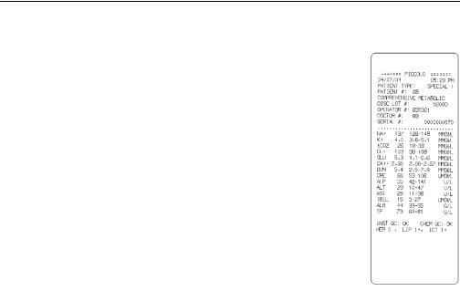
1.8Result cards
Result cards are durable paper strips, about 7.5 inches long by 2.5 inches wide, designed for use with the Piccolo® Point-of-Care Chemistry Analyzer, on which test results and other information can be printed after testing is complete. Result cards are also used for printing the QC report and the troubleshooting report to assist in the interpretation of error codes. Additional copies of the result card can be printed at any time for any analysis held in memory. Refer to 2.2.2 and Section 4 for information about printing result cards, QC report cards, and troubleshooting reports. Refer to 1.13 for ordering information.
The result card has an adhesive backing so it can be placed into the patient’s file. The operator should follow the institution’s procedures for disposition of the result card.
1.9Intelligent QC (iQC™)
The Piccolo® Point-of-Care Chemistry Analyzer includes design and user interface features that perform comprehensive system-wide quality control checks during each run. These features, collectively called “intelligent QC” (iQC™), ensure that operators at a wide range of skill levels can achieve accurate and reliable results. Two types of QC reagent beads (instrument and chemistry) are included in each disc. Refer to 1.7.1 for information about disc structure. When these methods confirm that all parameters are within expected ranges, INSTRU QC:OK CHEM QC:OK is printed on the result card. Otherwise, no result card is printed and an error message is displayed. Error messages indicate analyzer or disc malfunctions, and explain why results may not be available. Whenever an error message is displayed, refer to 5.6 for troubleshooting procedures.
System and chemistry QC data from each patient sample are stored in the analyzer memory with the sample results. System and chemistry QC data from each control run are stored with control results, separately from sample results. Standard information storage and retrieval techniques are employed to ensure the integrity of the data. All QC data stored in memory can be called up for review at any time. Refer to Section 4 for complete information and detailed instructions.
iQC™ greatly reduces the requirement for routine control testing. Refer to 2.4 for recommendations and procedure for control testing. Operators requiring assistance setting up control testing procedures should contact Abaxis Technical Support at 800-822-2947.
Piccolo Features and Components |
1-7 |

Piccolo Operator’s Manual
1.9.1Instrument iQC™
The analyzer hardware is subjected to a self-test at power-up. The self-test ensures that all optics, the flash lamp, and the circuit board components are functioning properly, and also verifies the memory functions. If any component does not meet specification, an error message is displayed. The disc motor, flash lamp, temperature, and optics are monitored continuously throughout each analysis. The spectrophotometer is automatically recalibrated at the beginning of each analysis.
Simultaneously with each analysis, advanced optical sensing and electronic systems monitor reactions involving instrument QC reagent beads to verify the functioning of the analyzer and the disc
1.9.2Reagent iQC™
Reactions involving chemistry QC reagent beads reveal and quantify any degradation of the test-specific reagents in the disc due to suboptimal storage conditions. The value reported is the actual absorbance as a percent of the expected absorbance. The value must exceed a defined minimum for the reagents to meet performance standards. Otherwise, the run is aborted and an error message is displayed.
A lot-specific cutoff value for chemistry QC absorbance is used to separate the various tests on the disc into two groups, based on different sensitivity to heat exposure. If the chemistry QC value falls below this cutoff level but above the defined minimum, the results from the less heat-sensitive tests are expected to meet performance standards. The results of these tests are printed. The results of the more heat-sensitive tests may show some degradation and are suppressed. (This cutoff level is not printed on the quality control report.)
1.9.3Performance iQC™
Disc checks performed during the analysis include: checking the barcode for current dating and for the presence of all required calibration factors; confirming that sample volume is sufficient; confirming the presence of all reagent beads and that all reagent beads have dissolved in diluted sample; verifying diluent and sample mixing; and monitoring fluid movement throughout the disc for proper sequence and timing of the reactions.
The iQC system monitors the performance of the reactions. For rate chemistries, the analyzer confirms that the reactions are linear; that the absorbances from which the rates are calculated, as well as the rates themselves, are within defined ranges; and whether the substrate has been depleted. In endpoint chemistries, the analyzer verifies that all measurements are within the dynamic range of the photometer and that the reaction has reached completion, ie, there are no changes in absorbance as a function of time.
The analyzer measure the levels of hemolysis, lipemia, and icterus. If there was interference with the analyte, information about the interference is printed on the result card. Refer to 2.3 for additional information.
1-8 |
Piccolo Features and Components |
Piccolo Operator’s Manual
1.10 Setup and power supply
1.10.1 Shipping verification
Remove the analyzer from the shipping carton and place it on a level surface. Check the components you received against the following list.
•Piccolo® Point-of-Care Chemistry Analyzer
•Piccolo® Operator's Manual
•DC power adapter and connector cord
•AC power cord
•warranty card
Note: Fill out the warranty card and mail it to Abaxis within 10 days of system installation to start the warranty period. You will be put on the Abaxis customer list to receive any information pertaining to your analyzer and ancillary products, including product updates.
1.10.2 Powering up
•Use only the power supply components provided with the analyzer. Using other power supply components will damage the instrument and void the warranty.
•Connect the analyzer only to a grounded electrical outlet.
•To prevent power surges or drain, do not plug the analyzer into the same circuit as a centrifuge or any other high-current device. Alternatively, use an ancillary surge protector or uninterruptable power supply (UPS).
•Place the analyzer on a level surface free of vibration and sudden jolts, and where the ambient temperature is 15−32°C (59−90°F). Do not place it near a sunny window or other heat source.
•There should be at least 6 inches clearance behind the analyzer for access to the power connection and RS232 ports.
•Place the analyzer where airborne matter such as dust, lint, and hair is limited; ie, do not place it near a fan or where air circulation is high.
Step 1. Connect the power supply.
Refer to the figure at the right. Plug the DC adapter into the socket on the back of the analyzer. Connect the AC power cord to the DC adapter. Plug the AC power cord into a grounded electrical outlet. The self-test message will appear on the display. The self-test is described in 1.9.1. If the display is blank, check all power supply connections.
Performing self-test
Piccolo Features and Components |
1-9 |

Piccolo Operator’s Manual
Step 2. Allow the analyzer to warm to operating temperature.
Depending on the ambient temperature, warming may take more time than the selftest.
The analyzer is in standby mode, i.e., ready to run a disc, when the display reads:
Open drawer to run a disc.
Step 3. Check the date and time.
Check the analyzer date and time to ensure they are correct. Refer to 3.3 to change the date and time.
Step 4. Link the analyzer to an external computer. (Optional)
Refer to 1.11.
Step 5. Perform control testing.
Perform one or more runs using recommended controls before running patient samples to confirm that the analyzer is functioning to specification. Refer to 2.4 for control run procedures.
1.10.3 Powering down
The power should remain on unless you are moving the analyzer to a new location. Always power down using the POWER key rather than by unplugging the analyzer. The POWER key does not power down the analyzer when there is a reagent disc in the drawer.
This message appears when the POWER key is pressed. Press EXIT to cancel the system shutdown procedure and return the analyzer to standby mode.
Turn analyzer OFF? Press POWER/OFF to turn off, or EXIT to continue operation.
Press POWER again to initiate system shutdown. The analyzer turns off when the system shutdown is complete.
Performing system shutdown.
1-10 |
Piccolo Features and Components |

Piccolo Operator’s Manual
1.11 Connecting to an external computer
A facility may want to connect the analyzer to an external computer for any or all of the following reasons: to incorporate testing data into patient records; to provide records for regulatory compliance; or to connect with automated billing systems. By default, the analyzer does not transmit data, but it can be configured to transmit data in simple ASCII text, or in ASTM E 1394-97. Contact Abaxis for detailed information on connecting the analyzer to a computer.
1.12 Bar Code Scanner Option/Requirements
For ease of entry of patient identification, the Piccolo Point-of-Care Blood Analyzer can be used with any Bar Code Scanner that meets the following requirements:
1.12.1 Communication Interface
The communication interface must be a serial connection using a female 9-pin D-SUB connector. The TX (transmit) should be on pin 2, and the RX (receive) should be on pin 3.
1.12.2 Communication Parameters
Data is received at 9600 Baud, No Parity, 8 Bits, and 1 Stop Bit (9600,N,8,1).
1.12.3 Barcode Formats
The scanner should auto discriminate at a minimum Code 39 and Code 128 symbologies. There can be no preamble in the output data. The postamble in the output data shall have CR (Carriage Return [0x0D]), LF (Line Feed [0x0A]) and NULL [0x00]).
1.13 Consumables and ancillaries
Contact Abaxis or your authorized distributor to order reagent discs, result cards, controls, and sample collection equipment and supplies.
1.14 Customer service and technical support
Call Abaxis Customer Service and Technical Support at 800-822-2947 with questions regarding the operation the Piccolo® Point-of-Care Chemistry Analyzer.
Piccolo Features and Components |
1-11 |


Piccolo Operator’s Manual
Section 2: Testing Procedure and
Interpretation of Results
2.1Sample requirements
•The Piccolo® Point-of-Care Chemistry Analyzer accepts heparinized whole blood, heparinized plasma, or serum samples.
•Lithium heparin is the only anticoagulant recommended for use with the Piccolo® Point-of-Care Chemistry Analyzer.
•For use of the CLIA ‘88 Waived Lipid Panel Disc, the only sample that may be used is lithium heparinized whole blood.
•A sample size of 90–120 µL is required.
•Whole blood must be analyzed within 60 minutes of collection, or separated into plasma or serum.
•To prevent hemolysis, do not refrigerate or shake whole blood.
•If not analyzed immediately, plasma or serum (separated) may be stored at room temperature for no longer than 5 hours after centrifugation. If storage for more
than 5 hours is required, the sample should be refrigerated in the stoppered tube at 2–8°C (36–46°F) for no longer than 48 hours; or stored at −10°C for up to 5 weeks in a freezer without a self-defrost cycle. Under these conditions, there will be no clinically important changes in most analyte concentrations.
•For accurate interpretation of results, the sample should be collected from a patient who has fasted for at least 12 hours (to avoid lipemic samples).
•Operator health and safety require that Universal Precautions be observed at all times while handling human blood samples or working with the Piccolo® Point- of-Care Chemistry Analyzer in any way. The complete text of the document “OSHA 29 CFR Part 1910, Occupational Exposure to Bloodborne Pathogens” can be found on the Internet at www.osha-slc.gov/Preamble/Blood_toc_by_sect.html.
2.2Testing procedure
•Wear powder-free gloves while handling reagent discs or operating the analyzer. Powder may disrupt the optical components.
•If necessary, power up the analyzer before beginning the procedure. The power-up procedure is described in 1.10.2.
•Ensure that the ambient temperature is 15–32°C (59–90°F).
•The analyzer is in standby mode, i.e., ready to run a disc, when the display reads:
Open drawer to run a disc.
Testing Procedure and Interpretation of Results |
2-1 |

Piccolo Operator’s Manual
2.2.1Preparing the reagent disc
•Refer to 1.7 for complete information about Piccolo® reagent discs, including handling instructions. Please become thoroughly familiar with this information before beginning the procedure.
•Refer to 2.1 for sample handling and storage requirements.
•The analysis must begin immediately (no more than 10 minutes) after dispensing the sample into the reagent disc.
Step 1. Dispense the sample.
Use a micropipette (one is included with the Piccolo) or other transfer device to dispense approximately 100 µL of sample into the disc via the sample port.
Write Patient ID
Here
a.Fill the sample port.
Expel air bubbles from the tip of the micropipette. Place the micropipette in the sample port and tilt it until it is perpendicular to the disc surface. Push down on the plunger with a slow, continuous motion.
Take care not to overfill the sample chamber. A 100 µL sample will fill the sample chamber and form a line between the two arrows molded on the disc. More than 120 µL of sample will overfill the chamber, and less than 90 µL will underfill. Discard the pipette tip into a biohazard container.
90 L
> 90 L < 120 L
<90 L
> 120 L
b.Fill the sample chamber.
Tilt the disc to 45° with the sample port above the fill line, so that the entire sample flows into the sample chamber. Clean the reagent disc. Use a lint-free tissue to remove any sample spilled on the outside of the disc, taking care that the tissue does not withdraw any sample from the sample port. Dispose of the tissue in a biohazard container.
c.Carry the prepared disc to the analyzer.
Hold the disc by its edges in a flat position.
2-2 |
Testing Procedure and Interpretation of Results |
Piccolo Operator’s Manual
2.2.2Running a patient sample
•The analyzer must be in standby mode to begin the procedure.
•Use the numeric and arrow keys to enter patient, operator, and physician IDs while the analysis is proceeding. The → key inserts a dash; the ← key deletes the character to the left.
•The reference range set and patient, operator, and physician IDs must be entered before results can be calculated. If you wait until the run is complete before entering these numbers, the analyzer will require an additional one minute to calculate the results.
•If an error message is displayed at any time during the run, refer to 5.6 for troubleshooting procedures associated with the specific error code.
Step 2. Open the drawer and insert the disc.
Press OPEN. The following messages are displayed sequentially:
Opening drawer...
Close drawer to start analysis.
Place the disc in the drawer. Press CLOSE. The display reads:
Closing drawer...
The analysis begins when the drawer closes.
Step 3. Select the reference range set.
By default, the reference range set for the previous sample is displayed. The reference range set for the current sample must be selected for correct interpretation of results. Use the numeric keys to select the correct reference range set. Press ENTER when the correct number appears to the right of Select.
Select:1 |
MALE |
|
1- |
Male |
3- Special |
2- |
Female |
4- Control |
ENTER to |
accept. |
|
|
|
|
Testing Procedure and Interpretation of Results |
2-3 |

Piccolo Operator’s Manual
Step 4. Enter the patient ID.
A patient ID (up to 14 characters) must be entered to continue. Press ENTER.
Input Patient #:
_ _ _ _ _ _ _ _ _ _ _ _ _ _
ENTER when finished.
Step 5. Enter the operator ID.
Enter the operator ID for the current sample, up to 14 characters. Press ENTER.
Input Operator #:
_ _ _ _ _ _ _ _ _ _ _ _ _ _
ENTER when finished.
Step 6. Enter the physician ID.
Enter the physician ID for the current sample, up to 14 characters. Press ENTER.
Input DR #:
_ _ _ _ _ _ _ _ _ _ _ _ _ _
ENTER when finished.
Step 7. Automatic sample processing.
The analyzer processes the sample and calculates results in less than 13 minutes with no further operator input. During the run, the analyzer displays the following message, including time remaining to complete the analysis (XX:XX) and patient ID.
Results ready in XX:XX
for patient #: XXXXXXXXXXXXXX
Sample processing is complete when the analyzer beeps and displays these messages sequentially:
Analysis complete. Open drawer or insert card to print results.
Insert card to print results.
2-4 |
Testing Procedure and Interpretation of Results |

Piccolo Operator’s Manual
Step 8. Print results.
To end the procedure without printing results, press EXIT and continue to step 9.
If a Run Cancelled error message is displayed, refer to 5.6 for an explanation and further instructions.
Place the result card in the result card slot. Remove the card when directed to do so on the display. These messages appear sequentially:
Printing results...
Remove card.
Opening drawer...
Remove disc
and close drawer.
If the results card shows one or more rows of diamonds (♦♦♦) in place of analyte concentration, this indicates suppressed results. Refer to 2.3.2 B. In this situation, insert a second results card when prompted.
Step 9. Return the analyzer to standby mode.
Remove the reagent disc from the drawer and dispose of it, following your lab’s biohazard procedures. Press CLOSE to return the analyzer to standby mode.
2.2.3Canceling an analysis in progress
Press POWER to cancel an analysis in progress. The display requests verification that the analysis should be canceled:
Cancel analysis? POWER/OFF to cancel run, or EXIT to continue analysis.
Testing Procedure and Interpretation of Results |
2-5 |
Loading...