

Page 1
Operator’s Manual
Page 2

Piccolo® Point-of-Care Che mi stry An al yze r
Operator’s Manual
For in vitro diagnostic use
Abaxis, Inc. 3240 Whipp le Road Union City, California, USA 94587
800-827-2947 Customer Service and Technical Support
PN 100-7008 Rev. G
March 13, 2001
Page 3

Piccolo Operator’s Manual
Table of Contents
Section 1: Piccolo Features and Components
1.1 Intended use . . . . . . . . . . . . . . . . . . . . . . . . . . . . . . . . . . . . . . . . .1-1
1.2 Universal precautions . . . . . . . . . . . . . . . . . . . . . . . . . . . . . . . . .1-1
1.3 Near-patient testing efficiency . . . . . . . . . . . . . . . . . . . . . . . . .1-1
1.4 Overview of the procedure . . . . . . . . . . . . . . . . . . . . . . . . . . . .1-1
1.5 External features . . . . . . . . . . . . . . . . . . . . . . . . . . . . . . . . . . . . .1-2
1.5.1 Display and keypad . . . . . . . . . . . . . . . . . . . . . . . . . . . . 1-2
1.5.2 Disc drawer . . . . . . . . . . . . . . . . . . . . . . . . . . . . . . . . . . . 1-2
1.5.3 Result card slot . . . . . . . . . . . . . . . . . . . . . . . . . . . . . . . .1-3
1.5.4 Power supply . . . . . . . . . . . . . . . . . . . . . . . . . . . . . . . . . 1 -3
1.5.5 Computer ports . . . . . . . . . . . . . . . . . . . . . . . . . . . . . . .1-3
1.5.6 Symbols Used in Labeling . . . . . . . . . . . . . . . . . . . . . .1-3
1.5.7 Physical and environmental specifications. . . . . . . . .1-4
1.6 Internal components . . . . . . . . . . . . . . . . . . . . . . . . . . . . . . . . . .1-4
1.6.1 Optics . . . . . . . . . . . . . . . . . . . . . . . . . . . . . . . . . . . . . . . . 1-4
1.6.2 Microprocessors and memory . . . . . . . . . . . . . . . . . . .1-4
1.6.3 Software . . . . . . . . . . . . . . . . . . . . . . . . . . . . . . . . . . . . . .1-5
1.7 Piccolo reagent discs . . . . . . . . . . . . . . . . . . . . . . . . . . . . . . . . . .1-5
1.7.1 Disc structure and function . . . . . . . . . . . . . . . . . . . . . 1-5
1.7.2 Disc storage and handling . . . . . . . . . . . . . . . . . . . . . .1-6
1.8 Result cards . . . . . . . . . . . . . . . . . . . . . . . . . . . . . . . . . . . . . . . . .1-7
1.9 Intelligent QC (iQC™) . . . . . . . . . . . . . . . . . . . . . . . . . . . . . . . .1-7
1.9.1 Instrument iQC™ . . . . . . . . . . . . . . . . . . . . . . . . . . . . . . 1-8
1.9.2 Reagent iQC™ . . . . . . . . . . . . . . . . . . . . . . . . . . . . . . . .1-8
1.9.3 Performance iQC™ . . . . . . . . . . . . . . . . . . . . . . . . . . . .1-8
1.10 Setup and power supply . . . . . . . . . . . . . . . . . . . . . . . . . . . . . .1-9
1.10.1 Shipping verification . . . . . . . . . . . . . . . . . . . . . . . . . . . 1-9
1.10.2 Powering up . . . . . . . . . . . . . . . . . . . . . . . . . . . . . . . . . . 1-9
1.10.3 Powering down . . . . . . . . . . . . . . . . . . . . . . . . . . . . . .1-10
1.11 Connecting to an external computer . . . . . . . . . . . . . . . . . . . .1-11
1.12 Consumables and ancillaries . . . . . . . . . . . . . . . . . . . . . . . . . . .1-11
1.13 Customer service and technical support . . . . . . . . . . . . . . . . .1-11
Page 4

Section 2: Testing Procedure and
Interpretation of Results
2.1 Sample requirements . . . . . . . . . . . . . . . . . . . . . . . . . . . . . . . . .2-1
2.2 Testing procedure . . . . . . . . . . . . . . . . . . . . . . . . . . . . . . . . . . . .2-1
2.2.1 Preparing the reagent disc . . . . . . . . . . . . . . . . . . . . . .2-2
2.2.2 Running a patient sample . . . . . . . . . . . . . . . . . . . . . . .2-3
2.2.3 Canceling an analysis in progress . . . . . . . . . . . . . . . .2-5
2.3 Interpreting patient results . . . . . . . . . . . . . . . . . . . . . . . . . . . .2-6
2.3.1 Reading the result card . . . . . . . . . . . . . . . . . . . . . . . . .2-6
2.3.2 Abnormal results: interpretation and further action 2-7
2.4 Running controls . . . . . . . . . . . . . . . . . . . . . . . . . . . . . . . . . . . . .2-8
2.5 Limitations of the procedure . . . . . . . . . . . . . . . . . . . . . . . . . . .2-10
Section 3: The Menu Function
3.1 Run controls . . . . . . . . . . . . . . . . . . . . . . . . . . . . . . . . . . . . . . . . .3-1
3.2 Change the date and time . . . . . . . . . . . . . . . . . . . . . . . . . . . . .3-2
3.3 Select date format . . . . . . . . . . . . . . . . . . . . . . . . . . . . . . . . . . . .3-4
3.4 Select time format . . . . . . . . . . . . . . . . . . . . . . . . . . . . . . . . . . . .3-4
3.5 Select Units . . . . . . . . . . . . . . . . . . . . . . . . . . . . . . . . . . . . . . . . . .3-5
3.6 Customize reference ranges . . . . . . . . . . . . . . . . . . . . . . . . . . . .3-6
3.7 Print reference ranges . . . . . . . . . . . . . . . . . . . . . . . . . . . . . . . . .3-8
3.8 Transmit reference ranges . . . . . . . . . . . . . . . . . . . . . . . . . . . . .3-9
3.9 View analyzer identification . . . . . . . . . . . . . . . . . . . . . . . . . . .3-10
Section 4: The Recall Function
4.1 Scanning patient results in chronological order . . . . . . . . . . .4-1
4.2 Recalling results by specifying patient ID . . . . . . . . . . . . . . . .4-3
4.3 Scanning control results in chronological order . . . . . . . . . . .4-5
4.4 Recalling a specific control result . . . . . . . . . . . . . . . . . . . . . . .4-6
4.5 Scanning system QC data associated with patient results
in chronological order . . . . . . . . . . . . . . . . . . . . . . . . . . . . . . . . .4-8
Page 5

4.6 Recalling System QC data associated with patient results
by specifying patient ID . . . . . . . . . . . . . . . . . . . . . . . . . . . . . . .4-10
4.7 Scanning system QC data associated with control results in chronological order 4-12
4.8 Recalling system QC data associated with
a specific control result . . . . . . . . . . . . . . . . . . . . . . . . . . . . . . . .4-13
4.9 Transmitting results to an external computer . . . . . . . . . . . . .4-16
4.10 Transmitting system QC to an external computer . . . . . . . . .4-17
4.11 No results in memory . . . . . . . . . . . . . . . . . . . . . . . . . . . . . . . . .4-18
4.12 No system QC in memory . . . . . . . . . . . . . . . . . . . . . . . . . . . . .4-18
Section 5: Maintenance and Troubleshooting
5.1 Routine maintenance . . . . . . . . . . . . . . . . . . . . . . . . . . . . . . . . .5-1
5.1.1 Cleaning the exterior . . . . . . . . . . . . . . . . . . . . . . . . . . .5-1
5.1.2 Cleaning the printer . . . . . . . . . . . . . . . . . . . . . . . . . . . . 5-1
5.1.3 Cleaning the air filter . . . . . . . . . . . . . . . . . . . . . . . . . . .5-2
5.2 Clearing a paper jam . . . . . . . . . . . . . . . . . . . . . . . . . . . . . . . . . .5-3
5.3 Installing a software card . . . . . . . . . . . . . . . . . . . . . . . . . . . . . .5-4
5.4 Reinitializing the analyzer . . . . . . . . . . . . . . . . . . . . . . . . . . . . .5-5
5.5 Returning the analyzer to Abaxis for service . . . . . . . . . . . . .5-5
5.6 Error messages . . . . . . . . . . . . . . . . . . . . . . . . . . . . . . . . . . . . . . .5-6
Page 6

Page 7
Piccolo Operator’s Manual
Section 1: Piccolo Features and Components
1.1 Intended use
The Piccolo® Point-of-Care Chemistry Analyzer provides quantitative in vitro determinations of clinical chemistry analytes in heparinized whole blood, heparinized
plasma, or serum.
1.2 Universal precautions
Operator health and safety require that universal precautions be observed at all times
while handling human blood samples or working with the Piccolo® Point-of-Care
Chemistry Analyzer in any way. The complete text of the document “OSHA 29 CFR
Part 1910, Occupational Exposure to Bloodborne Pathogens” can be found on the
Internet at www.osha-slc.gov/Preamble/Blood_toc_by_sect.html.
1.3 Near-patient testing efficiency
This near-patient portable clinical chemistry system provides the clinician with routine multi-chemistry profiles and electrolytes for panels of blood tests within minutes.
Less than 2 minutes of hands-on time is required to perform the test. The Piccolo®
Point-of-Care Chemistry Analyzer eliminates the need to transport samples to a central laboratory, and reduces such problems as misplaced samples, inaccurate labeling
and transcription, improper icing and bagging, and sample degradation. Test systems
must produce reliable results when used by operators with a wide range of skill levels. An important criterion is ease of use, and automated systems with minimal handling and processing steps, like the Piccolo® Point-of-Care Chemistry Analyzer, are
easy to operate and are widely used in near-patient environments.
1.4 Overview of the procedure
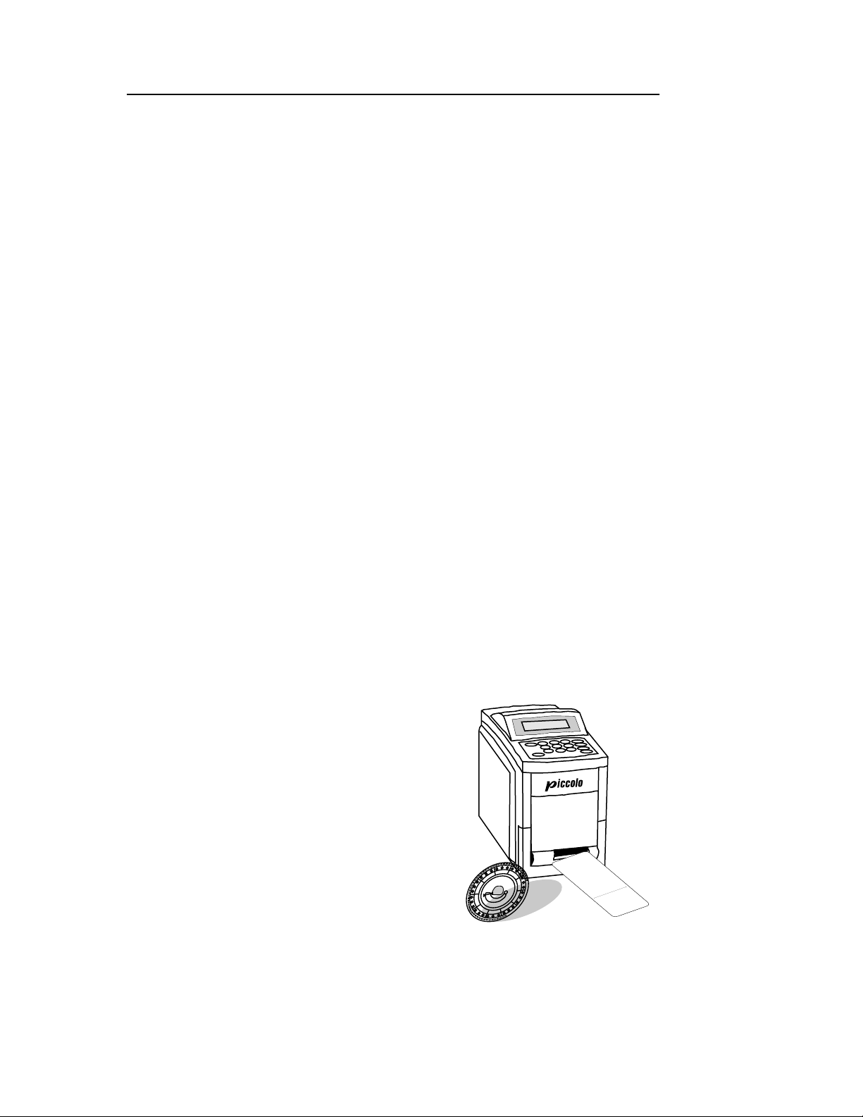
The Piccolo® system consists of the Piccolo® Pointof-Care Chemistry Analyzer, single-use disposable
reagent discs, and result cards printed by the analyzer . External and internal features of the analyzer
are described and illustrated below.
The operator begins the Piccolo procedure by introducing whole blood, plasma, or serum sample into
a self-contained reagent disc and loading the d isc
into the analyzer. No premeasuring or sample preparation steps are required. The operator then enters
patient, operator, and physician
numbers using
ID
the keypad and display screen. The analyzer performs the remainder of the testing protocol auto-
HEM
QC
3
+
,
OK
GLOB
LIP
3
TP
+
3
,
ICT
.0
K+
6
1
GLU
.3
+
2
4
.3
CRE
.5
-5
1
5
1
.2
.4
CHOL
2
-8
*
3
I
.2
.7
CT
CA++ LIP
-5
6
2
.8
G/DL
0
BUN
4
-1
4
1
0
G/DL
0
TBIL HEM
.3
>
MM0l/L
1
-
1
1
2
8
AMY
.3
5
0
-
8
MG/DL
2
.6
7
AL
-1
0
MG/DL
♦
7
1
T
-2
♦
.8
ALP
5
♦
<
0
MG/DL
1
.1
0
ALB
-0
MG/DL
2
LIP
.6
0
0
-1
3
MG/DL
1
.3
0
SERIAL#
2
-1
0
MG/DL
0
1
2
8
OPER
0
-
1
2
.5
5
U/L
DISC
:
0
-4
0
GENERAL
0
.4
0
U/L
0
0
#:
0
0
LOT #:
P
U/L
0
A
0
TIENT
G/DL
8
PATIENT
2
7
CHEMISTRY
0
4
/0
DR #:
5
/9
TYPE:
6
6
0
#:
5
0
4
0
0
1
0
12
A
3
1
9
5
-2
P
-
MALE
IC
1
1
:3
C
5
O
AM
L
O
Piccolo Features and Components 1-1
Page 8
Piccolo Operator’s Manual
matically in about 12 minutes. The used reagent disc is removed and the analyzer is
ready for the next sample.
The chemical reaction s carried o ut by this an alyzer a re designed t o pr oduce a reaction
that absorbs light at known wavelengths. Analyte concentration is calculated from
light absorbance data. Results can be printed on result cards for purposes of assessment and for inclusion in the patient’s medical chart. Results are stored in the analyzer memory, and can be transmitted to an external computer.
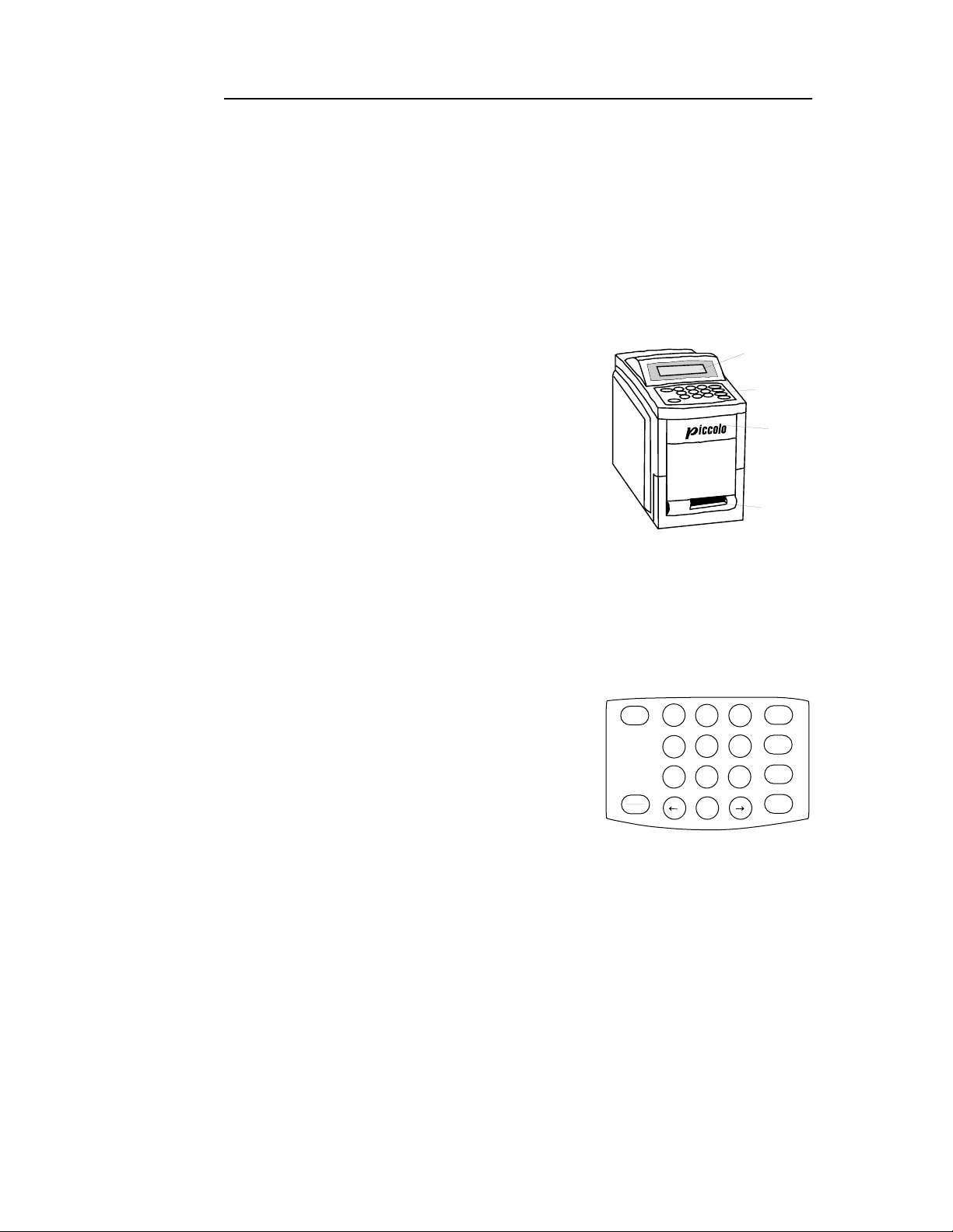
1.5 External features
The Piccolo® Point-of-Care Chemistry Analyzer is a
lightweight portable instrument that allows patient
testing at the point of care. Its small footprint allows
convenient placement of the analyzer in a near-
Display
Keypad
Drawer
patient environment. The top surface has a 4-line display screen and keypad, and a recessed carrying handle. A sliding drawer and a slot for inserting result
cards into the internal printer are on the front surface.
The back surface has DC power supply and RS232
ports.
Result
Card
Slot
1.5.1 Display and keypad
The keypad and 4-line display screen facilitate interactive communication between
the analyzer and the operator. The display indicates the status of the analyzer, and
presents procedural instructions and error m essages. It also reflects info rmation input
via the keyboard so it can be verified or corrected.
The operator inputs data through the 10 numeric
POWER
OPEN
CLOSE
789
5
4
23
1
0
keys, 6 function keys, and 2 arrow keys. Refer to th efigure at the right for the keyboard layout. The specific uses of these keys are described in
Sections 2, 3
and 4.
The
down and to cancel a run in progress. Refer to
The
POWER
OPEN/CLOSE
key is used to power the analyzer up or
2.2.3
key operates the sliding drawer
,
.
where the reagent disc sits. This key is referred to in
the text as either the
OPEN
or
key as appropr i ate in context. Closing a drawer
CLOSE
containing a reagent disc initiates an analysis. Two of the function keys,
RECALL
, provide access to special functions described in detail in
Sections 3
MENU
RECALL
6
and
and 4.
MENU
EXIT
ENTER
1.5.2 Disc drawer
The disc drawer slides in and out to transport the reagent disc into the analyzer and
hold it in place during the analysis. Keep the analyzer drawer closed when not loading or unloading a reagent disc. Always use the
OPEN/CLOSE
1-2 Piccolo Features and Components
key to change the posi-
Page 9
Piccolo Operator’s Manual
tion of the drawer.
instrument.
Do not push on the drawer to close it. This may damage the
1.5.3 Result card slot
The result card slot, on the front surface of the analyzer below the disc drawer, provides access into the internal thermal printer. Refer to
1.6, 2.2.2
, and
Section 4
for
information about printing result cards.
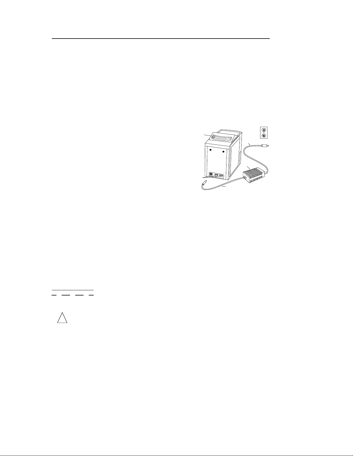
1.5.4 Power supply
The analyzer runs on DC power, providing portability in point-of-care testing environments.
Recessed
handle
AC Power
supply cord
Two power supply components are included. A
DC adapter
plugs into the socket on the lower left
back of the analyzer, allowing the use of a 12-volt
battery as the power source. An
AC power cord
connects the power adaptor to a grounded electrical outlet.
RS232
computer
ports
Power
adaptor
DC Power supply cord
1.5.5 Computer ports
Two RS232 ports support 2-way communication between the analyzer and external
devices. Only port 1 [labeled RS232(1)] should be used at this time. Port 2 is reserved
for future use. Refer to
computer.
1.11
for information on linking the analyz er to a n externa l
1.5.6 Symbols used in labeling
The following symb ols are found on the label on the bottom panel or above the connections on the back panel.
Symbol Explanation
Direct current
!
=
Caution (refer to accompanying documents)
Serial ports
Piccolo Features and Components 1-3
Page 10

Piccolo Operator’s Manual
1.5.7 Physical and environmental specifications
Height: 24.2 cm 9.5 inches
Wi dth: 15.3 cm 6 inches
Depth: 29.2 cm 11.5 inches
Weight of the analyzer: 6.8 kg 15 pounds
Weight of the power adapter: 0.6 kg 1.3 pounds
Mode of operation: Continuous
Protection against ingress of fluids: Ordinary equipment (IPXO)
Ambient operating temperature: 15–32°C 59–90°F
Humidity: 0–95%, non-co ndensing
Reaction temperature: 37°C 98.6°F
Power requirements: 250–90 volts AC 50–60 Hz
or 12–15 volts DC
Thermal protection rating: 70°C 178°F
1.6 Internal components
Inside the analyzer is a variable speed motor to spin the disc, a spectrophotometer to
measure anal yte co ncentrat ions, two mi cr opr oce ssor s to contr o l test ing an d analyt ical
functions, system software on a PCMCA card, and a thermal line printer for imprinting result cards. A heating system maintains the temperature of the disc at 37°C while
reactions are in progress.
1.6.1 Optics
The measurement optics consist of a discrete wavelength spectrophotometer with a
xenon lamp as a light source.
1.6.2 Microprocessors and memory
The architecture of the instrument consists of two microprocessors: a real-time controller that monitors and controls all the measurements; and an I/O (input/output)
controller for memory management, calculations, and data storage. The two processors cross-check each other’s performance continuously, which allows a very high
level of confidence in the working of the instrumen t, and consequently of the results
and the integrity of the data.
The analyzer stores 150 patient results, 75 control results, and system quality control
data. All data stored in memory can be accessed via the Recall function. Refer to
Section 4
.
1-4 Piccolo Features and Components
Page 11

Piccolo Operator’s Manual
1.6.3 Software
The analyzer software comprises two matched programs. One program controls the
measurement engine itself, ie, it schedules the flashing of the light source and collects
the light intensity data for different cuvettes at different times during the rea ction; and
it collects all the information generated in the analytical part of the instrument. The
second program processes that information and reports analyte concentration. It also
stores data related to each run (time, date, user
Software upgrades are distributed to registered users on a PCMCA card and installed
on site. Refer to
5.3
for instructions on installing a softwa re card.
, patient results, and control data).
ID
1.7 Piccolo reagent discs
1.7.1 Disc structure and function
In the Piccolo system, all chemistry reactions are performed inside clear plastic
reagent discs, 8 cm in diameter and 2 cm in depth, specially designed to perform all
the steps required to convert a few drops of whole blood, plasma, or serum into a
panel of test results. Each disc contains all the components and reagents needed to
perform one or more tests on a single sample.
A total of 30
the periphery: 4 system cuvettes contain
QC reagent beads for instrument and
chemistry quality control (refer to 1.9); a
minimum and a maximum absorbance
cuvette are employed in calibrating the
spectrophotometer; a specially designed
cuvette detects whether sufficient sample
volume was applied; one cuvette verifies
that a sufficient aliquot of diluted sample
was delivered to the reaction cuvettes; an
empty cuvette captures excess fluids. The
remaining 21 cuvettes contain test-specific lyophilized reagent beads.
bar code ring
The
cific for the chemistries in the disc. It also contains the disc identification code, lot
number, and expiration date. The analyzer automat ica lly checks the code and rejects
an expired disc. The bar code ring also protects the optical surfaces of the cuvette fr om
fingerprints and ot her debris, and helps minimize conta mination of the analyzer by
capturing small drops of blood that may be on the disc surface.
sample port,
The
surface of the disc, provides access to the
has been loaded into the sample chamber, the
arrows molded on the disc surface.
cuvettes
are located around
Bar Code Ring
Cuvettes
Sample Port
Diluent
Container
Sample Fill Line
attached to the top of the reagent disc contains calibration data spe-
demarcated by an arrow pointing to a circle molded onto the upper
sample chamber
sample fill line
. When sufficient sample
forms between two
Piccolo Features and Components 1-5
Page 12

Piccolo Operator’s Manual
A sample
diluent
is sealed in a container inside the center of the disc. At the begin-
ning of the reaction cycle, the analyzer opens the container and releases the diluent.
The analyzer separates a heparinized whole blood sample by centrifugation inside the
disc. Plasma and serum samples are unaffected. Precisely measur ed q uantities of sam ple and diluent are delivered to the
mixing chamber
. Then centrifugal and capillary
forces deliver the diluted sample to the cuvettes, where it dissolves the reagent beads
and initiates the chemical reactions. Reaction products in the cuvettes are measured
photometrically.
1.7.2 Disc storage and handling
• Store all reagent discs as described on their respective labels. When stored as
described as described on their respective labels, all reagents in the disc are stable
until the expiration date printed on the foil pouch and encoded on the bar code
ring. The analyzer will reject an expired disc.
• A disc can be used directly from the refrigerator without warming.
• A disc can remain in its sealed pouch at room temperature for a cumulative period
of 48 hours. Longer time at room temperature can cause suppression of chemistries
and disc aborts.
• Do no t expose discs, in or out of the foil pouches, to direct sunlight or to tempera-
tures above 32°C (90°F).
• Inspect the unopened foil pouch for tears and punctures. A torn or damaged
pouch may allow moisture to reach the disc and adversely affect reagent performance.
• Open the disc pouch at the notch on the top right edge of the package. A disc must
be used within 20 minutes of opening the pouch. Once the pouch is opened, do not
place the disc back in the refrigerator for use at a later time.
• Discs are fragile. Handle with care. Do not tap the disc on the table or work bench
to empty the sample port. Do not use a disc that has been dropped.
• Keep discs clean. Handle them only at the edges to avoid smudges on the optical
surfaces. Use a lint-free tissue to remove blood from the disc surface.
• Write the patient identification number on the
disc surface in the space indicated in the figure
Write Patient ID
Here
to the right (optional). Do not write anywhere
else on the disc or on the bar code ring.
• Hold reagent discs flat after introducing the
sample or control to avoid spillage.
• The used disc can be replaced in the pouch for
disposal.
• BIOHAZARD: Used reagent discs contain body
fluids. Follow good laboratory working practices. Handle all used discs as if they
are contaminated with hepatitis or other infectious diseases.
1-6 Piccolo Features and Components
Page 13

Piccolo Operator’s Manual
04/05/96
1:35
AM
PATIENT
TYPE: MALE
PATIENT
#:
103195-2-1
GENERAL CHEMISTRY
12
DISC LOT #:
6054 A
OPER #:
000 DR #: 000
SERIAL #: 000000827
ALB 3.3 2.5-4.4 G/DL
ALP L I P
20-150 U/L
ALT
<10
10-118
U/L
AMY
♦♦♦ 200-1200 U/L
TBIL HEM
0.1-0.6
MG/DL
BUN
>180
7-25
MG/DL
CA++ LIP
8.6-11.8
MG/DL
CHOL
24 4 125-270
MG/DL
CRE I C T
0.3-1.3
MG/DL
GLU
112* 60-110
MG/DL
K+
4. 5 3.7-5.8
MM0l/L
TP
6. 3 5.4-8.2 G/DL
GLOB
3. 0 2.3-5.2 G/DL
QC OK
HEM
3+ , LIP 3+ , ICT 1+
PICCOLO
1.8 Result cards
Result cards are durable paper strips, about 6 inches long by 2.5
inches wide, designed for use with the Piccolo
®
Point-of-Care
Chemistry Analyzer, on which test results and other information
can be printed after testing is complete. Result cards are also used
for printing the QC report and the troubleshooting report to assist
in the interpretation of error codes. Additional copies of the result
card can be printed at any time for any analysis held in memory.
Refer to
2.2.2
cards, QC report cards, and troubleshooting reports. Refer to
and
Section 4
for information about printing result
1.12
for ordering information.
The result card has an adhesive backing so it can be placed into the
patient’s file. The operator should follo w the institution’s procedures for disposition of the result card.
1.9 Intelligent QC (iQC™)
The Piccolo® Point-of-Care Chemistry Analyzer includes design an d user interf ace
features that perform compr ehensive sy stem-wide quality control checks during each
run. These features, collectively called “intelligent QC” (iQC™), ensure that operators
at a wide range of skill levels can achieve accu rate and reliable results. Two types of
QC reagent beads (instrument and chemistry) are included in each disc. Refer to
for information about disc structure. When these methods confirm that all parameters
are within expected ranges,
INSTRU QC:OK CHEM QC:OK
is printed on the result
card. Otherwise, no result card is printed and an error message is displayed. Error
messages indicate analyzer or disc malfunctions, and explain why results may not be
available. Whenever an error message is displayed, refer to
5.6
for troubleshooting
procedures.
1.7.1
System and chemistry QC data from each patient sample are stored in the analyzer
memory with the sample results. System and chemistry QC data from each control
run are stored with control results, separately from sample results. Standard information storage and retrieval techniques are employed to ensure the integrity of the data.
All QC data stored in memory can be called up for review at any time. Refer to
Section 4
for complete information and detailed inst ructions.
iQC™ greatly reduces the requirement for routine control testing. Refer to
ommendations and procedure for control testing. Operators requiring assistance setting up control testing procedures should contact Abaxis Technical Support.
Piccolo Features and Components 1-7
2.4
for rec-
Page 14

Piccolo Operator’s Manual
1.9.1 Instrument iQC™
The analyzer hardware is subjected to a self-test at power-up. The self-test ensures
that all optics, the flash lamp, and the circuit board components are functioning properly, and also verifies the memory functions. If any component does not meet specification, an error message is displayed. The disc motor, flash lamp, temperature, and
optics are monitored continuously throughout each analysis. The spectrophotometer
is automatically recalibrated at the beginning of each a na lysis.
Simultaneously with each analysis, advanced optical sensing and electronic systems
monitor reactions involving instrument QC reagent beads to verify the functioning of
the analyzer and the disc
1.9.2 Reagent iQC™
Reactions involving chemistry QC reagent beads reveal and quantify any degradation
of the test-specific reagents in the disc due to suboptimal storage conditions. The
value reported is the actual absorbance as a percent of the expected absorbance. The
value must exceed a defined minimum for the reagents to meet performance standards. Otherwise, the run is aborted and an error message is displayed.
A lot-specific cutoff value for chemistry QC absorbance is used to separate the various
tests on the disc into two groups, based on differen t sensitivity to heat exposure. If the
chemistry QC value falls below this cutoff level but above the defined minimum, the
results from the less heat-sensitive tests are expected to meet performance standards.
The results of these tests are printed. The results of the more heat-sensitive tests may
show some degradation and are suppressed. (This cutoff level is not printed on th e
quality control report.)
1.9.3 Performance iQC™
Disc checks performed during the analysis include: checking the barcode for current
dating and for the presence of all required calibration factors; confirming tha t sample
volume is sufficient; confirming the presence of all reagent beads and that all reagent
beads have dissolved in diluted sample; verifying diluent and sample mixing; and
monitoring fluid movement throughout the disc for proper sequence and timing of
the reactions.
The iQC system monitors the performance of the reactions. For rate chemistries, the
analyzer confirms that the reactions are linear; that the absorbances from which the
rates are calculated, as well as the rates themselves, are within defined ranges; and
whether the substrate has been depleted. In endpoint chemistries, the analyzer verifies that all measurements are within the dynamic range of the photometer and that
the reaction has reached completion, ie, there are no changes in absorbance as a function of time.
The analyzer measure the levels of hemolysis, lipemia, and icterus. If there was interference with the analyte, information about the interference is printed on the result
card. Refer to
2.3
for additional information.
1-8 Piccolo Features and Components
Page 15
Piccolo Operator’s Manual
1.10 Setup and power supply
1.10.1 Shipping verification
Remove the analyzer from the shipping carton and place it on a level surface.
Check the components you received against the following list.
• Piccolo
• Piccolo
• DC power adapter and connector cord
• AC power cord
• warranty card
Note: Fill out the warranty card and mail it to Abaxis within 10 days of system installation to
start the warranty period. You will be put on the Abaxis custom er list to receive any information pertaining to your analyzer and ancillary products, including product updates.
1.10.2 Powering up
• Use only the power supply components provided with the analyzer. Using other
power supply components will damage the instru ment and void the warranty.
®
Point-of-Care Chemistry Analyzer
®
Operator's Manual
• Connect the analyzer only to a
• To pr event power surges or drain, do not plug the analyzer into the same circuit as
a centrifuge or any other high-current device. Alternatively, use an ancillary surge
protector or uninterruptible power supply (UPS).
• Place the analyzer on a level surface free of vibration and sudden jolts, and where
the ambient temperature is 15−32°C (59−90°F). Do not place it near a sunny window or other heat source.
• There should be at least 6 inches clearance behind the analyzer for access to the
power connection and RS232 ports.
• Place the ana lyzer where airborne matter such as dust, lint, and hair is limited; ie,
do not place it near a fan or where air circulation is high.
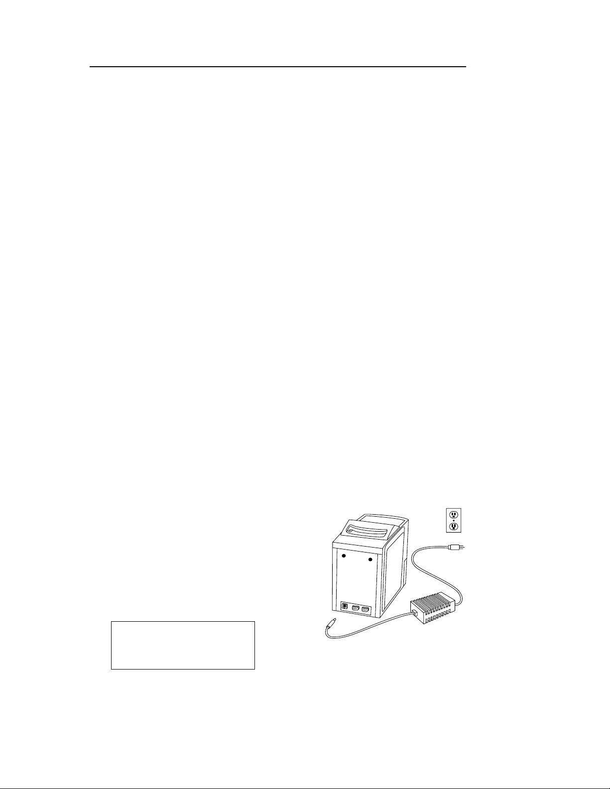
Step 1. Connect the power supply.
Refer to the figure at the right. Plug the DC
adapter into the socket on the back of the
analyzer . Connect the AC power cord to the
DC adapter. Plug the AC power cord into a
grounded
sage will appear on the display. The self-test
is described in
check all power supply connections.
electrical outlet. The self-test mes-
1.9.1
. If the display is blank,
grounded
electrical outlet.
Performing self-test
Piccolo Features and Components 1-9
Page 16

Piccolo Operator’s Manual
Step 2. Allow the analyzer to warm to operating temperature.
Depending on the ambient temperature, warming may take more time than the selftest.
⇒⇒⇒⇒ The analyzer is in standby mode, ie, ready to run a disc, when the display reads
Open drawer to run a
disc
Step 3. Check the date and time.
Check the analyzer date and time to ensure they ar e corr ect. Ref er to
date and time.
Step 4. Link the analyzer to an external computer. (Optional)
Refer to
1.11
.
Step 5. Perform control testing.
Per form one or more runs using recommended controls before running patient samples to confirm that the analyzer is functioning to specification. Refer to
run procedures.
3.2
to change the
2.4
for control
:
1.10.3 Powering down
The power should remain on unless you are moving the analyzer to a new location.
Always power down using the
The
key does not power down the analyzer when there is a reagent disc in the
POWER
drawer.
This message appears when the
shutdown procedure and return the analyzer to standby mode.
Turn analyzer off?
Press POWER to turn
off, or EXIT to
continue operation.
Press
again to initiate system shutdown. The analyzer turns off when the sys-
POWER
tem shutdown is complete.
Performing system
shutdown.
key rather than by unplugging the analyzer.
POWER
key is pressed. Press
POWER
to cancel the system
EXIT
#
1-10 Piccolo Features and Components
Page 17

Piccolo Operator’s Manual
1.11 Connecting to an external computer
An institution may wish to connect the analyzer to an external computer for any or all
of the following reasons: to incorporate testing data into patient records; to provide
records for regulatory compliance; or to connect with automated billing sys tems. The
instrument provides two RS232 ports for connection to external devices. Data from
the analyzer are exported to the external computer as text files (*.txt). Contact Abaxis
for technical support.
1.12 Consumables and ancillaries
Contact Abaxis or your authorized distributor to order reagent discs, result cards,
controls, and sample collection equipment and supplies.
1.13 Customer service and technical support
Call Abaxis Customer Service and Technical Support at 800-822-2947 with questions
®
regarding operation of and problems with the Piccolo
Analyzer.
Point-of-Care Chemistry
Piccolo Features and Components 1-11
Page 18

Page 19

Piccolo Operator’s Manual
Section 2: Testing Procedure and
Interpretation of Results
2.1 Sample requirements
• The Piccolo® Point-of-Care Chemistry Analyzer accepts heparinized whole blood,
heparinized pla s ma, or serum samples.
• Lithium heparin is the only anticoagulant recommended for use with the Piccolo
Point-of-Care Chemistry Analyzer.
• A sample size of 90–120µL is required.
• Whole blo od must be analyzed within 60 minutes of collection, or separated into
plasma or serum.
• To prevent hemolysis, do not refrigerate or shake whole blood.
• If not analyzed immediately, plasma or serum may be stored at room temperature
for no longer than 5 hours after centrifugation. If storage for more than 5 hours is
required, the sample should be refrigerated in the stoppered tube at 2– 8°C
(36– 46°F) for no longer than 48 hours; or stored at −10°C for up to 5 weeks in a
freezer without a self-defrost cycle. Under these conditions, there will be no clinically important changes in most analy te concentrations.
• For accurate interpretation of glucose results, the sample should be collected f rom
a patient who has fasted for at least 12 hours.
®
• Operator health and safety require that Universal Precautions be observed at all
times while handling hum an blood samples or working with the Piccolo® Pointof-Care Chemistry Analyzer in any way. The complete text of the document
“OSHA 29 CFR Part 1910, Occupational Exposure to Bloodborne Pathogens” can
be found on the Internet at www.osha-slc.gov/Preamble/Blood_toc_by_ sect.html.
2.2 Testing procedure
• Wear powder-free gloves while handling reagent discs or operating the analyzer.
Powder may disrupt the optical components.
• If necessary , power up the analyzer befor e beginning the procedure. Th e power-up
procedure is described in
• Ensure that the ambient temperature is 15–32°C (59–90°F).
The analyzer is in standby mode, ie, ready to run a disc, when the display reads
•
Open drawer
to run a disc
1.10.2
.
:
Testing Procedure and Interpretation of Results 2-1
Page 20
Piccolo Operator’s Manual
Write Patient ID
Here
90 µL
> 90 µL
< 120 µL
<90 µL
> 120 µL
2.2.1 Preparing the reagent disc
• Refer to
dling instructions. Please become thoroughly familiar with this information before
beginning the procedure.
1.7
for complete information about Piccolo ® reagent discs, in clud ing han-
• Refer to
2.1
for sample handling and storage requirements.
• The analysis must begin immediately (no more than 10 minutes) after dispensing
the sample into the reagent disc.
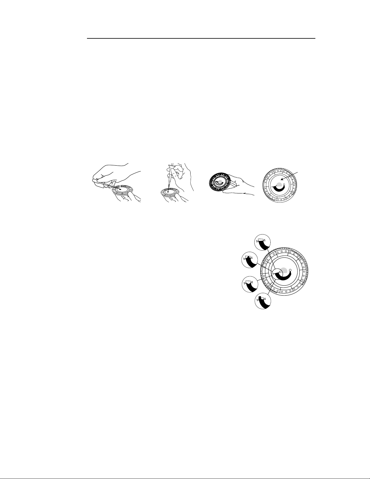
Step 1. Dispense the sample.
Use a micropipette or other transfer device to dispense approximately 100 µL of sample into the disc via the sample port.
a. Fill the sample port.
Expel air bubbles from the tip of the micropipette. Place the micropipette in the sample port
and tilt it until it is perpendicular to the disc
surface. Push down on the plunger with a slow,
continuous motion.
Take care not to overfill the sample chamber. A
90 µL sample will fill the sample chamber and
form a line between the two arrows molded on
the disc. More than 120 µL of sample will overfill the chamber. Discard the pipette tip into a
biohazard container.
b. Fill the sample chamber.
Tilt the disc to 45° with the sample port above the fill line, so that the entire sample flows into the sample chamber. Clean the reagent disc. Use a lint-fr ee tis sue to
remove any sample spilled on the outside of the disc, taking care that the tissue
does not withdraw any sample from the sample port. Dispose of the tissue in a
biohazard container.
c. (Optional) Label the disc.
Write the patient
on the disc surface in the space indicated in the figure above.
ID
Do not write anywhere else on the disc or on the bar code ring.
d. Carry the prepared disc to the analyzer.
Hold the disc by its edges in a flat position.
2-2 Testing Procedure and Interpretation of Results
Page 21
Piccolo Operator’s Manual
2.2.2 Running a patient sample
• The analyzer must be in standby mode to begin the procedure.
• Use the numeric and arrow keys to enter patient, operator , and physician
ID
the analysis is proceeding. The → key inserts a dash; the ← key deletes the character to the left.
• The reference range set and patient, operator, and physician
s must be entered
ID
before results can be calculated. If you wait until the run is complete before entering these numbers, the analyzer will require an additional one minute to calculate
the results.
• If an error message is displa yed at any time during the run, refer to
5.6
for trouble-
shooting procedures associated with the specific error code.
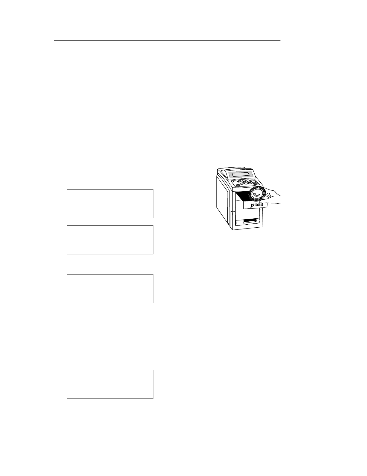
Step 2. Open the drawer and insert the disc .
Press
. The following messages are displayed sequen-
OPEN
tially:
Opening drawer...
Close drawer to start
analysis.
s while
Place the disc in the drawer. Press
Closing drawer...
. The display reads:
CLOSE
The analysis begins when the drawer closes.
Step 3. Select the reference range set.
By default, the reference range set for the previous sample is displayed. The reference
range set for the current sample must be selected for correct interpretation of results.
Use the numeric keys to select the correct reference range set. Press enter when the
correct number appears to the right of
Select Set:_ X
1- Male 2- Female
3- Special
ENTER to accept.
Select Set
.
Testing Procedure and Interpretation of Results 2-3
Page 22

Piccolo Operator’s Manual
Step 4. Enter the patient
A patient
(up to 14 characters) must be entered to continue. Press
ID
Input Patient #:
_ _ _ _ _ _ _ _
ENTER when finished.
Step 5. Enter the operator
By default, the operator
.
ID
.
ID
for the previous sample is displayed. Enter the operator ID
ID
for the current sample, up to 3 characters. Press
Input Operator #: XXX
ENTER when finished.
Step 6. Enter the physician
By default, the physician
for the current sample, up to 3 characters. Press
ID
Input DR #:
XXX
ENTER when finished.
.
ID
for the previous sample is displayed. Enter the physician
ID
ENTER
ENTER
.
ENTER
.
.
Step 7. Automatic sample processing.
The analyzer processes the sample and calculates results in less tha n 15 minutes with
no further operator input. During the run, the analyzer displays the following mes-
sage, including time remaining to complete the analysis (
Results ready in
XX:XX
for patient #:
XXXXXXXXXXXXXX
XX:XX
) and patient ID.
Sample processing is complete when the analyzer beeps and disp lays the message:
Analysis complete.
Open drawer or
insert card
to print results.
Step 8. Print results.
To end the procedure without printing results, press
If a Run Cancelled error message is displayed, refer to
ther instructions.
#
and continue to step 9.
OPEN
5.6
for an exp l anation and fur-
2-4 Testing Procedure and Interpretation of Results
Page 23

Piccolo Operator’s Manual
Place the result card in the result card slot. Remove the card when directed to do so on
the display. These messages appear sequentially:
Printing results...
Remove card.
Opening drawer...
Remove disc and close
drawer.
Step 9. Return the analyzer to standby mode.
Remove the reagent disc from the drawer and dispose of it, following your lab’s biohazard procedures. Press
to return the analyzer to standby mode.
CLOSE
2.2.3 Canceling an analysis in progress
Press
the analysis should be canceled:
Press
to cancel an analysis in progress. The display requests verification that
POWER
Cancel analysis?
Press POWER to cancel
run, or EXIT to continue analysis.
again to cancel the analysis. These messages appear sequentially:
POWER
Analysis canceled.
Opening drawer...
Testing Procedure and Interpretation of Results 2-5
Page 24

Piccolo Operator’s Manual
Remove disc and
close drawer.
Remove the reagent disc from the drawer. Press
to retu r n the analyzer to
CLOSE
standby mode.
For the run cancellation to take effect, the operator must press
before the ana-
POWER
lyzer has calculated the results. If the cancellation procedure is initiated after the analyzer has calculated the results, the cancellation will not take effect. The results are
stored in memory and can be printed. The
Analysis complete
message appears.
Continue from st ep 8, above.
Analysis complete.
Open drawer or insert
card to print results.
2.3 Interpreting patient results
Results are stored in internal memory, and, if the analyzer is connected to an external
computer, automatically tr ansmitted. Results can be printed on a result card. Refer to
2.2.2
, Step 8. An adhesive backing allows the result card to be placed in the patient’s
chart and become part of their permanent medical record. Refer to
mation about the result card. Follow your lab or institution’s procedure for transferring the card to the patient’s chart.
2.3.1 Reading the result card
result card heading
The
• test date and time
• reference range set
• pat ient, operator, and physician
• reagent disc type and lot number
• analyzer serial number.
test results section
The
• analyte
• ana lyte concentration
• reference range in specified units.
An asterisk (*) printed to the right of the analyte concentration in dica tes
side the reference range
includes:
s; or control level
ID
of the card is printed in three columns:
.
1.8
for basic infor-
results out-
A greater than (>) or less than (<) symbol printed to the left of the value in the analyte concentration column indicates
Refer to
A row of diamonds (
pressed results
2.3.2 A.
, below.
♦♦♦
. Refer to
) printed in place of analyte concentration indicates
2.3.2 B.
results outside the dynamic range
below.
of the assay.
sup-
2-6 Testing Procedure and Interpretation of Results
Page 25

Piccolo Operator’s Manual
HEM, LIP
affected by
by hemolysis and either or both of the other interferents,
result is affected by both lipemia and icterus,
indices printed at the bottom of the card to determine if more than one interferent is
affecting results. Refer to
INST QC: OK and CHEM QC: OK
when iQC testing indicates that all ins trume nt, d isc, and chemistry parameters meet
specifications.
Sample indices for hemolysis, lipemia, and icterus
card. The sample is rated for these interferents on the following scale:
0
clear
1+
slight
2+
moderate
3+
gross
ICT
, or
interference from hemolysis, lipemia, or icterus
is printed in place of the analyte concentration when results are
LIP
is printed. Examine the sample
2.3.2 C.
below for further instructions.
printed near the bottom of the result card
are printed at the bottom of the
. When a result is affected
HEM
is printed. When a
2.3.2 Abnormal results: interpretation and further action
A. Results outside the dynamic range
Refer to the disc package insert for information about the dynamic range of any assay
included in the disc. When the sample concentration falls below or exceeds the
dynamic range of the assay, the analyzer cannot calculate the concentration. The
numeric value that appears in the analyte concentration column is the upper or lower
limit of the dynamic range of the assay, preceded by > or < , respectively. For example,
the dynamic range of glucose is 10–700 mG/DL; a sample concentration of glucose
below this range would be printed as
cose above this range wou ld be printed as
<10 mG/DL
>700 mG/DL
; a sample concentration of glu-
.
Results outside the dynamic range should be reported as below or above the value
indicated.
B. Suppressed results
A result may be suppressed (ie, not held in memory and not able to be printed) when
any of the internal QC steps detect an abnormal condition.
Collect a new sample and rerun the test . If results f or the second sample are suppressed, call Abaxis Technical Support for further assistance.
(
♦♦♦
)
C. Interferents
The limits for physical interferents are given in the Piccolo reagent disc package
insert.
Testing Procedure and Interpretation of Results 2-7
Page 26

Piccolo Operator’s Manual
When the sample is hemolytic, collect a new sample and rerun the test. Abaxis recommends that the new sample be separated into serum or plasma so that th e degree of
hemolysis can be verified. If the new sample is hemolytic, use an alternati ve testing
method or send the sample to a reference laboratory.
Samples with hematocrit in excess of 60% packed red cell volume may be reported on
the result card as
HEM
. Follow the instructions above for retesting hemolyzed sam-
ples.
Lipemia may be due to diet. The patient should be instructed to fast for at least 10 to
12 hours before another sample is collected. For grossly lipemic samples from fasting
patients or for icteric samples, use an alternative testing method or send the sample to
a reference labora tory.
2.4 Running controls
Abaxis recommends control testing as follows:
• at least every 30 days
• whe never laboratory conditions have changed significantly
• when training or retraining of personnel is ind i c ated
• when test results do not match patient symptoms or clinical findings
Good laboratory practices include the recording of the QC data according to the labo-
ratory’s established written procedures. A permanent record of control results should
be retained.
Samples and controls are run identically by the analyzer. However, using the Run
Controls option in the Menu function stores control results separately from patient
results in the analyzer memory. Control results can be printed on a result card immediately after the conclusion of the control run, or whenever the control run results are
recalled. Refer to Section 4 for the use of the
RECALL
key. Control results are automati-
cally transmitted to a linked computer.
Handle the control as described in the control package insert. Call Abaxis Technical
support for assistance in interpreting control results.
Step 1. Prepare the reagent disc.
Use a micropipette or other transfer device to dispense approximately 100 µL of control into the sample port. Refer to
2.2.1
for detailed instructions on preparing the
reagent disc.
Step 2. Activate the Run Controls function.
Press
one time. Press
MENU
Press ENTER to
run controls,
MENU for next option
EXIT to leave.
ENTER
.
2-8 Testing Procedure and Interpretation of Results
Page 27

Piccolo Operator’s Manual
Step 3. Choose the correct control level.
By default, the display shows the control level for the previous control run. Use the
numeric keys to choose the correct control level for the current run. Press
Select level: xxx
1- I3-III
2- II
ENTER to accept.
ENTER
.
Step 4. Enter the operator
By default, the display shows the operator
operator
for the current control run, up to 3 characters. Press
ID
Input Operator #: XXX
ENTER when finished.
Step 5. Enter the physician
By default, the display shows the ph ysician
physician
for the current run, up to 3 characters. Press
ID
Input DR #:
XXX
ENTER when finished.
ID
ID
.
for the previous control run. Enter the
ID
.
ENTER
.
for the previous control run. Enter the
ID
.
ENTER
Step 6. Insert the prepared disc.
Following step 5, the drawer opens and the following messages are displayed sequentially:
Opening drawer...
Close drawer to start
analysis.
Control Level xxx
Insert the disc. Press close. This message appears briefly:
Closing drawer
Testing Procedure and Interpretation of Results 2-9
Page 28

Piccolo Operator’s Manual
Step 7. Automatic control processing.
The analyzer displays the control level and time remaining to compl e te the analysis.
Results ready in XX:XX
for control: Level XXX
When the analysis is complete, the analyz er beeps and displays the message:
Analysis complete. Open
drawer or insert card
to print results.
Step 8. Print control results.
If you choose not to print the results immediately following the control run, press
and continue with step 9.
OPEN
To print results immediately following the control run, insert a result card into the
slot. This message is displayed while results a re printing:
Printing results. . .
Remove the result card when directed to do so on the display. After the result card is
removed, the drawer opens automatically. Proceed to step 9.
Remove card.
Step 9. Return the analyzer to standby mode.
Remove the reagent disc from the drawer and dispose of it according to your lab’s
standard procedures. Press
. The analyzer returns to standby mode.
CLOSE
2.5 Limitations of the procedure
• Refer to
5.6
when error messages are displayed.
• Samples with hematocrit in excess of 60% packed red cell volume may be reported
on t he result card as
HEM
. Refer to
2.3.2 C.
• The ana lyzer suppresses results when the precision is signif icantly affected by
hemolysis, lipemia, or icterus. Refer to
2.3.2 C.
for instructions.
2-10 Testing Procedure and Interpretation of Results
Page 29

Piccolo Operator’s Manual
Section 3: The Menu Function
Several special functions programmed into the Piccolo® Point- of-Care Chemistry
Analyzer are accessed through the
standby mode, ie, when no analysis is in progress and the drawer is closed. From
within any of these Menu funtions, press
twice to return to standby mode.
EXIT
MENU
key. You can access the Menu function from
to return to the previous display. Press
EXIT
Function
Run controls Run controls 1 time
Change date and time Set the date and time 2 times
Select date format Choose month/day/year or
day/month/year
Select time format Choose 12-hour or 24-hour clock 4 times
Select units Choose international units ( SI) or units
commonly used in the United States
Customize reference
ranges
Print reference ranges Print the reference ranges in a specified
Transmit reference
ranges
Vi ew analyz er
Escape from
function
ID
MENU
Change ref erence ranges from defaults
to ranges specific to the patient popula-
tion
reference range set
Transmit all the reference ranges stored
in memory to a linked computer
Vi ew the analyzer serial number and
software version
EXIT
Description
Press
3 times
5 times
6 times
7 times
8 times
9 times
MENU
Refer to
2.4
3.2
3.3
3.4
3.5
3.6
3.7
3.8
3.9
3.1 Run controls
Refer to
stores control results in memory separate from the sample results, so you can use the
Recall function to search specifically for control results. In all other respects, controls
and samples are run identically by the analyzer.
The Menu Function 3-1
2.4
for the complete procedu re for running controls. This Menu function
Page 30

Piccolo Operator’s Manual
3.2 Change the date and time
The date and time are checked during the set up procedure. Refer to
1.10
. Change the
date or time format, if necessary, before changing the actual date or time. Refer to
3.4
and
Step 1. Press
.
twice to reach the Change Date and Time function:
MENU
Press ENTER to change
date & time,MENU for
next option EXIT to
leave
Step 2. Display the date or time in the active format.
Press
. Use the numeric keys 1 or 2 to choose date or time. Press
ENTER
Select: 2 Time
xx/xx/xxxx:xx MM
1- Date 2- Time
ENTER to accept.
ENTER
.
Step 3. Change the date.
← →
Use
and the numeric keys to enter the correct date. Press
to return to the
ENTER
screen in step 2.
Date:xx/xx/xx
0-9 keys to change,
to move cursor,
← →
ENTER to accept.
3.3
Step 4. Change the time.
← →
Use
If the 12-hour clock option is active, use
or
and the numeric keys to enter the correct time. Press
Time:xx:xx:xx MM
0-9 keys to change,
to move cursor,
← →
ENTER to accept.
← →
and the numeric keys 1 or 2 to select
PM
. Press
. (If the 24-hour clock is active, this option will not appear on the
ENTER
ENTER
.
AM
screen.)
Time:xx:xx:xx MM
1 for AM, 2 for PM
to move cursor,
← →
ENTER to accept.
3-2 The Menu Function
Page 31

Piccolo Operator’s Manual
If an invalid date (eg, 14 for the month) or time (eg, 30 for hours) has been entered, an
invalid entry message appears:
Entry for date was
invalid. Enter date
value again.
Press EXIT.
or
Entry for time was
invalid. Enter time
value again.
Press EXIT.
Press
to return to the screen shown in Step 3. or Step 4 ., wher e you can corr ect the
EXIT
date or time.
Step 5. Verify date and time settings.
When the date or time you entered is valid, the following scr een is displayed. To make
more changes, press either 1 or 2 and
Select: 2 Time
xx/xx/xx xx:xx MM
1- Date 2-Time
ENTER to accept.
. Repeat Step 3. or Step 4.
ENTER
Step 6. Return to standby mode.
EXIT
twice.
Press
The Menu Function 3-3
Page 32

Piccolo Operator’s Manual
3.3 Select date format
Two options are available: month/day/year and day/month/year.
Step 1. Press
Press ENTER to select
date format,
MENU for next option
EXIT to leave.
3 times to reach the Select Date Format function:
MENU
Step 2. Choose the date format.
Press
to display the active date format. To select the alternative format, press 1
ENTER
or 2 . The format you chose will be displayed. Press
Select:1 MM/DD/YY
1- MM/DD/YY 07/16/95
2- DD/MM/YY 16/07/95
ENTER to accept.
Step 3. Return to standby mode.
EXIT
.
Press
3.4 Select time format
Options are a 12-hour clock and a 24-hour clock.
Step 1. Press
4 times to reach the Select Time Format function:
MENU
ENTER
to accept.
Press ENTER to select
time format,
MENU for next option
EXIT to leave.
Step 2. Choose the time format.
Press
or 2. The format you chose will be displayed. Press
to display the active time format. To select the alternative format, press 1
ENTER
to accept.
ENTER
Select: xx hour
1- 12 hour 02:25 PM
2- 24 hour 14:25
ENTER to accept
Step 3. Return to standby mode.
Press
EXIT
twice
3-4 The Menu Function
Page 33

Piccolo Operator’s Manual
3.5 Select units
Options are common (eg, mg/dL) or SI (eg, mmol/L) units for reporting results.
Step 1. Press
Press ENTER to select
units,
MENU for next option
EXIT to leave.
5 times to reach the Select Units function.
MENU
Step 2. Accept or change the active option.
Press
alternative option. Press
. The display indicates which option is active. Press
ENTER
.
ENTER
Common Units
to change
← →
ENTER to accept.
or
SI (Int’l) units
to change
← →
ENTER to accept.
Step 3. Return to standby mode.
Press
EXIT
.
← →
to select the
The Menu Function 3-5
Page 34

Piccolo Operator’s Manual
3.6 Customize reference ranges
Change the default or existing reference ranges stor ed in the an alyzer to match the re ference ranges specific to the patient population.
NOTE: Change reference ranges in either c ommon units or SI units, not both. The analyz er
automatically converts units.
Step 1. Press
Press ENTER to edit
reference ranges,
MENU for next option
EXIT to leave.
6 times to reach the Change Reference Ranges function:
MENU
Step 2. Select the method (analyte).
Press
ENTER
. Use
← →
to choose a method (analyte) other than the one shown on the
display.
Select Method:
xxxxxxxxxxxxx
Press
ENTER to accept.
← →
to scan,
Step 3. Select the reference range set.
Use the numeric keys. Press
Select Set 1: MALE
1- Male 2- Female
3- Special
ENTER to accept.
ENTER
.
The method (analyte) and its current reference range set and values are displayed.
Method Gender Range
Units 0-9 keys to
change,ENTER to accept.
Step 4. Change the reference range set or values.
← →
Use
and the numeric keys. Press
to accept the changes. The analyzer
ENTER
returns to the screen displayed in Step 2.
Select Method:
xxxxxxxxxxxxx
← →
to scan,
Press
ENTER to accept.
3-6 The Menu Function
Page 35

Piccolo Operator’s Manual
Step 5. Correct errors.
If an invalid value has been entered, the following screen is displayed. Press
current reference range values will be restored. Repeat step 4 with valid data.
Reference range entry
not valid.
Press EXIT.
Step 6. Change the reference ranges for other methods (analytes).
Repeat steps 2-4.
Step 7. Print reference ranges.
Ve rify reference ranges by printing them on a result card. From the screen in Step 4.,
press
EXIT, MENU
to bring up the Print Reference Ranges menu option. (Refer to
The date and tim e shown on the card are the date and time the card was printed, not the date
and time the refer enc e ranges wer e chan ged. To record the date you changed th e ranges, write it
on the card.
Step 8. Return to standby mode.
Press
EXIT
twice.
EXIT
. The
3.7
.)
The Menu Function 3-7
Page 36

Piccolo Operator’s Manual
3.7 Print reference ranges
Print the reference ranges for a specific reference range set.
The date and time shown on
the card are the date and time the card was printed, not the date and time the reference ranges
were changed. To record the date you changed the ranges, write the information on the card.
Step 1. Press
Press ENTER to print
reference ranges,
MENU for next option
EXIT to leave.
7 times to reach the Print Reference Ranges function:
MENU
Step 2. Select the reference range set to be printed.
Press
. Use the numeric keys. Press
ENTER
Select Set : ZZZZZ
1- Male 2- Female
3- Special
ENTER to accept.
ENTER
again
.
Step 3. Print.
Verify that the reference range set of interest is displayed. Inser t a result card. Follow
the instructions on the display:
Insert card to print
ZZZZZZZZ
reference ranges or
EXIT to quit.
Printing ranges.
Remove card
Step 4. Print additional reference ranges.
After the card is removed, the display returns to the screen in step 2. Repeat steps 2
and 3.
Step 5. Return to standby mode.
Press
EXIT
twice.
3-8 The Menu Function
Page 37

Piccolo Operator’s Manual
3.8 Transmit reference ranges
The reference ranges stored in the analyzer memory can be transmitted to a linked
computer.
reference ranges were changed.
computer.
The date and time recorded are those of the transmission, not the date and time the
Refer to
1.11
for instructions for linking to an external
Step 1. Press
ENTER to transmit
reference ranges,
MENU for next option
EXIT to leave.
8 times to reach the Transmit Reference Ranges function:
MENU
Step 2. Select the reference range set to transmit.
Press
. Use the numeric keys. Press
ENTER
Select Set: ZZZZZ
1- Male 2- Female
3- Special
ENTER to accept.
ENTER
again
.
During the transmission , th e display reads:
Transmitting ranges
to computer.
Step 3. Transmit additonal reference ranges
After transmission is complete, the display returns to the first screen in step 2. Repeat
step 2.
Step 4. Return to standby mode.
Press
EXIT
twice.
The Menu Function 3-9
Page 38

Piccolo Operator’s Manual
3.9 View analyzer identification
Step 1. Press
Press ENTER to view
analyzer ID,
MENU for next option
EXIT to leave.
9 times to reach the View Analyzer ID function:
MENU
Step 2. Display the serial number and software version.
Press
.
ENTER
Serial #:xxxxxxxxxxSoftware version:X.XXXPress ENTER.
Step 3. Return to standby mode.
Press
EXIT
twice.
3-10 The Menu Function
Page 39

Section 4: The Recall Function
Piccolo Operator’s Manual
The
RECALL
key allows access to patient results, control results, and system QC data
stored in the analyzer memory. The analyzer memory stores the results for the last 150
patient samples and the last 75 control samples, in reverse chronological order. (Refer
1.9
to
for information about system QC data.) Results or system QC for a specified
sample or control that remains in memory can be recalled using run-specific parameters, or by scanning the entries in chronological order.
Note that results stored on an external computer must be accessed through the computer.
The Recall function can be accessed whenever the analyzer is in standby mode. It cannot be accessed from the Menu functions. Press
at any time while in the Recall
EXIT
function to return to the previous display.
• Use the numeric and arrow keys to enter patient, operator, and physician
ID
s.
The → key functions as a dash; the ← key functions as a backspace (delete key).
•The message
No results in memory
may be displayed after the analyzer
memory has been cleared during servicing. If it is displayed at any other time,
refer to
code number is displayed, refer to
5.6
for troubleshooting procedur es under the error code number. If no err or
4.11
or
4.12
4.1 Scanning patient results in chronological order
Step 1. Access the Recall function.
From standby mode, press
RECALL
. The display reads:
Recall: 1 Results
1-Results
2-System QC
ENTER to accept.
Step 2. Access Results.
Press 1,
. The display reads:
ENTER
Recall: 1 Patient
1-Patient Results
2-Control Results
ENTER to accept.
The Recall Function 4-1
Page 40

Piccolo Operator’s Manual
Step 3. Choose the results set of interest.
Press 1,
Step 4. Accept the print option.
Press 1,
played.
Step 5. Scan patient results.
← →
Use
nological order. The analyzer beeps twice when you have reached either end of the
list. To exit without printing results, press
for patient results. The display reads:
ENTER
Select: 1 Print
1-Print result card
2-Transmit result
ENTER to accept
. By default, the patient ID, date, and time of the most recent run are dis-
ENTER
Pt # XXXXXXXXXXXX
xx/xx/xx xx:xx
to view results,
← →
ENTER to print.
to view the results in sequence. Patient results are retrieved in reverse chro-
three times to return to standby mode.
EXIT
Step 6. Print patient results.
When the result of interest is displayed, press
. (Data are automatically transmit-
ENTER
ted to a linked computer.)#The following messages are displayed sequentially:
Insert card to print
results.
Printing results...
Remove card.
Step 7. Scan more patient results.
When the card is removed, the display returns to the screen in step 4. Repeat steps 5
and 6.
Step 8. Return to standby mode.
Press
three times.
EXIT
4-2 The Recall Function
Page 41

Piccolo Operator’s Manual
4.2 Recalling results by specifying patient ID
Step 1. Access the Recall function.
From standby mode, press
Recall: 1 Results
1-Results
2-System QC
ENTER to accept.
RECALL
Step 2. Access Results.
Press 1,
. The display reads:
ENTER
Recall: 1 Patient
1-Patient Results
2-Control Results
ENTER to accept.
Step 3. Choose the results set of interest.
Press 1 and
for patient results. The display reads:
ENTER
. The display reads:
Select: 1 Print
Print result card
Transmit result
ENTER to accept
Step 4. Accept the Print option.
Press 1,
. By default, the patient ID, date, and time of the most recent run are dis-
ENTER
played.
Pt # XXXXXXXXXXXX
xx/xx/xx xx:xx
to view results,
← →
ENTER to print.
Step 5. Specify the patient
Press
RECALL
. Key in the patient ID. Press
ID
.
memory for the specified patient
Search for patient #
XXXXXXXXXXXXXX
ENTER to search.
ID
. The analyzer retrieves all results in
ENTER
.
The Recall Function 4-3
Page 42

Piccolo Operator’s Manual
a. If no
Press
step 5 using a different patient ID; or press
b. If
The total number of matches (runs) found for the specified patient
by
ical order . For example, “
and the most recent of these is selected. Use
patient
matches
ENTER
one or more matches
ttt
. Individual matches, represented by
. To exit without printing results for any run in this set, press
ID
are found for the specified patient
Pt # XXXXXXXXXXXXXX
not found
Press ENTER.
, the display reads:
ID
to return to the screen in step 4. V erify that the patient ID is corre ct. Repeat
three times to return to standby mode.
EXIT
are found, the display reads:
Pt # XXXXXXXXXXXX
xx/xx/xx xx:xx
nnn of ttt,
ENTER to print.
to view
← →
1 of 3
nnn,
are numbered in reverse chronolog-
” means three matches were found for this patient
← →
to scan other matches for this
is represented
ID
EXIT
to the screen in step 4. Repeat step 5 using a different patient ID; or press
times to return to standby mode.
to return
three
EXIT
ID
,
Step 6. Print patient results.
When the result of interest is displayed, press
. (The data are automatically
ENTER
transmitted to a linked computer.)#The following messages are displayed sequentially:
Insert card to print
results.
Printing results...
Remove card.
Step 7. Retrieve results for a different patient
ID
.
When the card is removed, the display returns to the screen in step 4. Repeat steps 5–6.
4-4 The Recall Function
Page 43

Piccolo Operator’s Manual
Step 8. Return to standby mode.
Press
three times.
EXIT
4.3 Scanning control results in chronological order
Step 1. Access the Recall function.
From standby mode, press
Recall: 1 Results
1-Results
2-System QC
ENTER to accept.
Step 2. Access Results.
Press 1,
.
ENTER
Recall: 1 Patient
1-Patient Results
2-Control Results
ENTER to accept.
RECALL
. The display reads:
Step 3. Choose the results set of interest.
Press 2,
for control results. The display reads:
ENTER
Select: 1 Print
1-Print result card
2-Transmit result
ENTER to accept
Step 4. Accept the Print option.
Press 1,
. By default, the control level, date, and time of the most recent control
ENTER
run are displayed.
Control level: XXX
xx/xx/xx xx:xx
to view results,
←,→
ENTER to print.
Step 5. Scan control results.
← →
← →
Use
to view the results of other con trol runs. Control run data are retrieved in
← → ← →
reverse chronological order. The analyzer beeps twice when you have reached either
end of the list. To exit without printing control r esults, press
three times to return
EXIT
to standby mode.
The Recall Function 4-5
Page 44

Piccolo Operator’s Manual
Step 6. Print control results.
When the control run of interest is displayed, pr ess
sages are displayed sequentially:
Insert card
to print results.
Printing results...
Remove card.
Step 7. Scan more control results.
When the card is removed, the analyzer r eturns to the dis play in step 4. Repeat steps 5
and 6.
to print. The following mes-
ENTER
Step 8. Return to standby mode.
Press
three times.
EXIT
4.4 Recalling a specific control result
Step 1. Access the Recall function.
From standby mode, press
Recall: 1 Results
1-Results
2-System QC
ENTER to accept.
Step 2. Access Results.
Press 1,
. The display reads:
ENTER
Recall: 1 Patient
1-Patient Results
2-Control Results
ENTER to accept.
RECALL
. The display reads:
4-6 The Recall Function
Page 45

Piccolo Operator’s Manual
Step 3. Choose the results set of interest.
Press 2,
Step 4. Accept the Print option.
Press
ENTER
are displayed.
Step 5. Specify the control run.
Press
RECALL
retrieves all control results in memory for the specified date.
for control results. The display reads:
ENTER
Select: 1 Print
Print result card
Transmit result
ENTER to accept
. By default, the control level, date, and time of the most recent control run
Control level:XXX
xx/xx/xx xx:xx
to view results,
←,→
ENTER to print.
. Key in the date of the control run of interest. Press
. The analyze r
ENTER
Search for control
results on xx/xx/xx
ENTER to print.
no matches
a. If
Press
ENTER
in another date or use
are found for the specified date, the display reads:
No control results
found on xx/xx/xx
Press ENTER.
to return to the screen in step 4. V erify that the date entered is correct. Key
← →
return to standby mode.
one or more matches
b. If
Control Level: XXX
xx/xx/xx xx:xx
nnn of ttt,←
ENTER to print.
to scan other control results; or press
are found, the display reads:
to view
→
three times to
EXIT
The Recall Function 4-7
Page 46

Piccolo Operator’s Manual
In the mes sage above,
specified date. Individual matches are represented by
ttt
represents the total number of control runs found for the
nnn
. For example, “
1 of 3
means data on three control runs were found for this date, and the first of these is
selected. Use
run in this set, press
← →
to scan the other matches. To exit without printing results for any
and enter another date, or press
EXIT
three times to return to
EXIT
standby mode.
Step 6. Print control results.
When the result of interest is displayed, press
. The following messages are dis-
ENTER
played sequentially.
Insert card
to print results.
Printing results...
Remove card.
”
Step 7. Retrieve more control results .
When the card is removed, the display returns to the screen in step 4. Repeat steps 5
and 6.
Step 8. Return to standby mode.
Press
three times.
EXIT
4.5 Scanning system QC data associated with patient results in chronological order
Step 1. Access the Recall function.
From standby mode, press
Recall: _XXXXXXX
1-Results
2-System QC
ENTER to accept.
RECALL
. The display reads:
4-8 The Recall Function
Page 47

Step 2. Access System QC.
Press 2,
.
ENTER
Recall: _XXXXXXXX
1-Patient Set
2-Control Set
ENTER to accept.
Step 3. Choose the results set of interest.
Press 1,
for patient set. The display reads:
ENTER
Select: 1 Print
1-Print System QC
2-Transmit System QC
ENTER to accept
Step 4. Accept the Print System QC option.
Press
. By default, the patient ID, date, and time of the most recent run ar e displayed.
ENTER
Pt # XXXXXXXXXXXX
xx/xx/xx xx:xx
to view results,
← →
ENTER to print.
Piccolo Operator’s Manual
Step 5. Scan patient results.
← →
← →
Use
either end of the list. To exit without printing results, press
to view patient results in chronological order. The analyzer beeps twice at
← → ← →
three times to return
EXIT
to standby mode.
Step 6. Print System QC results.
When the result of interest is displayed, press
. (System QC data associated with
ENTER
that result are automatically transmitted to a linked computer.) The following messages are displayed sequentially:
Insert card to print
results.
Printing results...
The Recall Function 4-9
Page 48

Piccolo Operator’s Manual
Remove card.
Step 7. Scan more patient results.
When the card is removed, the display returns to the screen in step 4. Repeat steps 5
and 6.
Step 8. Return to standby mode.
Press
three times.
EXIT
4.6 Recalling system QC data associated with patient
results by specifying patient
Step 1. Access the Recall function.
From standby mode, press
RECALL
. The display reads:
ID
Recall: _XXXXXXX
1-Results
2-System QC
ENTER to accept.
Step 2. Access system QC.
Press 2,
.
ENTER
Recall: _XXXXXXXX
1-Patient Set
2-Control Set
ENTER to accept.
Step 3. Choose the results set of interest.
Press 1,
for patient set. The display reads:
ENTER
Select: 1 Print
1-Print System QC
2-Transmit System QC
ENTER to accept
Step 4. Accept the Print System QC option.
Press
. By default, the patient ID, date, and time of the most recent run ar e displayed.
ENTER
Pt # XXXXXXXXXXXX
xx/xx/xx xx:xx
to view results,
← →
ENTER to print.
4-10 The Recall Function
Page 49

Piccolo Operator’s Manual
Step 5. Specify the patient
Press
RECALL
. Enter the patientID. Press
ID
.
memory for the specified patient
Search for patient #
XXXXXXXXXXXXXX
ENTER to search.
no matches
a. If
Press
ENTER
specify a different patient
were found for the specified patient
Pt # XXXXXXXXXXXX
not found
Press ENTER.
to return to the screen in step 4. Verify that the patient ID is correct. To
, repeat step 5. Press
ID
mode.
one or more matches
b. If
Pt # XXXXXXXXXXXX
xx/xx/xx xx:xx
nnn of ttt,
ENTER to print.
are found, the display reads:
to view
← →
ID
. The analyzer retrieves all results in
ENTER
.
, the display reads:
ID
three times to return to standby
EXIT
The total number of matches found for the specified patient
Individual matches, represented by
order. For example, “
1 of 3
and the most recent of these is selected. Use
without printing results for any run in this set, press
step 4; or press
three times to return to standby mode.
EXIT
nnn,
are numbered in reverse chronological
” means three matches were found for this patient ID,
← →
to scan the other matches. To exit
to return to the screen in
EXIT
Step 6. Print system QC data.
When the run of interest is selected, press
. The following messages are dis-
ENTER
played sequentially:
Insert card to print
results.
Printing results...
is represented by
ID
ttt
.
The Recall Function 4-11
Page 50

Piccolo Operator’s Manual
Remove card.
Step 7. Retrieve results for a different patient
ID
.
When the card is removed, the display returns to the screen in step 4. Repeat steps 5–6.
Step 8. Return to standby mode.
Press
three times.
EXIT
4.7 Scanning system QC data associated with control results in chronological order
Step 1. Access the Recall function.
From standby mode, press
Recall: _XXXXXXX
1-Results
2-System QC
ENTER to accept.
Step 2. Access System QC.
Press 2,
. The display reads:
ENTER
Recall: _XXXXXXXX
1-Patient Set
2-Control Set
ENTER to accept.
RECALL
. The display reads:
Step 3. Choose the results set of interest.
Press 2,
for control results. The display reads:
ENTER
Select: 1 Print
1-Print System QC
2-Transmit System QC
ENTER to accept
Step 4. Accept the Print System QC option.
Press
. By default, the control level, date, and time of the most recent control run
ENTER
are displayed.
Control level: XXX
xx/xx/xx xx:xx
to view results,
←,→
ENTER to print.
4-12 The Recall Function
Page 51

Piccolo Operator’s Manual
Step 5. Scan system QC results.
← →
← →
Use
lyzer beeps twice at either end of the list. T o exit without printing control results, press
EXIT
Step 6. Print System QC results.
When the control result of interest is displayed, press
are displayed sequentially:
to view the results of control runs in reverse chronological order. The ana-
← → ← →
three times to return to standby mode.
. The following messages
ENTER
Insert card to print
results.
Printing results...
Remove card.
Step 7. Scan other control results.
When the card is removed, the display returns to the screen in step 4. Repeat steps 5
and 6.
Step 8. Return to standby mode.
Press
three times.
EXIT
4.8 Recalling system QC data associated with a specific control result
Step 1. Access the Recall function.
From standby mode, press
Recall: _ XXXXXXX
1-Results
2-System QC
ENTER to accept.
RECALL
. The display reads:
The Recall Function 4-13
Page 52

Piccolo Operator’s Manual
Step 2. Access System QC.
Press 2,
Step 3. Choose the results set of interest.
Press 2,
Step 4. Accept the Print System QC option.
Press
ENTER
most recent control run.
.
ENTER
Recall: _ XXXXXXX
1-Patient Set
2-Control Set
ENTER to accept.
for control results. The display reads:
ENTER
Select: 1 Print
1-Print System QC
2-Transmit System QC
ENTER to accept
. By default, the control level, date, and time displayed are those for the
Control level: XXX
xx/xx/xx xx:xx
to view QC,
←,→
ENTER to print.
Step 5. Specify the control run.
Press
RECALL
. Key in the date of the control run. Press
. The analyzer retrieves all
ENTER
control results in memory for the specified date.
Search for control
results on xx/xx/xx
Edit date,
ENTER to search.
no matches
a. If
Press
ENTER
are found with the requested date, the display reads:
No control results
found on xx/xx/xx
Press ENTER.
to return to the screen in step 4. Verify that the date specified is correct.
Use ← → to scan other control results. To exit without printing any system QC data,
press
three times to return to standby mode.
EXIT
4-14 The Recall Function
Page 53

one or more matches
b. If
Control Level:XXX
xx/xx/xx xx:xx
nnn of ttt,←
ENTER to print.
are found, the display reads:
to view
→
Piccolo Operator’s Manual
In the message above,
specified date. Individual runs are represented by
ttt
represents the total number of control runs found for the
nnn
. For example, “
1 of 3
”
means data on three control runs were found for this date, and the first of these is
selected. Use
run in this set, press
← →
to scan the other matches. To exit without printing results for any
to return to the screen in step 4; or press
EXIT
three times to
EXIT
return to standby mode.
Step 6. Print system QC data.
When the run of interest is selected. The following mes sages are displayed sequentially:
Insert card to print
results.
Printing results...
Remove card.
Step 7. Retrieve more control results .
When the card is removed, the display returns to the screen in step 4. Repeat steps 5
and 6.
Step 8. Return to standby mode.
Press
three times.
EXIT
The Recall Function 4-15
Page 54

Piccolo Operator’s Manual
4.9 Transmitting results to an external computer
If the analyzer is connected to an external computer, the results are automatically
transmitted when the result card is printed. Follow this procedure when you wish to
transmit all patient or control results currently stored in the analyzer memory to the
computer eg, before reinitializing the software or before returning the analyzer to
Abaxis for service. Refer to
Step 1. Access the Recall function.
From standby mode, press
Recall: _XXXXXXX
1-Results
2-System QC
ENTER to accept.
Step 2. Access the Transmit Results function.
Press 9,
even though this is not shown as an option on the display
Recall: 9 All Rslts
1-Results
2-System QC
ENTER to accept.
5.4
for information on reinitializing th e sof tware.
RECALL
. The display reads:
. Press
ENTER
.
Step 3. Choose results category.
Press 1,
to transmit all patient results or 2,
ENTER
to transmit all control results
ENTER
in memory. Up to two minutes may be required for all the results to be transmitted.
Recall: _XXXXXXXXXX
1-Patient Result
2-Control Result
ENTER to accept.
During the transmission , th e display reads:
Transmitting results...
When transmission is complete, the display returns to the screen in step 1.
Step 4. Return to standby mode.
Press
three times.
EXIT
4-16 The Recall Function
Page 55

Piccolo Operator’s Manual
4.10 Transmitting system QC data to an external computer
Step 1. Access the Recall function.
From standby mode, press RECALL. The display reads:
Recall: _XXXXXXX
1-Results
2-System QC
ENTER to accept.
Step 2. Access the Transmit System QC function.
Press 6,
Step 3. Choose the set to transmit.
Press 1,
trol system QC data in memory. Up to two minutes may be required for all the results
to be transmitted.
even though this is not shown as an option on the display
Recall: 6 All QC
1-Results
2-System QC
ENTER to accept.
to transmit all patient system QC data, or 2,
ENTER
. Press
ENTER
to transmit all con-
ENTER
.
Recall: _ XXXXXXX
1-Patient Set
2-Control Set
ENTER to accept.
During the transmission , th e display reads:
Transmitting results...
When transmission is complete, the display reads:
Recall: _ XXXXX
1-Patient Results
2-Control Results
ENTER to accept.
Step 4. Return to standby mode.
Press
three times.
EXIT
The Recall Function 4-17
Page 56

Piccolo Operator’s Manual
4.11 No results in memory
The message
No results found in memory
may be displayed if the analyzer’s
memory has been cleared during servicing.
Step 1. Return to the Recall screen.
Press
. Verify that both patient results and control results are missing from the
ENTER
analyzer memory.
Recall: _XXXXXXXX
1-Patient Results
2-Control Results
ENTER to accept.
Step 2. Return to standby mode.
Press
three times.
EXIT
4.12 No system QC in memory
In step 3 of the procedure in
4.5, 4.6, 4.7
informing you that there are no patient or control system QC data currently available
in the analyzer memory. Press
to return to the Recall screen.
ENTER
Ve rify that both patient and control system QC data are missing from the analyzer
memory.
Recall: _XXXXXXXX
1-Patient Results
2-Control Results
ENTER to accept.
, or
4.8
, the analyzer may display a message
Step 3. Return to standby mode.
Press
three times.
EXIT
4-18 The Recall Function
Page 57

Piccolo Operator’s Manual
Section 5: Maintenance and Troubleshooting
5.1 Routine maintenance
The Piccolo® Point-of-Care Chemistry Analyzer requires no scheduled servicing.
Maintenance of the analyzer is lim ited to:
• cleaning the exterior weekly, or as needed
• cleaning the printer and results card slot every 3 months
• cleaning the air filter every 6 months
Biohazard: The interior of the analyzer should be considered contaminated after the
first sample or control has been run.
5.1.1 Cleaning the exterior
Clean the outside surface of the analyzer at least every week and immediately after
sample, reagent, or other material has been spilled on it. Clean the analyzer w ith a soft
cloth dampened with a mild detergent or cleaning solution, or a 10% bleach solution
(1 part bleach to 9 parts water), or a 30% isopropyl alcohol solution. Do not spray or
pour detergents or other solution directly onto the analyzer. Wipe the entire surface of
the analyzer, including the keypad. Observe Universal Precautions when cleaning
spills.
5.1.2 Cleaning the printer
The printer should be cleaned at least once every 3 months to avoid paper jams and
printer malfunctions. Dust, debris, hair, or objects may become deposited in the result
card slot during the course of operation. If more than one attempt is required to feed a
card into the slot, the printer may require cleaning.
Procedure:
sweeping from right to left, pausing momentarily, then sweeping back to the right. It
is important to direct a stream of air into the left side of the slot to clear any debris
from the print sensor.
If the problem persists, a more thorough cleaning may be required. Access the printer
follow the instructions for clearing a paper jam; then expel compressed air directly
into the printer. Contact Abaxis Technical Support for further assistance.
Expel a steady stream of compressed air directly into the results card slot ,
Maintenance and Troubleshooting 5-1
Page 58

Piccolo Operator’s Manual
5.1.3 Cleaning the air filter
The air filter should be cleaned at least once every 6 months. Check the air filter more
frequently if the analyzer is in a dusty environment. To clean the air filter:
Step 1. Remove the filter.
Power down the analyzer and unplug the power cord from the back panel. Remove
the back panel by removing the two Phillips screws at the top of the panel. Grasp the
black mesh filter in the circular opening and pull the filter free.
Step 2. Wash the filter.
Use warm soapy water. Dry the filter thoroughly before replacing it in the an alyzer.
Step 3. Replace the filter.
Tuck the sides in behind the edges of the circular opening. Replace the rear panel.
Step 4. Power up the analyzer.
Reconnect the analyzer to the power supply and plug it in. Th e analyzer returns to
standby mode.
If the analyzer reports an error, repeat the installation procedure. If the error persists,
call Abaxis Technical Support.
5-2 Maintenance and Troubleshooting
Page 59

Piccolo Operator’s Manual
5.2 Clearing a paper jam
If a results card becomes jammed in the printer, you can open the analyzer front panel
and remove the card.
Step 1. Access the printer.
Open the disc drawer. Power down the analyzer and unplug the power cord from the
back panel. Open the front panel by placing your thumbs at points A and B shown in
the figure below. Grasp slot C on both sides of the front panel with yo ur fingers a nd
pull the panel toward you. (The panel is hinged at the bottom.) The prin ter is visible
when the front panel is open.
POPO
WER
W
E
R
7
8
9
R
RECALL
E
C
A
L
L
4
5
6
M
MENU
E
N
U
1
2
3
E
EXIT
O
OPEN
X
I
P
T
E
N
C
CLOSE
L
O
S
E
0
E
ENTER
N
T
E
R
AB
C
201 9009
Step 2. Remove the jammed card.
Lift the printer-head lever located on the right side of the printer, as shown in the figure above. Carefully r emove the jammed r esult car d. Push the printer- head lever back
down to its normal position. Press the front panel firmly into the closed position.
Step 3. Power up the analyzer.
Reconnect the analyzer to the power supply and plug it in. Th e analyzer returns to
standby mode.
Maintenance and Troubleshooting 5-3
Page 60

Piccolo Operator’s Manual
Figure 5-1
5.3 Installing a software card
From time to time, Abaxis will provide software cards to update and add functionality to the analyzer. To install a software card:
Step 1. Remove the existing software card.
Power down the analyzer and unplug the power cord from the back panel. Remove
the back panel by removing the two Phillips screws at the top of the panel. Remove
the software card retaining bracket by removing the Phillips screw. T a ke car e to avoid
losing this very small screw. To eject the card, push the black button at the top of the
access slot. Refer to the figures below.
Step 2. Insert the new software card.
Insert the new card with the printed label facing toward the
center of the analyzer Refer to the figure to the right. Push
the card in firmly until it clicks into place. Replace the
retaining bracket and back panel.
Step 3. Automatic reprogramming.
Power up the analyzer. It performs the self-test and reprogramming in about 10 minutes. Additional time may be
required for the analyzer to reach operating temperature.
The procedure is complete when the analyzer returns to
standby mode.
If the analyzer reports an error, repeat the installation procedure, verifying that the new card is seated properly. If the
error persists, call Abaxis Tech nical Support.
5-4 Maintenance and Troubleshooting
Page 61

Piccolo Operator’s Manual
5.4 Reinitializing the analyzer
Reinitializing the analyz er m ay become necessary if the software becomes corrupted.
A Code 28 error message is a warning that the software has b ecome corrupted and
must be reinitialized.
The reinitializing process clears all results from memory and deletes all customized
reference ranges.
and control results in memory following the procedures in
remain in memory, and the analyzer is linked to an external computer, follow the
instructions to transmit all patient and control results (
respectively, to the external computer before reinitializing the software. If results
remain in memory, and the analyzer is not linked to an external computer, print all
records (patient, control, and system QC results) that you wish to retain, following the
procedures in
customized reference ranges.
After receiving a Code 28 message, check the status of the patient
Section 4
. Follow the procedure in
3.7
and/or
4.1
4.9
) and system QC data (
4.3
and
3.8
. If results
to print or transmit
4.10
),
Reinitializing restores all defaults. Refer to
Section 3
for procedures for changing the
date and time, selecting units, and customizing reference ranges.
Step 1. Access the Reset function.
From standby mode, press 0.
RESET
Internal Clock
CLEARING memory
ENTER to accept
Step 2. Verify intention to reset.
Press
. The display reads:
ENTER
Are you sure you want
to reset?
ENTER for yes
EXIT for no
Step 3. Begin reinitialization.
Press
again. During the reinitialization process, the displa y reads:
ENTER
Resetting clock ...
Clearing Memory ...
5.5 Returning the analyzer to Abaxis for service
If the procedures in Maintenance and Troubleshooting fail to resolve a problem with
the operation of the analyzer, call Abaxis Technical Support. Authorization from Technical Support is required before returning an analyzer for repairs.
Maintenance and Troubleshooting 5-5
Page 62

Piccolo Operator’s Manual
5.6 Error messages
The following list of warnings and error messages is in order by error code number.
Some error codes include an internal error code number displayed flush left on the
4th line of the display. Record this internal error code number before pressing
calling Abaxis Technical Support. The number helps Technical Support to diagnose
the problem. Some error messages generate a troubleshooting report in addition to the
error code. Print the troubleshooting report befor e pre ssing
and the troubleshooting report, if applicable, at hand when calling Abaxis Technica l
Support.
. Have any error codes
EXIT
EXIT
or
Error Message Explanation and Solution
Code 10
Run canceled: Barcode
error. Repeat run with
new disc.
xxxx See Code 10
Code 11
Ambient temperature
outside operational
range of analyzer.
See Code 11
The disc bar code is unreadable because of
scratches, spills, or other problems; or an outdated
version of the software is installed on the analyzer .
Record the internal error code (
to acknowledge the message and open the d rawer.
Remove and discard the disc. Prepare a new disc
using the sample or control and proceed with testing.
If this error message appears again during te st ing
of the second disc, record the second internal error
code. Insert a result card to print a troubleshooting
report. When printing is complete, press
Remove and discard the disc. Call Abaxis Technical Support with both internal error codes and the
troubleshooting report at hand.
The ambient temperature is outside the analyzer
operating range (15-32°C; 59-90°F).
Press
room temperature, or power down the analyzer
and move it to a warmer or cooler environment.
to acknowledge the message. Adjust the
EXIT
xxxx
). Press
EXIT
EXIT
.
5-6 Maintenance and Troubleshooting
Page 63

Piccolo Operator’s Manual
Error Message Explanation and Solution
Code 12
Run canceled. Analyzer
temperature outside
operating range.
See Code 12
Code 13
Run canceled. Disc out
of date. Repeat run
with new disc.
See Code 13.
The analyzer temperature is too high or too low to
run the disc.
Press
the drawer. Remove and discard the disc.
Temperature too low: If you are running the first
disc after powering up, allow the analyzer more
warm-up time. If the ambient temperature is
below 15°C (59°F), adjust the room temperatur e or
move the analyzer to a warmer environment. Use
a new disc to run the sample or control.
Temperature too high: If the analyzer has run several discs, open the drawer and allow it to cool
down for about 15 minutes. Use a new dis c to ru n
the sample or control.
The disc expiration date has passed.
Press
the drawer. Remove and discard the disc. Verify
that the analyzer is using the correct date. Refer to
3.2
control.
to acknowledge the message and open
EXIT
to acknowledge the message and open
EXIT
. Use a within-date disc to run the sample or
Code 14
Run canceled. Repeat
run with new disc.
xxxx See Code 14
Maintenance and Troubleshooting 5-7
The problem may be with the sample, the disc, or
the analyzer hardware or software.
Record the internal error code (
to acknowledge the message and open the d rawer.
Remove and discard the disc. Use a new disc to
run the sample or control. There may be a brief
delay (10-15 seconds) before testing begins.
If this error message appears again during te st ing
of the second disc, record the second internal error
code. Insert a result card to print a troubleshooting
report. Press
open the drawer. Remove and discard the disc.
Call Abaxis Technical Support with both internal
error codes and the troubleshooting report at
hand.
to acknowledge the message and
EXIT
xxxx
). Press
EXIT
Page 64

Piccolo Operator’s Manual
Error Message Explanation and Solution
Code 15
Run canceled. Insufficient sample. Repeat
run with new disc.
See Code 15
Code 21
Analyzer overheated.
Refer to manual.
See Code 21
The run has been canceled due to one of the following:
•Insufficient sample or control is in the disc.
•The whole blood sample has clotted.
•A used disc has been left in the analyzer.
Press
the drawer. Check the disc for insufficient or coagulated sample. Discard the disc. Use a new disc to
run the sample or cont rol .
This message may be displayed at the end of a
run. The results of that run are not affected and
may be reported. However, unless the analyzer is
allowed to cool down, the next run may be
aborted.
Press
the drawer. Remove and discard the disc. Leave
the drawer open and allow the analyzer to cool
down for about 15 minu tes. If ne cessary, adjust the
room temperature to 32°C (90°F) or less, or move
the analyzer to a cooler environment.
to acknowledge the message and open
EXIT
to acknowledge the message and open
EXIT
Code 22
Faulty software card.
Refer to manual for
card replacement.
xxxx See Code 22
Code 24
Paper jammed in
printer. Refer to manual to clear.
See Code 24
5-8 Maintenance and Troubleshooting
This message may be displayed after powering up
the analyzer. The software card may not be seated
properly or may be faulty.
Record the internal error code (
to acknowledge the message. The analyzer automatically shuts down. Refer to
dure to reinstall the software card. If the problem
persists, call Abaxis Technical Support.
Refer to
jam.
5.2
for instructions on clearing a paper
xxxx
). Press
5.3
for the proce-
EXIT
Page 65

Piccolo Operator’s Manual
Error Message Explanation and Solution
Code 25
Drawer malfunction.
Refer to manual to
clear.
See Code 25
Code 26
Analyzer failure.
Remove from service.
xxxx See Code 26
The drawer motor has shut down because the
drawer cannot completely close or open.
Drawer does not close:
the message. Inspect the disc to see if the bar code
ring has separated from the disc. If no separation
is visible, reposition the disc and press close. If
separation is visible, prepare a new disc and load
it.
Drawer does not open:
port.
The analyzer has been exposed to very cold temperatures or there is a problem with the analyzer
hardware that cannot be corrected by r esetting the
analyzer (powering down and up).Record the
internal error code (
edge the message. Power down the analyzer and
allow it to sit for 15-30 minutes at an ambient temperature of 15-32°C (59-90°F). Power up the analyzer and allow adequate warm-up time before
running a disc.
If the analyzer has not been exposed to cold temperatures, there may be a hardware problem.
Record the internal error code (
to acknowledge the message and shut down the
analyzer. Call Abaxis Technical Support.
Press
Call Abaxis T echnical Sup-
xxxx
). Press
to acknowledge
EXIT
to acknowl-
EXIT
xxxx
). Press
EXIT
Code 27
Run canceled.
Disc rubbing. Repeat
run with new disc.
xxxx See Code 27
Maintenance and Troubleshooting 5-9
The disc is not spinning properl y or is rubbing
against the walls of the drawer.
Record the internal error code (
to acknowledge the message and open the d rawer.
Remove and discard the disc. Use a new disc to
run the sample or control.
If this error appears again during testing of the
second disc, record the second internal error code.
Call Abaxis Technical Support with both internal
error codes at hand.
xxxx
). Press
EXIT
Page 66

Piccolo Operator’s Manual
Error Message Explanation and Solution
Code 28
Internal clock error
corrected. Check analyzer time and date!
See Code 28
Code 31
No results found in
memory. Run a disc
before printing.
See Code 31.
Code 33
Reference ranges are
corrupt. Ranges will
be reset to factory
values!
See Code 33
Code 34
Memory error. All
results and settings
cleared from memory.
See Code 34.
The software may have become corrupted and
may require reinitialization. Press
edge the message. Refer to 5.4.
This message appears only before the first use of
the analyzer or if the memory was cleared when
the analyzer was serviced.
Press
sample or control before printing or recalling
results.
There is a problem with the customized reference
ranges stored in memory. All the ranges have been
reset to the default value.#Press
edge the message. Refer to
customizing reference ranges.
A memory error has been automatically corrected.
All patient and control results stored in the analyzer have been lost. Menu functions have been
restored to their default settings. Physician, operator, and patient
Results cannot be restored.
to acknowledge the message. Run a
EXIT
3.6
for directions on
numbers have been erased.
ID
to acknowl-
EXIT
to acknowl-
EXIT
Press
Section 3
and units, if necessary.
Code 35
Improper date set in
analyzer. Correct date
and repeat run.
See Code 35
5-10 Maintenance and Troubleshooting
The internal clock is set to a date that is earlier
than the manufacture date of the reagent disc.
Press
the drawer. Remove and discard the disc. Refer to
3.2
new disc to run the sample or control.
to acknowledge the message. Refer to
EXIT
for instructions on resetting date, time
to acknowledge the message and open
EXIT
for instructions on resetting the date. Use a
Page 67

3240 Whipple Road
Union City, CA 94587
Tel: 800-822-2947
Fax: 510-441-6150
Email: VetScanDxS@Abaxis.com
www.abaxis.com
 Loading...