


|
Industrial Motherboa rd |
|
|
I M B A - Q 7 7 |
|
|
|
|
|
||
|
|
|
|
|
|
|
|
|
|
|
|
IMBA-Q77
Intel® 3rd Generation CoreTM i3/i5/i7
Processor
DDR3 1066/1333 MHz DIMM
2 SATA 6.0Gb/s, 4 SATA 3.0Gb/s
1 PCI-Express[x16], 1 PCI-Express[x4]
2 PCI-Express[x1], 3 PCI
4 USB3.0, 8 USB2.0, 6 COM, 1 LPT VGA, 1 DVI-D, 2 DisplayPort™
IMBA-Q77 Manual Rev.A 2nd Ed.
November 2013
|
Industrial Motherboa rd |
|
|
I M B A - Q 7 7 |
|
|
|
|
|
||
|
|
|
|
|
|
|
|
|
|
|
|
Copyright Notice
This document is copyrighted, 2013. All rights are reserved. The original manufacturer reserves the right to make improvements to the products described in this manual at any time without notice.
No part of this manual may be reproduced, copied, translated, or transmitted in any form or by any means without the prior written permission of the original manufacturer. Information provided in this manual is intended to be accurate and reliable. However, the original manufacturer assumes no responsibility for its use, or for any infringements upon the rights of third parties that may result from its use.
The material in this document is for product information only and is subject to change without notice. While reasonable efforts have been made in the preparation of this document to assure its accuracy, AAEON assumes no liabilities resulting from errors or omissions in this document, or from the use of the information contained herein.
AAEON reserves the right to make changes in the product design without notice to its users.
i
|
Industrial Motherboa rd |
|
|
I M B A - Q 7 7 |
|
|
|
|
|
||
|
|
|
|
|
|
|
|
|
|
|
|
Acknowledgments
All other products’ name or trademarks are properties of their respective owners.
Award is a trademark of Award Software International, Inc.
CompactFlash™ is a trademark of the Compact Flash Association.
Intel® is a trademark of Intel® Corporation.
Microsoft Windows® is a registered trademark of Microsoft Corp.
ITE is a trademark of Integrated Technology Express, Inc.
IBM, PC/AT, PS/2, and VGA are trademarks of International Business Machines Corporation.
SoundBlaster is a trademark of Creative Labs, Inc.
All other product names or trademarks are properties of their respective owners.
ii
|
Industrial Motherboa rd |
|
|
I M B A - Q 7 7 |
|
|
|
|
|
||
|
|
|
|
|
|
|
|
|
|
|
|
Packing List
Before you begin installing your card, please make sure that the following materials have been shipped:
1 IMBA-Q77 ATX Main Board
2 SATA Cable
1 COM Port Cable
1 USB2.0 Cable
1 DVD-ROM for Manual (in PDF Format) and Drivers
1 IO Shield for IMBA-Q77 main board
If any of these items should be missing or damaged, please contact your distributor or sales representative immediately.
iii
|
Industrial Motherboa rd |
|
|
I M B A - Q 7 7 |
|
|
|
|
|
||
|
|
|
|
|
|
|
|
|
|
|
|
Contents
Chapter 1 General Information
1.1 |
Introduction................................................................ |
1-2 |
1.2 |
Features .................................................................... |
1-3 |
1.3 Specifications ............................................................ |
1-4 |
|
Chapter 2 Quick Installation Guide
2.1 |
Safety Precautions .................................................... |
2-2 |
|
2.2 |
Location of Connectors and Jumpers ....................... |
2-3 |
|
2.3 |
Mechanical Drawing .................................................. |
2-5 |
|
2.4 |
List of Jumpers .......................................................... |
2-7 |
|
2.5 |
List of Connectors ..................................................... |
2-8 |
|
2.6 |
Setting Jumpers ...................................................... |
2-10 |
|
2.7 |
Clear CMOS (JP1) .................................................. |
2-11 |
|
2.8 |
Auto Power Button (JP3)......................................... |
2-11 |
|
2.9 |
Front Panel Connector (FP1) .................................. |
2-11 |
|
2.10 Front Panel Connector (FP2) ................................ |
2-11 |
||
2.11 |
RS-232 Serial Port Connector (COM2, 3, 4, 5, 6). 2-12 |
||
2.12 |
IR Pin Header (IR1)............................................... |
2-12 |
|
2.13 |
Digital I/O (DIO1)................................................... |
2-12 |
|
2.14 |
VGA Port PIN Header (CN5)................................. |
2-13 |
|
2.15 |
USB2.0 Pin header (USB1~USB3) ....................... |
2-13 |
|
2.16 |
USB3.0 Port PIN Header (USB4).......................... |
2-13 |
|
2.17 |
Parallel Port Pin Header (LPT1)............................ |
2-14 |
|
iv

Industrial Motherboa rd  I M B A - Q 7 7
Chapter 3 AMI BIOS Setup
3.1 |
System Test and Initialization. .................................. |
3-2 |
3.2 |
AMI BIOS Setup ........................................................ |
3-3 |
Chapter 4 |
Driver Installation |
|
4.1 Installation ................................................................. |
4-3 |
|
Appendix A Programming The Watchdog Timer |
|
|
A.1 |
Programming ......................................................... |
A-2 |
A.2 W83627DHG Watchdog Timer Initial Program...... |
A-6 |
|
Appendix B |
I/O Information |
|
B.1 |
I/O Address Map .................................................... |
B-2 |
B.2 |
1st MB Memory Address Map ................................. |
B-4 |
B.3 |
IRQ Mapping Chart ................................................ |
B-5 |
B.4 |
DMA Channel Assignments ................................. |
B-8 |
Appendix C |
Mating Connector |
|
C.1 List of Mating Connectors and Cables.................. |
C-2 |
|
Appendix D RAID & AHCI Settings |
|
|
D.1 Setting RAID ......................................................... |
D-2 |
|
D.2 Setting AHCI ....................................................... |
D-11 |
|
Appendix E Digital Input & Output |
|
|
E.1 |
DIO Programming .................................................. |
E-2 |
E.2 |
Digital I/O Register................................................. |
E-3 |
E.3 |
Digital I/O Sample Program ................................... |
E-4 |
v

Industrial Motherboard |
I M B A - Q 7 7 |
|
|
Chapter
1
General
Information
Chapter 1 General Information 1- 1

Industrial Motherboard |
I M B A - Q 7 7 |
|
|
1.1 Introduction
The IMBA-Q77 supports Intel® 3rd generation CoreTM i3/i5/i7 LGA1155 processor. Moreover it supports DDR3 1066/1333/1600MHz (1600 for 3rd generation Core i processors) memory up to 32GB. This model accommodates two Intel® Gigabit Ethernet controllers that those are controlled by Intel® 82579 (supports Intel® iAMT 8.0)and Intel® 82583V. This configuration provides outstanding computing ability, fast network connections and multi-task data transmission.
The graphic controller: Intel® HD Graphic supports three independent displays and the output interfaces equip onboard VGA, DVI-D x 1, and DisplayPort™ x 2 (HDMI optional) to meet the demand of the media and high definition. In addition, IMBA-Q77 deploys 8 USB2.0, 4 USB3.0, 6 COM, two PS/2 ports, and multiple extended bus for a flexible expansion selection. The storage of IMBA-Q77 supports four SATA 3.0 Gb/s and two SATA 6.0 Gb/s to support RAID 0, 1, 5, 10 functions.
The IMBA-Q77 provides an ideal combination of high performance, widely expandable interfaces and compact size that is easy to apply for multiple applications. The IMBA-Q77 will be an ideal product for your requirement.
Chapter 1 General Information 1- 2

Industrial Motherboard |
I M B A - Q 7 7 |
|
|
1.2 Features
Intel® 3rd Generation Core™ i7/ i5/ i3 LGA 1155 Processor
Intel® Q77
Dual-Channel DDR3 1066/1333/1600 DIMM (1600 for 3rd Generation Core™ i Processors) x 4, Up to 32 GB
10/100/1000Base-TX x 2 (LAN1 Supports Intel® iAMT 8.0)
Three Independent Displays For 3rd Generation Core™ i Processors With VGA, DisplayPort™, DVI-D
SATA 3.0Gb/s x 4, SATA 6.0Gb/s x 2, Support RAID 0,1,5,10
USB2.0 x 8, USB3.0 x 4 , COM x 6, LPT x 1, IrDA Tx/Rx Header x 1
PCI-Express[x16] x 1, PCI-Express[x4] x 1, PCI-Express[x1] x 2, PCI x 3
TPM 1.2 (Optional)
Chapter 1 General Information 1- 3

|
|
Industrial Motherboard |
|
I M B A - Q 7 7 |
|
|
|
|
|
|
|
1.3 Specifications |
|
|
|
||
|
|
|
|
||
System |
|
|
|
||
|
Form Factor |
ATX |
|||
|
Processor |
Intel® 3rd generation Core™ i3/i5/i7 |
|||
|
|
|
LGA 1155 Processor |
||
|
System Memory |
Dual Channel DDR3 |
|||
|
|
|
1066/1333/1600MHz DIMM (1600 |
||
|
|
|
for 3rd Generation Core™ i |
||
|
|
|
Processors) x 4, up to 32 GB, |
||
|
|
|
Unbuffered memory |
||
|
Chipset |
Intel® Q77 |
|||
|
Ethernet |
Gigabit Ethernet, RJ-45 x 2 |
|||
|
|
|
LAN1: Intel® 82579 (supports |
||
|
|
|
Intel® iAMT 8.0); |
||
|
|
|
LAN2: Intel® 82583V |
||
|
BIOS |
AMI SPI Flash ROM-128Mb ROM |
|||
|
Watchdog Timer |
System reset: 1~255 steps by |
|||
|
|
|
software programming |
||
|
H/W Status Monitoring |
System temperature, voltage and |
|||
|
|
|
cooling fan status |
||
|
Battery |
Lithium battery |
|||
|
Expansion Interface |
PCI-Express[x16] x 1, |
|||
|
|
|
PCI-Express[x4 x 1, |
||
|
|
|
PCI-Express[x1] x 2, PCI x 3, TPM |
||
Chapter 1 General Information 1- 4
|
|
Industrial Motherboard |
|
I M B A - Q 7 7 |
|
|
|
|
|
|
|
|
1.2 onboard (optional) |
|
|
Power Requirement |
ATX standard 24-pin connector x |
||
|
|
|
1, 4-pin +12V connector x 1, CPU |
|
|
|
|
fan x 1, system fan x 1 with 4-pin |
|
|
|
|
wafer, supports SMART FAN |
|
|
|
|
control |
|
|
Operating Temperature |
32°F ~140°F (0°C ~60°C) |
||
|
Storage Temperature |
-4°F ~158°F (-20°C ~70°C) |
||
|
Storage Humidity |
5%~90%, non-condensing |
||
Board Size (L x W) |
12" x 9.6" (305 x 244 mm) |
|||
|
Gross Weight |
1.76(0.8 Kg) |
||
|
EMC |
CE & FCC Class A |
||
Display |
|
|
||
|
Chipset |
Intel® Core™ i3/i5/i7 + Q77 |
||
|
Graphic Engine |
Intel® HD Graphic support, three |
||
|
|
|
independent display for 3rd |
|
|
|
|
generation Core™ i Processors |
|
|
Resolution |
Up to 2048x1536 @ 75Hz for |
||
|
|
|
CRT; Up to 2560x1600 @ 85Hz |
|
|
|
|
for DisplayPort , 1080P for |
|
|
|
|
HDMI (Optional) |
|
|
Output Interface |
Onboard VGA x 1, DVI-D x 1, |
||
|
|
|
DisplayPort™ x 2 (HDMI |
|
|
|
|
optional) |
|
Chapter 1 General Information 1- 5

|
|
Industrial Motherboard |
|
I M B A - Q 7 7 |
|
|
|
|
|
|
|
I/O: Winbond W83627DHG-P + Fintek F81216AD |
|||||
|
Storage |
SATA 3.0 Gb/s x 4, SATA 6.0 Gb/s |
|||
|
|
|
x 2, support RAID 0,1,5,10 |
||
|
Serial Port |
COM x 6 (box header x 5, external |
|||
|
|
|
DB-9 x 1), |
||
|
|
|
COM1: RS-232/422/485 (external |
||
|
|
|
DB-9) |
||
|
|
|
COM2~6: RS-232 (box header) |
||
|
Keyboard & Mouse |
Keyboard x 1, Mouse x 1 |
|||
|
Universal Serial Bus |
USB2.0 x 8, USB3.0 x 4 |
|||
|
Audio |
Audio Jack x 3 (Mic-in, Line-in, |
|||
|
|
|
Line-out) |
||
|
Digital I/O |
8-bit programmable (4-in/ 4-out) |
|||
|
IrDA |
Supports one IrDA header |
|||
|
|
|
(supports Windows XP only) |
||
Chapter 1 General Information 1- 6

|
Industrial Motherboa rd |
|
|
I M B A - Q 7 7 |
|
|
|
|
|
||
|
|
|
|
|
|
|
|
|
|
|
|
Chapter
2
Quick
Installation
Guide
Chapter 2 Quick Installation Guide 2 - 1

|
Industrial Motherboa rd |
|
|
I M B A - Q 7 7 |
|
|
|
|
|
||
|
|
|
|
|
|
|
|
|
|
|
|
2.1 Safety Precautions
Always completely disconnect the power cord from your board whenever you are working on it. Do not make connections while the power is on, because a sudden rush of power can damage sensitive electronic components.
Always ground yourself to remove any static charge before touching the board. Modern electronic devices are very sensitive to static electric charges. Use a grounding wrist strap at all times. Place all electronic components on a static-dissipative surface or in a static-shielded bag when they are not in the chassis
Chapter 2 Quick Installation Guide 2 - 2
|
Industrial Motherboa rd |
|
|
I M B A - Q 7 7 |
|
|
|
|
|
||
|
|
|
|
|
|
|
|
|
|
|
|
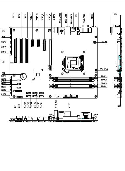
2.2 Location of Connectors and Jumpers
Component Side
Chapter 2 Quick Installation Guide 2 - 3
|
Industrial Motherboa rd |
|
|
I M B A - Q 7 7 |
|
|
|
|
|
||
|
|
|
|
|
|
|
|
|
|
|
|
Solder Side
Chapter 2 Quick Installation Guide 2 - 4

|
Industrial Motherboa rd |
|
|
I M B A - Q 7 7 |
|
|
|
|
|
||
|
|
|
|
|
|
|
|
|
|
|
|
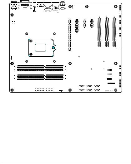
2.3 Mechanical Drawing
Component Side
Chapter 2 Quick Installation Guide 2 - 5

|
Industrial Motherboa rd |
|
|
I M B A - Q 7 7 |
|
|
|
|
|
||
|
|
|
|
|
|
|
|
|
|
|
|
Solder Side
Chapter 2 Quick Installation Guide 2 - 6

|
Industrial Motherboa rd |
|
|
I M B A - Q 7 7 |
|
|
|
|
|
||
|
|
|
|
|
|
|
|
|
|
|
|
2.4 List of Jumpers
The board has a number of jumpers that allow you to configure your system to suit your application.
The table below shows the function of each of the board's jumpers:
Label |
Function |
|
|
JP1 |
Clear CMOS |
|
|
JP3 |
AUTO POWER BUTTOM |
|
|
Chapter 2 Quick Installation Guide 2 - 7

|
Industrial Motherboa rd |
|
|
I M B A - Q 7 7 |
|
|
|
|
|
||
|
|
|
|
|
|
|
|
|
|
|
|
2.5 List of Connectors
The board has a number of connectors that allow you to configure your system to suit your application. The table below shows the function of each board's connectors:
Label |
Function |
|
|
|
|
FP1 |
Front Panel Connector 1 |
|
|
|
|
FP2 |
Front Panel Connector 2 |
|
|
|
|
CN5 |
VGA Port Pin Header |
|
|
|
|
COM2 |
RS-232 Pin Header |
|
|
|
|
COM3 |
RS-232 Pin Header |
|
|
|
|
COM4 |
RS-232 Pin Header |
|
|
|
|
COM5 |
RS-232 Pin Header |
|
|
|
|
COM6 |
RS-232 Pin Header |
|
|
|
|
DIO1 |
Digital I/O Pin Header |
|
|
|
|
LPT1 |
Parallel Port Pin Header |
|
|
|
|
USB1 |
USB Pin Header |
|
|
|
|
USB2 |
USB Pin Header |
|
|
|
|
USB3 |
USB Pin Header |
|
|
|
|
USB4 |
USB 3.0 Pin Header |
|
|
|
|
BT1 |
Battery |
|
|
|
|
IR1 |
IR Pin Header |
|
|
|
|
SATA1~SATA6 |
SATA Connector |
|
|
|
|
USB_LAN1 |
USB & 10/100/1000Base-T Ethernet Connector |
|
|
|
|
USB_LAN2 |
USB3.0 & 10/100/1000Base-T Ethernet |
|
Connector |
||
|
||
DIMM1 |
DDR3 DIMM Slot |
|
|
|
Chapter 2 Quick Installation Guide 2 - 8
|
|
Industrial Motherboa rd |
|
|
I M B A - Q 7 7 |
|
||
|
|
|
|
|
||||
|
|
|
|
|
|
|
|
|
|
|
|
|
|
|
|
|
|
|
|
|
|
|
|
|||
|
DIMM2 |
DDR3 DIMM Slot |
|
|
|
|||
|
|
|
|
|
|
|||
|
DIMM3 |
DDR3 DIMM Slot |
|
|
|
|||
|
|
|
|
|
|
|||
|
DIMM4 |
DDR3 DIMM Slot |
|
|
|
|||
|
|
|
|
|
|
|||
|
AUDIO1 |
AUDIO Connector |
|
|
|
|||
|
|
|
|
|
|
|||
|
CPU_FAN1 |
4-Pin Fan Connector |
|
|
|
|||
|
|
|
|
|
|
|||
|
CHASSIS_FAN1 |
4-Pin Fan Connector |
|
|
|
|||
|
|
|
|
|
|
|||
|
SYS_FAN1 |
4-Pin Fan Connector |
|
|
|
|||
|
|
|
|
|||||
|
CN2 |
DVI-D / COM1 RS232/422/485 |
||||||
|
|
|
|
|
|
|||
|
DP1 |
Display Port1 |
|
|
|
|||
|
|
|
|
|
|
|||
|
DP2/HDMI1 |
Display Port2 / HDMI |
|
|
|
|||
|
|
|
|
|
|
|||
|
KBMS1 |
PS/2 KB / MS |
|
|
|
|||
|
|
|
|
|
|
|||
|
ATX1 |
4 PIN ATX 12V |
|
|
|
|||
|
|
|
|
|
|
|||
|
ATX2 |
ATX Connector |
|
|
|
|||
|
|
|
|
|
|
|||
|
PCIE_1 |
PCI-E [x16] Connector |
|
|
|
|||
|
|
|
|
|
|
|||
|
PCIE_2 |
PCI-E [x4] Connector |
|
|
|
|||
|
|
|
|
|
|
|||
|
PCIE_3 |
PCI-E [x1] Connector |
|
|
|
|||
|
|
|
|
|
|
|||
|
PCIE_4 |
PCI-E [x1] Connector |
|
|
|
|||
|
|
|
|
|
|
|||
|
PCI1 |
PCI Connector |
|
|
|
|||
|
|
|
|
|
|
|||
|
PCI2 |
PCI Connector |
|
|
|
|||
|
|
|
|
|
|
|||
|
PCI3 |
PCI Connector |
|
|
|
|||
|
|
|
|
|
|
|
|
|
Chapter 2 Quick Installation Guide 2 - 9

|
Industrial Motherboa rd |
|
|
I M B A - Q 7 7 |
|
|
|
|
|
||
|
|
|
|
|
|
|
|
|
|
|
|
2.6 Setting Jumpers
You configure your card to match the needs of your application by setting jumpers. A jumper is the simplest kind of electric switch. It consists of two metal pins and a small metal clip (often protected by a plastic cover) that slides over the pins to connect them. To “close” a jumper you connect the pins with the clip.
To “open” a jumper you remove the clip. Sometimes a jumper will have three pins, labeled 1, 2 and 3. In this case you would connect either pins 1 and 2 or 2 and 3.
1 2 3
Open |
Closed |
Closed 2-3 |
A pair of needle-nose pliers may be helpful when working with jumpers.
If you have any doubts about the best hardware configuration for your application, contact your local distributor or sales representative before you make any change.
Generally, you simply need a standard cable to make most connections.
Chapter 2 Quick Installation Guide 2 - 10

Industrial Motherboa rd  I M B A - Q 7 7
2.7 Clear CMOS (JP1)
JP1 |
Function |
|
|
1-2 |
Protected (Default) |
|
|
2-3 |
Clear |
|
|
2.8 Auto Power Button(JP3)
JP3 |
Function |
|
|
1-2 |
Power ON by Button (Default) |
|
|
2-3 |
Auto Power ON |
|
|
2.9 Front Panel Connector (FP1)
Pin |
Signal |
Pin |
Signal |
|
|
|
|
1 |
Power On Button (+) |
2 |
Reset Switch (+) |
|
|
|
|
3 |
Power On Button (-) |
4 |
Reset Switch (-) |
|
|
|
|
5 |
HDD LED (+) |
6 |
Power LED (+) |
|
|
|
|
7 |
HDD LED (-) |
8 |
Power LED (-) |
|
|
|
|
2.10 Front Panel Connector (FP2)
Pin |
Signal |
Pin |
Signal |
|
|
|
|
1 |
External Speaker (+) |
2 |
Key Board Lock (+) |
|
|
|
|
3 |
NC |
4 |
GND |
|
|
|
|
5 |
Internal Buzzer (-) |
6 |
I2C Bus SMB Clock |
|
|
|
|
7 |
External Speaker (-) |
8 |
I2C Bus SMB Data |
Note: Internal Buzzer Enable: Close Pin 5,7
Chapter 2 Quick Installation Guide 2 - 11

Industrial Motherboa rd  I M B A - Q 7 7
2.11 RS-232 Serial Port Connector (COM2, 3, 4, 5, 6)
Pin |
Signal |
Pin |
Signal |
|
|
|
|
1 |
DCD |
2 |
RXD |
|
|
|
|
3 |
TXD |
4 |
DTR |
|
|
|
|
5 |
GND |
6 |
DSR |
|
|
|
|
7 |
RTS |
8 |
CTS |
|
|
|
|
9 |
RI |
|
|
|
|
|
|
2.12 IR Pin Header (IR1)
Pin |
Signal |
|
|
1 |
+5V |
|
|
2 |
NC |
|
|
3 |
RX |
|
|
4 |
GND |
|
|
5 |
TX |
|
|
2.13 Digital I/O Pin Header (DIO1)
Pin |
Signal |
Pin |
Signal |
|
|
|
|
1 |
DIO_30 |
2 |
DIO_31 |
|
|
|
|
3 |
DIO_32 |
4 |
DIO_33 |
|
|
|
|
5 |
DIO_34 |
6 |
DIO_35 |
|
|
|
|
7 |
DIO_36 |
8 |
DIO_37 |
|
|
|
|
9 |
+3.3V |
10 |
GND |
|
|
|
|
Chapter 2 Quick Installation Guide 2 - 12

Industrial Motherboa rd  I M B A - Q 7 7
2.14 VGA Port PIN Header (CN5)
Pin |
Signal |
Pin |
Signal |
|
|
|
|
1 |
VGA_RED_C |
2 |
V_VDO_5V |
|
|
|
|
3 |
VGA_GRE_C |
4 |
GND |
|
|
|
|
5 |
VGA_BLE_C |
6 |
NC |
|
|
|
|
7 |
NC |
8 |
VDO_MONID1_R |
|
|
|
|
9 |
GND |
10 |
V_HSYNC |
|
|
|
|
11 |
GND |
12 |
V_VSYNC |
|
|
|
|
13 |
GND |
14 |
VDO_MONID2_R |
|
|
|
|
15 |
GND |
16 |
NC |
|
|
|
|
2.15 USB2.0 Pin header (USB1~USB3)
Pin |
Signal |
Pin |
Signal |
|
|
|
|
1 |
+5V |
2 |
GND |
|
|
|
|
3 |
USBD- |
4 |
GND |
|
|
|
|
5 |
USBD+ |
6 |
USBD+ |
|
|
|
|
7 |
GND |
8 |
USBD- |
|
|
|
|
9 |
GND |
10 |
+5V |
|
|
|
|
2.16 USB3.0 Port PIN Header (USB4)
Pin |
Signal |
Pin |
Signal |
|
|
|
|
1 |
VCC |
20 |
NC |
|
|
|
|
2 |
USB3_RX1_DN_C |
19 |
VCC |
|
|
|
|
Chapter 2 Quick Installation Guide 2 - 13

|
|
|
|
Industrial Motherboa rd |
|
|
I M B A - Q 7 7 |
|
|
|
|
|
|
|
|
|
|
|
|
|
|||
|
|
|
|
|
|
|
|
|
|
|
|
|
|
|
|
|
|
|
|
|
|
|
|
|
|
|
|
|
|
|
|
||||
3 |
USB3_RX1_DP_C |
18 |
USB3_RX2_DN_C |
|
|
||||||
|
|
|
|
|
|
|
|
||||
4 |
GND |
17 |
USB3_RX2_DP_C |
|
|
||||||
|
|
|
|
|
|
|
|
||||
5 |
USB3_TX1_DN_C |
16 |
GND |
|
|
||||||
|
|
|
|
|
|
|
|
||||
6 |
USB3_TX1_DP_C |
15 |
USB3_TX2_DN_C |
|
|
||||||
|
|
|
|
|
|
|
|
||||
7 |
GND |
14 |
USB3_TX2_DP_C |
|
|
||||||
|
|
|
|
|
|
|
|
||||
8 |
USBP_0N_C |
13 |
GND |
|
|
||||||
|
|
|
|
|
|
|
|
||||
9 |
USBP_0P_C |
12 |
USBP_1N_C |
|
|
||||||
|
|
|
|
|
|
|
|
||||
10 |
NC |
11 |
USBP_1P_C |
|
|
||||||
|
|
|
|
|
|
||||||
2.17 Parallel Port Pin Header (LPT1) |
|
|
|
|
|||||||
|
|
|
|
|
|
|
|
|
|||
|
|
|
|
|
|
|
|
|
|||
|
|
|
Pin |
Signal |
Pin |
Signal |
|
|
|||
|
|
|
|
|
|
|
|||||
1 |
#STROBE |
2 |
#AFD |
|
|
||||||
|
|
|
|
|
|
|
|||||
3 |
DATA0 |
4 |
#ERROR |
|
|
||||||
|
|
|
|
|
|
|
|||||
5 |
DATA1 |
6 |
#INIT |
|
|
||||||
|
|
|
|
|
|
|
|||||
7 |
DATA2 |
8 |
#SLIN |
|
|
||||||
|
|
|
|
|
|
|
|||||
9 |
DATA3 |
10 |
GND |
|
|
||||||
|
|
|
|
|
|
|
|||||
11 |
DATA4 |
12 |
GND |
|
|
||||||
|
|
|
|
|
|
|
|||||
13 |
DATA5 |
14 |
GND |
|
|
||||||
|
|
|
|
|
|
|
|||||
15 |
DATA6 |
16 |
GND |
|
|
||||||
|
|
|
|
|
|
|
|||||
17 |
DATA7 |
18 |
GND |
|
|
||||||
|
|
|
|
|
|
|
|||||
19 |
#ACK |
20 |
GND |
|
|
||||||
|
|
|
|
|
|
|
|||||
21 |
BUSY |
22 |
GND |
|
|
||||||
|
|
|
|
|
|
|
|||||
23 |
PE |
24 |
GND |
|
|
||||||
|
|
|
|
|
|
|
|||||
25 |
SELECT |
26 |
GND |
|
|
||||||
|
|
|
|
|
|
|
|
|
|
|
|
Chapter 2 Quick Installation Guide 2 - 14

|
|
Industrial Motherboa rd |
|
|
I M B A - Q 7 7 |
|
|
|||||
|
|
|
|
|
|
|||||||
|
|
|
|
|
|
|
|
|
|
|
|
|
|
|
|
|
|
|
|
|
|
|
|
|
|
|
|
Below Table for China RoHS Requirements |
|
|
||||||||
|
|
|
|
|
|
|||||||
|
|
AAEON Main Board/ Daughter Board/ Backplane |
||||||||||
|
|
|
|
|
|
|
|
|
|
|
|
|
|
|
|
|
|
|
|
|
|
||||
|
|
|
|
|
|
|
|
|
|
|
||
|
|
|
|
|
|
|
|
|
||||
|
|
|
(Pb) |
(Hg) |
|
(Cd) |
(Cr(VI)) |
(PBB) |
|
(PBDE) |
||
|
|
|
|
|
|
|
|
|
|
|
|
|
|
|
|
|
|
|
|
|
|
|
|
|
|
|
|
|
× |
○ |
|
○ |
○ |
○ |
|
○ |
||
|
|
|
|
|
|
|
|
|
|
|
||
|
|
|
|
|
|
|
|
|
|
|
|
|
|
|
|
|
|
|
|
|
|
|
|
|
|
|
|
|
× |
○ |
|
○ |
○ |
○ |
|
○ |
||
|
|
|
|
|
|
|
|
|
|
|
||
|
|
|
|
|
|
|
|
|
|
|
|
|
|
|
|
|
|
|
|
|
|
|
|
|
|
|
|
|
|
|
|
|
|
|
|
|
|
|
|
|
|
|
|
|
|
|
|
|
|
|
|
|
|
|
|
|
|
|
|
|
|
|
|
|
|
|
|
|
|
|
|
|
|
|
|
|
|
|
|
|
|
|
|
|
|
|
|
|
|
|
|
|
|
|
|
|
|
|
|
|
|
|
|
|
|
|
|
|
|
|
|
|
|
|
|
|
O
SJ/T 11363-2006
X
SJ/T 11363-2006
Chapter 2 Quick Installation Guide 2 - 15

|
Industrial Motherboa rd |
|
|
I M B A - Q 7 7 |
|
|
|
|
|
||
|
|
|
|
|
|
|
|
|
|
|
|
Chapter
3
AMI
BIOS Setup
Chapter 3 AMI BIOS Setup 3-1

|
I n d ustrial Motherboa rd |
|
|
I M B A - Q 7 7 |
|
|
|
|
|
||
|
|
|
|
|
|
|
|
|
|
|
|
3.1 System Test and Iinitialization
These routines test and initialize board hardware. If the routines encounter an error during the tests, you will either hear a few short beeps or see an error message on the screen. There are two kinds of errors: fatal and non-fatal. The system can usually continue the boot up sequence with non-fatal errors.
System configuration verification
These routines check the current system configuration stored in the CMOS memory and BIOS NVRAM. If system configuration is not found or system configuration data error is detected, system will load optimized default and re-boot with this default system configuration automatically.
There are four situations in which you will need to setup system configuration:
1.You are starting your system for the first time
2.You have changed the hardware attached to your system
3.The system configuration is reset by Clear-CMOS jumper
4.The CMOS memory has lost power and the configuration information has been erased.
The IMBA-Q77 CMOS memory has an integral lithium battery backup for data retention. However, you will need to replace the complete unit when it finally runs down.
Chapter 3 AMI BIOS Setup 3-2

|
Industrial Motherboa rd |
|
|
I M B A - Q 7 7 |
|
|
|
|
|
||
|
|
|
|
|
|
|
|
|
|
|
|
3.2 AMI BIOS Setup
AMI BIOS ROM has a built-in Setup program that allows users to modify the basic system configuration. This type of information is stored in battery-backed CMOS RAM and BIOS NVRAM so that it retains the Setup information when the power is turned off. Entering Setup
Power on the computer and press <Del>or <F2> immediately. This will allow you to enter Setup.
Main
Set the date, use tab to switch between date elements.
Advanced
Enable disable boot option for legacy network devices.
Chipset
Host bridge parameters.
Boot
Enables/disable quiet boot option.
Security
Set setup administrator password.
Save & Exit
Exit system setup after saving the changes.
Chapter 3 AMI BIOS Setup 3-3
 Loading...