


 Loading...
Mini-ITX |
E M B - 6 9 0 8 T |
|
|
EMB-6908T
AMD AthlonTM 64/ Athlon 64 x2
(AM2 Socket) Processor,
Mini-ITX
Intel® 82573L, Dual Gigabit Ethernet
PCI-E x1 x 2 (optional)/
PCI/ Mini PCI/ HD 5.1CH Audio
EMB-6908T Manual Rev.A 1st Ed.
February 2009
Mini-ITX |
E M B - 6 9 0 8 T |
|
|
Copyright Notice
This document is copyrighted, 2009. All rights are reserved. The original manufacturer reserves the right to make improvements to the products described in this manual at any time without notice.
No part of this manual may be reproduced, copied, translated, or transmitted in any form or by any means without the prior written permission of the original manufacturer. Information provided in this manual is intended to be accurate and reliable. However, the original manufacturer assumes no responsibility for its use, or for any infringements upon the rights of third parties that may result from its use.
The material in this document is for product information only and is subject to change without notice. While reasonable efforts have been made in the preparation of this document to assure its accuracy, AAEON assumes no liabilities resulting from errors or omissions in this document, or from the use of the information contained herein.
AAEON reserves the right to make changes in the product design without notice to its users.
i
Mini-ITX |
E M B - 6 9 0 8 T |
|
|
Acknowledgments
All other products’ name or trademarks are properties of their respective owners.
CompactFlash™ is a trademark of the Compact Flash Association.
AMD, the AMD Arrow logo and combinations thereof are trademarks of Advanced Micro Devices, Inc.
Microsoft Windows® is a registered trademark of Microsoft Corp.
Please be notified that all other products’ name or trademarks not be mentioned above are properties of their respective owners.
ii
Mini-ITX |
E M B - 6 9 0 8 T |
|
|
Packing List
Before you begin installing your card, please make sure that the following materials have been shipped:
1 |
1701400453 |
IDE Cable |
1 |
1709070500 |
Serial ATA Cable |
1 |
1702150150 |
Serial ATA Power Cable |
1 |
9657666600 |
Jumper Cap |
1 |
M206908T00 |
I/O Shield, DVI + VGA Type |
1 |
Quick Installation Guide |
|
1 |
Utility DVD |
|
1 |
EMB-6908T |
|
If any of these items should be missing or damaged, please contact your distributor or sales representative immediately.
iii
Mini-ITX |
E M B - 6 9 0 8 T |
|
|
Contents
Chapter 1 General Information
1.1 |
Introduction ................................................................... |
1-2 |
1.2 |
Features........................................................................ |
1-3 |
1.3 |
Specifications................................................................ |
1-4 |
Chapter 2 Quick Installation Guide
2.1 |
Safety Precautions ...................................................... |
2-2 |
|
2.2 |
Location of Connectors and Jumpers ......................... |
2-3 |
|
2.3 |
Mechanical Drawing .................................................... |
2-5 |
|
2.4 |
List of Jumpers ............................................................ |
2-7 |
|
2.5 |
List of Connectors......................................................... |
2-8 |
|
2.6 |
Setting Jumpers ........................................................ |
2-10 |
|
2.7 |
COM2 Ring/ +5V/+12V Selection (JP2)...................... |
2-11 |
|
2.8 |
LVDS-LCD Voltage Selection (JP3) ........................... |
2-11 |
|
2.9 |
LCD INVERTER Voltage Selection (JP3)................... |
2-11 |
|
2.10 |
Simulate AT Selection (JP4) ................................... |
2-11 |
|
2.11 |
Clear CMOS (JP5).................................................... |
2-11 |
|
2.12 |
CRT Connector (CN1) .............................................. |
2-11 |
|
2.13COM1/ COM2 RS-232 Serial Port Connector (CN2) 2-12
2.14Audio Connector Line-IN/ Line-OUT/ Mic-IN (CN3).. 2-13
2.15 |
PS2 Keyboard/ Mouse Connector (CN4) ................. |
2-13 |
2.16 |
Audio 5.1 Channel / SPDIF Connector (CN5) .......... |
2-13 |
2.17 |
3rd USB Connector/ 10/100/1000Base-TX Ethernet |
|
Connector (2) (CN6) ........................................................ |
2-14 |
|
iv
|
Mini-ITX |
|
E M B - 6 9 0 8 T |
|
|
|
|
|
|
|
|
2.18 |
1st USB Connector/ 10/100/1000Base-TX Ethernet |
|
|
||
Connector (1) (CN7) ......................................................... |
|
2-14 |
|||
2.19 |
Audio Speak Out Connector (CN9) .......................... |
2-15 |
|||
2.20 |
Internal Keyboard Connector (CN10) ....................... |
2-15 |
|||
2.21 |
CD-IN Connector (CN11) ........................................ |
|
2-15 |
||
2.22 |
LVDS-LCD Connector (CN12).................................. |
|
2-15 |
||
2.23 |
LCD Inverter Connector (CN13) ............................... |
2-16 |
|||
2.24 |
Internal Mouse Connector (CN14)............................ |
2-16 |
|||
2.25 |
Front Panel Connector (CN15)................................. |
|
2-16 |
||
2.26 |
Fan 1 Connector (CN16) .......................................... |
|
2-17 |
||
2.27 |
3rd Serial ATA Connector (CN17) ............................ |
2-17 |
|||
2.28 |
4th Serial ATA Connector (CN20) ............................ |
2-17 |
|||
2.29 |
2nd Serial ATA Connector (CN21) ........................... |
2-18 |
|||
2.30 |
External RTC Connector (CN22).............................. |
2-18 |
|||
2.31 |
ATX Power Connector (CN23) ................................. |
|
2-18 |
||
2.32 |
1st Serial ATA Connector (CN25)............................. |
2-19 |
|||
2.33 |
PCI-Express Connector (CN26) ............................... |
2-19 |
|||
2.34 |
5th USB Connector (CN27) ...................................... |
|
2-20 |
||
2.35 |
4th USB Connector (CN28) ...................................... |
|
2-21 |
||
2.36 |
2nd USB Connector (CN29) ..................................... |
|
2-21 |
||
2.37 |
COM6 RS-232 Serial Port Connector (CN30) .......... |
2-21 |
|||
2.38 |
COM5 RS-232 Serial Port Connector (CN31) .......... |
2-22 |
|||
2.39 |
COM3 RS-232 Serial Port Connector (CN32) .......... |
2-22 |
|||
2.40 |
COM4 RS-232 Serial Port Connector (CN33) .......... |
2-22 |
|||
2.41 |
IrDA Connector (CN34) ............................................ |
|
2-22 |
||
v
|
|
Mini-ITX |
|
E M B - 6 9 0 8 T |
|
|
|
|
|
|
|
|
|
||
|
2.42 Fan2 Connector (CN35) ........................................... |
|
2-23 |
||||
|
2.43 LPT Port Connector (CN36) ..................................... |
|
2-23 |
||||
|
2.44 Digital I/O Connector (CN37, CN38)......................... |
2-24 |
|||||
Chapter 3 Award BIOS Setup |
|
|
|
||||
|
3.1 System Test and Initialization....................................... |
|
3-2 |
||||
|
3.2 Award BIOS Setup........................................................ |
|
3-3 |
||||
Chapter 4 |
Driver Installation |
|
|
|
|||
|
4.1 Installation..................................................................... |
|
4-3 |
||||
Appendix A Programming The Watchdog Timer |
|
|
|||||
|
A.1 |
Programming................................................................ |
|
A-2 |
|||
|
A.2 |
IT8712 Watchdog Timer Initial Program ...................... |
A-6 |
||||
Appendix B |
I/O Information |
|
|
|
|||
|
B.1 |
I/O Address Map........................................................... |
|
B-2 |
|||
|
B.2 Memory Address Map .................................................. |
|
B-4 |
||||
|
B.3 |
IRQ Mapping Chart....................................................... |
|
B-5 |
|||
|
B.4 |
DMA Channel Assignments ......................................... |
|
B-5 |
|||
Appendix C |
Mating Connector |
|
|
|
|||
|
C.1 List of Mating Connectors and Cables ........................ |
C-2 |
|||||
vi

Mini-ITX |
E M B - 6 9 0 8 T |
|
|
Chapter
1
General
Information
Chapter 1 General Information 1- 1

Mini-ITX |
E M B - 6 9 0 8 T |
|
|
1.1 Introduction
The EMB-6908T adopts the latest AMD Athlon (AM2 Socket) processor and AMD M690T+ SB600 chipset for a lower power consumption and higher performance solution. EMB-6908T utilizes two DDRII 240-pin DIMM system memory that supports ECC dual-channel DDRII 533/667 up to 4GB. It is the latest embedded motherboard designed to cope with increasingly heavily worked-loaded embedded systems, such as digital signage, POS (Point of Sales) machines, banking machine, medical instruments, gaming machine, and etc.
The EMB-6908T accommodates two optional PCI-Express x1 slots, one PCI slot and one Mini PCI slot for a flexible expansion. Moreover, it supports various storages including one EIDE, and four SATA ports. The I/O expansion of EMB-6908T features six COM ports, 10 USB2.0, one Parallel port, one DVI-I port, two Gigabit Ethernet ports, and HD 5.1CH Audio that are enable for expanding system functions.
The EMB-6908T provides numerous features for the embedded systems and will be the best solution for your complicated applications.
Chapter 1 General Information 1-2

Mini-ITX |
E M B - 6 9 0 8 T |
|
|
1.2 Features
AMD Athlon 64/ Athlon 64 x2 (AM2 Socket) Processors AMD 690E + SB600
ECC Dual-channel DDRII 533/667 Memory, Up To 4GB Gigabit Ethernet x 2
CRT, Up to 24-bit Dual-channel LVDS LCD, DVI HD 5.1CH Audio
EIDE x 1, SATA x 4
COM x 6, USB2.0 x 10, 16-bit Digital I/O
PCI x 1, Mini PCI x 1, PCI-E [x1] x 2 in PCI-E [x4] Slot (Through Riser Card)
TPM 1.2 (Optional) ATX
Chapter 1 General Information 1-3
Mini-ITX |
E M B - 6 9 0 8 T |
|
|
1.3 Specifications
System |
|
|
Processor |
AMD AthlonTM 64/ AthlonTM |
|
|
64 x2 (AM2 Socket) |
|
|
Processors (Low Power |
|
|
Version Only: Athlon 2000+, |
|
|
Athlon 2600+, Athlon 3400e) |
|
System Memory |
240-pin DDRII DIMM Socket |
|
|
x 2, total up to 4GB (DDRII |
|
|
533/667), supports |
ECC |
|
function |
|
Chipset |
AMD M690E + SB600 |
|
I/O Chipset |
ITE IT8712F-A/IX-L |
|
Ethernet |
Intel® 82573L, |
|
|
10/100/1000Base-TX, |
|
|
RJ-45 x 2 |
|
BIOS |
Award |
|
Watchdog Timer |
ITE IT8712F-A/IX-L |
|
Wake on LAN |
Yes |
|
H/W Status Monitoring |
Supports power supply |
|
|
voltages, fan speed and |
|
|
temperature monitoring |
|
Power Requirement |
ATX |
|
Power Consumption |
3000+ 1.8GHz, DDRII |
533 |
Chapter 1 General Information 1-4

Mini-ITX |
E M B - 6 9 0 8 T |
|
|
(Typical) |
1GB; 3.19A @ +12V, 2.78A |
|
@ +5V |
Board Size |
6.7”(L) x 6.7”(W) (170 mm x |
|
170 mm) |
Gross Weight |
1.32lb (0.6kg) |
Operating Temperature |
32˚F~ 140˚F (0˚C ~ 60˚C) |
Storage Temperature |
-40˚F~ 176˚F (-40˚C ~ 80˚C) |
Operating Humidity |
0%~90% relative humidity, |
|
non-condensing |
MTBF (Hours) |
90,000 |
Display: Supports LCD/CRT, LCD/DVI, CRT/DVI
Simultaneous/Dual View Display
Chipset |
AMD M690T integrated |
Memory |
Shared system memory up to |
|
256MB |
Resolution |
CRT: up to 2560 x 1440 @ |
|
75Hz; |
|
LCD: up to 2048 x 1536 |
|
(QXGA); |
|
Single Link DVI: up to 1600 x |
|
1200 @ 60Hz with pixel clock |
|
162MHz; up to 1920 x 1200 @ |
|
60Hz with pixel clock 154MHz; |
|
Dual-Link DVI: up to 2560 x |
Chapter 1 General Information 1-5

Mini-ITX |
E M B - 6 9 0 8 T |
|
|
|
1600 @ 60Hz with pixel clock |
|
268MHz |
LCD Interface |
Up to 24-bit dual-channel LVDS |
Side Port |
1 x 16-bit memory interface, |
|
supports up to 128MB DDRII |
|
800 memory |
|
(TF-EMB-6908T-A12-01 only) |
I/O
Storage |
EIDE x 1 (one device), SATA x 4 |
Serial Port |
RS-232 x 5, RS-232/422/485 x 1 |
Parallel Port |
SPP/ EPP/ ECP mode |
USB |
USB2.0 x 10 |
PS/2 Port |
Keyboard x 1, Mouse x 1 |
Digital I/O |
Supports 16-bit (Programmable) |
IrDA |
One IrDA Tx/Rx header |
Audio |
5.1CH audio |
Chapter 1 General Information 1-6
Mini-ITX |
E M B - 6 9 0 8 T |
|
|
Chapter
2
Quick
Installation
Guide
Notice:
The Quick Installation Guide is derived from Chapter 2 of user manual. For other chapters and further installation instructions, please refer to the user manual CD-ROM that came with the product.
Part No. 2007690810 Printed in Taiwan February 2009
Chapter 2 Quick Installation Guide 2 - 1
Mini-ITX |
E M B - 6 9 0 8 T |
|
|
2.1 Safety Precautions
Always completely disconnect the power cord from your board whenever you are working on it. Do not make connections while the power is on, because a sudden rush of power can damage sensitive electronic components.
Always ground yourself to remove any static charge before touching the board. Modern electronic devices are very sensitive to static electric charges. Use a grounding wrist strap at all times. Place all electronic components on a static-dissipative surface or in a static-shielded bag when they are not in the chassis
Chapter 2 Quick Installation Guide 2 - 2
Mini-ITX |
E M B - 6 9 0 8 T |
|
|
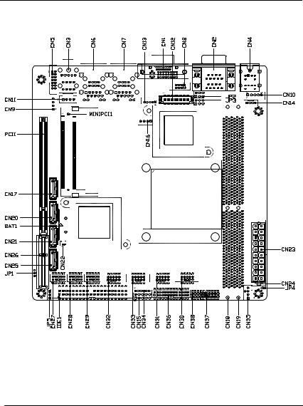
2.2 Location of Connectors and Jumpers
Locating Connectors and Jumpers (Component Side)
Chapter 2 Quick Installation Guide 2 - 3

Mini-ITX |
E M B - 6 9 0 8 T |
|
|
Locating Connectors and Jumpers (Solder Side)
Chapter 2 Quick Installation Guide 2 - 4

Mini-ITX |
E M B - 6 9 0 8 T |
|
|
2.3 Mechanical Drawing
Component Side
Chapter 2 Quick Installation Guide 2 - 5

Mini-ITX |
E M B - 6 9 0 8 T |
|
|
Solder Side
Chapter 2 Quick Installation Guide 2 - 6

Mini-ITX |
E M B - 6 9 0 8 T |
|
|
2.4 List of Jumpers
The board has a number of jumpers that allow you to configure your system to suit your application.
The table below shows the function of each of the board's jumpers:
Label |
Function |
|
JP2 |
COM2 Ring/+5V/+12V Selection |
|
JP3 |
LVDS-LCD Voltage/ LCD INVERTER Voltage |
|
Selection |
||
|
||
JP4 |
Simulate AT Selection |
|
JP5 |
Clear CMOS |
Chapter 2 Quick Installation Guide 2 - 7
Loading...