

Page 1

Network Appliance
FWS- 8 1 6 B
FWS-816B
1U Rackmount
Network Appliance Platform
1 3.5” Disk Drive bay
8 LAN Ports
2 Type A USB Ports
FWS-816 Manual Rev. B 2nd Ed.
April 28, 2014
Page 2

Network Appliance
FWS- 8 1 6 B
Copyright Notice
This document is copyrighted, 2014. All rights are reserved. The
original manufacturer reserves the right to make improvements to the
products described in this manual at any time without notice.
No part of this manual may be reproduced, copied, translated, or
transmitted in any form or by any means without the prior written
permission of the original manufacturer. Information provided in this
manual is intended to be accurate and reliable. However, the original
manufacturer assumes no responsibility for its use, or for any infringements upon the rights of third parties that may result from its
use.
The material in this document is for product information only and is
subject to change without notice. While reasonable efforts have been
made in the preparation of this document to assure its accuracy,
AAEON assumes no liabilities resulting from errors or omissions in
this document, or from the use of the information contained herein.
AAEON reserves the right to make changes in the product design
without notice to its users.
i
Page 3

Network Appliance
FWS- 8 1 6 B
Acknowledgments
All other products’ name or trademarks are properties of their
respective owners.
Award is a trademark of Award Software International, Inc.
CompactFlash™ is a trademark of the Compact Flash
Association.
Intel®, Pentium® M, and Core 2 Duo are trademarks of Intel®
Corporation.
Microsoft Windows® is a registered trademark of Microsoft Corp.
ISoundBlaster is a trademark of Creative Labs, Inc.
All other product names or trademarks are properties of their
respective owners.
ii
Page 4

Network Appliance
FWS- 8 1 6 B
Caution
There is a danger of explosion if the battery is incorrectly replaced.
Replace only with the same or equivalent type recommended by the
manufacturer. Dispose of used batteries according to the
manufacturer’s instructions and your local government’s recycling or
disposal directives.
Attention:
Il y a un risque d’explosion si la batterie est remplacée de façon incorrecte.
Ne la remplacer qu’avec le même modèle ou équivalent recommandé par le
constructeur. Recycler les batteries usées en accord avec les instructions du
fabricant et les directives gouvernementales de recyclage.
iii
Page 5

Network Appliance
FWS- 8 1 6 B
Packing List
Before you begin installing your card, please make sure that the
following materials have been shipped:
1 FWS-816B
1 Quick Installation Guide
1 CD-ROM for manual (in PDF format) and drivers
1 Heatpipe Module
1 Serial ATA Cable
1 Hard Disk Drive Power Cable
2 Ear Brackets
Screw Accessories
If any of these items should be missing or damaged, please
contact your distributor or sales representative immediately.
Note:
PS2 keyboard/mouse cable and VGA Cable are optional
accessories, please purchase those cables according to the
following item numbers.
1701160302 VGA Cable
1700060150 PS2 KB/MS Cable
iv
Page 6

Network Appliance
FWS- 8 1 6 B
Contents
Chapter 1 General Information
1.1 Introduction ................................................................ 1-2
1.2 Features .................................................................... 1-3
1.3 Specifications ............................................................ 1-4
1.4 General System Information ..................................... 1-7
Chapter 2 Quick Installation Guide
2.1 Safety Precautions .................................................... 2-2
2.2 Location of Connectors ............................................. 2-3
2.3 Mechanical Drawing .................................................. 2-4
2.4 List of Jumpers .......................................................... 2-5
2.5 List of Connectors ..................................................... 2-6
2.6 Setting Jumpers ........................................................ 2-7
2.7 Clear CMOS (JP1) .................................................... 2-8
2.8 Front Panel Connector (FP1) .................................... 2-8
2.9 Front Panel Connector (FP2) .................................... 2-8
2.10 USB Connector (USB1) .......................................... 2-9
2.11 USB Pin Header (CN4, CN5) .................................. 2-9
2.12 RS-232 Serial Port Connector (COM1/2) ................ 2-9
2.13 Power Connector (ATX2) ........................................ 2-10
2.14 VGA Connector (CN1)............................................. 2-10
2.15 FAN Connector (CPUFAN1) ................................... 2-11
2.16 FAN Connector (FAN1, FAN2, FAN3) .................... 2-11
v
Page 7

Network Appliance
FWS- 8 1 6 B
2.17 RJ-45 Phone Jack Connector (LAN1-8).................. 2-11
2.18 PS2 Keyboard/ Mouse Connector (CN7) ................ 2-12
2.19 SATA Power Connector (PWR1) ............................ 2-12
2.20 LCM & Key Pad Control Connector (LCMA1) ......... 2-12
2.21 Power Connector for PCI-X Riser (CN8)................. 2-13
2.22 Removing the Cover................................................ 2-14
2.23 Installing the CPU and the Heatpipe ....................... 2-15
2.24 Installing the Hard Disk Drive .................................. 2-23
2.25 Installing the Add-on Card ....................................... 2-26
Chapter 3 Award BIOS Setup
3.1 System Test and Initialization ................................... 3-2
3.2 Award BIOS Setup .................................................... 3-3
Chapter 4 Driver Installation
4.1 Installation ................................................................. 4-3
Appendix A Programming the Watchdog Timer
A.1 Programming ......................................................... A-2
A.2 W83627EHG Watchdog Timer Initial Program ...... A-6
Appendix B I/O Information
B.1 I/O Address Map .................................................... B-2
B.2 Memory Address Map ............................................ B-3
B.3 IRQ Mapping Chart ................................................ B-4
B.4 DMA Channel Assignments ................................... B-4
vi
Page 8

Network Appliance
FWS- 8 1 6 B
Appendix C Standard Firewall Platform Setting
C.1 Standard Firewall Platform Setting ....................... C-2
C.2 Status LED Sample Code ..................................... C-3
C.3 LAN Bypass Mode Sample Code ......................... C-6
C.4 LCM Sample Code ............................................... C-8
C.5 Console Redirection ........................................... C-14
vii
Page 9

Network Appliance FWS-816B
Information
Chapter
1
General
Chapter 1 General Information 1- 1
Page 10

Network Appliance FWS-816B
1.1 Introduction
FWS-816 Rev.B adopts the Core 2 Duo LGA 775 Processor, up to
2.66GHz with 533/800/1066 Front Side Bus. Moreover, the
chipset is equipped with Intel
®
945G and Intel® 82801FB (ICH7R).
The system memory features 2x240-pin DDRII 667 SDRAM DIMM
socket total up to 4GB and supports dual channel. It deploys eight
LAN ports that consist of six PCIe Gigabit Ethernet LAN ports with
two ports bypass function and two 10/100Base-TX LAN ports.
FWS-816’s condensed appearance features 1U form factor that fits
nicely into a space limited environment.
This compact FWS-816B is equipped with one Ultra ATA, two
SATA II and CompactFlash
TM
Type II connector with ATA mode.
In addition, it offers flexible expansion with network products and
features one PCI expansion slot, one Mini PCI slot, two USB2.0
ports and one RS-232 console port. The console port deploys
console re-direction that increases the network security via
remote control. Moreover, there is a front panel support LCM
with keypad control that allows for easy access and operation.
All of these designs provide for a more user-friendly solution.
Chapter 1 General Information 1- 2
Page 11

Network Appliance FWS-816B
1.2 Features
1U eight LAN ports network appliance platform
Intel
2x240-pin dual channel DDRII 667 SDRAM DIMM
®
Core 2 Duo CPU up to 2.66GHz (Dual Core up
to 3.6GHz) (Tc =70.8
o
@ 115W)
support up to 4GB (DIMM Height under 31mm)
Six 10/100/1000Base-TX ports (2 ports bypass
function) & two 10/100 Ethernet ports
One Ultra ATA-100 port & two SATA II ports
CompactFlash Type-II connector & DOM up to 2GB
(DOM Height under 29mm)
250W power with auto range input
Six USB2.0 ports (4 Pin Headers)
Parallel LCM with keypad & two USB2.0 ports & one
RS-232 console (front panel) port
One internal 3.5" disk drive bay
PCI-E[x1]/ PCI-X/ PCI Expansion Slot (Optional)
Chapter 1 General Information 1- 3
Page 12

Network Appliance FWS-816B
1.3 Specifications
System
Construction:
CPU
Memory
LAN
BIOS
IDE
SA TA Interface
Solid Storage Disk
1U 8-port firewall heavy-duty steel system
®
Intel
Core 2 Duo LGA775 up to 2.66GHz
(FSB 400/533/800/1066, Dual Core up to
3.6GHz ) (Tc =70.8
o
@ 115W)
2 x 240-pin DDRII 667 DIMM Socket, total
up to 4GB, Support Dual Channel
6 x PCI-E【x1】dual 10/100/1000Mb LAN
(with 2-port bypass LAN3 & LAN4 ),
2x PCI 10/100Mb, RJ-45 X8
Award Plug & Play FWH BIOS – 4Mb
ROM
AT A-100 x 1 channel (Supports CD-ROM
ATAPI devices)
SATA II x 2
Supports CFD Type II connector(ATA
mode)
Expansion Interface
Watchdog Timer
RTC
Storage
Chapter 1 General Information 1- 4
Mini PCI Type III Socket
1~255 steps, can be set with software on
Super I/O
Internal RTC
Internal:One 3.5" Hard Disk Drive Bay
Page 13

Network Appliance FWS-816B
System Fan
Three 4cm Ball Bearing Fans
Color
LCM
Power Supply
Dimensions
Net Weight
Display
VGA Controller
I/O
Serial Port
Keyboard & Mouse
Universal Serial Bus
Front I/O Panel
Blue and Red
2 x16 characters with 4 keypad control
ATX 250W, auto range
16.93” (W) x 14.96” (D) x 1.73”(H)
(430mm x 380mm x 44mm) —Chassis
9.84” (W) x 11.02” (D) (250mm x
280mm) —Board
17.6 lb (8 kg)
Integrated VGA on Intel 945G, pin header
connector
Two COM ports: (Internal Pin Header x
1)
COM 1: RS-232
COM 2: RS-232 (Pin Header)
Reserve pin header
Two TYPE-A Connectors on front panel
One Power LED
One Bypass LED
One Status LED
One HDD Active LED
Eight LAN LEDs
Chapter 1 General Information 1- 5
Page 14

Network Appliance FWS-816B
Two USB Ports
Rear I/O panel
Environmental
Operating Temp.
Storage Temp.
Operating humidity:
Storage humidity:
Vibration
Shock
Eight LAN Ports
One DB-9 connector
One LCM Display
One Reset Button
One PCI-E[x1]/ PCI-X/ PCI expansion
slot (Optional)
32°F ~ 104°F (0°C ~ 40°C)
-4°F ~ 140°F (-20°C ~ 60°C)
10 ~ 80%
10 ~ 80% @ 40°C, non-condensing
0.5G / 5 ~ 500Hz / operation (3.5” Hard
Disk Drive)
1.5G / 5 ~ 500Hz / non operation
10G peak acceleration (11 m sec.
Chapter 1 General Information 1- 6
duration), operation
20G peak acceleration (11 m sec.
duration), non operation
Page 15
Network Appliance FWS-816B
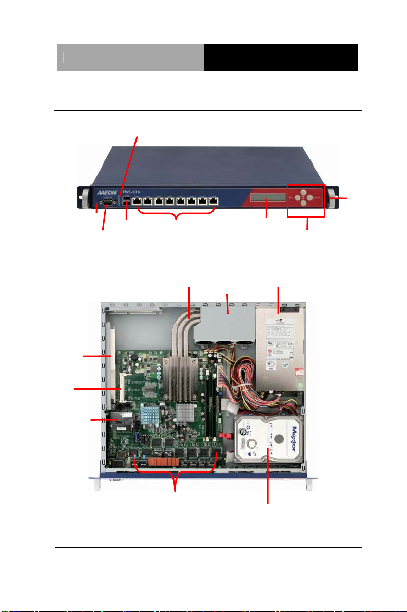
1.4 General System Information
Front Panel
Reset
Console Port
Inside
PCI Riser
Mini PCI
CompactFlash
LEDs for Bypass, HDD Active, Status, Power
2 USB Ports
8 LAN Ports
CPU Heatpipe
Heatsink & Fan
Handle
LCM Display
Keypad Control
1U Power Supply
8 LAN Chipsets
3.5” Hard Disk Drive (Optional)
Chapter 1 General Information 1- 7
Page 16

Network Appliance FWS-816B
d
f
r
r
e
p
Chapter
FWS-816B
Installation
2
Quick
Guide
Chapter 2 Quick Installation Guide 2-1
The Quick Installation Guide is derive
rom Chapter 2 of the user manual. Fo
other chapters and further installation
instructions, please refer to the use
manual CD-ROM that came with th
roduct.
Part No. 2001816020 Printed in Taiwan Nov. 2007
Notice:
Page 17
Network Appliance FWS-816B
2.1 Safety Precautions
The installation is intended for technically qualified personnel who
have experience installing and configuring system boards.
The equipment can be installed in a restricted access location (RAL)
only.
A restricted access location is a site location for equipment where
the following criteria apply:
01. Access can only be gained by service persons or by users who
have been trained on the restrictions and the precautions for this
specific site.
02. Access is by means of at least one of the following, special tool,
lock and key, or other means of security, and is controlled by the
authority responsible for the location.
Safety Precautions:
Always completely disconnect the power cord
from your board whenever you are working on
it. Do not make connections while the power is
on, because a sudden rush of power can
damage sensitive electronic components.
Always ground yourself to remove any static
charge before touching the board. Modern
electronic devices are very sensitive to static
electric charges. Use a grounding wrist strap at
all times. Place all electronic components on a
static-dissipative surface or in a static-shielded
bag when they are not in the chassis
Chapter 2 Quick Installation Guide 2-2
Page 18
Network Appliance FWS-816B
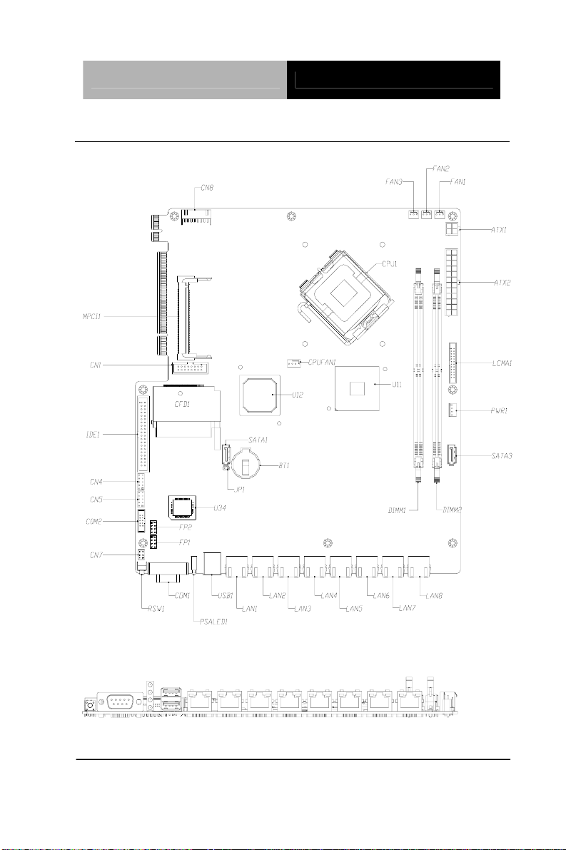
2.2 Location of Connectors
Chapter 2 Quick Installation Guide 2-3
Page 19
Network Appliance FWS-816B
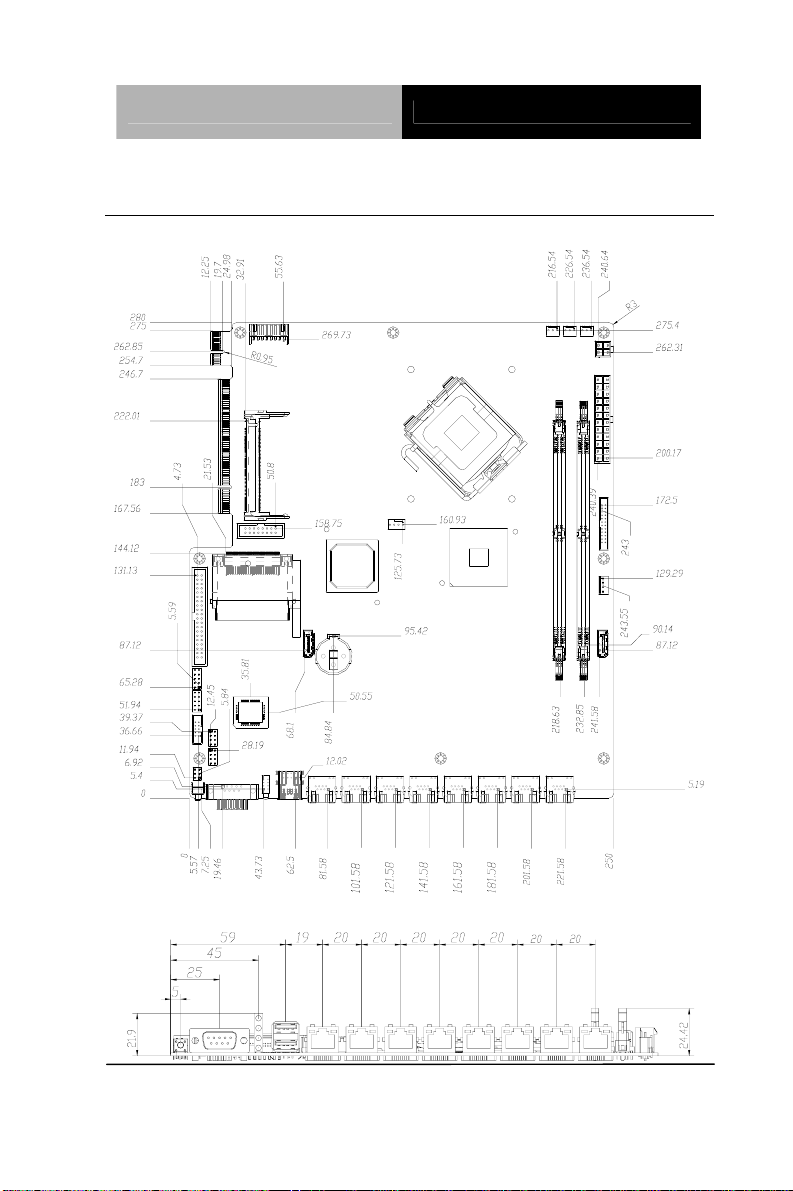
2.3 Mechanical Drawing
Chapter 2 Quick Installation Guide 2-4
Unit: mm
Page 20

Network Appliance FWS-816B
2.4 List of Jumpers
The board has a number of jumpers that allow you to configure your
system to suit your application.
The table below shows the function of each of the board's jumpers:
Label Function
JP1 Clear CMOS
FP1 Front Panel Connector 1
FP2 Front Panel Connector 2
Chapter 2 Quick Installation Guide 2-5
Page 21

Network Appliance FWS-816B
2.5 List of Connectors
The board has a number of connectors that allow you to configure
your system to suit your application. The table below shows the
function of each board's connectors:
Label Function
ATX2 ATX Power Connector
ATX1 ATX Power_12V Connector
SATA1 & 3 Serial ATA Connector
CN1 VGA Display PIN HEADER
IDE1 IDE Connector
USB1 USB Connector
CN4、5
COM2 RS-232 Serial Port PIN HEADER
COM1 RS-232 Serial Port Connector
DIMM1~2 DIMM Slot
FAN1~3 Fan Connector
CPUFAN1 Fan Connector
LAN1~8 RJ-45 PHONEJACK Connector
CN7 PS2 Keyboard/Mouse Connector
PWR1 SATA POWER Connector
CFD1 Compact Flash Slot
MPCI1 Mini PCI Slot
LCMA1 LCM & Key Pad Control PIN HEADER
CN8 Power Connector for PCI-X Riser
Note: DIMM height limitation is 31mm; DOM height limitation is 29mm.
Chapter 2 Quick Installation Guide 2-6
USB PIN HEADER
Page 22
Network Appliance FWS-816B
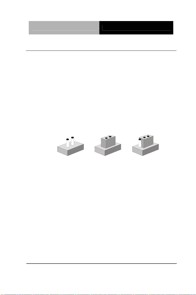
2.6 Setting Jumpers
You configure your card to match the needs of your application by
setting jumpers. A jumper is the simplest kind of electric switch. It
consists of two metal pins and a small metal clip (often protected by
a plastic cover) that slides over the pins to connect them. To “close”
a jumper you connect the pins with the clip.
To “open” a jumper you remove the clip. Sometimes a jumper will
have three pins, labeled 1, 2 and 3. In this case you would connect
either pins 1 and 2 or 2 and 3.
3
2
1
Open Closed Closed 2-3
A pair of needle-nose pliers may be helpful when working with
jumpers.
If you have any doubts about the best hardware configuration for
your application, contact your local distributor or sales
representative before you make any change.
Generally, you simply need a standard cable to make most
connections.
Chapter 2 Quick Installation Guide 2-7
Page 23

Network Appliance FWS-816B
2.7 Clear CMOS (JP1)
JP1 Function
1-2 Clear
Open Protected (Default)
2.8 Front Panel Connector (FP1)
Pin Signal Pin Signal
1 Power On Button (+) 2
3 Power On Button (-) 4
5
IDE LED (+)
7
IDE LED (-)
Reset Switch (+)
Reset Switch (-)
6
Power LED (+)
8
Power LED (-)
2.9 Front Panel Connector (FP2)
Pin Signal Pin Signal
1
External Speaker (+)
3
NC
5
Internal Buzzer (-)
7
External Speaker (-)
Note: Internal Buzzer enable: Close Pin 5,7
2
NC
4
NC
6
I2C Bus SMB Clock
8
I2C Bus SMB Data
Chapter 2 Quick Installation Guide 2-8
Page 24

Network Appliance FWS-816B
2.10 USB Connector (USB1)
Pin Signal Pin Signal
1
3
5
7
GND
XUSBD4GND
XUSBD5-
2
4
6
8
XUSBD4+
+5V
XUSBD5+
+5V
Note: When activating the COM port LL5 test, please “Disable” the USB
keyboard and mouse in BIOS setting.
2.11 USB Pin Header (CN4, CN5)
Pin Signal Pin Signal
1
+5V
3
USBD-
5
USBD+
7
GND
9
GND
2
4
6
8
10
GND
GND
USBD+
USBD+5V
2.12 RS-232 Serial Port Connector (COM1/2)
Pin Signal Pin Signal
1
DCD
3
TXD
5
GND
2
RXD
4
DTR
6
DSR
Chapter 2 Quick Installation Guide 2-9
Page 25

Network Appliance FWS-816B
7
RTS
8
CTS
9
RI
2.13 Power Connector (ATX2)
Pin Signal Pin Signal
1 +3.3V 2
3 GND 4
5 GND 6
7 GND 8
9 +5VSB 10
11 +12V 12
13 +3.3V 14
15 GND 16
17 GND 18
19 GND 20
21 +5V 22
+3.3V
+5V
+5V
PWROK
+12V
+3.3V
-12V
PS_ON
GND
NC
+5V
23 +5V 24
GND
2.14 VGA Connector (CN1)
Pin Signal Pin Signal
1 VGA R 2
3 VGA G 4
Chapter 2 Quick Installation Guide 2-10
VGA VCC
GND
Page 26

Network Appliance FWS-816B
5 VGA B 6
NC
7 NC 8
9 GND 10
11 GND 12
13 GND 14
15 GND 16
VGA DATA
VGA HS
VGA VS
VGA CLK
NC
2.15 FAN Connector (CPUFAN1)
Pin Signal Pin Signal
1 GND 2
3 SENCE 4
+12V
CTRL
2.16 FAN Connector (FAN1, FAN2, FAN3)
Pin Signal Pin Signal
1 GND 2
3 SENCE
+12V
2.17 RJ-45 Phone Jack Connector (LAN1~8)
Pin Signal Pin Signal
1 TX+ 2
3 RX+ 4
5 T45 6
TX-
RX-
T45
Chapter 2 Quick Installation Guide 2-11
Page 27

Network Appliance FWS-816B
7 T78 8
T78
9 BLINK100- 10
11 BACT 12
13 GND 14
BLINK1G-
+3.3V
GND
2.18 PS2 Keyboard/ Mouse Connector (CN7)
Pin Signal
1 KB_DATA
2 KB_CLK
3 GND
4 +5V
5 MS_DATA
6 MS_CLK-
2.19 SATA Power Connector (PWR1)
Pin Signal Pin Signal
1 +12V 2
GND
3 GND 4
+5V
2.20 LCM & Key Pad Control Connector (LCMA1)
Pin Signal Pin Signal
1 POWER 2
3 LSLIN- 4
Chapter 2 Quick Installation Guide 2-12
GND
VEE
Page 28

Network Appliance FWS-816B
5 LAFD- 6
LINIT7 LPD1 8
9 LPD3 10
11 LPD5 12
13 LPD7 14
15 LCD- 16
17 UP 18
19 LEFT 20
21 RESET 22
23 NC 24
LPD0
LPD2
LPD4
LPD6
VCC
RIGHT
DOWN
NC
NC
2.21 Power Connector for PCI-X Riser (CN8)
Pin Signal Pin Signal
1 GND 2
3 +3.3V 4
5 -12V 6
+3.3V
+3.3V
+5V
7 +5V 8
GND
Chapter 2 Quick Installation Guide 2-13
Page 29

Network Appliance FWS-816B
2.22 Removing the Cover
Before you install drives or plug-in cards into the FWS-816B, please
switch the unit off and remove the power cord first.
Step 1: Unscrew the upper lid
Back Side
Right Side
Step 2: Isolate the upper lid from the chassis
Left Side
Chapter 2 Quick Installation Guide 2-14
Page 30

Network Appliance FWS-816B
2.23 Installing the CPU and the Heatpipe
Step 1: Get the white tape from the interstice
Step 2: Pull up the power cable
Chapter 2 Quick Installation Guide 2-15
Page 31

Network Appliance FWS-816B
Step 3: Loosen these two screws and pull off the power cable of the
three fans
Step 4: Lift up the fan module aside
Chapter 2 Quick Installation Guide 2-16
Fan Module
Page 32

Network Appliance FWS-816B
Step 5: Lift up the socket Step 6: Put the CPU on socket
Step 7: Lock the CPU So cket Step 8: The Heatpipe module is
already with thermal paste
Heatpipe
CPU
Chapter 2 Quick Installation Guide 2-17
Page 33

Network Appliance FWS-816B
Step 9: Remove the transparent cap
Step 10: Put the heatpipe on the Motherboard where the socket has
already been put on CPU in the Chassis
Chapter 2 Quick Installation Guide 2-18
Page 34

Network Appliance FWS-816B
Step 11: Be sure the heatpipe has been put in the right position
against the vent properly
Step 12: Fasten the four screws of the heatpipe
Chapter 2 Quick Installation Guide 2-19
Page 35

Network Appliance FWS-816B
Step 13: Put the fan module back to the original place
Step 14: Fasten the two screws of the fa n module and plug in the
power cable
Chapter 2 Quick Installation Guide 2-20
Power
cable
Page 36

Network Appliance FWS-816B
Step 15: Insert the Power cable of Fan Module
Step 16: Insert 12V Power Cable
Power cables of FAN Module are
under the 12V Power Cable
Chapter 2 Quick Installation Guide 2-21
Page 37

Network Appliance FWS-816B
Step 17: Collect the power cable of Fan Module under the bracket
for storage
Note: Please pull the power cable tightly and keep it off the FAN
Step 18: Insert the white tape into the bracket to fix the power cable
of Fan Module
Chapter 2 Quick Installation Guide 2-22
Page 38

Network Appliance FWS-816B
2.24 Installing the Hard Disk Drive
Step 1: Loosen the four screws
Step 2: Lif t up the Hard Disk Drive Bracket aside
Chapter 2 Quick Installation Guide 2-23
Page 39

Network Appliance FWS-816B
Step 3: Fasten the Hard Disk Drive Bracket with the back side of
Hard Disk Drive by using the four screws
Step 4: Overturn the Hard Disk Drive and put it into the chassis
Chapter 2 Quick Installation Guide 2-24
Page 40

Network Appliance FWS-816B
Step 5: Fasten the four screws of the Hard Disk Drive Bracket
Chapter 2 Quick Installation Guide 2-25
Page 41

Network Appliance FWS-816B
2.25 Installing the Add-on Card
FWS-816B supports three types of add-on cards: PCI, PCI-X and
PCI-Express, and not intended to use for any
TELECOMMUNICATION NETWORK device. (Such as modem
card.)
Step 1: Slide the cover of the PCI/ PCI-X/ PCI-E﹝x1﹞Expansion
Slot horizontally and remove the cover backward
Step 2: Insert PCI card bracket to the cover bottom of the PCI/
PCI-X/ PCI-E﹝x1﹞Expansion Slot
Chapter 2 Quick Installation Guide 2-26
PCI/ PCI-X/
PCI-E﹝x1﹞
expansion slot
with cover
Page 42

Network Appliance FWS-816B
Step 3: Pull up the drawst ring of the cover and hold
Step 4: Connect the top of the Bracket to the cover and rele ase
the drawstring
Note: There is an indentation on the bracket and you will see a hole on
the cover when you pull up the drawstring. Please make sure the
indentation has been placed to the hole on the cover and then release
the drawstring to lock the card firmly.
Chapter 2 Quick Installation Guide 2-27
Page 43

Network Appliance FWS-816B
Step 5: Insert the Add-on card to the FWS-816B
Round silver
mark
L Shape
indentation
Note: There is a round silver mark on the top of the front panel. Please
make sure the L shape indentation on the cover has been aimed at
the mark when you insert the card to the FWS-816B.
Step 6: When the Add-on Card has been inserted to the expansion
slot properly, slide it horizontally to the opposite direction
mentioned in
Step 1 and you have finished the Add-on Card
Installation
Chapter 2 Quick Installation Guide 2-28
Page 44

Network Appliance FWS-816B
Chapter 2 Quick Installation Guide 2-29
Page 45

Network Appliance FWS-816B
Below Table for China RoHS Requirements
产品中有毒有害物质或元素名称及含量
AAEON Boxer/ Industrial System
有毒有害物质或元素
部件名称
印刷电路板
铅
(Pb)汞 (Hg)镉 (Cd)
六价铬
(Cr(VI))
多溴联苯
(PBB)
多溴二苯醚
(PBDE)
× ○ ○ ○ ○ ○
及其电子组件
外部信号
× ○ ○ ○ ○ ○
连接器及线材
外壳
中央处理器
× ○ ○ ○ ○ ○
× ○ ○ ○ ○ ○
与内存
硬盘
电源
O:表示该有毒有害物质在该部件所有均质材料中的含量均在
SJ/T 11363-2006 标准规定的限量要求以下。
X:表示该有毒有害物质至少在该部件的某一均质材料中的含量超出
SJ/T 11363-2006 标准规定的限量要求。
备注:
一、此产品所标示之环保使用期限,系指在一般正常使用状况下。
二、上述部件物质中央处理器、内存、硬盘、电源为选购品。
× ○ ○ ○ ○ ○
×
○ ○ ○ ○ ○
Chapter 2 Quick Installation Guide 2-30
Page 46

Network Appliance FWS-816B
Chapter
3
Award
BIOS Setup
Chapter 3 Award BIOS Setup 3-1
Page 47

Network Appliance FWS-816B
3.1 System Test and Initialization
These routines test and initialize board hardware. If the
routines encounter an error during the tests, you will either
hear a few short beeps or see an error message on the
screen. There are two kinds of errors: fatal and non-fatal. The
system can usually continue the boot up sequence with
non-fatal errors. Non-fatal error messages usually appear on
the screen along with the following instructions:
Press <F1> to RESUME
Write down the message and press the F1 key to continue
the boot up sequence.
System configuration verification
These routines check the current system configuration
against the values stored in the CMOS memory. If they do
not match, the program outputs an error message. You will
then need to run the BIOS setup program to set the
configuration information in memory.
There are three situations in which you will need to change
the CMOS settings:
1. You are starting your system for the first time
2. You have changed the hardware attached to your system
3. The CMOS memory has lost power an d the configuration
information has been erased.
The FWS-816 Rev.B CMOS memory has an integral lithium
battery backup for data retention. However, you will need to
replace the complete unit when it finally runs down.
Chapter 3 Award BIOS Setup 3-2
Page 48

Network Appliance FWS-816B
3.2 Award BIOS Setup
Awards BIOS ROM has a built-in Setup program that allows
users to modify the basic system configuration. This type of
information is stored in battery-backed CMOS RAM so that it
retains the Setup information when the power is turned off.
Entering Setup
Power on the computer and press <Del> immediately. This
will allow you to enter Setup.
Standard CMOS Features
Use this menu for basic system configuration. (Date, time,
IDE, etc.)
Advanced BIOS Features
Use this menu to set the advanced features available on your
system.
Chapter 3 Award BIOS Setup 3-3
Page 49

Network Appliance FWS-816B
Advanced Chipset Features
Use this menu to change the values in the chipset registers
and optimize your system performance.
Integrated Peripherals
Use this menu to specify your settings for integrated
peripherals. (Primary slave, secondary slave, keyboard,
mouse etc.)
Power Management Setup
Use this menu to specify your settings for power
management. (HDD power down, power on by ring, KB wa ke
up, etc.)
PnP/PCI Configurations
This entry appears if your system supports PnP/PCI.
PC Health Status
This menu allows you to set the shutdown temperature for
your system.
Frequency/Voltage Control
Use this menu to specify your settings for auto detect
DIMM/PCI clock and spread spectrum.
Load Fail-Safe Defaults
Use this menu to load the BIOS default values for the
minimal/stable performance for your system to operate.
Chapter 3 Award BIOS Setup 3-4
Page 50

Network Appliance FWS-816B
Load Optimized Defaults
Use this menu to load the BIOS default values that are
factory settings for optimal performance system operations.
While AWARD has designated the custom BIOS t o maximize
performance, the factory has the right to change these
defaults to meet their needs.
Set Supervisor/User Password
Use this menu to set Supervisor/User Passwords.
Save and Exit Setup
Save CMOS value changes to CMOS and exit setup.
Exit Without Saving
Abandon all CMOS value changes and exit setup.
You can refer to the "AAEON BIOS Item Description.pdf"
file in the CD for the meaning of each setting in this
chapter.
Chapter 3 Award BIOS Setup 3-5
Page 51

Network Appliance FWS-816B
Installation
Chapter
4
Driver
Chapter 4 Driver Installation 4-1
Page 52

Network Appliance FWS-816B
The FWS-816 Rev.B comes with an AutoRun CD-ROM that
contains all drivers and utilities that can help you to install the
driver automatically.
Insert the driver CD, the driver CD-title will auto start and
show the installation guide. If not, please follow the sequence
below to install the drivers.
Follow the sequence below to install the drivers:
Step 1 – Install INF Driver
Step 2 – Install VGA Driver
Step 3 – Install LAN Driver
USB 2.0 Drivers are available for download using Windows
Update for both Windows
®
XP and Windows® 2000. For
®
additional information regarding USB 2.0 support in
®
Windows
XP and Windows® 2000, please visit
www.microsoft.com/hwdev/usb/.
Please read instructions below for further detailed
installations.
Chapter 4 Driver Installation 4-2
Page 53

Network Appliance FWS-816B
4.1 Installation:
Insert the FWS-816 Rev.B CD-ROM into the CD-ROM drive
and install the drivers from Step 1 to Step 3 in order.
Step 1 – Install INF Driver
1. Click on the Step 1-INF folder and select the OS you
system is
2. Double click on the *.exe file located in each OS folder
3. Follow the instructions that the window shows
4. The system will help you install the driver automatically
Step 2 – Install VGA Driver
1. Click on the Step 2 –VGA folder
2. If the VGA supports 64-bit, please click on Winxp64
folder; If the VGA is general one, please click on
Win2k_xp folder
3. Double click on Setup
4. Follow the instructions that the window shows
5. The system will help you install the driver automatically
Step 3 – Install LAN Driver
There are two LAN Drivers that have to be installed. You
need to install the Intel 82573 LAN Driver by autorun
program first and then install the Intel 82551ER Driver
manually.
Install the Intel 82573 LAN Driver
Chapter 4 Driver Installation 4-3
Page 54

Network Appliance FWS-816B
1. Click on the Step 3 –LAN folder and click on the folder of
Intel 82573 Driver
2. Double click on Autorun
3. Follow the instructions that the window shows
4. The system will help you install the driver automatically
Install the Intel 82551ER Driver
1. Click on Start button
2. Click on Settings button
3. Click on Control Panel button
4. Click on System button
5. Select Hardware and click on Device Manager…
6. Double click on Ethennet Controller
7. Click on Update Driver…
8. Click on Next
9. Select Search for a suitable driver…, then click on Next.
10. Select Specify a location, then click on Next
11. Click on Browse
12. Select “Net559ER.INF” file from CD-ROM (Step3 –
LAN/Intel 82551ER Driver) then click on Open
13. Click on OK
14. Click on Next
15. Click on Yes
16. Click on Finish
Chapter 4 Driver Installation 4-4
Page 55

Network Appliance FWS-816B
A
Programming the
Watchdog Timer
Appendix
Appendix A Programming the Watchdog Timer A-1
Page 56

Network Appliance FWS-816B
A.1 Programming
FWS-816 Rev.B utilizes W83627EHG chipset as its
watchdog timer controller.
Below are the procedures to complete its configuration and
the AAEON intial watchdog timer program is also attached
based on which you can develop customized program to fit
your application.
Configuring Sequence Description
Unlock W83627EHG
Select register of
watchdog timer
Enable the function of
the watchdog timer
Use the function of the
watchdog timer
Lock W83627EHG
There are three steps to complete the configuration setup:
(1) Enter the W83627EHG config Mode
Appendix A Programming the Watchdog Timer A-2
Page 57

Network Appliance FWS-816B
(2) Modify the data of configuration registers
(3) Exit the W83627EHG config Mode. Undesired result may
occur if the config Mode is not exited normally.
(1) Enter the W83627EHG config Mode
To enter the W83627EHG config Mode, two special I/O write
operations are to be performed during Wait for Key state.
To ensure the initial state of the key-check logic, it is
necessary to perform two write operations to the Special
Address port (2EH). The different enter keys are provided to
select configuration ports (2Eh/2Fh) of the next step.
Address Port Data Port
87h,87h: 2Eh 2Fh
(2) Modify the Data of the Registers
All configuration registers can be accessed after entering the
config Mode. Before accessing a selected register, the
content of Index 07h must be changed to the LDN to which
the register belongs, except some Global registers.
(3) Exit the W83627EHG config Mode
The exit key is provided to select configuration ports
(2Eh/2Fh) of the next step.
Address Port Data Port
0aah: 2Eh 2Fh
WatchDog Timer Register I (Index=F5h, Default=00h)
CRF5 (PLED mode register. Default 0 x 00)
Bit 7-6 : select PLED mode
= 00 Power LED pin is tri-stated.
Appendix A Programming the Watchdog Timer A-3
Page 58

Network Appliance FWS-816B
= 01 Power LED pin is drived low.
= 10 Power LED pin is a 1Hz toggle pulse
with 50 duty cycle.
= 11 Power LED pin is a 1/4Hz toggle pulse
with 50 duty cycle.
Bit 5-4 : Reserved
Bit 3 : select WDTO count mode.
= 0 second
= 1 minute
Bit 2 : Enable the rising edge of keyboard Reset
(P20) to force Time-out event.
= 0 Disable
= 1 Enable
Bit 1-0 : Reserved
WatchDog Timer Register II (Index=F6h, Default=00h)
Bit 7-0 = 0 x 00 Time-out Disable
= 0 x 01 Time-out occurs after 1
second/minute
= 0 x 02 Time-out occurs after 2
second/minutes
= 0 x 03 Time-out occurs after 3
second/minutes
………………………………..
= 0 x FF Time-out occurs after 255
Appendix A Programming the Watchdog Timer A-4
Page 59

Network Appliance FWS-816B
second/minutes
WatchDog Timer Register III (Index=F7h, Default=00h)
Bit 7 : Mouse interrupt reset Enable or Disable
= 1 Watchdog Timer is reset upon a
Mouse interrupt
= 0 Watchdog Timer is not affected by
Mouse interrupt
Bit 6 : Keyboard interrupt reset Enable or
Disable
= 1 Watchdog Timer is reset upon a
Keyboard interrupt
= 0 Watchdog Timer is not affected by
Keyboard interrupt
Bit 5 : Force Watchdog Timer Time-out. Write
Only
= 1 Force Watchdog Timer time-out
event: this bit is self-clearing
Bit 4 : Watchdog Timer Status. R/W
= 1 Watchdog Timer time-out occurred
= 0 Watchdog Timer counting
Bit 3-0 : These bits select IRQ resource for
Watchdog. Setting of 2 selects SMI.
Appendix A Programming the Watchdog Timer A-5
Page 60

Network Appliance FWS-816B
A.2 W83627EHG Watchdog Timer Initial Program
Example: Setting 10 sec. as Watchdog timeout interval
;///////////////////////////////////////////////////////////////////////////////////////////////
Mov dx,2eh ;Enter W83627EHG config mode
Mov al,87h (out 87h to 2eh twice)
Out dx,al
Out dx,al
;///////////////////////////////////////////////////////////////////////////////////////////////
Mov al,07h
Out dx,al
Inc dx
Mov al,08h ;Select Logical Device 8 (GPIO Port
2)
Out dx,al
;///////////////////////////////////////////////////////////////////////////////////////////////
Dec dx
Mov al,30h ;CR30 (GP20~GP27)
Out dx,al
Inc dx
Mov al,01h ;Activate GPIO2
Out dx,al
Appendix A Programming the Watchdog Timer A-6
Page 61

Network Appliance FWS-816B
;///////////////////////////////////////////////////////////////////////////////////////////////
Dec dx
Mov al,0f5h ;CRF5 (PLED mode register)
Out dx,al
Inc dx
In al,dx
And al,not 08h ;Set second as counting unit
Out dx,al
;///////////////////////////////////////////////////////////////////////////////////////////////
Dec dx
Mov al,0f6h ; CRF6
Out dx,al
Inc dx
Mov al,10 ;Set timeout interval as 10 sec.
Out dx,al
;///////////////////////////////////////////////////////////////////////////////////////////////
Dec dx ;Exit W83627EHG config mode
Mov al,0aah (out 0aah to 2eh once)
Out dx,al
;///////////////////////////////////////////////////////////////////////////////////////////////
Appendix A Programming the Watchdog Timer A-7
Page 62

Network Appliance FWS-816B
I/O Information
Appendix
B
Appendix B I/O Information B-1
Page 63

Network Appliance FWS-816B
B.1 I/O Address Map
Appendix B I/O Information B-2
Page 64

Network Appliance FWS-816B
B.2 Memory Address Map
Appendix B I/O Information B-3
Page 65

Network Appliance FWS-816B
B.3 IRQ Mapping Chart
B.4 DMA Channel Assignments
Appendix B I/O Information B-4
Page 66

Network Appliance FWS-816B
Standard Firewall
Platform Setting
A ppendix
C
Appendix C Standard Firewall Platform Setting C-1
Page 67

Network Appliance FWS-816B
C.1 Standard Firewall Platform Setting
Status LED
LAN Bypass
Disable I/O PORT 48Fh set bit 4 to 1,
I/O PORT 4B8h set bit 3 to 1
Red LED ON I/O PORT 48Fh set bit 4 to 1,
I/O PORT 4B8h set bit 3 to 0
Red LED Blink I/O PORT 48Fh set bit 4 to 1,
I/O PORT 4B8h set bit 3 to 0
I/O PORT 49Bh set bit 4 to 1
Green LED ON I/O PORT 48Fh set bit 4 to 0,
I/O PORT 4B8h set bit 3 to 1
Green LED Blink I/O PORT 48Fh set bit 4 to 0,
I/O PORT 4B8h set bit 3 to 1
I/O PORT 49Bh set bit 4 to 1
Disable I/O PORT 48Dh set bit 7 to 1,
I/O PORT 48Fh set bit 2 to 0
Force Mode I/O PORT 48Dh set bit 7 to 0,
I/O PORT 48Fh set bit 2 to 0
Watch Dog Mode I/O PORT 48Dh set bit 7 to 1,
LCM Function
Software Reset
Disable
378/IRQ7
Appendix C Standard Firewall Platfo rm Setting C-2
I/O PORT 48Fh set bit 2 to 1
Press Software Reset button I/O PORT:
4B8h bit 6 will be set 1
Page 68

Network Appliance FWS-816B
C.2 Status LED Sample Code
Status LED Sample code
[Disabled LED Function]
mov dx,48Fh ;( IO_PORT = 48Fh)
in al,dx
or al,00010000b ;set bit 4 -->high
out dx,al
mov dx,4B8h ;( IO_PORT = 4B8h)
in al,dx
or al,00001000b ;set bit 3 -->high
out dx,al
[RED LED ON]
mov dx,48Fh ;( IO_PORT = 48Fh)
in al,dx
or al,00010000b ;set bit 4 -->high
out dx,al
mov dx,4B8h ;( IO_PORT = 4B8h)
in al,dx
and al,11110111b ;set bit 3 -->LOW
Appendix C Standard Firewall Platform Setting C-3
Page 69

Network Appliance FWS-816B
out dx,al
[RED LED BLINK]
mov dx,48Fh ;( IO_PORT = 48Fh)
in al,dx
or al,00010000b ;set bit 4 -->high
out dx,al
mov dx,4B8h ;( IO_PORT = 4B8h)
in al,dx
and al,11110111b ;set bit 3 -->low
out dx,al
mov dx,49Bh ;( IO_PORT = 49Bh)
in al,dx
or al,00010000b ;set bit 4 -->high(control blink)
out dx,al
[GREEN LED ON]
mov dx,48Fh ;( IO_PORT = 48Fh)
in al,dx
and al,11101111b ;set bit 4 -->low
out dx,al
mov dx,4B8h ;( IO_PORT = 4B8h)
Appendix C Standard Firewall Platfo rm Setting C-4
Page 70

Network Appliance FWS-816B
in al,dx
or al,00001000b ;set bit 3 -->high
out dx,al
[GRN LED BLINK]
mov dx,48Fh ;( IO_PORT = 48Fh)
in al,dx
and al,11101111b ;set bit 4 -->low
out dx,al
mov dx,4B8h ;( IO_PORT = 4B8h)
in al,dx
or al,00001000b ;set bit 3 -->high
out dx,al
mov dx,49Bh ;( IO_PORT = 49Bh)
in al,dx
or al,00010000b ;set bit 4 -->high(control blink)
out dx,al
Appendix C Standard Firewall Platform Setting C-5
Page 71

Network Appliance FWS-816B
C.3 LAN Bypass Mode Sample Code
LAN BYPASS MODE Sample code
[Disable Function]
mov dx,48dh ;( IO_PORT = 48dh)
in al,dx
or al,01000000b ;set bit 7-->high
out dx,al
mov dx,48Fh ;( IO_PORT = 48Fh)
in al,dx
and al,11111011b ;set bit 2-->low
out dx,al
[Force Mode]
mov dx,48dh ;( IO_PORT = 48dh)
in al,dx
and al,10111111b ;set bit 7-->low
out dx,al
mov dx,48Fh ;( IO_PORT = 48Fh)
in al,dx
and al,11111011b ;set bit 2-->low
out dx,al
Appendix C Standard Firewall Platfo rm Setting C-6
Page 72

Network Appliance FWS-816B
[Watch Dog Mode]
mov dx,48dh ;( IO_PORT = 48dh)
in al,dx
or al,01000000b ;set bit 7-->high
out dx,al
mov dx,48Fh ;( IO_PORT = 48Fh)
in al,dx
or al,00000100b ;set bit 2-->high
out dx,al
Appendix C Standard Firewall Platform Setting C-7
Page 73

Network Appliance FWS-816B
C.4 LCM Sample Code
void Display_Clear()
{
outportb(0x378, 0x01);
wait();
outportb(0x37A, 0xC8);
wait();
outportb(0x37A, 0xCA);
wait();
}
void Return_Home()
{
outportb(0x378, 0x02);
wait();
outportb(0x37A, 0xC8);
wait();
outportb(0x37A, 0xCA);
wait();
Appendix C Standard Firewall Platfo rm Setting C-8
Page 74

Network Appliance FWS-816B
}
void Entry_mode_set()
{
outportb(0x378, 0x06);
wait();
outportb(0x37A, 0xC8);
wait();
outportb(0x37A, 0xCA);
wait();
}
void Display_Off()
{
outportb(0x378, 0x08);
wait();
outportb(0x37A, 0xC8);
wait();
outportb(0x37A, 0xCA);
Appendix C Standard Firewall Platform Setting C-9
Page 75

Network Appliance FWS-816B
wait();
}
void Display_On_Cursor_Off()
{
outportb(0x378, 0x0C);
wait();
outportb(0x37A, 0xC8);
wait();
outportb(0x37A, 0xCA);
wait();
}
void Display_On_Cursor_On()
{
outportb(0x378, 0x0E);
wait();
outportb(0x37A, 0xC8);
wait();
Appendix C Standard Firewall Platfo rm Setting C-10
Page 76

Network Appliance FWS-816B
outportb(0x37A, 0xCA);
wait();
}
/********************************************************************
****/
// Set the interface data length.
// Number of display line and character font.
// For 5x7 dots and 2 lines display now.
/********************************************************************
***/
void Function_Set()
{
outportb(0x378, 0x38);
wait();
outportb(0x37A, 0xC8);
wait();
outportb(0x37A, 0xCA);
Appendix C Standard Firewall Platform Setting C-11
Page 77

Network Appliance FWS-816B
wait();
}
void Write_Char( char x )
{
outportb(0x378, x);
outportb(0x37A, 0xC0);
wait();
outportb(0x37A, 0xC2);
wait();
}
void Change_Line()
{
outportb(0x378, 0xC0);
wait();
outportb(0x37A, 0xC8);
wait();
outportb(0x37A, 0xCA);
Appendix C Standard Firewall Platfo rm Setting C-12
Page 78

Network Appliance FWS-816B
wait();
}
void wait()
{
for (int i = 0 ; i < 0x10 ; i++)
{
for (int j = 0 ; j < 0x80 ; j++)
{
outportb(0x0EB, 0Xff);
}
}
}
Appendix C Standard Firewall Platform Setting C-13
Page 79

Network Appliance FWS-816B
C.5 Console Redirection
Console redirection allows you to maintain a system from a remote
location by re-directing keyboard input and text output through the
serial port. This section will tell you how to use the console
redirection.
1. Please insert console cable between on FWS-816 Rev.B and
remote client system.
2. Setup BIOS in FWS-816 Rev.B.
BIOS >> advanced BIOS features >> Baud Rate:
19200(Default)
BIOS >> advanced BIOS features >> Console Redirection:
Enable (Default)
Enabled Attempt to redirect console via COM port
Disabled Console redirection function disabled
3. Configure Console redirection on client system. This example is
for Windows platform.
Step1 - Click the Start button, point to programs >> Accessories
>> Communication, and click Hyper Terminal
Step2 - Enter any name for the new connection and select any
icon
Step3 - Click OK
Appendix C Standard Firewall Platfo rm Setting C-14
Page 80

Network Appliance FWS-816B
Step4 - From the conne ct to pull-d own menu, select a COM port
available on your client system and click OK
Step5 - Select Baud Rate >> 1920 0, Flow control >> None, Data
bit >>8, Parity cheek >> None, St op bit>>1
4. Power on FWS-816 Rev.B and it will display the BIOS
information on the client system.
Appendix C Standard Firewall Platform Setting C-15
 Loading...