

Page 1

Network Appliance
FWS- 7810
FWS-7810
1U Rackmount
Network Appliance Platform
2 SATA 6.0 Gb/s, 2 USB3.0
1 PCI-E[x8] (Optional)
1 NIM (Optional)
FWS-7810 Manual 1st Ed.
December 2013
Page 2

Network Appliance
FWS- 7810
Copyright Notice
This document is copyrighted, 2013. All rights are reserved. The
original manufacturer reserves the right to make improvements to the
products described in this manual at any time without notice.
No part of this manual may be reproduced, copied, translated, or
transmitted in any form or by any means without the prior written
permission of the original manufacturer. Information provided in this
manual is intended to be accurate and reliable. However, the original
manufacturer assumes no responsibility for its use, or for any infringements upon the rights of third parties that may result from its
use.
The material in this document is for product information only and is
subject to change without notice. While reasonable efforts have been
made in the preparation of this document to assure its accuracy,
AAEON assumes no liabilities resulting from errors or omissions in
this document, or from the use of the information contained herein.
AAEON reserves the right to make changes in the product design
without notice to its users.
i
Page 3

Network Appliance
FWS- 7810
Acknowledgments
All other products’ name or trademarks are properties of their
respective owners.
AMI is a trademark of American Megatrends Inc.
CompactFlash™ is a trademark of the Compact Flash
Association.
Intel®, Core®, and Xeon Quad Core, are trademarks of Intel®
Corporation.
Microsoft Windows® is a registered trademark of Microsoft Corp.
ISoundBlaster is a trademark of Creative Labs, Inc.
All other product names or trademarks are properties of their
respective owners.
ii
Page 4

Network Appliance
FWS- 7810
Packing List
Before you begin installing your card, please make sure that the
following materials have been shipped:
1 FWS-7810
1 DVD-ROM for manual (in PDF format) and drivers
2 SATA HDD Cable
2 Serial ATA Cable
1 RJ-45 Console Cable
1 CPU Heatsink
1 Ear Bracket Module, Black
If any of these items should be missing or damaged, please contact
your distributor or sales representative immediately.
iii
Page 5

Network Appliance
FWS- 7810
Contents
Chapter 1 General Information
1.1 Introduction ................................................................ 1-2
1.2 Features .................................................................... 1-3
1.3 Specifications ............................................................ 1-4
1.4 General System Information ..................................... 1-7
Chapter 2 Quick Installation Guide
2.1 Safety Precautions .................................................... 2-2
2.2 Location of Connectors ............................................. 2-3
2.3 Mechanical Drawings of FWS-7810 .......................... 2-5
2.4 List of Jumpers .......................................................... 2-6
2.5 List of Connectors ..................................................... 2-6
2.6 Setting Jumpers ........................................................ 2-8
2.7 Clear CMOS (CMOS) ................................................ 2-9
2.8 Auto Power Button (JP2) ........................................... 2-9
2.9 Front Panel Connector (FP1) .................................... 2-9
2.10 Front Panel Connector (FP2) .................................. 2-9
2.11 USB3.0 Port PIN Header ........................................ 2-10
2.12 Installing the CPU and the Heat Sink .................. 2-11
2.13 Installing the Two 2.5” Hard Disk Drive (HDD) ....... 2-17
2.14 Installing the Network Interface Module (NIM) ........ 2-22
Chapter 3 AMI BIOS Setup
3.1 System Test and Initialization ................................... 3-2
iv
Page 6

Network Appliance
FWS- 7810
3.2 AMI BIOS Setup ........................................................ 3-3
Chapter 4 Driver Installation
4.1 Installation ................................................................. 4-3
Appendix A Programming the Watchdog Timer
A.1 Watchdog Timer Initial Program ............................ A-2
Appendix B I/O Information
B.1 I/O Address Map .................................................... B-2
B.2 Memory Address Map ............................................ B-3
B.3 IRQ Mapping Chart ................................................ B-4
B.4 DMA Channel Assignments ................................... B-8
Appendix C Standard LAN Bypass Platform Setting
C.1 Status LED ............................................................ C-2
C.2 LAN Bypass .......................................................... C-4
C.3 LCD Module .......................................................... C-9
C.4 Software Reset button (General Propose Input) C-12
v
Page 7

Network Appliance
F WS- 7810
Chapter
1
General
Information
Chapter 1 General Information 1- 1
Page 8

Network Appliance
FWS- 7810
1.1 Introduction
FWS-7810 adopts Intel® 4th generation Core™ / Xeon series
processor. The chipset is equipped with Intel®C226. In addition, the
system memory features four 240-pin ECC DDR3 1333/1600 MHz
DIMM up to 32GB and supports dual-channel. FWS-7810 deploys
eight Gigabit Ethernet ports (optional up to 2 pairs LAN bypass
function). The condensed appearance of FWS-7810 features 1U
form factor that fits nicely into a space-limited environment.
This compact FWS-7810 is equipped with two SATA6.0 Gb/s
(optional up to 3 SATA ports). In addition, it offers flexible
expansion with network products and features one optional
PCI-E[x8] slot and one optional Network Interface Module (NIM)
slot, two USB3.0 ports and one RJ-45 for console. The console
port deploys console re-direction that increases the network
security via remote control. Moreover, there is a front panel
support LCM with keypad control that allows for easy access and
operation. All of these designs provide for a more user-friendly
solution.
Chapter 1 General Information 1- 2
Page 9

Network Appliance
F WS- 7810
1.2 Features
1U Rackmount 8 LAN Ports Network Appliance
Intel® 4th Generation Core™ /Xeon Processor
240-Pin Dual-Channel ECC DDR3 1333/1600MHz DIMM x 4
(Up To 32 GB)
Gigabit Ethernet x 8 with Optional 2-Pair LAN Bypass
Function
SATA 6.0 Gb/s x 2 (Optional 3 SATA Ports)
Internal 3.5” SATA HDD x 1 or 2.5” SATA HDD x 2
LCM with Keypad x 1
RJ-45 for Console x 1, USB3.0 x 2
250W AC Type Power Input
RAID 0,1 Support
VGA Header x 1
Chapter 1 General Information 1- 3
Page 10

Network Appliance
FWS- 7810
Form Factor
1U 8-port Network Appliance
Processor
Intel® 4th generation Core™/ Xeon
System Memory
240-pin Dual-Channel ECC DDR3
1333/1600 DIMM Socket x 4, up to 32
GB
Chipset
Intel® C226
Ethernet (Optional)
Intel® 82574L controller, Gigabit
Ethernet x 8 (optional up to 2 pairs
LAN bypass function)
BIOS
AMI BIOS ROM
Serial ATA
SATA 6.0 Gb/s x 2 (optional 3 SATA
ports)
Expansion Interface
Network Interface Module (NIM) x 1
(optional); PCI-E[x8] slot x 1 (optional)
Watchdog Timer
1~255 steps by software programming
RTC
Internal RTC
Storage
3.5” SATA HDD bay x 1 or 2.5” SATA
HDD bay x 2
System Fan
4 cm Ball Bearing Fan x 2
Front I/O Panel
Power LED x 1
Bypass LED (Optional up to 2)
Status LED x 1
1.3 Specifications
System
Chapter 1 General Information 1- 4
Page 11

Network Appliance
F WS- 7810
HDD Active LED x 1
USB port x 2
RJ-45 port with LED x 8
RJ-45 console x 1
LCM Display and 4 keypad x 1
Software programming switch x 1
Rear I/O Panel
AC power input x 1
Power switch x 1
Expansion slot x 2 (optional PCI-E[x8]
slot x 1)
Color
Black
LCM
16 x 2 characters with 4 keypad control
Power Supply
Flex ATX 250W
Dimension
16.9” x 12.01” x 1.73” (430mm x
305mm x 44mm)
VGA Controller
Pin header reserved for Graphic
display
Serial Port
RJ-45 console x 1 (on front panel),
RS-232 box header x 1 (optional)
Keyboard and Mouse
Reserved pin header (optional)
Universal Serial Bus
USB2.0 x 2
Display
I/O
Chapter 1 General Information 1- 5
Page 12

Network Appliance
FWS- 7810
Operating Temperature
32oF~104oF (0oC~40oC)
Storage Temperature
-4oF~140oF (-20oC~60oC)
Operating Humidity
10~80% relative humidity,
non-condensing
Storage Humidity
10~80% @ 40oC, non-condensing
Vibration
0.5 g rms/ 5~500 Hz/ operation (2.5”
Hard Disk Drive)
1.5 g rms/ 5~500 Hz/ non-operation
Shock
10 G peak acceleration (11 m sec.
duration), operation
20 G peak acceleration (11 m sec.
duration), non-operation
Environmental
Chapter 1 General Information 1- 6
Page 13
Network Appliance
F WS- 7810
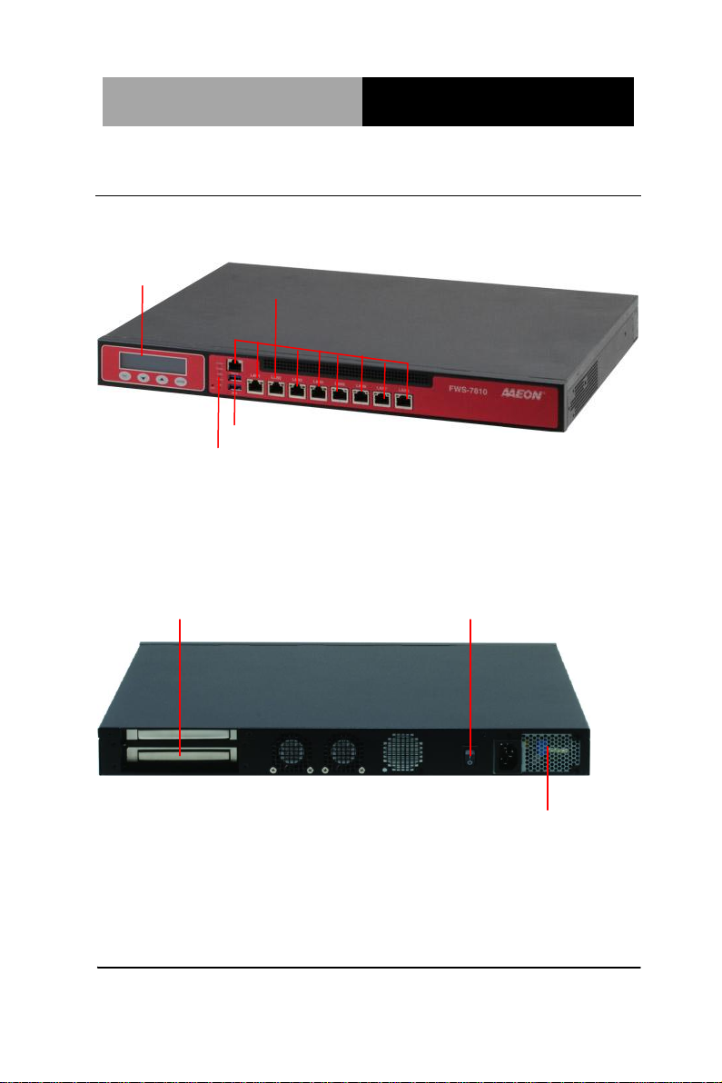
LCM Panel
LED
10/100/1000Base-TX x 9
USB2.0 x 2
Expansion Slots
Power Switch
AC Power Input
1.4 General System Information
Front View
Rear View
Chapter 1 General Information 1- 7
Page 14

Network Appliance
FWS- 7810
Chapter
2
Quick
Installation
Guide
Chapter 2 Quick Installation Guide 2-1
Page 15

Network Appliance
FWS- 7810
Always completely disconnect the power cord from
your board whenever you are working on it. Do not
make connections while the power is on, because a
sudden rush of power can damage sensitive
electronic components.
Always ground yourself to remove any static charge
before touching the board. Modern electronic devices
are very sensitive to static electric charges. Use a
grounding wrist strap at all times. Place all electronic
components on a static-dissipative surface or in a
static-shielded bag when they are not in the chassis
2.1 Safety Precautions
The installation is intended for technically qualified personnel who
have experience installing and configuring system boards.
The equipment can be installed in a restricted access location (RAL)
only.
A restricted access location is a site location for equipment where
the following criteria apply:
01. Access can only be gained by service persons or by users who
have been trained on the restrictions and the precautions for this
specific site.
02. Access is by means of at least one of the following, special tool,
lock and key, or other means of security, and is controlled by the
authority responsible for the location.
Safety Precautions:
Risk of explosion if the battery is replaced by an incorrect type. Dispose of
used batteries according to the instructions.
Chapter 2 Quick Installation Guide 2-2
Page 16
Network Appliance
FWS- 7810
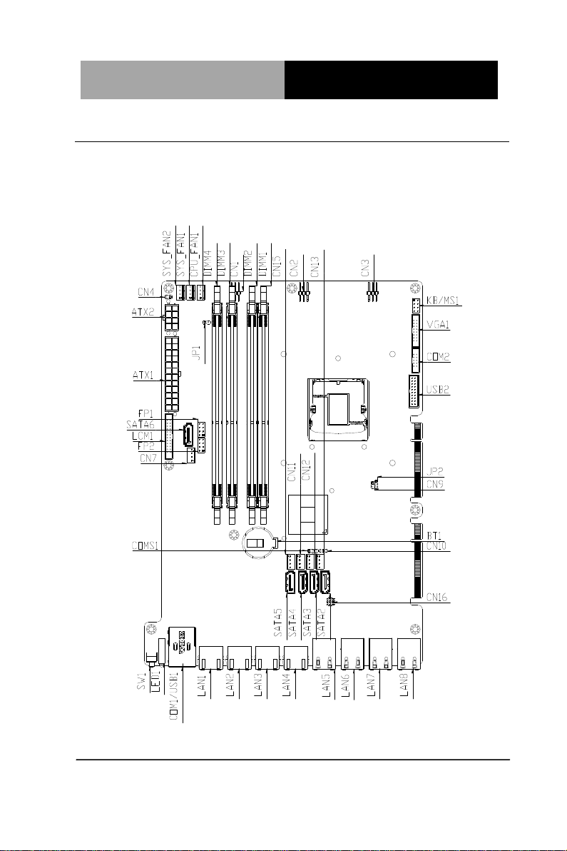
2.2 Location of Connectors
Board of FWS-7810
Component side
Chapter 2 Quick Installation Guide 2-3
Page 17

Network Appliance
FWS- 7810
Solder Side
Chapter 2 Quick Installation Guide 2-4
Page 18
Network Appliance
FWS- 7810
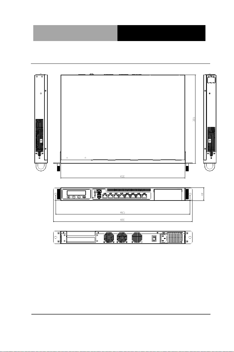
2.3 Mechanical Drawings of FWS-7810
Chapter 2 Quick Installation Guide 2-5
Page 19

Network Appliance
FWS- 7810
Label
Function
JP2
Auto Power Button
CMOS
Clear CMOS
Label
Function
FP1
Front Panel Connector 1
FP2
Front Panel Connector 2
KB/MS1
PS2 KB/MS Pin Header
VGA1
VGA Pin Header
COM2
RS-232 Pin Header
USB2
USB 3.0 Pin Header
DIMM1
DDR3 DIMM Slot
DIMM2
DDR3 DIMM Slot
DIMM3
DDR3 DIMM Slot
DIMM4
DDR3 DIMM Slot
BT1
Battery
SATA1~SATA6
SATA Connector
2.4 List of Jumpers
The board has a number of jumpers that allow you to configure your
system to suit your application.
The table below shows the function of each of the board's jumpers:
2.5 List of Connectors
The board has a number of connectors that allow you to configure
your system to suit your application. The table below shows the
function of each board's connectors:
Chapter 2 Quick Installation Guide 2-6
Page 20

Network Appliance
FWS- 7810
LAN1
10/100/1000 Base-TX Ethernet Connector
LAN2
10/100/1000 Base-TX Ethernet Connector
LAN3
10/100/1000 Base-TX Ethernet Connector
LAN4
10/100/1000 Base-TX Ethernet Connector
LAN5
10/100/1000 Base-TX Ethernet Connector
LAN6
10/100/1000 Base-TX Ethernet Connector
LAN7
10/100/1000 Base-TX Ethernet Connector
LAN8
10/100/1000 Base-TX Ethernet Connector
CPU_FAN1
4-Pin Fan Connector
SYS_FAN1
4-Pin Fan Connector
SYS_FAN2
4-Pin Fan Connector
CN7
SATA Power Connector
CN11~CN15
SATA Power Connector
CN4
Power Bottom
LCM1
LCM Connector
ATX1
24-Pin ATX Power Connector
ATX2
8-Pin ATX Power Connector
COM1/USB1
COM/USB3 Connector
SW1
Reset Switch (By Control)
Chapter 2 Quick Installation Guide 2-7
Page 21
Network Appliance
FWS- 7810
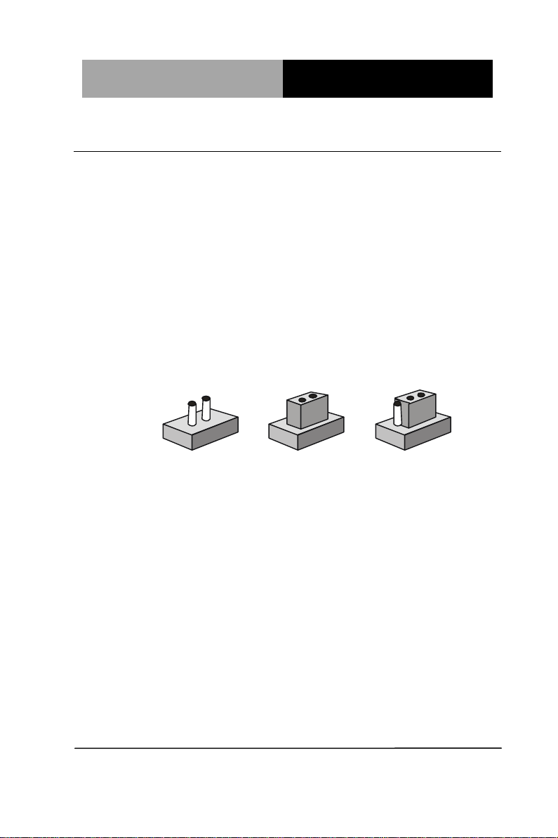
1
2
3
Open Closed Closed 2-3
2.6 Setting Jumpers
You configure your card to match the needs of your application by
setting jumpers. A jumper is the simplest kind of electric switch. It
consists of two metal pins and a small metal clip (often protected by
a plastic cover) that slides over the pins to connect them. To “close”
a jumper you connect the pins with the clip.
To “open” a jumper you remove the clip. Sometimes a jumper will
have three pins, labeled 1, 2 and 3. In this case you would connect
either pins 1 and 2 or 2 and 3.
A pair of needle-nose pliers may be helpful when working with
jumpers.
If you have any doubts about the best hardware configuration for
your application, contact your local distributor or sales
representative before you make any change.
Generally, you simply need a standard cable to make most
connections.
Chapter 2 Quick Installation Guide 2-8
Page 22

Network Appliance
FWS- 7810
CMOS
Function
1-2
Protected (Default)
2-3
Clear
JP2
Function
1-2
Power ON by Button (Default)
2-3
Auto Power ON
Pin
Signal
Pin
Signal
1
External Speaker (+)
2
Key Board Lock (+)
3
NC 4 GND
5
Internal Buzzer (-)
6
I2C Bus SMB Clock
7
External Speaker (-)
8
I2C Bus SMB Data
Pin
Signal
Pin
Signal
1
Power On Button (+)
2
Reset Switch (+)
3
Power On Button (-)
4
Reset Switch (-)
5
HDD LED (+)
6
Power LED (+)
7
HDD LED (-)
8
Power LED (-)
2.7 Clear CMOS (CMOS)
2.8 Auto Power Button (JP2)
2.9 Front Panel Connector (FP1)
Note:
Internal Buzzer Enable: Close Pin 5,7
2.10 Front Panel Connector (FP2)
Chapter 2 Quick Installation Guide 2-9
Page 23

Network Appliance
FWS- 7810
Pin
Signal
Pin
Signal
1
VCC
20
NC 2 USB3_RX1_DN_C
19
VCC
3
USB3_RX1_DP_C
18
USB3_RX2_DN_C
4
GND
17
USB3_RX2_DP_C
5
USB3_TX1_DN_C
16
GND
6
USB3_TX1_DP_C
15
USB3_TX2_DN_C
7
GND
14
USB3_TX2_DP_C
8
USBP_0N_C
13
GND
9
USBP_0P_C
12
USBP_1N_C
10
NC
11
USBP_1P_C
2.11 USB3.0 Port PIN Header
Chapter 2 Quick Installation Guide 2-10
Page 24
Network Appliance
FWS- 7810
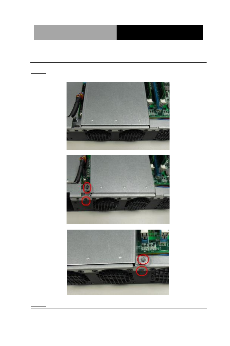
2.12 Installing the CPU and the Heat Sink
Step 1: Loosen the screws and remove the fan duct
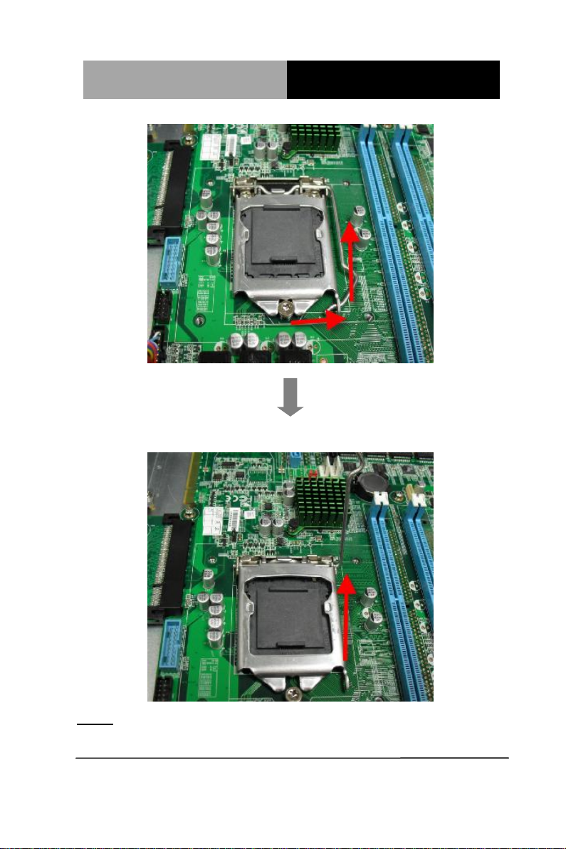
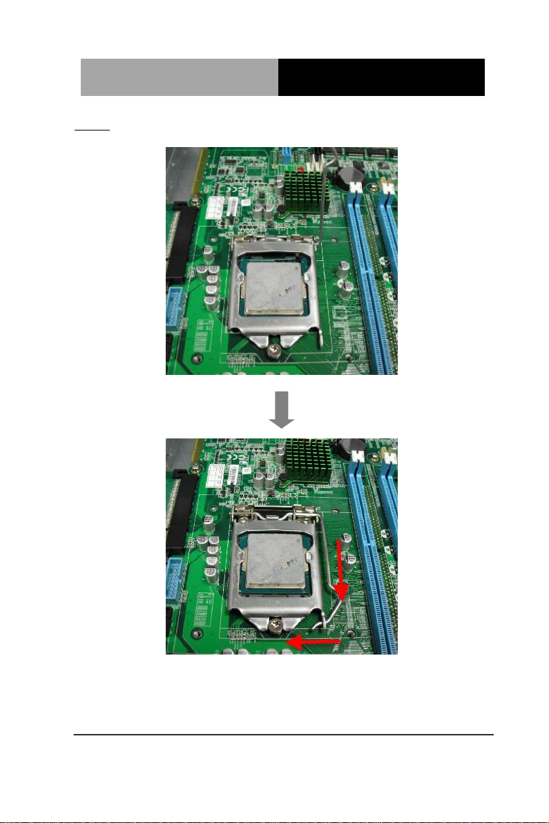
Step 2: Release the lock pole of the CPU bracket
Chapter 2 Quick Installation Guide 2-11
Page 25
Network Appliance
FWS- 7810
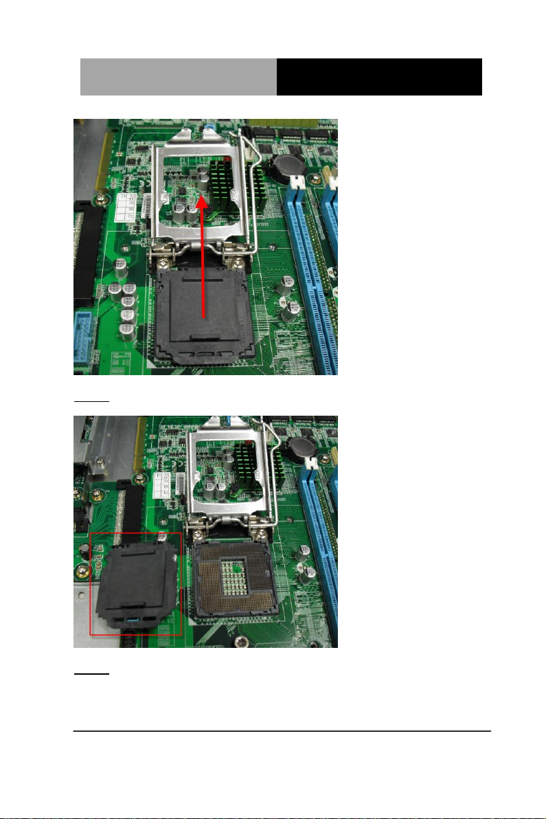
Step 3: Lift up the CPU bracket
Chapter 2 Quick Installation Guide 2-12
Page 26
Network Appliance
FWS- 7810
Step 4 : Lift up the CPU cover
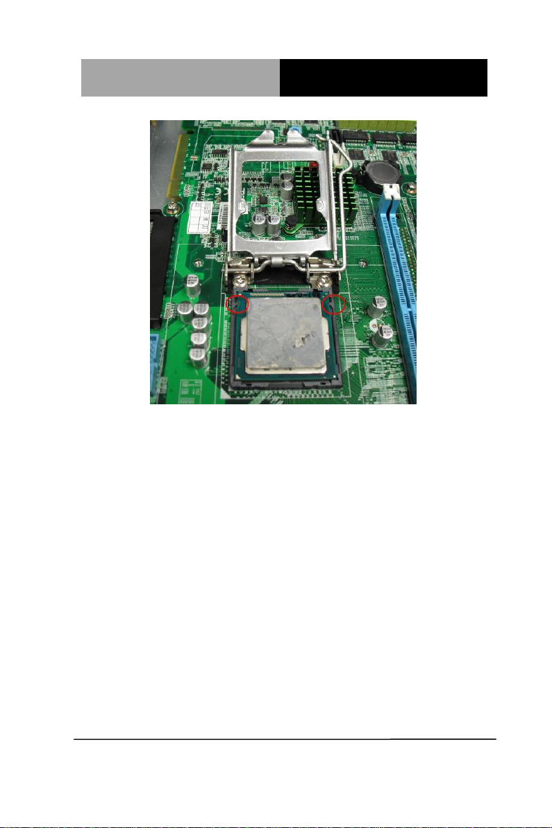
Step 5 : Place the CPU to the socket and have the two fillisters locked
properly
Chapter 2 Quick Installation Guide 2-13
Page 27
Network Appliance
FWS- 7810
Chapter 2 Quick Installation Guide 2-14
Page 28
Network Appliance
FWS- 7810
Step 6 : Close the CPU bracket and lock the pole to the position
Chapter 2 Quick Installation Guide 2-15
Page 29
Network Appliance
FWS- 7810
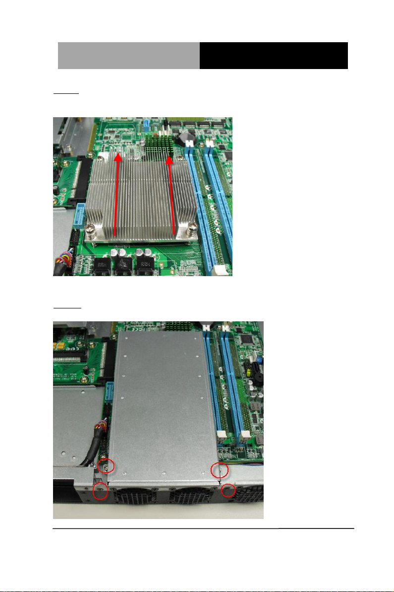
Step 7 : Cover the Heatsink on the CPU and watch out the direction
of the Heatsink that did not against the airflow
Step 8: Fasten the four screws to lock the air duct
Chapter 2 Quick Installation Guide 2-16
Page 30
Network Appliance
FWS- 7810
2.13 Installing the Two 2.5” Hard Disk Drive (HDD)
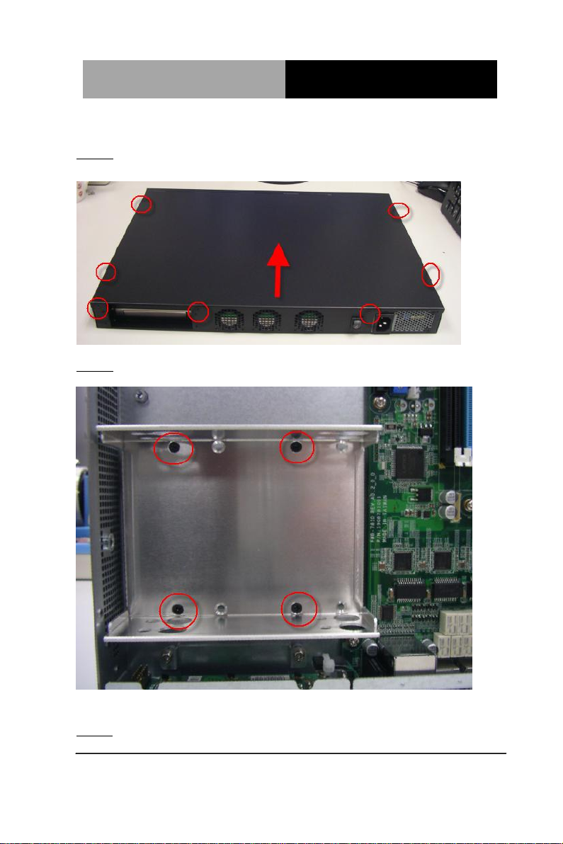
Step 1: Unscrew the upper lid
Step 2: Unfasten the four screws
Step 3: put the screw into cushion
Chapter 2 Quick Installation Guide 2-17
Page 31

Network Appliance
FWS- 7810
Step 4: put the assembled cushions to the upper place of the 2.5” HDD
bracket
Step 5: put the assembled cushions to the lower place of the 2.5” HDD
Chapter 2 Quick Installation Guide 2-18
Page 32

Network Appliance
FWS- 7810
bracket
Step 6: Lock the HDD to the lower cushions with four screws
Step 7: Lock the second HDD to the upper cushions with four screws
Chapter 2 Quick Installation Guide 2-19
Page 33

Network Appliance
FWS- 7810
Step 8: Lock the HDD bracket to the chassis with four screws
Step 9: Connect the SATA cable and power cable to the HDD in lower place
Chapter 2 Quick Installation Guide 2-20
Page 34

Network Appliance
FWS- 7810
Step 10: Connect the SATA cable and power cable to the HDD in upper
place
Chapter 2 Quick Installation Guide 2-21
Page 35

Network Appliance
FWS- 7810
2.14 Installing the Network Interface Module (NIM)
Step 1: Unfasten the screws on the bottom of chassis
Chapter 2 Quick Installation Guide 2-22
Page 36

Network Appliance
FWS- 7810
Step 2 : Remove the null Module cover or existing LAN module
Chapter 2 Quick Installation Guide 2-23
Page 37

Network Appliance
FWS- 7810
Step 3 : Insert the LAN Module and fasten the screws on the chassis
Chapter 2 Quick Installation Guide 2-24
Page 38

Network Appliance
FWS- 7810
Chapter 2 Quick Installation Guide 2-25
Page 39

Network Appliance
FWS- 7810
部件名称
有毒有害物质或元素
铅
(Pb)
汞
(Hg) 镉 (Cd)
六价铬
(Cr(VI))
多溴联苯
(PBB)
多溴二苯醚
(PBDE)
印刷电路板
及其电子组件
×
○ ○ ○ ○ ○
外部信号
连接器及线材
× ○ ○ ○ ○
○
外壳
× ○ ○ ○ ○
○
中央处理器
与内存
× ○ ○ ○ ○
○
硬盘
× ○ ○ ○ ○
○
电源
×
○ ○ ○ ○ ○
O:表示该有毒有害物质在该部件所有均质材料中的含量均在
SJ/T 11363-2006 标准规定的限量要求以下。
X:表示该有毒有害物质至少在该部件的某一均质材料中的含量超出
SJ/T 11363-2006 标准规定的限量要求。
备注:
一、此产品所标示之环保使用期限,系指在一般正常使用状况下。
二、上述部件物质中央处理器、内存、硬盘、电源为选购品。
Below Table for China RoHS Requirements
产品中有毒有害物质或元素名称及含量
AAEON Boxer/ Industrial System
Chapter 2 Quick Installation Guide 2-26
Page 40

Network Appliance
FWS- 781 0
Chapter
3
AMI
BIOS Setup
Chapter 3 AMI BIOS Setup 3-1
Page 41

Network Appliance
FWS- 781 0
3.1 System Test and Initialization
These routines test and initialize board hardware. If the routines
encounter an error during the tests, you will either hear a few short
beeps or see an error message on the screen. There are two kinds
of errors: fatal and non-fatal. The system can usually continue the
boot up sequence with non-fatal errors.
System configuration verification
These routines check the current system configuration against the
values stored in the CMOS memory. If they do not match, the
program outputs an error message. You will then need to run the
BIOS setup program to set the configuration information in memory.
There are three situations in which you will need to change the
CMOS settings:
1. You are starting your system for the first time
2. You have changed the hardware attached to your system
3. The CMOS memory has lost power and the configuration
information has been erased.
The FWS-7810 CMOS memory has an integral lithium battery
backup for data retention. However, you will need to replace the
complete unit when it finally runs down.
Chapter 3 AMI BIOS Setup 3-2
Page 42

Network Appliance
FWS- 781 0
3.2 AMI BIOS Setup
AMI BIOS ROM has a built-in Setup program that allows users to
modify the basic system configuration. This type of information is
stored in battery-backed CMOS RAM so that it retains the Setup
information when the power is turned off.
Entering Setup
Power on the computer and press <Del> or <F2> immediately. This
will allow you to enter Setup.
Main
Set the date, use tab to switch between date elements.
Advanced
Enable disable boot option for legacy network devices.
Chipset
host bridge parameters.
Boot
Enables/disable quiet boot option.
Security
Set setup administrator password.
Save&Exit
Exit system setup after saving the changes.
Chapter 3 AMI BIOS Setup 3-3
Page 43

Network Appliance
FWS- 781 0
Setup Menu
Setup submenu: Main
Chapter 3 AMI BIOS Setup 3-4
Page 44

Network Appliance
FWS- 781 0
Setup submenu: Advanced
Chapter 3 AMI BIOS Setup 3-5
Page 45

Network Appliance
FWS- 781 0
Super IO Configuration
Chapter 3 AMI BIOS Setup 3-6
Page 46

Network Appliance
FWS- 781 0
Serial Port
Disabled
Enabled
Enable or Disable Serial Port (COM)
Serial Port
Auto
IO=3F8h; IRQ=4;
IO=3F8h; IRQ=3,4,5,6,7,9,10,11,12;
IO=2F8h; IRQ=3,4,5,6,7,9,10,11,12;
IO=3E8h; IRQ=3,4,5,6,7,9,10,11,12;
IO=2E8h; IRQ=3,4,5,6,7,9,10,11,12;
Select an optimal setting for Super IO device.
Serial Port 1 Configuration
Options summary:
Chapter 3 AMI BIOS Setup 3-7
Page 47

Network Appliance
FWS- 781 0
Serial Port
Disabled
Enabled
Enable or Disable Serial Port (COM)
Serial Port
Auto
IO=2F8h; IRQ=3;
IO=3F8h; IRQ=3,4,5,6,7,9,10,11,12;
IO=2F8h; IRQ=3,4,5,6,7,9,10,11,12;
IO=3E8h; IRQ=3,4,5,6,7,9,10,11,12;
IO=2E8h; IRQ=3,4,5,6,7,9,10,11,12;
Select an optimal setting for Super IO device.
Serial Port 2 Configuration
Options summary:
Chapter 3 AMI BIOS Setup 3-8
Page 48

Network Appliance
FWS- 781 0
Parallel Port
Disabled
Enabled
Enable or Disable Serial Port (COM)
Change Settings
Auto
IO=378h; IRQ=5;
IO=378h; IRQ=5,6,7,9,10,11,12;
IO=278h; IRQ=5,6,7,9,10,11,12;
IO=3BCh;IRQ=5,6,7,9,10,11,12;
Select an optimal setting for Supoer IO device.
Device Mode
Standard Parallel Port Mode
EPP Mode
ECP Mode
EPP Mode & ECP Mode
Change the Printer Port mode.
Parallel Port Configuration
Options summary:
Chapter 3 AMI BIOS Setup 3-9
Page 49

Network Appliance
FWS- 781 0
H/W Monitor
Chapter 3 AMI BIOS Setup 3-10
Page 50

Network Appliance
FWS- 781 0
Smart Fan Mode
Full on Mode
Automatic Mode
Manual Mode
Smart Fan Mode Select
Fan off temperature limit
15 (0-127)
Fan will of when temperature lower than this limit.
Fan start temperature limit
45 (0-127)
Fan will work when temperature higher than this limit.
Fan start PWM
35 (0-255)
Fan will start with this PWM value(Range 0-255).
Smart Fan Function
Options summary:
Chapter 3 AMI BIOS Setup 3-11
Page 51

Network Appliance
FWS- 781 0
PWM SLOPE SETTING
0.125 PWM
0.25 PWM
0.5 PWM
1 PWM
2 PWM
4 PWM
8 PWM
15.875 PWM
PWM SLOPE Selection
Chapter 3 AMI BIOS Setup 3-12
Page 52

Network Appliance
FWS- 781 0
Console Redirection
Disabled (COM2)
Enabled (COM1)
Console Redirection Enabled or Disabled.
Serial Port Console Redirection
Options summary:
Chapter 3 AMI BIOS Setup 3-13
Page 53

Network Appliance
FWS- 781 0
Terminal Type
VT100
VT100+
VT-UTF8
ANSI
Emulation: ANSI: Extended ASCII char set. VT100: ASCII char set. VT100+:
Extends VT100 to support color, function keys, etc. VT-UTF8: Uses UTF8
encoding to map Unicode chars onto 1 or more bytes.
Bits per second
9600
19200
38400
57600
115200
Selects serial port transmission speed. The speed must be matched on the other
side. Long or noisy lines may require lower speeds.
Data Bits
7 8 Data Bits
Console Redirection Settings
Options summary:
Chapter 3 AMI BIOS Setup 3-14
Page 54

Network Appliance
FWS- 781 0
Parity
None
Even
Odd
Mark
Space
A parity bit can be sent with the data bits to detect some transmission errors. Even:
parity bit is 0 if the num of 1’s in the data bits is even. Odd: parity bit is 0 if num of
1’s in the data bits is odd. Mark: parity bit is always 1. Space: Parity bit is always 0.
Mark and Space Parity do not allow for error detection.
Stop Bits
1
2
Stop bits indicate the end of a serial data packet. ( A start bit indicates the
beginning). The standard setting is 1 stop bit. Communication with slow devices
may require more than 1 stop bit.
Flow Control
None
Hardware RTS/CTS
Flow control can prevent data loss from buffer overflow. When sending data, if the
receiving buffers are full, a ‘stop’ signal can be sent to stop the data flow. Once the
buffers are empty, a ‘start’ signal can be sent to re-start the flow. Hardware flow
control uses two wires to send start/stop signals.
Chapter 3 AMI BIOS Setup 3-15
Page 55

Network Appliance
FWS- 781 0
VT-UTF8 Combo Key Support
Disabled
Enabled
Enable VT-UTF8 Combination Key Support for ANSI/VT100 terminals
Recorder Mode
Disabled
Enabled
On this mode enabled only text will be send. This is to capture Terminal data.
Resolution 100x31
Disabled
Enabled
Enables or disables extended terminal resolution
Legacy OS Redirection Resolution
80x24
80x25
On Legacy OS, the Number of Rows and Columns supported redirection
Putty KeyPad
VT100
LINUX
XTERMR6
SCO
ESCN
VT400
Select FunctionKey and KeyPad on Putty.
Redirection After BIOS POST
Always Enable
BootLoader
The Setting Specify if BootLoader is selected than Legacy console redirection is
disabled before booting to Legacy OS. Default value is Always Enable which
means Legacy console Redirection is enabled for Legacy OS.
Chapter 3 AMI BIOS Setup 3-16
Page 56

Network Appliance
FWS- 781 0
Power Mode
ATX Type
AT Type
Select Power Supply Mode.
ACPI Sleep State
Suspend Disabled
S3 only (Suspend to RAM)
Select ACPI sleep state the system will enter when the SUSPEND button is
pressed.
Restore AC Power Loss
Power Off
Power On
Last State
Select AC power state when power is re-applied after a power failure.
Resume on Ring
Disabled
Enabled
Enable/Disable Resume from RI# signal.
Resume on PCIE
Disabled
Enabled
Enable/Disable Resume from PCIE signal.
Wake system with Fixed Time
Disabled
Enabled
Enable or disable System wake on alarm event. When enable, System will wake
on the hr::min::sec specified.
Wake up day
0
Select 0 for daily system wake up, 1-31 for which day of month that you would like
the system to wake up.
Wake up hour
0
Select 0-23 For example enter 3 for 3am and 15 for 3pm.
Wake up minute
0
0-59
Wake up second
0
0-59
Wake system with Dynamic Time
Disabled
Enabled
Enable or disable System wake on alarm event. When enabled, System will wake
on the current time + Increase minute(s).
Wake up minute increase
1
1-5
Power Management
Options summary:
Chapter 3 AMI BIOS Setup 3-17
Page 57

Network Appliance
FWS- 781 0
CPU Configuration
Chapter 3 AMI BIOS Setup 3-18
Page 58

Network Appliance
FWS- 781 0
Hyper-threading
Disabled
Enabled
Enabled for Windows XP and Linux (OS optimized for Hyper-Threading
Technology) and Disabled for other OS (OS not optimized for Hyper-Threading
Technology). When Disabled only on thread per enabled core is enabled.
Intel Virtualization Technology
Disabled
Enabled
When enabled, a VMM can utilize the additional hardware capabilities provided by
Vanderpool Technology.
Turbo Mode
Disabled
Enabled
Turbo Mode
Options summary :
Chapter 3 AMI BIOS Setup 3-19
Page 59

Network Appliance
FWS- 781 0
SATA Controller(s)
Disabled
Enabled
Enable or disable SATA Device.
SATA Mode Selection
IDE
AHCI
RAID
Determines how SATA controller(s) operate.
SATA Configuration (IDE)
Options summary :
Chapter 3 AMI BIOS Setup 3-20
Page 60

Network Appliance
FWS- 781 0
SATA Controller Speed
Disabled
Enabled
Enable or disable SATA Device.
SATA Mode Selection
Default
Gen1
Gen2
Gen3
Indicates the maximum speed the SATA controller can support.
Port
Disabled
Enabled
Enable or Disable SATA Port
Hot Plug
Disabled
Enabled
Designates this port as Hot Pluggable.
External SATA
Disabled
Enabled
External SATA Support.
SATA Configuration (AHCI)
Options summary :
Chapter 3 AMI BIOS Setup 3-21
Page 61

Network Appliance
FWS- 781 0
SATA Device Type
Hard Disk Drive
Solid State Drive
Indentify the SATA port is connected to Solid State Drive or Hard Disk Drive.
Spin Up Device
Disabled
Enabled
On an edge detect from 0 to 1, the PCH starts a COMRESET initialization
sequence to device.
Chapter 3 AMI BIOS Setup 3-22
Page 62

Network Appliance
FWS- 781 0
SATA Controller Speed
Disabled
Enabled
Enable or disable SATA Device.
SATA Mode Selection
Default
Gen1
Gen2
Gen3
Indicates the maximum speed the SATA controller can support.
Port
Disabled
Enabled
Enable or Disable SATA Port
Hot Plug
Disabled
Enabled
Designates this port as Hot Pluggable.
External SATA
Disabled
Enabled
External SATA Support.
SATA Configuration (RAID)
Options summary :
Chapter 3 AMI BIOS Setup 3-23
Page 63

Network Appliance
FWS- 781 0
SATA Device Type
Hard Disk Drive
Solid State Drive
Indentify the SATA port is connected to Solid State Drive or Hard Disk Drive.
Spin Up Device
Disabled
Enabled
On an edge detect from 0 to 1, the PCH starts a COMRESET initialization
sequence to device.
Chapter 3 AMI BIOS Setup 3-24
Page 64

Network Appliance
FWS- 781 0
Legacy USB Support
Enabled
Disabled
Auto
Enables Legacy USB support. AUTO option disables legacy support if no USB
devices are connected. DISABLE option will keep USB device available only for
EFI applications.
USB Configuration
Options summary:
Chapter 3 AMI BIOS Setup 3-25
Page 65

Network Appliance
FWS- 781 0
STATUS LED CTRL
LED OFF
RED LED ON
RED LED BLINK
RED LED FAST BLINK
GREEN LED ON
GREEN LED BLINK
GREEN LED FAST BLINK
STATUS LED CTRL help.
LAN kit Power ON
Bypass
PassTru
Setting LAN kit function behavior when power on.(Bypass/Pass Through)
LAN kit Power Off
Bypass
PassTru
Setting LAN kit function behavior when power off.(Bypass/Pass Through)
LAN Bypass Configuration
Options summary :
Chapter 3 AMI BIOS Setup 3-26
Page 66

Network Appliance
FWS- 781 0
WDT
Bypass
Reset
WDT function select, Reset: Reset System. Bypass: Reset LAN kits to Bypass
mode.
Chapter 3 AMI BIOS Setup 3-27
Page 67

Network Appliance
FWS- 781 0
Setup submenu: Chipset
Chapter 3 AMI BIOS Setup 3-28
Page 68

Network Appliance
FWS- 781 0
PCI-E LAN Port n
Disabled
Enabled
Control the PCI Express Root Port.
PCH-IO Configuration
Options summary:
Chapter 3 AMI BIOS Setup 3-29
Page 69

Network Appliance
FWS- 781 0
VT-d
Disabled
Enabled
Check to enable VT-d function on MCH.
System Agent (SA) Configuration
Options summary :
Memory Configuration
Chapter 3 AMI BIOS Setup 3-30
Page 70

Network Appliance
FWS- 781 0
Chapter 3 AMI BIOS Setup 3-31
Page 71

Network Appliance
FWS- 781 0
Quite Boot
Disabled
Enabled
Enables or disables Quiet Boot option.
Launch 82574L # PXE
Disabled
Enabled
Enable or Disable Legacy Boot Option for 82574 # .
Boot
Options summary :
Chapter 3 AMI BIOS Setup 3-32
Page 72

Network Appliance
FWS- 781 0
Security
Change User/Supervisor Password
You can install a Supervisor password, and if you install a supervisor
password, you can then install a user password. A user password does
not provide access to many of the features in the Setup utility.
If you highlight these items and press Enter, a dialog box appears which
lets you enter a password. You can enter no more than six letters or
numbers. Press Enter after you have typed in the password. A second
dialog box asks you to retype the password for confirmation. Press Enter
after you have retyped it correctly. The password is required at boot time,
or when the user enters the Setup utility.
Removing the Password
Highlight this item and type in the current password. At the next dialog
box press Enter to disable password protection.
Chapter 3 AMI BIOS Setup 3-33
Page 73

Network Appliance
FWS- 781 0
Setup submenu: Exit
Chapter 3 AMI BIOS Setup 3-34
Page 74

Network Appliance
FWS- 781 0
Chapter
4
Driver
Installation
Chapter 4 Driver Installation 4-1
Page 75

Network Appliance
FWS- 7 8 1 0
The FWS-7810 comes with an AutoRun DVD-ROM that contains all
drivers and utilities that can help you to install the driver
automatically.
Insert the driver DVD, the driver DVD-title will auto start and show
the installation guide. If not, please follow the sequence below to
install the drivers.
Follow the sequence below to install the drivers:
Step 1 – Install Chipset Driver
Step 2 – Install VGA Driver
Step 3 – Install USB3.0 Driver
Step 4 – Install LAN Driver
Step 5 – Install ME Driver
Please read instructions below for further detailed installations.
Chapter 4 Driver Installation 4-2
Page 76

Network Appliance
FWS- 781 0
4.1 Installation
Insert the FWS-7810 DVD-ROM into the DVD-ROM drive and
install the drivers from Step 1 to Step 5 in order.
Step 1 – Install Chipset Driver
1. Click on the Step1 - Chipset folder and double click on
the infinst_autol.exe file
2. Follow the instructions that the window shows
3. The system will help you install the driver automatically
Step 2 – Install VGA Driver
1. Click on the Step2 - VGA folder and double click on the
Setup.exe file
2. Follow the instructions that the window shows
3. The system will help you install the driver automatically
Step 3 – Install USB3.0 Driver
1. Click on the Step3 - USB3.0 folder and double click on
the Setup.exe file
2. Follow the instructions that the window shows
3. The system will help you install the driver automatically
Step 4 – Install LAN Driver
1. Click on the Step4 - LAN folder and double click on the
Autorun.exe file
Chapter 4 Driver Installation 4-3
Page 77

Network Appliance
FWS- 7 8 1 0
2. Follow the instructions that the window shows
3. The system will help you install the driver automatically
Step 5 – Install ME Driver
1. Click on the Step5 - ME folder and double click on the
Setup.exe file
2. Follow the instructions that the window shows
3. The system will help you install the driver automatically
Chapter 4 Driver Installation 4-4
Page 78

Network Appliance
FWS- 781 0
Appendix
A
Programming the
Watchdog Timer
Appendix A Programming the Watchdog Timer A-1
Page 79

Network Appliance
FWS- 781 0
Table 1 : SuperIO relative register table
Default Value
Note
Index
0x2E(Note1)
SIO MB PnP Mode Index Register
0x2E or 0x4E
Data
0x2F(Note2)
SIO MB PnP Mode Data Register
0x2F or 0x4F
Table 2 : Watchdog relative register table
LDN
Register
BitNum
Value
Note
Timer Counter
0x07(Note3)
0x73(Note4)
(Note24)
Time of watchdog timer
(0~255)
This register is byte
access
Counting Unit
0x07(Note5)
0x72(Note6)
7(Note7)
1(Note8)
Select time unit.
1: second
0: minute
Watchdog
Enable
(KRST)
0x07(Note9)
0x72(Note10)
4(Note11)
1(Note12)
0: Disable
1: Enable
Timeout Status
0x07(Note13)
0x71(Note14)
0(Note15)
1
1: Clear timeout status
A.1 Watchdog Timer Initial Program
Appendix A Programming the Watchdog Timer A-2
Page 80

Network Appliance
FWS- 781 0
************************************************************************************
// SuperIO relative definition (Please reference to Table 1)
#define byte SIOIndex //This parameter is represented from Note1
#define byte SIOData //This parameter is represented from Note2
#define void IOWriteByte(byte IOPort, byte Value);
#define byte IOReadByte(byte IOPort);
// Watch Dog relative definition (Please reference to Table 2)
#define byte TimerLDN //This parameter is represented from Note3
#define byte TimerReg //This parameter is represented from Note4
#define byte TimerVal // This parameter is represented from Note24
#define byte UnitLDN //This parameter is represented from Note5
#define byte UnitReg //This parameter is represented from Note6
#define byte UnitBit //This parameter is represented from Note7
#define byte UnitVal //This parameter is represented from Note8
#define byte EnableLDN //This parameter is represented from Note9
#define byte EnableReg //This parameter is represented from Note10
#define byte EnableBit //This parameter is represented from Note11
#define byte EnableVal //This parameter is represented from Note12
#define byte StatusLDN // This parameter is represented from Note13
#define byte StatusReg // This parameter is represented from Note14
#define byte StatusBit // This parameter is represented from Note15
************************************************************************************
Appendix A Programming the Watchdog Timer A-3
Page 81

Network Appliance
FWS- 781 0
************************************************************************************
VOID Main(){
// Procedure : AaeonWDTConfig
// (byte)Timer : Time of WDT timer.(0x00~0xFF)
// (boolean)Unit : Select time unit(0: second, 1: minute).
AaeonWDTConfig();
// Procedure : AaeonWDTEnable
// This procudure will enable the WDT counting.
AaeonWDTEnable();
}
************************************************************************************
Appendix A Programming the Watchdog Timer A-4
Page 82

Network Appliance
FWS- 781 0
************************************************************************************
// Procedure : AaeonWDTEnable
VOID AaeonWDTEnable (){
WDTEnableDisable(EnableLDN, EnableReg, EnableBit, 1);
}
// Procedure : AaeonWDTConfig
VOID AaeonWDTConfig (){
// Disable WDT counting
WDTEnableDisable(EnableLDN, EnableReg, EnableBit, 0);
// Clear Watchdog Timeout Status
WDTClearTimeoutStatus();
// WDT relative parameter setting
WDTParameterSetting();
}
VOID WDTEnableDisable(byte LDN, byte Register, byte BitNum, byte Value){
SIOBitSet(LDN, Register, BitNum, Value);
}
VOID WDTParameterSetting(){
// Watchdog Timer counter setting
SIOByteSet(TimerLDN, TimerReg, TimerVal);
// WDT counting unit setting
SIOBitSet(UnitLDN, UnitReg, UnitBit, UnitVal);
}
VOID WDTClearTimeoutStatus(){
SIOBitSet(StatusLDN, StatusReg, StatusBit, 1);
}
************************************************************************************
Appendix A Programming the Watchdog Timer A-5
Page 83

Network Appliance
FWS- 781 0
************************************************************************************
VOID SIOEnterMBPnPMode(){
Switch(SIOIndex){
Case 0x2E:
IOWriteByte(SIOIndex, 0x87);
IOWriteByte(SIOIndex, 0x01);
IOWriteByte(SIOIndex, 0x55);
IOWriteByte(SIOIndex, 0x55);
Break;
Case 0x4E:
IOWriteByte(SIOIndex, 0x87);
IOWriteByte(SIOIndex, 0x01);
IOWriteByte(SIOIndex, 0x55);
IOWriteByte(SIOIndex, 0xAA);
Break;
}
}
VOID SIOExitMBPnPMode(){
IOWriteByte(SIOIndex, 0x02);
IOWriteByte(SIOData, 0x02);
}
VOID SIOSelectLDN(byte LDN){
IOWriteByte(SIOIndex, 0x07); // SIO LDN Register Offset = 0x07
IOWriteByte(SIOData, LDN);
}
************************************************************************************
Appendix A Programming the Watchdog Timer A-6
Page 84

Network Appliance
FWS- 781 0
************************************************************************************
VOID SIOBitSet(byte LDN, byte Register, byte BitNum, byte Value){
Byte TmpValue;
SIOEnterMBPnPMode();
SIOSelectLDN(byte LDN);
IOWriteByte(SIOIndex, Register);
TmpValue = IOReadByte(SIOData);
TmpValue &= ~(1 << BitNum);
TmpValue |= (Value << BitNum);
IOWriteByte(SIOData, TmpValue);
SIOExitMBPnPMode();
}
VOID SIOByteSet(byte LDN, byte Register, byte Value){
SIOEnterMBPnPMode();
SIOSelectLDN(LDN);
IOWriteByte(SIOIndex, Register);
IOWriteByte(SIOData, Value);
SIOExitMBPnPMode();
}
************************************************************************************
Appendix A Programming the Watchdog Timer A-7
Page 85

Network Appliance
FWS- 7810
Appendix
B
I/O Information
Appendix B I/O Information B-1
Page 86

Network Appliance
FWS- 7810
B.1 I/O Address Map
Appendix B I/O Information B-2
Page 87

Network Appliance
FWS- 7810
B.2 Memory Address Map
Appendix B I/O Information B-3
Page 88

Network Appliance
FWS- 7810
B.3 IRQ Mapping Chart
Appendix B I/O Information B-4
Page 89

Network Appliance
FWS- 7810
Appendix B I/O Information B-5
Page 90

Network Appliance
FWS- 7810
Appendix B I/O Information B-6
Page 91

Network Appliance
FWS- 7810
Appendix B I/O Information B-7
Page 92

Network Appliance
FWS- 7810
B.4 DMA Channel Assignments
Appendix B I/O Information B-8
Page 93

Network Appliance
FWS- 7810
Appendix
C
Standard LAN Bypass
Platform Setting
Appendix C Standard LAN Bypass Platform Setting C-1
Page 94

Network Appliance
FWS- 7810
Table 1 : Turth Table of Status LED
STA_LED2
STA_LED1
STA_LED0
LED States
0
0
0
LED Off
0
0
1
Red
0
1
0
Red Blinking (Slowly)
0
1
1
Red Blinking (Quickly)
1
0
0
Reserved
1
0
1
Green Blinking (Slowly)
1
1
0
Green Blinking (Quickly)
1
1
1
Green Table 2 : Status LED relative register mapping table
Attribute
Register(I/O)
BitNum
Value
STA_LED2
R/W
0xA02(Note1)
5(Note4)
(Note7)
STA_LED1
R/W
0xA02(Note2)
4(Note5)
(Note7)
STA_LED0
R/W
0xA01(Note3)
2(Note5)
(Note7)
C.1 Status LED
Introduction
FWS-7810 provides a LED indicator which can change the LED status by
AAEON SDK. User is able to program the LED status to express different
status.
Status LED Configuration
Appendix C Standard LAN Bypass Platform Setting C-2
Page 95

Network Appliance
FWS- 7810
Sample Code
************************************************************************************
#define Word LED2Add //This parameter is represented from Note1
#define Word LED1Add //This parameter is represented from Note2
#define Word LED0Add //This parameter is represented from Note3
#define Byte LED2Bit //This parameter is represented from Note4
#define Byte LED1Bit //This parameter is represented from Note5
#define Byte LED0Bit //This parameter is represented from Note6
#define Byte UnitVal //This parameter is represented from Note7
************************************************************************************
VOID SET_Value (Word IoAddr, Byte BitNum,Byte Value){
BYTE TmpValue;
TmpValue = inportb (IoAddr);
TmpValue &= ~(1 << BitNum);
TmpValue |= (Value << BitNum);
outport(IoAddr, TmpValue);
}
************************************************************************************
VOID Main(){
SET_Value (LED2Add, LED2Bit, UnitVal); //Setting STA_LED2
SET_Value (LED1Add, LED1Bit, UnitVal); //Setting STA_LED1
SET_Value (LED0Add, LED0Bit, UnitVal); //Setting STA_LED0
}
************************************************************************************
Appendix C Standard LAN Bypass Platform Setting C-3
Page 96

Network Appliance
FWS- 7810
Table 1 : ID Select table of LAN kit
LAN_ID2
LAN_ID1
LAN_ID0
LAN kit selected
0
0
0
LAN Kit 1 Selected
0
0
1
LAN Kit 2 Selected
0
1
0
LAN Kit 3 Selected
0
1
1
LAN Kit 4 Selected
1
0
0
LAN Kit 5 Selected
1
0
1
LAN Kit 6 Selected
1
1
0
LAN Kit 7 Selected
1
1
1
LAN Kit 8 Selected Table 2 : LAN Bypass relative register table
Function
Description
LAN_ID2
Use for selecting which LAN kit will be configured, refert to
Table 1 of ID Select table of LAN kit.
They should be set before ACT_EN.
LAN_ID1
LAN_ID0
C.2 LAN Bypass
Introduction
FWS-7810 provides LAN Bypass kit and allow uninterrupted network traffic
even if a single in-line appliance is shut down or hangs. Customer can
upgrade to 2 or 4 LAN Bypass kit with options.
LAN Bypass Configuration
Appendix C Standard LAN Bypass Platform Setting C-4
Page 97

Network Appliance
FWS- 7810
PWR_ON
Use for configuring LAN Bypass function behavior to LAN kit,
when system power on.
1: Bypass
0: Pass Through
PWR_OFF
Use for configuring LAN Bypass function behavior to LAN kit,
when system power off.
1: Bypass
0: Pass Through
WDT_EN
Use for configuring WDT function behavior to LAN kit, when
WDT triggered.
0: Normal WDT reset (Default)
1: Force Bypass
ACT_EN
Use for activating programming of LAN kit. It is edge triggering
(falling edge 1 to 0) and should be set to high(1) as its normal
state.
Table 3 : LAN Bypass relative register mapping table
Attribute
Register(I/O)
BitNum
Value
LAN_ID2
R/W
0xA05(Note1)
7(Note8)
(Note15)
LAN_ID1
R/W
0xA05(Note2)
6(Note9)
(Note15)
LAN_ID0
R/W
0xA00(Note3)
6(Note10)
(Note15)
PWR_ON
R/W
0xA00(Note4)
4(Note11)
(Note15)
PWR_OFF
R/W
0xA00(Note5)
2(Note12)
(Note15)
WDT_EN
R/W
0xA00(Note6)
1(Note13)
(Note15)
Appendix C Standard LAN Bypass Platform Setting C-5
Page 98

Network Appliance
FWS- 7810
ACT_EN
R/W
0xA00(Note7)
5(Note14)
(Note15)
************************************************************************************
Sample Code
************************************************************************************
#define Word LAN_ID2 //This parameter is represented from Note1
#define Word LAN_ID1 //This parameter is represented from Note2
#define Word LAN_ID0 //This parameter is represented from Note3
#define Byte PWR_ON //This parameter is represented from Note4
#define Byte PWR_OFF //This parameter is represented from Note5
#define Byte WDT_EN //This parameter is represented from Note6
#define Byte ACT_EN //This parameter is represented from Note7
#define Byte LANID2 //This parameter is represented from Note8
#define Byte LANID1 //This parameter is represented from Note9
#define Byte LANID0 //This parameter is represented from Note10
#define Byte PWR_ON_R //This parameter is represented from Note11
#define Byte PWR_OFF_R //This parameter is represented from Note12
#define Byte WDT_EN_R //This parameter is represented from Note13
#define Byte ACT_EN_R //This parameter is represented from Note14
#define Byte UnitVal //This parameter is represented from Note15
************************************************************************************
VOID Bypass_Active (Word IoAddr, Byte BitNum){ BYTE TmpValue;
TmpValue = inportb (IoAddr);
TmpValue &= ~(1 << BitNum);
outport(IoAddr, TmpValue);
Appendix C Standard LAN Bypass Platform Setting C-6
Page 99

Network Appliance
FWS- 7810
delay100ms();
TmpValue |= (Value << BitNum);
outport(IoAddr, TmpValue);
}
************************************************************************************
************************************************************************************
VOID SET_Value (Word IoAddr, Byte BitNum,Byte Value){ BYTE TmpValue;
TmpValue = inportb (IoAddr);
TmpValue &= ~(1 << BitNum);
TmpValue |= (Value << BitNum);
outport(IoAddr, TmpValue);
}
************************************************************************************
VOID Main(){
//Select LAN kit refer to table 1
SET_Value (LAN_ID2, LANID2, UnitVal);
SET_Value (LAN_ID1, LANID1, UnitVal);
SET_Value (LAN_ID0, LANID1, UnitVal);
//Set the PWR_ON parameter
SET_Value (PWR_ON, PWR_ON_R, UnitVal);
//Set the PWR_OFF parameter
SET_Value (PWR_OFF, PWR_OFF_R, UnitVal);
//Set the WDT_EN parameter
SET_Value (PWR_OFF, PWR_OFF_R, UnitVal);
//Active LAN Bypass setting
Appendix C Standard LAN Bypass Platform Setting C-7
Page 100

Network Appliance
FWS- 7810
Bypass_Active (ACT_EN, ACT_EN_R);
}
************************************************************************************
Appendix C Standard LAN Bypass Platform Setting C-8
 Loading...