

Page 1

Network Appliance
FWS- 2200
FWS-2200
Desktop
Network Appliance Platform
2.5” SATA HDD, CF SATA Socket
6 LAN Ports
2 USB2.0, 1 COM for Console
1 Mini PCI
FWS-2200 Manual 4th Ed.
April 30, 2014
Page 2

Network Appliance
FWS- 2200
Copyright Notice
This document is copyrighted, 2014. All rights are reserved. The
original manufacturer reserves the right to make improvements to the
products described in this manual at any time without notice.
No part of this manual may be reproduced, copied, translated, or
transmitted in any form or by any means without the prior written
permission of the original manufacturer. Information provided in this
manual is intended to be accurate and reliable. However, the original
manufacturer assumes no responsibility for its use, or for any infringements upon the rights of third parties that may result from its
use.
The material in this document is for product information only and is
subject to change without notice. While reasonable efforts have been
made in the preparation of this document to assure its accuracy,
AAEON assumes no liabilities resulting from errors or omissions in
this document, or from the use of the information contained herein.
AAEON reserves the right to make changes in the product design
without notice to its users.
i
Page 3

Network Appliance
FWS- 2200
Acknowledgments
All other products’ name or trademarks are properties of their
respective owners.
Intel® and Atom™ are trademarks of Intel® Corporation.
AMI is a trademark of American Megatrends Inc.
CompactFlash™ is a trademark of the Compact Flash
Association.
Microsoft Windows® is a registered trademark of Microsoft Corp.
All other product names or trademarks are properties of their
respective owners.
ii
Page 4

Network Appliance
FWS- 2200
Caution
There is a danger of explosion if the battery is incorrectly replaced.
Replace only with the same or equivalent type recommended by the
manufacturer. Dispose of used batteries according to the
manufacturer’s instructions and your local government’s recycling or
disposal directives.
Attention:
Il y a un risque d’explosion si la batterie est remplacée de façon incorrecte.
Ne la remplacer qu’avec le même modèle ou équivalent recommandé par le
constructeur. Recycler les batteries usées en accord avec les instructions du
fabricant et les directives gouvernementales de recyclage.
iii
Page 5

Network Appliance
FWS- 2200
Packing List
Before you begin installing your card, please make sure that the
following materials have been shipped:
FWS-2200
CD-ROM for manual (in PDF format) and drivers
D-sub 9-pin Cable x 1
Rubber Foots
60W Power Adapter
SATA Power Cable x 1
SATA Cable x 1
If any of these items should be missing or damaged, please
contact your distributor or sales representative immediately.
Note:
VGA Cable is an optional accessory. Please purchase those
cables according to the following item numbers.
M0422000020 Ear Bracket
1700160253 VGA Cable
iv
Page 6

Network Appliance
FWS- 2200
Contents
Chapter 1 General Information
1.1 Introduction .......................................................... 1-2
1.2 Features .............................................................. 1-3
1.3 Specifications ...................................................... 1-4
1.4 General System Information ............................... 1-7
Chapter 2 Quick Installation Guide
2.1 Safety Precautions .............................................. 2-2
2.2 Location of Connectors of Main Board ................ 2-3
2.3 Mechanical Drawing of Main Board .................... 2-4
2.4 List of Jumpers .................................................... 2-5
2.5 List of Connectors ............................................... 2-5
2.6 Setting Jumpers .................................................. 2-7
2.7 CMOS Setting Selection (JP3) ............................ 2-8
2.8 Auto PWRBTN Selection (JP6) ........................... 2-8
2.9 4-pin ATX Power Connector (CN9) ..................... 2-8
2.10 Front Panel Connector (FP1) ............................ 2-8
2.11 Pin Header (USB2)............................................ 2-9
2.12 RS-232 Box Header (COM2) ............................ 2-9
2.13 SATA Connector (SATA 1) ............................... 2-9
2.14 CF-SATA Connector (CFD1) ............................ 2-10
2.15 Software Programmable Button (RSW1) .......... 2-11
2.16 Analog Display (VGA1) ..................................... 2-11
v
Page 7

Network Appliance
FWS- 2200
2.17 Installing the Hard Disk Drive ............................ 2-12
Chapter 3 AMI BIOS Setup
3.1 System Test and Initialization ............................. 3-2
3.2 AMI BIOS Setup .................................................. 3-3
Chapter 4 Driver Installation
4.1 Installation ........................................................... 4-3
Appendix A Programming the Watchdog Timer
A.1 Programming .................................................. A-2
A.2 W83627DHG Watchdog Timer Initial ProgramA-6
Appendix B I/O Information
B.1 I/O Address Map ............................................. B-2
B.2 Memory Address Map ..................................... B-4
B.3 IRQ Mapping Chart ......................................... B-5
B.4 DMA Channel Assignments ............................ B-8
Appendix C Standard Firewall Platform Setting
C.1 Standard Firewall Platform Setting ................. C-2
C.2 Status LED Sample Code ............................... C-4
C.3 LAN Bypass Mode Sample Code ................... C-7
C.4 Console Redirection ..................................... C-11
Appendix D AHCI Settings
D.1 Setting AHCI ................................................... D-2
vi
Page 8

Network Appliance FWS-2200
Information
Chapter
1
General
Chapter 1 General Information 1- 1
Page 9

Network Appliance FWS-2200
1.1 Introduction
FWS-2200 adopts the Intel® Dual Core Atom™ D525 Processor
and equips with Intel
®
Atom™ D525 + ICH8M chipset. The system
memory features two 204-pin single channel DDR3 800MHz
SODIMM slots up to 4GB. It deploys six Gigabit Ethernet LAN
ports with one pair LAN bypass function (two pairs bypass function
is optional). FWS-2200 condensed appearance features desktop
form factor that fits nicely into a space-limited environment.
This compact FWS-2200 is equipped with one 2.5” SATA HDD
and and CF-SATA socket. In addition, it offers flexible
expansion with network products and features one Mini-PCI
expansion slot, two USB2.0 ports and one RS-232 console port
on the rear panel. The console port deploys console re-direction
that increases the network security via remote control. All of
these designs provide for a more user-friendly solution.
Chapter 1 General Information 1- 2
Page 10

Network Appliance FWS-2200
1.2 Features
Desktop platform 6 LAN ports Network Appliance
Onboard Intel
Intel
®
Atom™D525 + ICH8M
®
Dual-Core Atom™ D525 processor
Two 204-pin Single Channel DDR3 800MHz SODIMM Up to
4GB
10/100/1000Base-TX Ethernet Port x 6 With One Pair LAN
Bypass Function (Two Pairs Bypass Function Is Optional)
2.5” SATA HDD x 1 and CF-SATA socket
COM for Console x 1, USB2.0 x 2
DC 12V Power Input Requirement
Mini PCI Slot x 1
Chapter 1 General Information 1- 3
Page 11

Network Appliance FWS-2200
1.3 Specifications
System
Form Factor
Processor
System Memory
Chipset
Ethernet
BIOS
Serial A TA
SSD
Expansion Interface
Watchdog Timer
RTC
Storage
Desktop 6 LAN ports Network Appliance
Onboard Intel
®
Atom™ D525 processor
204-pin single channel DDR3 800MHz
SODIMM slot x 2, up to 4GB
®
Intel
Atom™ D525 + ICH8M
®
Intel
82574L controller, Gigabit Ethernet
x 6 with 1 pair LAN bypass function (two
pairs LAN bypass function is optional)
AMI BIOS
SATA 3.0Gb/s x 1
CF-SATA x 1
Mini PCI slot x 1
System reset: 1~255 steps by software
programming
Internal RTC
2.5” SATA HDD x 1 and CF-SATA socket
System Fan
Front I/O Panel
Rear I/O Panel
Chapter 1 General Information 1- 4
4cm ball bearing fan x 2
Power LED x 1, Bypass LED x 1 (2 for
optional), Status LED x 1, HDD Active
LED x 1, LAN LED x 12
LAN x 6 (the 3
rd
and 4th LAN port with
bypass function), USB x 2, DB-9
Page 12

Network Appliance FWS-2200
A
connector x 1, DC power input x 1,
Color
Power Supply
Dimension
Power Consumption
Display
Chipset
Graphic Engine
Resolution
Output Interface
I/O
Serial Port
Software p
rogrammable button x 1
Black
60W AC/DC power adapter
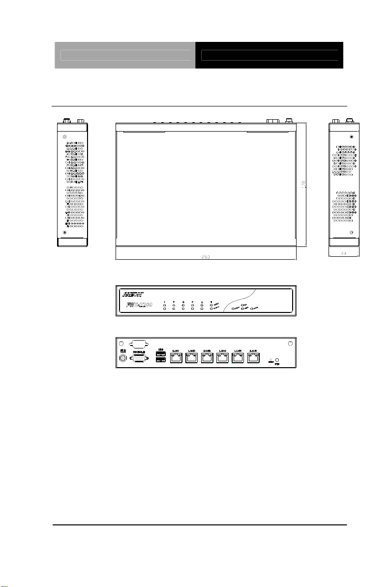
10.24”(W) x 7.01”(D) x 1.73”(H) (260mm x
178mm x 44mm)
29W
®
Intel
Atom™ D525 + ICH8M
®
Intel
Atom™ D525 integrated GMA 3150
graphic engine
2048x1536
VGA internal box header
COM x 2 (Internal pin header x 1):
COM1: RS-232
COM2: RS-232 (Box Header)
Keyboard & Mouse
USB
Reserved pin header
USB2.0 x 4: Dual Type-
connector on the
front panel x 2, Pin header x 2 (Internal)
Environment
o
32
Operating
F~104oF (0oC ~40oC)
Chapter 1 General Information 1- 5
Page 13

Network Appliance FWS-2200
Temperature
o
-4
S
torage
F~104oF (-20oC ~60oC)
Temperature
Operating Humidity
Storage Humidity
Vibration
Shock
10%~80% relative humidity,
non-condensing
10%~80% @ 40
o
C, non-condensing
0.5g rms/5~500Hz/ operation (2.5” HDD)
1.5g rms/5~500Hz/ non-operation
10G peak acceleration (11m sec.
duration), operation
20G peak acceleration (11m sec.
duration), non operation
Chapter 1 General Information 1- 6
Page 14
Network Appliance FWS-2200
1.4 General System Information
Chapter 1 General Information 1- 7
Page 15

Network Appliance FWS-2200
Installation
Chapter
2
Quick
Guide
Chapter 2 Quick Installation Guide 2-1
Page 16

Network Appliance FWS-2200
2.1 Safety Precautions
The installation is intended for technically qualified personnel who
have experience installing and configuring system boards.
The equipment can be installed in a restricted access location (RAL)
only.
A restricted access location is a site location for equipment where
the following criteria apply:
01. Access can only be gained by service persons or by users who
have been trained on the restrictions and the precautions for this
specific site.
02. Access is by means of at least one of the following, special tool,
lock and key, or other means of security, and is controlled by the
authority responsible for the location.
Safety Precautions:
Always completely disconnect the power cord
from your board whenever you are working on
it. Do not make connections while the power is
on, because a sudden rush of power can
damage sensitive electronic components.
Always ground yourself to remove any static
charge before touching the board. Modern
electronic devices are very sensitive to static
electric charges. Use a grounding wrist strap at
all times. Place all electronic components on a
static-dissipative surface or in a static-shielded
bag when they are not in the chassis
Chapter 2 Quick Installation Guide 2-2
Page 17
Network Appliance FWS-2200
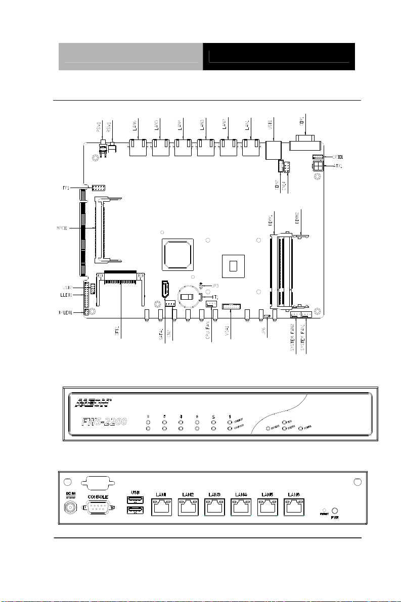
2.2 Location of Connectors of Main Board
LEDs on Front Panel of FWS-2200
Connectors on Rear Panel of FWS-2200
Chapter 2 Quick Installation Guide 2-3
Page 18
Network Appliance FWS-2200
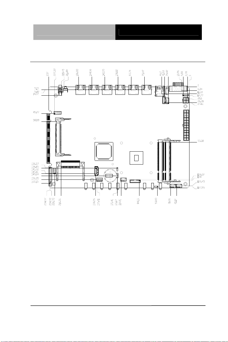
2.3 Mechanical Drawing of Main Board
Chapter 2 Quick Installation Guide 2-4
Page 19

Network Appliance FWS-2200
2.4 List of Jumpers
The board has a number of jumpers that allow you to configure your
system to suit your application.
The table below shows the function of each of the board's jumpers:
Label Function
JP3 CMOS Setting Selection
JP6 Auto PWRBTN Selection
2.5 List of Connectors
The board has a number of connectors that allow you to configure
your system to suit your application. The table below shows the
function of each board's connectors:
Label Function
SO-DIMM1 DDR3 SOCKET
SO-DIMM2 DDR3 SOCKET
ATX1 4P ATX POWER SUPPLY INP UT
CN6 3P FAN
CN14 KB/MS
COM1 COM PORT
COM2 COM PORT
VGA1 Analog Display
USB1 USB 2.0 *2
USB2 USB 2.0 *2
FP1 Front Panel Pin Header
Chapter 2 Quick Installation Guide 2-5
Page 20

Network Appliance FWS-2200
MPCI1 Mini PCI Slot
SATA1 SATA INTERFACE
CN2 SATA POWER
SYSFAN1 4-PIN Fan Connector
SYSFAN2 4-PIN Fan Connector
CPUFAN1 4-PIN Fan Connector
GPIO1 Digital I/O
CFD1 CF-SATA CARD SOCKET
LLED1 LAN LED Pin Header
BPLED1 Bypass LED Pin Header
PSW1 Power On/Off Switch
RSW1 Software Programmable Button
Chapter 2 Quick Installation Guide 2-6
Page 21
Network Appliance FWS-2200
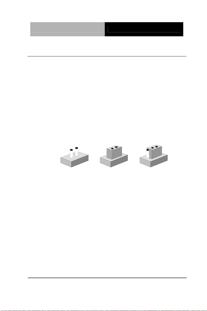
2.6 Setting Jumpers
You configure your card to match the needs of your application by
setting jumpers. A jumper is the simplest kind of electric switch. It
consists of two metal pins and a small metal clip (often protected by
a plastic cover) that slides over the pins to connect them. To “close”
a jumper you connect the pins with the clip.
To “open” a jumper you remove the clip. Sometimes a jumper will
have three pins, labeled 1, 2 and 3. In this case you would connect
either pins 1 and 2 or 2 and 3.
3
2
1
Open Closed Closed 2-3
A pair of needle-nose pliers may be helpful when working with
jumpers.
If you have any doubts about the best hardware configuration for
your application, contact your local distributor or sales
representative before you make any change.
Generally, you simply need a standard cable to make most
connections.
Chapter 2 Quick Installation Guide 2-7
Page 22

Network Appliance FWS-2200
2.7 CMOS Setting Selection (JP3)
JP3 Function
1-2 Normal (Default)
2-3 Clear CMOS
2.8 Auto PWRBTN Selection (JP6)
JP6 Function
1-2 Don’t use Auto PWRBTN (Default)
2-3 Use Auto PWRBTN
2.9 4-pin ATX Power Connector (CN9)
Pin Signal Pin Signal
1 GND 2 GND
3 +12V 4 +12V
2.10 Front Panel Connector (FP1)
Pin Signal Pin Signal
1 Power On Button (-) 2 Power On Button (+)
3 HDD LED(-) 4 HDD LED(+)
5 External Speaker (-) 6 External Speak er (+)
7 Power LED (-) 8 Power LED (+)
9 Reset Switch (-) 10 Reset Switch (+)
Chapter 2 Quick Installation Guide 2-8
Page 23

Network Appliance FWS-2200
2.11 Pin Header (USB2)
Pin Signal Pin Signal
1 +5V 2 GND
3 USBD1- 4 GND
5 USBD1+ 6 USBD2+
7 GND 8 USBD29 GND 10 +5V
11 CD-L
2.12 RS-232 Box Header (COM2)
Pin Signal Pin Signal
1 DCD 2 RXD
3 TXD 4 DTR
5 GND 6 DSR
7 RTS 8 CTS
9 RI 10 N.C
2.13 SATA Connector (SATA 1)
Pin Signal Pin Signal
1 GND 2 TXP
3 TXN 4 GND
5 RXN 6 RXP
7 GND
Chapter 2 Quick Installation Guide 2-9
Page 24

Network Appliance FWS-2200
2.14 CF-SATA Connector (CFD1)
Pin Signal Pin Signal
1 GND 26 GND
2 PDD3 27 PDD11
3 PDD4 28 PDD12
4 PDD5 29 PDD13
5 PDD6 30 PDD14
6 PDD7 31 PDD15
7 CS1 32 CS#3
8 GND 33 GND
9 GND 34 PDIOR
10 SATA_RXP 35 PDIOW
11 SATA_RXN 36 WE#
12 GND 37 INTRQ
13 VCC 38 VCC
14 GND 39 CSEL
15 SATA_TXN 40 CF-SATA_WE
16 SATA_TXP 41 RESET
17 GND 42 PDIORDY
18 PDA2 43 PDDREQ
19 PDA1 44 PDDACK
20 PDA0 45 DASP
21 PDD0 46 PDIAG
Chapter 2 Quick Installation Guide 2-10
Page 25

Network Appliance FWS-2200
22 PDD1 47 PDD8
23 PDD2 48 PDD9
24 NC 49 PDD10
25 GND 50 GND
2.15 Software Programmable Button (RSW1)
Pin Signal Pin Signal
1 SOFTWAREPRGM- 2 GND
Button status: I/O Space 0x4BA bit 0
2.16 Analog Display (VGA1)
Pin Signal Pin Signal
1 RED 2 CRTVCC
3 GREEN- 4 GND
5 BLUE 6 CRT_PLUG
7 NC 8 DDC_SDA
9 GND 10 HSYNC
11 GND 12 VSYNC
13 GND 14 DDC_SCL
15 GND 16 NC
Chapter 2 Quick Installation Guide 2-11
Page 26
Network Appliance FWS-2200
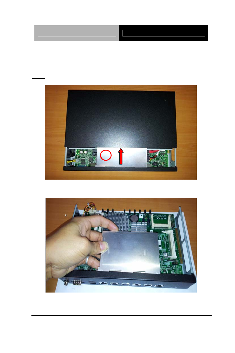
2.17 Installing the Hard Disk Drive
Step1: Unscrew the upper cover and isolate the cover from the Classis
Push and remove the upper cover until see the screw on the HDD
Note:
Box
Step2: Take out the Hard Disk Drive Case from the chassis
Chapter 2 Quick Installation Guide 2-12
Page 27
Network Appliance FWS-2200
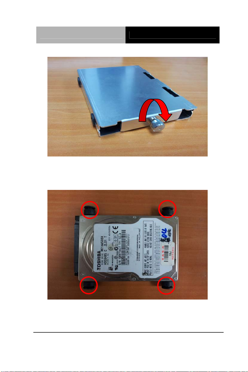
Step3: Turn the screw to open the HDD case
Step4: Fasten the four screws of the Hard DISK Drive Bracket
Chapter 2 Quick Installation Guide 2-13
Page 28
Network Appliance FWS-2200
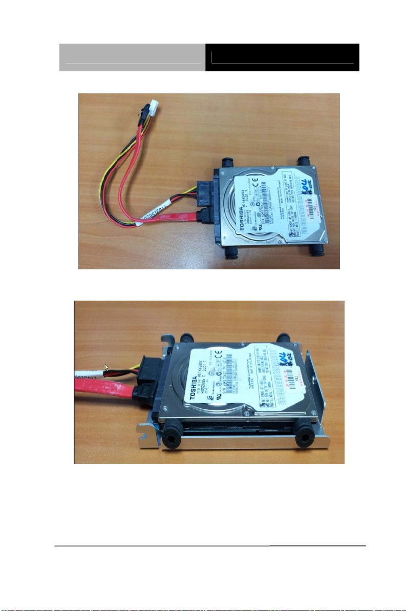
Step5: Plug the SATA cable & Power cable in the HDD
Step6: Put the HDD with cable onto the HDD Bracket
Chapter 2 Quick Installation Guide 2-14
Page 29
Network Appliance FWS-2200
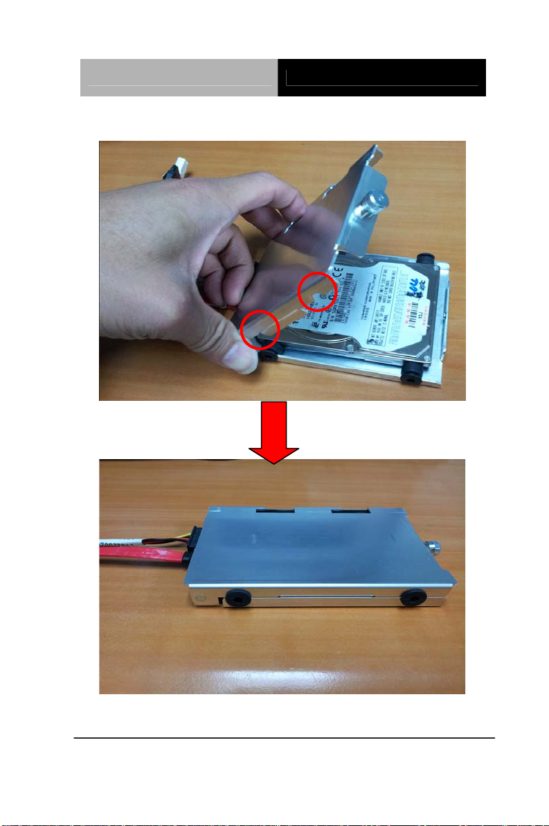
Step7: Close the upper bracket of the HDD case and make sure the rubber
feet are locked by the flutes on the brackets
Chapter 2 Quick Installation Guide 2-15
Page 30

Network Appliance FWS-2200
Step8: Fasten the screw conversely to lock the HDD
Step9: Plug the SATA cable & Power cable in the SATA socket & Power
socket on the main board
Chapter 2 Quick Installation Guide 2-16
Page 31

Network Appliance FWS-2200
Step10: Insert the HDD to the chassis horizontally and lock
the HDD case
Chapter 2 Quick Installation Guide 2-17
Page 32

Network Appliance FWS-2200
Step11: Close and screw the upper cover of the chassis
Chapter 2 Quick Installation Guide 2-18
Page 33

Network Appliance FWS-2200
Below Table for China RoHS Requirements
产品中有毒有害物质或元素名称及含量
AAEON Boxer/ Industrial System
有毒有害物质或元素
部件名称
印刷电路板
铅
(Pb)汞 (Hg)镉 (Cd)
六价铬
(Cr(VI))
多溴联苯
(PBB)
多溴二苯醚
(PBDE)
× ○ ○ ○ ○ ○
及其电子组件
外部信号
× ○ ○ ○ ○ ○
连接器及线材
外壳
中央处理器
× ○ ○ ○ ○ ○
× ○ ○ ○ ○ ○
与内存
硬盘
电源
O:表示该有毒有害物质在该部件所有均质材料中的含量均在
SJ/T 11363-2006 标准规定的限量要求以下。
X:表示该有毒有害物质至少在该部件的某一均质材料中的含量超出
SJ/T 11363-2006 标准规定的限量要求。
备注:
一、此产品所标示之环保使用期限,系指在一般正常使用状况下。
二、上述部件物质中央处理器、内存、硬盘、电源为选购品。
× ○ ○ ○ ○ ○
○ ○ ○ ○ ○
×
Chapter 2 Quick Installation Guide 2-19
Page 34

Network Appliance FWS-2200
Chapter
3
AMI
BIOS Setup
Chapter 3 AMI BIOS Setup 3-1
Page 35

Network Appliance FWS-2200
3.1 System Test and Initialization
These routines test and initialize board hardware. If the routines
encounter an error during the tests, you will either hear a few short
beeps or see an error message on the screen. There are two kinds
of errors: fatal and non-fatal. The system can usually continue the
boot up sequence with non-fatal errors.
System configuration verification
These routines check the current system configuration stored in the
CMOS memory and BIOS NVRAM. If system configuration is not
found or system configuration data error is detected, system will
load optimized default and re-boot with this default system
configuration automatically.
There are four situations in which you will need to setup system
configuration:
1. You are starting your system for the first time
2. You have changed the hardware attached to your system
3. The system configuration is reset by Clear-CMOS jumper
4. The CMOS memory has lost power and the configuration
information has been erased.
The FWS-2200 CMOS memory has an integral lithium battery
backup for data retention. However, you will need to replace the
complete unit when it finally runs down.
Chapter 3 AMI BIOS Setup 3-2
Page 36

Network Appliance FWS-2200
3.2 AMI BIOS Setup
AMI BIOS ROM has a built-in Setup program that allows users to
modify the basic system configuration. This type of information is
stored in battery-backed CMOS RAM and BIOS NVRAM so that it
retains the Setup information when the power is turned off.
Entering Setup
Power on the computer and press <Del>or <F2> immediately. This
will allow you to enter Setup.
Chapter 3 AMI BIOS Setup 3-3
Page 37

Network Appliance FWS-2200
Setup Menu
Main
Chapter 3 AMI BIOS Setup 3-4
Page 38

Network Appliance FWS-2200
Advanced
Chapter 3 AMI BIOS Setup 3-5
Page 39

Network Appliance FWS-2200
ACPI Settings
Options summary :
Suspend mode
Supend Disabled
S1 (CPU Stop Clock)
S3 (Suspend to RAM)
S1 & S3 (Auto) Default
Select the ACPI st ate used for System Suspend
Chapter 3 AMI BIOS Setup 3-6
Page 40

Network Appliance FWS-2200
CPU Configuration
Options summary :
Hyper-Threading
Disabled
Enabled Default
En/Disable Intel Hyper-Threading Technology.
Chapter 3 AMI BIOS Setup 3-7
Page 41

Network Appliance FWS-2200
IDE Configuration
Options summary :
ATA Or IDE
Configuration
Disabled
Compatible
Enhanced Default
Select ATA or IDE Configuration.
IDE Default Configure SATA As
AHCI
Select SATA Controller mode.
Chapter 3 AMI BIOS Setup 3-8
Page 42

Network Appliance FWS-2200
LAN Bypass Configuration
Options summary :
LAN1_2 Power ON
ByPass
PassTru Default
Select LAN1 / 2 operation mode when system is Power On.
ByPass LAN1_2 Power OFF
PassTru Default
Select LAN1 / 2 operation mode when system is Power Off.
ByPass LAN3_4 Power ON
PassTru Default
Select LAN3 / 4 operation mode when system is Power On.
Chapter 3 AMI BIOS Setup 3-9
Page 43

Network Appliance FWS-2200
LAN3_4 Power OFF
ByPass
PassTru Default
Select LAN3 / 4 operation mode when system is Power Off.
ByPass WDT
Reset Default
Select Watch Dog function as normal system reset or LAN ByPass.
LAN1_2 Default WDT BYPASS
SELECT
LAN3_4
LAN1_2 AND LAN3_4
Select which pair LAN ByPass control by WDT.
Chapter 3 AMI BIOS Setup 3-10
Page 44

Network Appliance FWS-2200
Intel IGD SWSCI OpRegion
Options summary :
DVMT Mode Select
Fixed Mode
DVMT Mode Default
Select DVMT Mode/Fixed Mode.
DVMT/FIXED Memory
128MB
256MB
Maximum Default
Select DVMT/FIXED Mode Memory size used by Internal Graphics
Device.
Chapter 3 AMI BIOS Setup 3-11
Page 45

Network Appliance FWS-2200
USB Configuration
Options summary :
Legacy USB Support
Enabled Default
Disabled
Auto
Enables BIOS Support for Legacy USB Support. When enabled, USB can
be functional in legacy environment like DOS.
AUTO option disables legacy support if no USB devices are connected
Chapter 3 AMI BIOS Setup 3-12
Page 46

Network Appliance FWS-2200
Super IO Configuration
Chapter 3 AMI BIOS Setup 3-13
Page 47

Network Appliance FWS-2200
Serial Port Configuration
Chapter 3 AMI BIOS Setup 3-14
Page 48

Network Appliance FWS-2200
Options summary :
Serial Port
Disabled
Enabled Default
Allows BIOS to En/Disable correspond serial port.
Change Settings
(Serial Port 1)
Auto Default
IO=3F8h; IRQ=4;
IO=3F8h; IRQ=3,4,5,6,7,10,11,12;
IO=2F8h;
IRQ=3,4,5,6,7,10,11,12;
IO=3E8h;
IRQ=3,4,5,6,7,10,11,12;
Chapter 3 AMI BIOS Setup 3-15
Page 49

Network Appliance FWS-2200
IO=2E8h; IRQ=3,4,5,6,7,10,11,12;
Allows BIOS to Select Serial Port resource.
Change Settings
(Serial Port 2)
Auto Default
IO=2F8h; IRQ=3;
IO=3F8h; IRQ=3,4,5,6,7,10,11,12;
IO=2F8h;
IRQ=3,4,5,6,7,10,11,12;
IO=3E8h;
IRQ=3,4,5,6,7,10,11,12;
IO=2E8h; IRQ=3,4,5,6,7,10,11,12;
Allows BIOS to Select Serial Port resource.
Chapter 3 AMI BIOS Setup 3-16
Page 50

Network Appliance FWS-2200
H/W Monitor
Chapter 3 AMI BIOS Setup 3-17
Page 51

Network Appliance FWS-2200
Smart Fan Mode Configuration
Options summary :
SYSFAN2
SYSFAN1
CPUFAN1 Mode
Manual Mode
Thermal Cruise Mode
SMART FAN III Mode Default
SYSFAN2/SYSFAN1/CPUFAN1 Mode Select
SYSFAN2
91 (Default)
SYSFAN1
CPUFAN1 PWM Value
Input expect PWM Output Value (Range:0 - 255)
Chapter 3 AMI BIOS Setup 3-18
Page 52

Network Appliance FWS-2200
SYSFAN2
AN1
SYSF
75 (Default)
CPUFAN1 Target
Temperature
Input SYSFAN2/SYSFAN1/CPUFAN1 Target Temperature (Range:0
-127)
SYSFAN2
2 (Default)
SYSFAN1
CPUFAN1 Tolerance
Input Tolerance of T arget Temperature (Range:0 -15)
SYSFAN2
255 (Default)
SYSFAN1
CPUFAN1 Max Output
SYSFAN2/SYSFAN1/CPUFAN1 PWM max output value (Range:0 -255)
SYSFAN2
14 (Default)
SYSFAN1
CPUFAN1 Output Step
SYSFAN2/SYSFAN1/CPUFAN1 output step value (Range:0 -255)
SYSFAN2
10 (Default)
SYSFAN1
CPUFAN1 Step down Time
SYSFAN2/SYSFAN1/CPUFAN1 step down time value,unit is 0.1,default
is 1 second (Range:0 -255)
Chapter 3 AMI BIOS Setup 3-19
Page 53

Network Appliance FWS-2200
SYSFAN2
AN1
SYSF
10 (Default)
CPUFAN1 Step up Time
SYSFAN2/SYSFAN1/CPUFAN1 step up time value,unit is 0.1,default is 1
second (Range:0 -255)
Serial Port Console Redirection
OOptions summary :
Console Redirection
Disabled
Enabled Default
Console Redirection Enable or Disable.
Chapter 3 AMI BIOS Setup 3-20
Page 54

Network Appliance FWS-2200
Console Redirection Settings
Options summary :
Terminal Type
VT100
VT100+
VT-UTF8
ANSI Default
Emulation:
ANSI: Extended ASCII char set.
VT100: ASCII char set.
VT100+: Extends VT100 to support color, functionkeys, etc.
VT-UTF8: Uses UTF8 encoding to map Unicode chars onto 1 or more
bytes.
9600 Bits per second
19200
Chapter 3 AMI BIOS Setup 3-21
Page 55

Network Appliance FWS-2200
38400
57600
115200 Default
Selects serial port transmission speed. The speed must be matched on
the other side. Long or noisy lines may require lower speeds.
7 Dat Bits
8 Default
Set Serial Port transmission data bits
Parity
None Default
Even
Odd
Mark
Space
A p arity bit ca n be sent with the data bits to detect some transmission
errors. Even: Parity bit is 0 if the num of 1’s in the data bits is even.
Odd: Partiy bit is 0 if num of 1’s in the data bits is odd.
Mark: Parity bit is always 1.
Space: Parity bit is always 0.
Mark and Sp ace Parity do not allow for error detection.
1 DefaultStop Bits
2
Chapter 3 AMI BIOS Setup 3-22
Page 56

Network Appliance FWS-2200
Stop bits indicate the end of a serial data packet. (A start bit indicates the
ning).
begin
The standard setting is 1 stop bit. Communication with slow devices may
require more than 1 stop bit.
None DefaultFlow Control
Hardware RTS/CTS
Flow control can prevent data loss from buffer overflow. When sending
data, if the receiving buffers are full, a ‘stop’ signal ca n be sent to stop the
data flow. Once the buffers are empty, a ‘start’ signal can be sent to
re-start the flow. Hardware flow control uses two wires to send start/stop
signals.
Disabled VT-UTF8 Combo Key
Support
Enabled Default
Enable VT-UTF8 Combination Key Support for ANSI/VT100 terminals.
Disabled DefaultRecorder Mode
Enabled
On this mode enabled only text will be send. This is to capture Terminal
data.
Disabled DefaultResolution 100x31
Enabled
Enables or disables extended terminal resolution.
80x24 DefaultLegacy OS Redirection
Resolution
80x25
On Legacy OS, the Number of Rows and Columns supported redirection.
Chapter 3 AMI BIOS Setup 3-23
Page 57

Network Appliance FWS-2200
Putty Keypad
VT100 Default
LINUX
XTERMR6
SCO
ESCN
VT400
Select FunctionKey and KeyPad on Putty.
Always Enable DefaultRedirection After BIOS
POST
BootLoader
The Settings spectify if BootLoader is selected than Legacy console
redirection is disabled before booting to Legacy OS. Default value is
Always Enable which means Legacy Console Redirection is enabled for
Legacy OS.
Chapter 3 AMI BIOS Setup 3-24
Page 58

Network Appliance FWS-2200
Chipset
Chapter 3 AMI BIOS Setup 3-25
Page 59

Network Appliance FWS-2200
North Bridge
Chapter 3 AMI BIOS Setup 3-26
Page 60

Network Appliance FWS-2200
OnChip VGA Config uration
Options summary :
Share Memory Size
Select Share Memory Size.
Disabled
1 MB
8 MB Default
Chapter 3 AMI BIOS Setup 3-27
Page 61

Network Appliance FWS-2200
South Bridge
Options summary :
Power Mode
ATX Default
AT
Select Power supply mode:
ATX: Normal ACPI support
AT: Suspend/Sleep disabled, and Always On when restoring from power
failure.
Disabled USB Function
Enabled Default
Enable or disable USB Function.
Chapter 3 AMI BIOS Setup 3-28
Page 62

Network Appliance FWS-2200
USB 2.0(EHCI) Support
Enabled Default
Disabled
Enable or disable USB 2.0 (EHCI) Support.
Restore on Power Loss
Power Off
Power On
Last State Default
Select power state when power is re-applied after a power failure.
STATUS LED CTRL
LED OFF Default
RED LED ON
RED LED BLINK
RED LED FAST
BLINK
GREEN LED ON
GREEN LED BLINK
GREEN LED F AST
BLINK
Select the Status LED default action.
Disabled Resume on PCIe Wake
Enabled Default
Enables or Disables resuming from PCIe wake message and WAKE#
signal.
Disabled Resume on PCI PME
Enabled Default
Enables or Disables resuming from PCI PME# signal.
Chapter 3 AMI BIOS Setup 3-29
Page 63

Network Appliance FWS-2200
Resume on Ring
Disabled
Enabled Default
Enables or Disables resuming from RI# signal.
Boot
Options summary :
Quiet Boot
Disabled
Enabled Default
En/Disable showing boot logo.
Disabled Default Launch I82574L PXE
OpROM
Enabled
En/Disable Boot Option for Legacy Network Devices
Chapter 3 AMI BIOS Setup 3-30
Page 64

Network Appliance FWS-2200
BBS Priorities
Chapter 3 AMI BIOS Setup 3-31
Page 65

Network Appliance FWS-2200
Security
Change User/Supervisor Password
You can install a Supervisor password, and if you install a
supervisor password, you can then install a user pa ssword. A user
password does not provide access to many of the features in the
Setup utility.
If you highlight these items and press Enter, a dialog box appears
which lets you enter a password. You can enter no more than six
letters or numbers. Press Enter after you have typed in the
password. A second dialog box asks you to retype the password
for confirmation. Press Enter after you have retyped it correctly.
The password is required at boot time, or when the user enters the
Chapter 3 AMI BIOS Setup 3-32
Page 66

Network Appliance FWS-2200
Setup utility.
Remov
ing the Password
Highlight this item and type in the current password. At the next
dialog box press Enter to disable password protection.
Exit
Save Changes and Reset
Reset the system after saving the changes. This is the suggested
method to exit BIOS setup menu that if you have modify any
settings.
Chapter 3 AMI BIOS Setup 3-33
Page 67

Network Appliance FWS-2200
Discard Changes and Reset
Reset system setup without saving any changes. It will continue
system booting without reset.
Restore Defaults
Restore/Load Default values for all the setup options.
Save as User Defaults
Save the changes done so far as User Defaults.
Restore User Defaults
Restore the User Defaults to all the setup options.
Chapter 3 AMI BIOS Setup 3-34
Page 68

Network Appliance FWS-2200
Chapter
4
Driver
Inst
Chapter 4 Driver Installation 4-1
allation
Page 69

Network Appliance FWS-2200
The FWS-2200 comes with an AutoRun CD-ROM that contains all
drivers and utilities that can help you to install the driver
automatically.
Insert the driver CD, the driver CD-title will auto start and show the
installation guide. If not, please follow the sequence below to install
the drivers.
Follow the sequence below to install the drivers:
Step 1 – Install Chipset Driver
Step 2 – Install VGA Driver
Step 3 – Install LAN Driver
Step 4 – Install AHCI Driver
Please read instructions below for further detailed installations.
Chapter 4 Driver Installation 4-2
Page 70

Network Appliance FWS-2200
4.1 Installation:
Insert the FWS-2200 CD-ROM into the CD-ROM drive and install
the drivers from Step 1 to Step 4 in order.
Step 1 – Install INF Driver
1. Click on the Step 1-Chipset folder and double click on
the infinst_autol.exe
2. Follow the instructions that the window shows
3. The system will help you install the driver automatically
Step 2 – Install VGA Driver
1. Click on the Step 2 –VGA folder and select the OS
folder your system is
2. Double click on .exe located in each OS folder
3. Follow the instructions that the window shows
4. The system will help you install the driver automatically
Step 3 – Install LAN Driver
1. Click on the Step 3 –LAN folder and select the OS
folder your system is
2. Double click on .exe file located in each OS folder
3. Follow the instructions that the window shows
4. The system will help you install the driver automatically
Step 4 – Install AHCI Driver
Please refer to Appendix D AHCI Setting
Chapter 4 Driver Installation 4-3
Page 71

Network Appliance FWS-2200
A
Programming the
W
atchdog Timer
Appendix
Appendix A Programming the Watchdog Timer A-1
Page 72

Network Appliance FWS-2200
A.1 Programming
FWS-2200 utilizes W83627DHG chipset as its watchdog timer
controller.
Below are the procedures to complete its configuration and the
AAEON intial watchdog timer program is also attached based on
which you can develop customized program to fit your application.
Configuring Sequence Description
There are th
Unlock W83627DHG
Select register of
watchdog timer
Enable the function of
the watchdog timer
Use the function of the
watchdog timer
Lock W83627DHG
ree steps to complete the configuration setup:
(1) Enter the W83627DHG config Mode
(2) Modify the data of configuration registers
Appendix A Programming the Watchdog Timer A-2
Page 73

Network Appliance FWS-2200
(3) Exit the W83627DHG config Mode. Undesired re sult may
occur if the config Mode is not exited normally.
(1) Enter the W83627DHG config Mode
To enter the W83627DHG config Mode, two special I/O write
operations are to be performed during Wait for Key state. To
ensure the initial state of the key-check logic, it is necessary to
perform two write operations to the Special Address port (2EH).
The different enter keys are provided to select configuration ports
(2Eh/2Fh) of the next step.
Address Port Data Port
87h,87h: 2Eh 2Fh
(2) Modify the Data of the Registers
All configuration registers can be accessed after entering the config
Mode. Before accessing a selected register, the content of Index
07h must be changed to the LDN to which the register belongs,
except some Global registers.
(3) Exit the W83627DHG config Mode
The exit key is provided to select configuration ports (2Eh/2Fh) of
the next step.
Address Port Data Port
0aah: 2Eh 2Fh
CR 30h. (Default 02h)
BIT READ/WRITE DESCRIPTION
7~3 Reserved.
2 R/W 0: GPIO6 is inactive. 1: GPIO6 is active.
Appendix A Programming the Watchdog Timer A-3
Page 74

Network Appliance FWS-2200
1 R/W 0: GPIO5 is inactive. 1: GPIO5 is active.
0 R/W
0: WDTO# and PLED are inactive.
1: WDTO# and PLED are inactive.
CR F5h. (WDTO# and KBC P20 Control Mode Register; Default
00h)
BIT READ/WRITE DESCRIPTION
7~5 Reserved.
1000 time faster in WDTO# count mode.
0: Disable.
4 R/W
3 R/W
2 R/W
1 R/W
Reserved.
0
1: Enable.
(If bit-3 is Second Mode, the count mode is 1/1000 Sec.)
(If bit-3 is Minute Mode, the count mode is 1/1000 Min.)
Select WDTO# count mode.
0: Second Mode.
1: Minute Mode.
Enable the rising edge of KBC reset (P20) to issue
time-out event.
0: Disable.
1: Enable.
Disable/ Enable the WDTO# output low pulse to the
KBRST# pin (PIN60)
0: Disable.
1: Enable.
CR F6h. (WDTO# Counter Register; Default 00h)
BIT READ/WRITE DESCRIPTION
Watch Dog Timer Time-out value. Writing a non-zero
value to this register causes the counter to load the
value to Watch Dog Counter and start counting down.
If bits 7 and 6 of CR F7h are set, any Mouse Interrupt or
7~0 R/W
Keyboard Interrupt event will also cause the reload of
previously-loaded non-zero value to Watch Dog Counter
and start counting down. Reading this resigter returns
current value in Watch Dog Counter instead of Watch
Dog Timer Time-out value.
00h: Time-out Disable
Appendix A Programming the Watchdog Timer A-4
Page 75

Network Appliance FWS-2200
01h: Time-out occurs after 1 second/minute
02h: Time-out occurs after 2 second/minutes
03h: Time-out occurs after 3 second/minutes
…………………………………………………..
FFh: Time-out occurs after 255 second/minutes
CR F7h. (WDTO# Control & Status Register; Default 00h)
BIT READ/WRITE DESCRIPTION
Mouse interrupt reset watch-dog timer enable
7 R/W
6 R/W
5 Write “1” Only
4
3~0 R/W
R/W
Write“0”Clear
0: Watchdog timer is not affected by mouse interrupt.
1: Watchdog timer is reset by mouse interrupt.
Keyboard interrupt reset watch-dog timer enable
0: Watchdog timer is not affected by keyboard interrupt.
1: Watchdog timer is reset by keyboardd interrupt.
Trigger WDTO# event. This bit is self-clearing.
WDTO# status bit
0: Watchdog timer is running.
1: Watchdog timer issue time-out event.
These bits select IRQ resource for WDTO#. (02h for
SMI# event.)
Appendix A Programming the Watchdog Timer A-5
Page 76

Network Appliance FWS-2200
A.2 W83627DHG Watchdog Timer Initial Program
LDN Register Bit Description
00h: Time-out Disable
01h: Time-out occurs after 1 minute only.
WDT
Timer
0x07 0xF6
value
WDT
Unit
************************************************************************************
0x07 0xF5 Bit3
#include <stdio.h>
#include <conio.h>
#define SIOIndex 0x2E //Modify for project support 2E/4E
#define SIOData 0x2F //Modify for project support 2F/4F
#define void AaeonWDTConfig(void);
#define void AaeonWDTEnable(Byte Timer, boolean Unit);
void Main(){
// Procedure : AaeonWDTConfig
// This procudure will enable the WDT counting.
AaeonWDTConfig (void);
// Procedure : AaeonWDTEnable
// (byte)Timer : Time of WDT timer.(0x00~0xFF)
// (boolean)Unit : Select time unit(0: second, 1: minute).
AaeonWDTEnable(Byte Timer, boolean Unit);
}
02h: Time-out occurs after 2 second/minutes
03h: Time-out occurs after 3 second/minutes
Bit
……………………….......................................
[7-0]
FFh: Time-out occurs after 255
second/minutes
(The deviation is approx 1 second.)
Select WDTO# count mode.
0: Second Mode.
1: Minute Mode.
Appendix A Programming the Watchdog Timer A-6
Page 77

Network Appliance FWS-2200
************************************************************************************
// Procedure : AaeonWDTConfig
void AaeonWDTConfig (void){
Byte val;
//Super I/O Entry Key
outportb(SIOIndex,0x87);
outportb(SIOIndex,0x87);
//Setting WDT Pin.
outportb(SIOIndex,0x2D);
val = inportb((SIOData);
outportb(SIOIndex,0x2D);
outportb(SIOData,val & 0xFE);
// Enable WatchDog function
outportb(SIOIndex,0x07);
outportb(SIOData,0x08);
outportb(SIOIndex,0x30);
outportb(SIOData, 0x01);
}
**********************************************************************************
**
Appendix A Programming the Watchdog Timer A-7
Page 78

Network Appliance FWS-2200
************************************************************************************
// Procedure :
void AaeonWDTEnable (Byte Timer, boolean Unit){
Byte val;
//Super I/O Entry Key
outportb(SIOIndex,0x87);
outportb(SIOIndex,0x87);
// Select Logic Device Number Register
outportb(SIOIndex,0x07);
outportb(SIOData,0x08);
// Setting WDT Operation Mode
outportb(SIOIndex,0xF5);
val = inportb((SIOData);
outportb(SIOIndex,0xF5);
outportb(SIOData, val | Unit << 3 );
// Setting WDT Counter
outportb(SIOIndex,0xF6);
outportb(SIOData,Timer);
}
************************************************************************************
Appendix A Programming the Watchdog Timer A-8
Page 79

Network Appliance FWS-2200
I/O Information
Appendix
B
Appendix B I/O Information B-1
Page 80

Network Appliance FWS-2200
B.1 I/O Address Map
Appendix B I/O Information B-2
Page 81

Network Appliance FWS-2200
Appendix B I/O Information B-3
Page 82

Network Appliance FWS-2200
B.2 Memory Address Map
Appendix B I/O Information B-4
Page 83

Network Appliance FWS-2200
B.3 IRQ Mapping Chart
Appendix B I/O Information B-5
Page 84

Network Appliance FWS-2200
Appendix B I/O Information B-6
Page 85

Network Appliance FWS-2200
Appendix B I/O Information B-7
Page 86

Network Appliance FWS-2200
B.4 DMA Channel Assignments
Appendix B I/O Information B-8
Page 87

Network Appliance FWS-2200
Standard Firewall
A ppendix
C
Plat
Appendix C Standard Firewall Platform Setting C-1
form Setting
Page 88

Network Appliance FWS-2200
C.1 Standard Firewall Platform Setting
Status LED Control Table.
LED Off
Red LED On
Red LED Blink
I/O 0x048E bit1 I/O 0x048E bit4 I/O 0x048F bit3
0 0 0
1 0 0
0 0 1
Red LED Fast
Blink
Green LED On
1 0 1
1 1 1
Green LED
Blink
1 1 0
Green LED
Fast Blink
0 1 1
LAN ByPass Config Table
I/O 0x048C
LAN1_2 Power On
ByPass Mode
LAN1_2 Power On
Pass Through Mode
LAN1_2 Power Off
ByPass Mode
LAN1_2 Power Off
Pass Through Mode
LAN3_4 Power On
Appendix C Standard Firewall Platform Setting C-2
bit6
X X 1 0
X X 0 0
X 1 X 0
X 0 X 0
X X 1 1
I/O 0x048C
bit7
I/O 0x048D
bit0
I/O 0x4B8
bit5
Page 89

Network Appliance FWS-2200
ByPass Mode
LAN3_4 Power On
Pass Through Mode
LAN3_4 Power Off
ByPass Mode
LAN3_4 Power Off
Pass Through Mode
WDT for
LAN1_2 ByPass
WDT for
LAN3_4 ByPass
WDT for system
Reset Mode
Note : "X" means that no affected.
X X 0 1
X 1 X 1
X 0 X 1
1 X X 0
1 X X 1
0 X X 0 or 1
Appendix C Standard Firewall Platform Setting C-3
Page 90

Network Appliance FWS-2200
C.2 Status LED Sample Code
#define LED_BASE_ADDR 0x48E
// LED Off
VOID LED_OFF()
{
UINT16 TEMP16;
TEMP16 = IoIn16(LED_BASE_ADDR) & 0xF7ED;
IoOut16(LED_BASE_ADDR, TEMP16);
}
// Red LED On
VOID RED_LED_ON()
{
UINT16 TEMP16;
TEMP16 = IoIn16(LED_BASE_ADDR) & 0xF7ED;
TEMP16 |= 0x0002;
IoOut16(LED_BASE_ADDR, TEMP16);
}
// Red LED Blink
VOID RED_LED_BLINK()
Appendix C Standard Firewall Platform Setting C-4
Page 91

Network Appliance FWS-2200
{
UINT16 TEMP16;
TEMP16 = IoIn16(LED_BASE_ADDR) & 0xF7ED;
TEMP16 |= 0x0800;
IoOut16(LED_BASE_ADDR, TEMP16);
}
// Red LED Fast Blink
VOID RED_LED_FBLINK()
{
UINT16 TEMP16;
TEMP16 = IoIn16(LED_BASE_ADDR) & 0xF7ED;
TEMP16 |= 0x0802;
IoOut16(LED_BASE_ADDR, TEMP16);
}
// Green LED On
VOID GREEN_LED_ON()
{
UINT16 TEMP16;
TEMP16 = IoIn16(LED_BASE_ADDR) & 0xF7ED;
TEMP16 |= 0x0812;
Appendix C Standard Firewall Platform Setting C-5
Page 92

Network Appliance FWS-2200
IoOut16(LED_BASE_ADDR, TEMP16);
}
// Green LED Blink
VOID GREEN_LED_BLINK()
{
UINT16 TEMP16;
TEMP16 = IoIn16(LED_BASE_ADDR) & 0xF7ED;
TEMP16 |= 0x0012;
IoOut16(LED_BASE_ADDR, TEMP16);
}
// Green LED Fast Blink
VOID GREEN_LED_FBLINK()
{
UINT16 TEMP16;
TEMP16 = IoIn16(LED_BASE_ADDR) & 0xF7ED;
TEMP16 |= 0x0810;
IoOut16(LED_BASE_ADDR, TEMP16);
}
Appendix C Standard Firewall Platform Setting C-6
Page 93

Network Appliance FWS-2200
C.3 LAN Bypass Mode Sample Code
#define LANBP_BASE_ADDR 0x48C
#define PAIR_SEL_BASE_ADDR 0x4B8
/*
Select LAN Pair I or II
PAIR_NUM = 0x00 - PA IR I
0x01 - PAIR II
*/
VOID SEL_PAIR(
IN UINT8 PAIR_NUM;
)
{
UINT8 TEMP8;
PAIR_NUM = PAIR_NUM << 5;
TEMP8 = IoIn8(PAIR_SEL_BASE_ADDR) & 0xDF;
TEMP8 |= PAIR_NUM;
IoOut8(PAIR_SEL_BASE_ADDR, TEMP8);
}
/*
Execute LAN ByPass Settings
Appendix C Standard Firewall Platform Setting C-7
Page 94

Network Appliance FWS-2200
*/
VOID EXE_SET()
{
UINT8 TEMP8;
TEMP8 = IoIn8(LANBP_BASE_ADDR + 3) | 0x10;
IoOut8(LANBP_BASE_ADDR + 3, TEMP8);
Sleep(500);
IoOut8(LANBP_BASE_ADDR + 3, TEMP8 & 0xEF);
}
/*
LAN1 & 2 Power On ByPass Mode Set
BP_MODE = 0x00 - Pass Through Mode
= 0x01 - By Pass Mode
*/
VOID LAN12_PWRON_BP()
{
UINT8 TEMP8;
SEL_PAIR(0x00) ; // Select Pair I
TEMP8 = IoIn8(LANBP_BASE_ADDR + 1) & 0xFE;
TEMP8 |= BP_MODE;
Appendix C Standard Firewall Platform Setting C-8
Page 95

Network Appliance FWS-2200
IoOut8(LANBP_BASE_ADDR + 1, TEMP8);
EXE_SET(); // Execute Set
}
/*
LAN1 & 2 Power Off ByPass Mode Set
BP_MODE = 0x00 - Pass Through Mode
= 0x01 - By Pass Mode
*/
VOID LAN12_PWROFF_BP()
{
UINT8 TEMP8;
SEL_PAIR(0x00) ; // Select Pair I
TEMP8 = IoIn8(LANBP_BASE_ADDR) & 0x7F;
TEMP8 |= BP_MODE << 7;
IoOut8(LANBP_BASE_ADDR, TEMP8);
EXE_SET(); // Execute Set
}
/*
Appendix C Standard Firewall Platform Setting C-9
Page 96

Network Appliance FWS-2200
LAN3 & 4 Power On ByPass Mode Set
BP_MODE = 0x00 - Pass Through Mode
= 0x01 - By Pass Mode
*/
VOID LAN34_PWRON_BP()
{
UINT8 TEMP8;
SEL_PAIR(0x01) ; // Select Pair II
TEMP8 = IoIn8(LANBP_BASE_ADDR + 1) & 0xFE;
TEMP8 |= BP_MODE;
IoOut8(LANBP_BASE_ADDR + 1, TEMP8);
EXE_SET(); // Execute Set
}
/*
LAN3 & 4 Power Off ByPass Mode Set
BP_MODE = 0x00 - Pass Through Mode
= 0x01 - By Pass Mode
*/
VOID LAN34_PWROFF_BP()
{
UINT8 TEMP8;
Appendix C Standard Firewall Platform Setting C-10
Page 97

Network Appliance FWS-2200
SEL_PAIR(0x01) ; // Select Pair II
TEMP8 = IoIn8(LANBP_BASE_ADDR) & 0x7F;
TEMP8 |= BP_MODE << 7;
IoOut8(LANBP_BASE_ADDR, TEMP8);
EXE_SET(); // Execute Set
}
/*
Set Watch Dog as LAN1 & 2 By Pass mode
*/
VOID WDT_LAN12_BP()
{
UINT8 TEMP8;
SEL_PAIR(0x00) ; // Select Pair I
TEMP8 = IoIn8(LANBP_BASE_ADDR) | 0x40;
IoOut8(LANBP_BASE_ADDR, TEMP8);
EXE_SET(); // Execute Set
}
Appendix C Standard Firewall Platform Setting C-11
Page 98

Network Appliance FWS-2200
/*
Set Watch Dog as LAN3 & 4 By Pass mode
*/
VOID WDT_LAN34_BP()
{
UINT8 TEMP8;
SEL_PAIR(0x01) ; // Select Pair II
TEMP8 = IoIn8(LANBP_BASE_ADDR) | 0x40;
IoOut8(LANBP_BASE_ADDR, TEMP8);
EXE_SET(); // Execute Set
}
/*
Set Watch Dog as system reset mode
*/
VOID WDT_RESET()
{
UINT8 TEMP8;
SEL_PAIR(0x00) ; // Select Pair I
TEMP8 = IoIn8(LANBP_BASE_ADDR) & 0xBF;
IoOut8(LANBP_BASE_ADDR, TEMP8);
Appendix C Standard Firewall Platform Setting C-12
Page 99

Network Appliance FWS-2200
SEL_PAIR(0x00) ; // Select Pair II
IoOut8(LANBP_BASE_ADDR, TEMP8);
EXE_SET(); // Execute Set
}
Appendix C Standard Firewall Platform Setting C-13
Page 100

Network Appliance FWS-2200
C.4 Console Redirection
Console redirection allows you to maintain a system from a remote
location by re-directing keyboard input and text output through the
serial port. This section will tell you how to use the console
redirection.
1. Please insert consol e cable betwee n on FWS-2200 a nd remote
client system.
2. Setup BIOS in FWS-2200
BIOS >> Advanced >> Serial Port Console Re direction >>
Console Redirection: Enabled (Default)
Enabled Attempt to redirect console via COM port
Disabled Console redirection function
BIOS >> Advanced >> Serial Port Console Redirection >> Serial
Redirection Settings >> Bits per second: 115200 (Default)
3. Configure Console redirection on client system. This example is
for Windows platform.
Step1 - Click the Start button, point to programs >> Accesso ries
>> Communication, and click Hyper Terminal
Step2 - Enter any name for the new connection and select any
icon
Appendix C Standard Firewall Platform Setting C-14
 Loading...