

Page 1
EAP100
V 2 .10
Page 2

Quick Installation Guide
E A P 1 0 0 E n t e r p r i s e A c c e s s P o i n t E N G L I S H
Copyright N otic e
This document is protected by USA copyright laws and other laws. B esides, the
document is the property of 4 I P N E T, I N C . Y ou may not copy, reproduce, distribute,
publish, display, perf orm, or modif y any part of this publication in any f orm or by any
means without prior written permission f rom 4 I P N E T, I N C . Y ou may not alter or remov e any
copyright or other notice f rom copies of the content. All other brand and product names
are claimed or registered mark s of their respectiv e companies or organiz ations.
All rights reserv ed.
To download up-to-date v ersion, please v isit www.4 ipnet.com.
Copyright © 4IPNET, INC. All rights reserved.
Page 3

Quick Installation Guide
E A P 1 0 0 E n t e r p r i s e A c c e s s P o i n t E N G L I S H
Preface Pack ag e C o n t en t s
4ipnet EAP100 is a high-end Access Point (AP) with
the best price/ performance for business and
industrial applications and is compliant with the
latest industrial wireless security standards that are
required in the tightly secured enterprise network
environments. Its Wireless Distribution System
(WDS) feature allows for flexible extension of
wireless coverage. The dual-PoE LAN ports, LAN1
and LAN2, can receive Power over Ethernet (PoE)
and is capable of providing backups between each
other with its failover function. This provides
EAP100 with reliable connectivity. Its metal case is
IP50 anti-dust compliant, which means that EAP100
is well suited to WLAN deployment in industrial
environments.
1. EAP100 x 1
2. Quick Installation Guide x 1
3. CD-ROM x 1
4. Console Cable x 1
5. Ethernet Cable x 1
6. Power Adapter (DC 12V) x 1
7. 5dBi Antenna x 2
8. Mounting Kit x 1
9. Ground Cable x 1
It is recommended to keep the original
packing material for possible future shipment
when repair or maintenance is required. Any
returned product should be packed in its
original packaging to prevent damage during
delivery.
This Quick Installation Guide provides instructions
and reference materials for getting started with
4ipnet EAP100.
Copyright © 4IPNET, INC. All rights reserved.
1
Page 4
Quick Installation Guide
System Overview
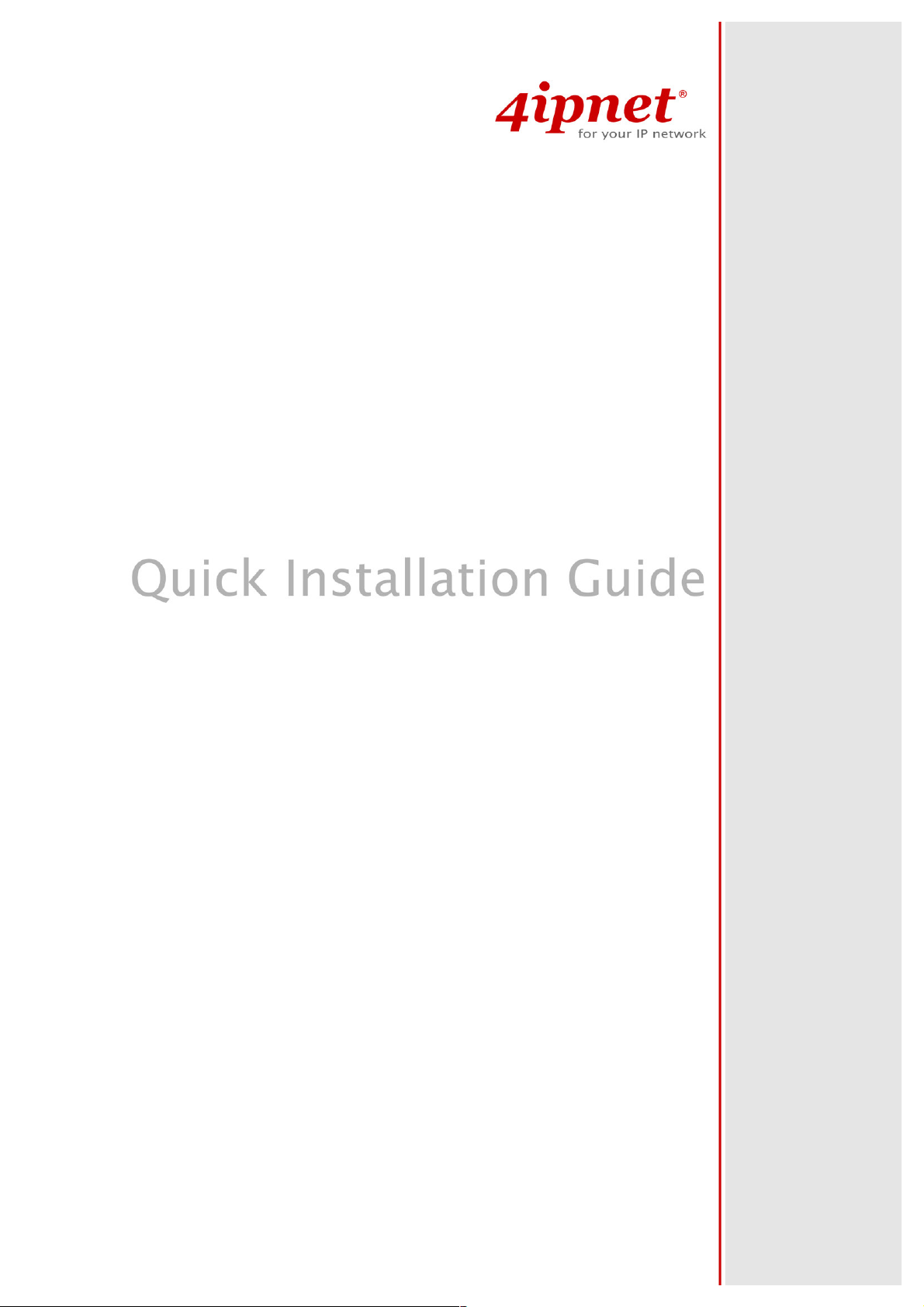
Front Panel
E A P 1 0 0 E n t e r p r i s e A c c e s s P o i n t E N G L I S H
Figure 1 EAP100 Front Panel
POWER SOCKET
RESET Button
LAN 1 / LAN 2
CONSOLE
Attach the power adapter here.
Press and hold the button for more than 10 seconds but no more than 30
seconds to restart the system. Hold the button for more than 30 seconds to
reset the device to factory defaults.
The LAN ports are for connecting to wired networks.
Attach the serial cable here. The administrator may also obtain IP address
information of Ethernet ports from the console port.
Copyright © 4IPNET, INC. All rights reserved.
2
Page 5
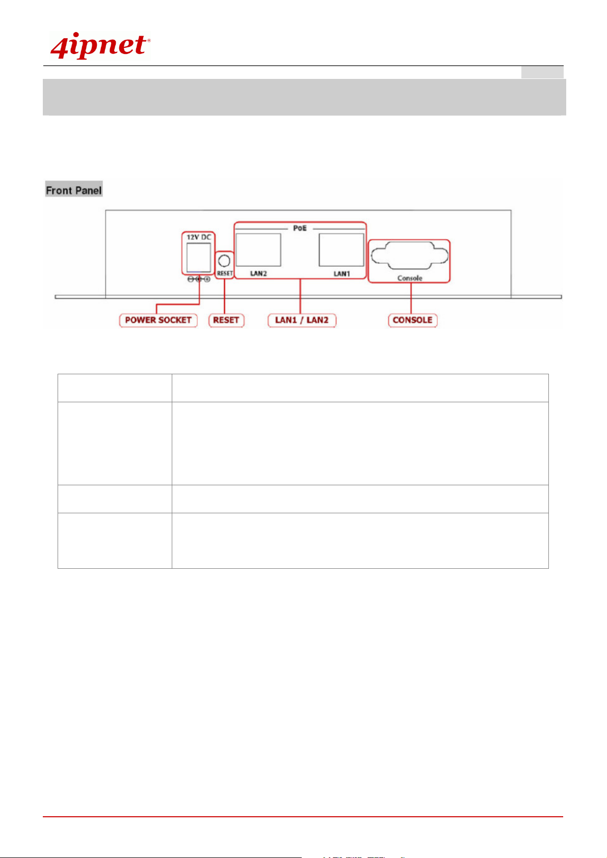
Rear Panel
Quick Installation Guide
E A P 1 0 0 E n t e r p r i s e A c c e s s P o i n t E N G L I S H
Figure 2 EAP100 Rear Panel
Antenna Connector:
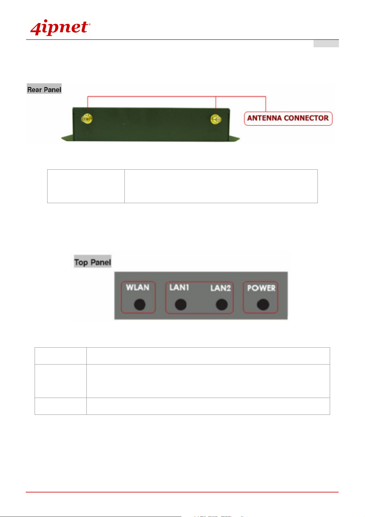
Top Panel – LED
Power
Attach the antennas here. EAP100 supports 1 RF interface and
2 SMA connectors for antenna connection.
Figure 3 EAP100 Top Panel
Green LED On indicates power on; OFF indicates power off.
LAN 1 / LAN 2
WLAN
OFF indicates no connection; ON indicates connection; CLINKING indicates
transmitting data.
Green LED ON indicates system ready.
Copyright © 4IPNET, INC. All rights reserved.
3
Page 6

Quick Installation Guide
E A P 1 0 0 E n t e r p r i s e A c c e s s P o i n t E N G L I S H
H a rd wa re I n sta l l a tio n
Please follow the steps mentioned below to install the hardware of EAP100:
1. Place the EAP100 at a best location.
The best location for EAP100 is usually at the center of your wireless network.
2. Connect EAP100 to your network device.
Connect one end of the Ethernet cable to the LAN1 or LAN2 port of EAP100 and the other end of the
cable to a switch, a router or a hub. EAP100 is then connected to your existing wired LAN network.
3. There are two ways to supply power over to EAP100.
Connect the DC power adapter to the EAP100 power socket.
(a)
Please only use the power adapter supplied with the EAP100 package. Using a different power
adapter may damage this system.
(b)
EAP100 LAN ports are capable of transmitting DC currents via its LAN1 or LAN2 PoE ports.
Connect an IEEE 802.3af-compliant PSE device, e.g. a PoE-switch, to the LAN1 or LAN2 port of
EAP100 with the Ethernet cable.
Now, the Hardware Installation is completed.
To double verify the wired connection between EAP100 and your switch/router/hub, please
check the LED status indication of these network devices.
Copyright © 4IPNET, INC. All rights reserved.
4
Page 7

Quick Installation Guide
E A P 1 0 0 E n t e r p r i s e A c c e s s P o i n t E N G L I S H
G ettin g Sta rted
4ipnet EAP100 supports web-based configuration. Upon the completion of hardware installation, EAP100 can
be configured through a PC by using its web browser such as Mozilla Firefox 2.0 or Internet Explorer version
6.0 and above.
The default values of LAN IP address and subnet mask of EAP100 are:
IP Address: 192.168.1.1
Subnet Mask: 255.255.255.0
Steps:
1. To access the web management interface, connect the administrator PC to the LAN1 or LAN2 port of
2. Launch the web browser on your PC by entering the IP address of EAP100 (http://192.168.1.1) at the
EAP100 via an Ethernet cable. Then, set a static IP address on the same subnet mask as EAP100 in
TCP/IP of your PC, such as the following example:
IP Address: 192.168.1.100
Subnet Mask: 255.255.255.0
address field, and then press Enter.
Figure 4 Example of entering EAP100's default IP Address into a web browser
Copyright © 4IPNET, INC. All rights reserved.
5
Page 8

Quick Installation Guide
E A P 1 0 0 E n t e r p r i s e A c c e s s P o i n t E N G L I S H
3. The following Administrator Login Page will then appear. Enter “admin” for both the User name and
Password fields, and then click OK to log in.
Figure 5 Administrator Login Page
4. After a successful login into EAP100, a System Overview page of web management interface will
appear, as depicted below.
Copyright © 4IPNET, INC. All rights reserved.
6
Page 9

Quick Installation Guide
E A P 1 0 0 E n t e r p r i s e A c c e s s P o i n t E N G L I S H
Figure 6 The Web Management Interface - System Overview Page
To logout, simply click on the Logout button at the upper right hand corner of the interface to return to the
Administrator Login Page.
Figure 7 Logout Prompt
Copyright © 4IPNET, INC. All rights reserved.
7
Page 10

Quick Installation Guide
C o mmo n Settin g s
Step 1. Change Administrator’s Password
E A P 1 0 0 E n t e r p r i s e A c c e s s P o i n t E N G L I S H
Figure 8 Change Password Screen
Click on the Utilities button, and then select the Admin Password tab.
Enter a new password with a length of up to 32 characters, and retype it in the Re-enter New
Password field.
Click Save to save the changes.
On each and every configuration page, you may
(a) Click Apply to allow the changes you made on the current page to take effect immediately
(Sometimes the system may require a restart after clicking Apply. When a restart message
Note:
appears, the system must be restarted for the settings to take effect.); or
(b) Click Save to save the changes, but you must reboot the system upon the completion of all
configuration settings for the changes to take effect. When clicking Save, the following
message will appear: “Some modifications have been saved and will take effect after
Reboot.”
Copyright © 4IPNET, INC. All rights reserved.
8
Page 11

Quick Installation Guide
Step 2. Configure AP (Access Point) Settings
E A P 1 0 0 E n t e r p r i s e A c c e s s P o i n t E N G L I S H
Figure 9 AP General Settings
Click on the Wireless button, and then select the General tab.
Determine the Band and Channel settings:
Select your preferred Band and Channel for you wireless connection. For example, select
802.11b+802.11g for the band and Auto for the channel.
Copyright © 4IPNET, INC. All rights reserved.
9
Page 12

Quick Installation Guide
E A P 1 0 0 E n t e r p r i s e A c c e s s P o i n t E N G L I S H
Step 3. Configure VAP (Virtual Access Point) Profile Settings
Figure 10 VAP Configuration Screen
EAP100 supports up to 8 virtual APs (VAPs). By default, only 1 VAP is enabled.
Configure VAP profile settings
(a) Select the VAP Config tab to configure the settings for each VAP.
(b) An administrator can enable or disable specific VAP from the drop-down list box of Profile Name.
Check VAP status
After finishing the above settings, the status of enabled Virtual APs shall be reflected on the Virtual AP
Overview page.
Copyright © 4IPNET, INC. All rights reserved.
10
Page 13

Quick Installation Guide
E A P 1 0 0 E n t e r p r i s e A c c e s s P o i n t E N G L I S H
Step 4. Configure WDS (Wireless Distribution System) Settings (Optional)
Figure 11 WDS Link Settings Page
To extend its wireless coverage, EAP100’s Repeaeter capability is capable of creating WDS links for
connecting to other WDS-capable APs (peer APs). EAP100 supports up to 4 WDS links. By default, all WDS
profiles are disabled.
Click on the Wireless button.
Select the Repeater tab.
Choose “WDS” as its Repeater Type:
a) Select preferred Security Type
b) Enter MAC Address of Remote AP (peer AP) and then Click Add
To configure peer AP(s):
After completing the WDS settings at this EAP100 (functioning as a “primary WDS station”), you
must also configure the settings of its peer AP(s).
If you use another EAP100 as the pear AP, simply repeat the above-mentioned steps with the MAC Address
of the primary WDS station for setting WDS Link parameters of the peer AP(s).
Copyright © 4IPNET, INC. All rights reserved.
11
Page 14

Quick Installation Guide
Step 4 (Cont). Check WDS Link Status
E A P 1 0 0 E n t e r p r i s e A c c e s s P o i n t E N G L I S H
Figure 12 WDS Link Status Page
Click on the Status button.
Select the Repeater tab.
Check the signal strength of WDS link(s)
Upon the completion of Step 4, there shall be RSSI displayed on the Repeater Information page. If the
RSSI is shown as N/A, check if the wiring is properly connected and please ensure the accurate
execution of Step 4 procedure as described above.
Congratulation!
Now, 4ipnet EAP100 is installed and configured successfully.
After EAP100's network configuration is completed, please remember to change the IP Address of
your PC Connection Properties back to its original settings in order to ensure that your PC functions
properly in its real network environments.
It is strongly recommended to make a backup copy of the configuration settings.
For further configuration and backup information, please refer to the User’s Manual.
P/N: V210 20 0 9 0 9 0 5
Copyright © 4IPNET, INC. All rights reserved.
12
 Loading...