

Page 1
3M™ Water Filtration Products
RO Membrane Cartridge Change-out Instructions (HFRO-500)
FOR ScaleGard
TM
HP Reverse Osmosis System
Explanation of Signal Word Consequences
WARNING Indicates a hazardous situation which, if not avoided, could result in death or serious injury.
CAUTION Indicates a hazardous situation which, if not avoided, could result in minor or moderate injury and/or property damage.
NOTICE Indicates hazardous situation which, if not avoided, may result in property damage.
WARNING
Read entire manual. Failure to follow all guide and rules could cause personal injury or property damage.
• Check with your local public works department for plumbing codes. You must follow their guidelines as you install the water ltration system.
• Your water ltration system will withstand up to 125 pounds per square inch (psi) water pressure.
To reduce the risk associated with choking:
• DO NOT allow children under 3 years of age to have access to small parts during the installation of this product.
To reduce the risk of serious injury associated with the potential ingestion of chemicals or contaminants:
• Do not use with water that is microbiologically unsafe or of unknown quality without adequate disinfection before or after the system.
• Flush RO Cartridge: Before use, you must ush the RO cartridge as specied in the installation instructions, and discard any water generated until ush is
complete. Failure to do so could cause serious injury from exposure to chemicals that can be extracted from the RO membrane during this initial ush.
• Sanitize and Flush Tank: Before use, you must sanitize and ush the hold tank as specied in the installation instructions. Sanitizing the hold tank minimizes
the risk for exposure to contaminants. Failure to ush the hold with water after sanitizing could cause serious injury from exposure to sanitizer present.
NOTICE
To reduce the risk associated with property damage due to water leakage or ooding:
• Read and follow Use Instructions provided with the original system prior to use of this replacement cartridge.
• The pre-lter and post-lter cartridges MUST be changed every 12 months, or sooner if the rated capacity is achieved or a noticeable reduction in ow
occurs.
• The RO membrane cartridge MUST be changed every 24 months, or sooner if a noticeable reduction in ow occurs.
• Failure to replace the lters and RO membrane cartridges at recommended intervals may lead to reduced lter performance and failure, causing property
damage from water leakage or ooding.
• Protect from freezing, remove all cartridges when temperatures are expected to drop below 40°F (4.4°C).
• DO NOT install systems in areas where ambient temperatures may go above 100°F (37.8°C).
• DO NOT install on hot water supply lines. The maximum operating water temperature of this lter system is 100°F (37.8°C).
• DO NOT install if water pressure exceeds 125 psi (862 kPa). Contact a plumbing professional if you are uncertain how to check your water pressure.
IMPORTANT NOTE:
The RO membrane cartridges have green labels and will only t into the head on the right side of the manifold (head has a green 3M label).
Shut Off Procedure:
RO membrane cartridge MUST be changed every 24 months or sooner. The pre-lter and post lter cartridges MUST be changed every 12 months or sooner.
1. Unplug system from the electrical outlet, which will shutoff feedwater to RO unit.
2. Conrm the operating pressure gauge (left) decreases to 0 psi. Note: Tank pressure gauge (right) will not decrease from the observed pressure.
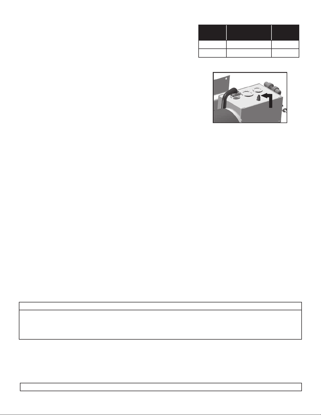
RO Membrane Cartridge (green label) Replacement:
1. Remove the reject tubing from the RO membrane cartridge. (See Figure 1).
2. Push and hold yellow tab to release RO membrane cartridge locking mechanism while simultaneously rotating RO membrane cartridge to the left.
3. Using both hands and holding the RO membrane cartridge from the bottom, rotate the RO membrane cartridge a quarter turn to the left and gently pull
down. NOTE: A small amount of water will drain from manifold as cartridge is removed.
4. Remove sanitary cap from new RO membrane cartridge. Ensure o-rings are seated into their grooves. Remove drain tting plug from new RO membrane
cartridge. Install with a quarter turn to the right until RO membrane cartridge comes to a complete stop. NOTE: RO membrane cartridges are keyed to t
in proper location only.
5. Insert new ow control into the elbow (included with new RO membrane cartridge). Install this sub assembly into the drain tting (cartridge bottom) See
Figure 3.
6. Connect reject line into elbow.
7. IMPORTANT: Complete System Start Up and Membrane Flushing procedure before system is brought back into use. See page 2.
Instructions continued on next page.
Page 2
System Start Up
1. Turn on the feedwater supply.
2. Open unit inlet shutoff valve.
3. Power the unit by plugging into electrical outlet.
4. Open Pre-Filter ush valve to vent air from system and ush for 10 gallons
(approximately 5 minutes).
5. Close Pre-Filter ush valve. The unit operating pressure gauge (left gauge) should
read between 110-120 psi. (See Operating Pressure instructions to adjust)
6. Complete blending valve adjustment procedure below. (See instructions below)
7. Close the blend line shut off valve. (Figure 2, #1)
8. Allow storage tank to ll until the RO system turns OFF on full tank (See chart). Tank operating
pressure for the 110-120VAC version is ON at 40 psi (276 kPa, 2.76 bar) and OFF at 60 psi (414
kPa, 4.14 bar) (right gauge). Tank operating pressure for the 220-240VAC is ON at 50 psi (345 kPa,
3.45 bar) and OFF at 70 psi (483 kPa, 4.83 bar).
9. Flush membrane by opening tank line sample valve and empty storage tank to drain. Operate the
system for at least 24 hours to ush the RO membrane. Discharge all water generated during the
ushing procedure to drain. Close the tank line sample valve after ushing is complete.
10. Sanitize the storage tank and RO system according to the storage tank and RO system
sanitizing instructions on page 3.
11. Open the blend line shut off valve (if product water blending is desired). Allow storage tank to rell. System is now ready for use.
Required (Sold Separately)
Part Number Pressure Volume
5598408 20 gallons (76 liters) 0.6 hours
5598409 40 gallons (151 liters) 1.2 hours
Figure 1 (Reset Button)
Reset
Button
Approximate
Time to Fill
Start Up Test Checklist
Close the tank shut off valve, open the tank line sample valve.
• Pump turns on √
• Water will ow thru the tank line sample valve and drain line √
Keep the tank shut off valve closed and close the tank line sample valve.
• Pump turns off √
• Water will stop owing from the drain line. √
• The operating pressure gauge will read 0 psi (0 kPa) at this point. √
• Tank pressure gauge will read 60 psi (414 kPa, 4.14 bar) for 110-120 VAC systems and 70 psi (483 kPa, 4.83 bar) for 220-240 VAC systems √
Open the tank line sample valve.
• Pump will turn on. √
• Tank pressure gauge will read 0 psi (0 kPa). √
• Permeate being rinsed for rst 25 seconds √
• After 30 seconds of operation, check production rate. √
• After 30 seconds of operation, check operating pressure. The operating pressure gauge should read 110-120 psi. √
• After 30 seconds of operation, check TDS reductions. √
Close the tank line sample valve and open the tank shut off valve. Allow storage tank to ll.
• Verify the tank pressure gauge increases to 60 psi (414 kPa, 4.14 bar) for 110-120 VAC systems and 70 psi (483 kPa, 4.83 bar) for 220-240 VAC systems √
• Verify the pump turns off and the drain line ow stops. √
Blending Valve Adjustment Instructions:
IMPORTANT NOTES:
• Typical TDS (Total Dissolved Solids) values for coffee are 80-200 ppm (parts per million) and occasionally lower for espresso, depending
upon taste preference. Typical TDS valves for steam and combi ovens are less than 50ppm.
• The blending valve should be set at start-up and checked periodically. This valve is a precision metering valve that has a lock nut.
• To set blending valve use TDS monitor set in the "out" position.
1. Open the blend line shut off valve.
2. Allow the unit to run for 2 minutes.
3. To adjust blending, rotate the blending valve to the left (counterclockwise) to increase the product water TDS and to the right (clockwise) to decrease the
product water TDS (See Figure 2 item #2 below). The blending valve should be opened intermittently a quarter turn at a time. Check the TDS after each
incremental adjustment and again two (2) minutes after the desired TDS value is reached. Re-adjust and check, as needed. (See Figure 2-item #2 below)
4. Lock the blending valve using the lock nut.
5. After product water TDS is set, it should be checked periodically during operation to conrm it is at the desired level.
IMPORTANT NOTE: The TDS Monitor is push-button operated and requires two (2) 357A batteries. (Included in TDS meter)
Page 3

Membrane Flushing Instructions:
WARNING:
Flush RO Membrane Cartridge: Before use this cartridge must be flushed as specified in the Installation Instructions. Discard any water
generated before the flush procedure is completed. Failure to do so could cause serious injury from exposure to chemicals that can be
extracted from the RO membrane during this initial flush.
1. Open the tank line sample valve.
2. Close the blend line shut off valve. (Figure 2, #1)
3. Operate the unit for 24 hours minimum to ush the RO membrane.
Discharge all water generated during the ushing procedure to drain.
4. Close the tank line sample valve.
5. Open the blend line shut off valve if required for the application.
6. Allow unit to operate and ll the storage tank.
Storage Tank and RO System Sanitizing Instructions:
Sanitizing the storage tank requires:
• Common household bleach (5.25% non-scented) or sanitizing agent
• Eye dropper or plastic oral syringe
a.) Unplug the unit from the electrical outlet.
b.) Connect a length of tubing to the tank line sample valve and route this line to drain.
c.) Open the tank line sample valve and empty the storage tank.
d.) Close the tank line sample valve
e.) Disconnect the 1/2" line from marked “Tank Outlet” to storage tank.
f.) Insert 15ml (0.5 ounces) of bleach or sanitizing agent into 1/2" line to storage tank.
g.) Reconnect the 1/2" line to storage tank.
h.) Plug the unit into the electrical outlet and operate the unit for 10 minutes.
i.) Unplug unit from the electrical outlet.
j.) Wait 4-5 hours.
k.) Open the tank line sample valve and empty the storage tank.
l.) Close tank line sample valve and remove drain tube.
m.) Plug the unit into the electrical outlet. Operate system until storage tank is full.
n.) Sanitizing is now complete.
o.) If there is any residual chlorine/bleach taste, drain storage tank completely a second time.
1 - blend line shutoff valve
2 - blending valve
Figure 2
2
1
Cartridge Installation
Figure 3 — Flow Control Installation
Remove RO Membrane
Cartridge Drain Plug
Insert RO Membrane
Cartridge into right
manifold head
Insert Flow Control Into
Elbow
Insert elbow into
RO Membrane Cartridge
drain tting
Insert reject line into
elbow.
Flow control installation is
now complete.
Page 4

To Attach Tubing
To Release Tubing
Push tubing straight in as far as it
will go
Tubing is secured in. Push in collet to release tubing. Pull tubing straight out.
Figure 4 (How to Use “Push-in” Connectors)
This product is outtted with a user friendly ‘Push In’ connector at the vent valve. Proper use of the connectors is shown in the gure below. It is most
important that the tubing selected for use with these connectors be of high quality, exact size and roundness, and with no surface nicks or scratches.
If it is necessary to cut the tubing, use a plastic tubing cutter or sharp razor knife. Make a clean square cut. Should a leak occur at a “Push-In”
connector, the cause is usually a problem with the tubing.
To Fix:
1. Relieve pressure 2. Release tubing 3. Cut off at least 1/4” from end
4. Reattach tubing 5. Conrm connection is leak free
Product Use:
Many factors beyond 3M Purication Inc.’s (3M’s) control and uniquely within user’s knowledge and control can affect the use and performance of a 3M product
in a particular application. User is solely responsible for evaluating the 3M product and determining whether it is t for a particular purpose and suitable for
user’s method of application.
Warranty, Limited Remedy, and Disclaimer:
3M warrants that this product will be free from defects in material and manufacture for the period of (1) year from the date of purchase. No warranty is given as
to the service life of any lter cartridge or membrane as it will vary with local water conditions and water consumption. 3M MAKES NO OTHER WARRANTIES
OR CONDITIONS, EXPRESS OR IMPLIED, INCLUDING, BUT NOT LIMITED TO, ANY IMPLIED WARRANTY OR CONDITION OF MERCHANTABILITY OR FITNESS
FOR A PARTICULAR PURPOSE OR ANY IMPLIED WARRANTY OR CONDITION ARISING OUT OF A COURSE OF DEALING, CUSTOM OR USAGE OF TRADE.
If the 3M product does not conform to this warranty, then the sole and exclusive remedy is, at 3M’s option, replacement of the 3M product or refund of the
purchase price.
Limitation of Liability:
Except where prohibited by law, 3M will not be liable for any loss or damage arising from the 3M product, whether direct, indirect, special, incidental or
consequential, regardless of the legal theory asserted, including warranty, contract, negligence or strict liability.
3M Purication Inc.
400 Research Parkway
Meriden, CT 06450, U.S.A.
Tel (866) 990-9785
(203) 237-55 41
Fax (203) 238-8977
www.3Mfoodservice.com
www.3Mpurication.com
3M and ScaleGard are trademarks of 3M Company.
© 2020 3M Company. All rights reserved.
34-8726-1663-5
 Loading...