

Page 1
Instructions for the following series products:
Sayine™ Multi-Span Wire Rope
Horizontal Lifeline
(See inside back page for specic model numbers.)
User Instruction Manual
Sayine™ Multi-span Wire Rope Horizontal Lifeline
This manual is intended to meet the Manufacturer’s Instructions requirement of applicable standards dened in
Section 1.2 and should be used as part of an employee training program as required by the identied agencies.
WARNING: This product is part of a fall protection system. The users must read and follow the
manufacturer’s instructions for each component of the system. These instructions must be provided to the
users of this equipment. The users must read and understand these instructions before using this equipment.
Manufacturer’s instructions must be followed for proper use and maintenance of this product. Alterations or
misuse of this product, or failure to follow instructions, may result in serious injury or death.
IMPORTANT: If you have questions on the use, care, or suitability of this equipment for your application,
contact 3M Fall Protection.
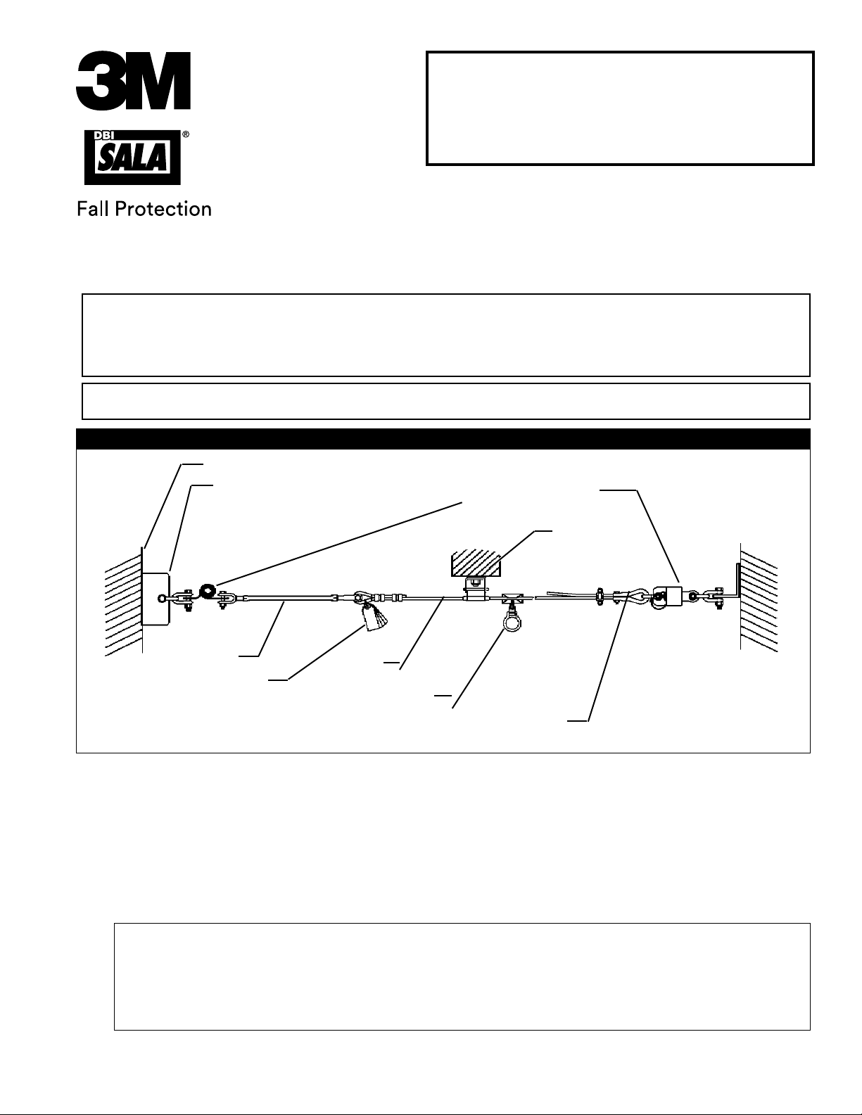
Figure 1 - Typical Sayine™ Multi-span Wire Rope Horizontal Lifeline System
Anchorage
Anchorage Connector
(Supplied by customer)
Zorbit HLL Energy
Absorber
Intermediate
Bracket
Turnbuckle
Labels
Cable
Sayink Sleeve
Thimble/Cable Clip
End Termination
1.0 APPLICATION
1.1 PURPOSE: The Sayine Multi-span Wire Rope Horizontal Lifeline System is designed for use as an anchoring
means for one or two personal fall arrest system (PFAS) or fall restraint system. Use the Sayine Horizontal
Lifeline (HLL) where horizontal mobility and fall protection is required. The Sayine Horizontal Lifeline may
not be used for fall protection of material or equipment.
1.2 LIMITATIONS: The following limits apply to the installation and use of Sayine Multi-span Wire Rope
Horizontal Lifeline System. Other limitations may apply:
IMPORTANT: The employer must ensure that each horizontal lifeline is designed, installed, and used under the
supervision of a qualied person; and is part of a complete personal fall arrest system that maintains a safety factor of
at least two. Reference OSHA 1010.140 (c) (11). See also OSHA 1926.502 (d)(8).
QUALIFIED PERSON: Qualied describes a person who, by possession of a recognized degree, certicate, or
professional standing, or who by extensive knowledge, training, and experience has successfully demonstrated the
ability to solve or resolve problems relating to the subject matter, the work, or the project. Reference OSHA 1910.140
(b). See also OSHA 1926.32 (m).
FORM NO: 5902167
REV: F
© 3M 2018
1
Page 2
A. HORIZONTAL LIFELINE SPAN: The maximum horizontal lifeline total length is 180 ft. (55 m) with a
Zorbit HLL energy absorber installed on each end of the system. See Figure 1. Systems that are more
than 30 ft. (9 m) in length must include an intermediate bracket for every 30 ft. span (9 m). The span
length must be reduced when clearance is limited. See section 3.3 for clearance information.
B. ANCHORAGES: The Sayine horizontal lifeline must be installed on anchorages that meet the
requirements specied in section 2.5.
C. SYSTEM CAPACITY: The maximum capacity of the Sayine horizontal lifeline is two persons. The
maximum weight of each person, including tools and clothing, is 310 lbs (141 kg).
D. CONNECTING SUBSYSTEM: Each person’s connecting subsystem must limit fall arrest forces to 900
lbs. (4 kN) or less. See section 2.6.
E. FREE FALL: Rig and use the personal fall arrest system such that the maximum potential free fall does
not exceed government regulatory and subsystem manufacturer’s requirements. The personal fall arrest
system must be rigged to limit free falls to six feet or less when using an energy absorbing lanyard, or
such that the SRL is overhead and without slack, according to OSHA requirements. See section 3.0 and
subsystem manufacturer’s instructions for more information.
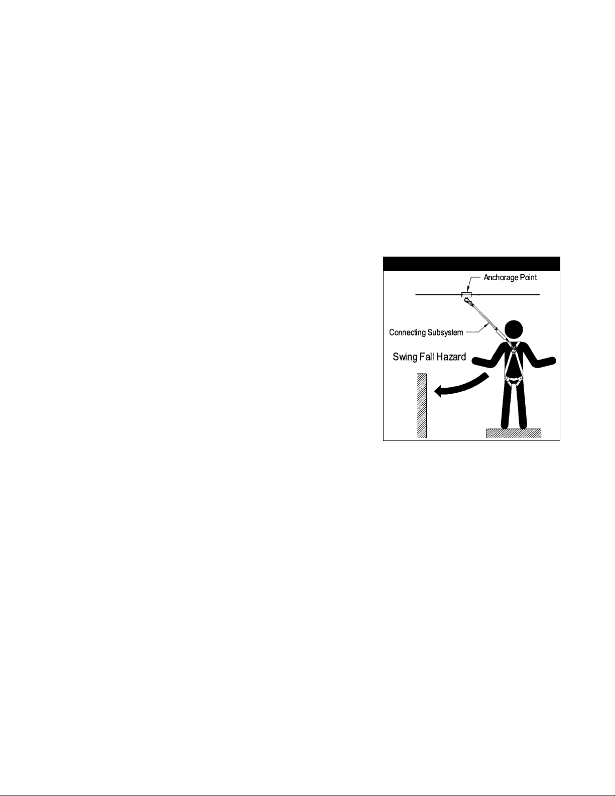
F. SWING FALLS: See Figure 2. Swing falls occur when the
anchorage point is not directly overhead. The force of striking an
object in a swing fall may cause serious injury or death. Minimize
swing falls by working as directly below the anchorage point as
possible. Do not permit a swing fall if injury could occur. Swing
falls will signicantly increase the clearance required when a self
retracting lifeline or other variable length connecting subsystem
is used. If a swing fall situation exists in your application, contact
3M Fall Protection before proceeding.
G. FALL CLEARANCE: There must be sufcient clearance below
the worker to arrest a fall before striking the lower level or
obstruction. See section 3.3 for required clearance information.
H. BODY SUPPORT: Sayine Multi-span Wire Rope Horizontal
Lifelines must only be used with personal fall arrest systems
incorporating a full body harness.
I. PHYSICAL AND ENVIRONMENTAL HAZARDS: Use of this equipment in areas with physical or
environmental hazards may require additional precautions to reduce the possibility of injury to the user
or damage to the equipment. Hazards may include, but are not limited to; heat, chemicals, corrosive
environments, high voltage power lines, gases, moving machinery, and sharp edges. Contact 3M Fall
Protection if you have questions about using this equipment where physical or environmental hazards
exist.
J. TRAINING: This equipment must be installed and used by persons trained in the correct application
and use of this equipment. See section 5.0.
Figure 2 - Swing Falls
1.3 APPLICABLE STANDARDS: Refer to national standards, including ANSI Z359.1-1992, and local, state, and
federal (OSHA 1910.66 and 1926.502) requirements for more information on personal fall arrest systems
and associated components.
2.0 SYSTEM REQUIREMENTS
2.0YSTEM REQUIREMENTS
2.1 PERSONAL FALL ARREST SYSTEM COMPONENTS: The Sayine horizontal lifeline must be used with 3M
Fall Protection approved components and subsystems. Non-approved components may be incompatible, and
could affect the safety and reliability of the complete system. Personal fall arrest components used with this
system must meet all applicable OSHA and ANSI requirements. A full body harness must be used with this
system. The connecting subsystem between the harness and horizontal lifeline must limit fall arrest forces to
900 lbs. or less.
2.2 COMPATIBILITY OF CONNECTORS: Connectors are considered to be compatible with connecting
elements when they have been designed to work together in such a way that their sizes and shapes do not
cause their gate mechanisms to inadvertently open regardless of how they become oriented. Contact 3M Fall
Protection if you have any questions about compatibility.
2
Page 3
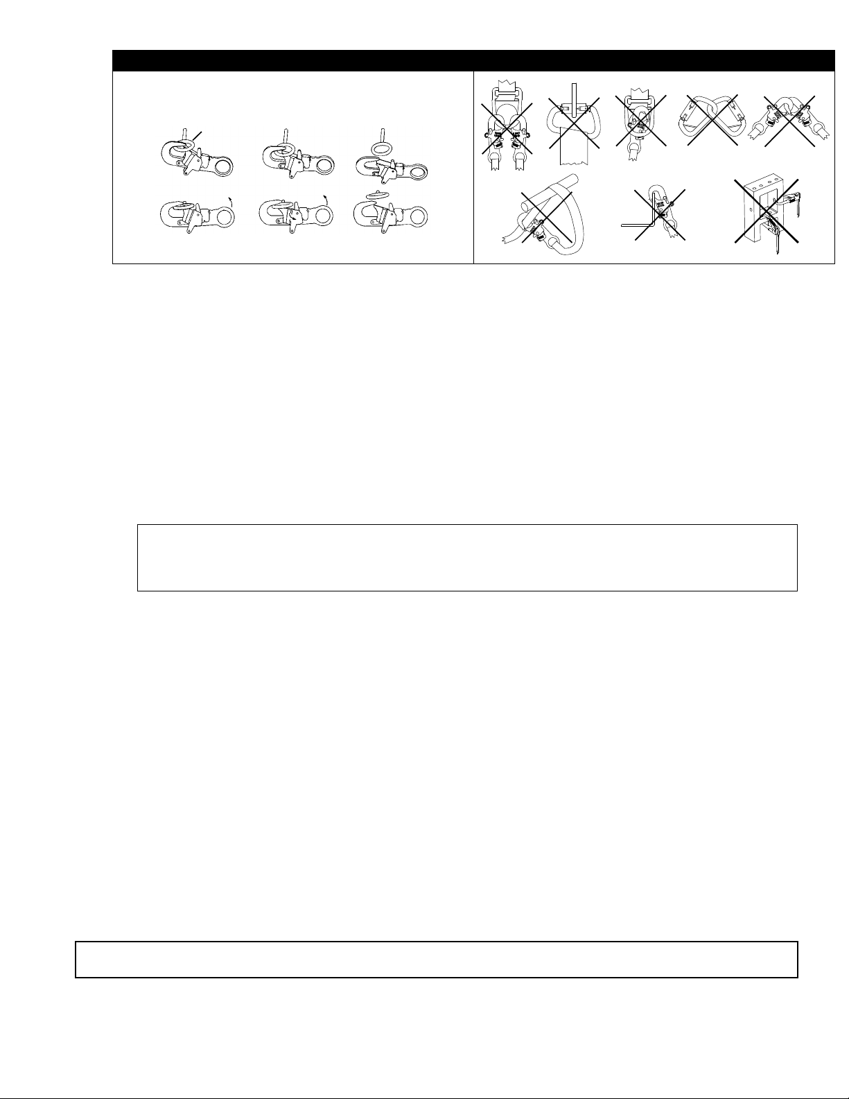
Figure 3 - Unintentional Disengagement Figure 4 - Inappropriate Connections
If the connecting element to which a snap hook (shown) or carabiner attaches
is undersized or irregular in shape, a situation could occur where the connecting
element applies a force to the gate of the snap hook or carabiner. This force may
cause the gate (of either a self-locking or a non-locking snap hook) to open,
allowing the snap hook or carabiner to disengage from the connecting point.
Small ring or other
non-compatibly
shaped element
A. B. C. D.
E. F. G.
Force is applied to the
Snap Hook.
The Gate presses against
the Connecting Ring.
The Gate opens allowing
the Snap Hook to slip off.
Connectors (hooks, carabiners, and D-rings) must be capable of supporting at least 5,000 lbs. (22kN).
Connectors must be compatible with the anchorage or other system components. Do not use equipment
that is not compatible. Non-compatible connectors may unintentionally disengage. See Figure 3. Connectors
must be compatible in size, shape, and strength. Self locking snap hooks and carabiners are required by
ANSI Z359.1 and OSHA.
2.3 MAKING CONNECTIONS: Only use self-locking snap hooks and carabiners with this equipment. Only use
connectors that are suitable to each application. Ensure all connections are compatible in size, shape and
strength. Do not use equipment that is not compatible. Ensure all connectors are fully closed and locked.
3M Fall Protection connectors (snap hooks and carabiners) are designed to be used only as specied in each
product’s user’s instructions. See Figure 4 for inappropriate connections. 3M Fall Protection snap hooks and
carabiners should not be connected:
A. To a D-ring to which another connector is attached.
B. In a manner that would result in a load on the gate.
NOTE: Large throat opening snap hooks should not be connected to standard size D-rings or similar
objects which will result in a load on the gate if the hook or D-ring twists or rotates. Large throat snap
hooks are designed for use on xed structural elements such as rebar or cross members that are not
shaped in a way that can capture the gate of the hook.
C. In a false engagement, where features that protrude from the snap hook or carabiner catch on the
anchor and without visual conrmation seems to be fully engaged to the anchor point.
D. To each other.
E. Directly to webbing or rope lanyard or tie-back (unless the manufacturer’s instructions for both the
lanyard and connector specically allow such a connection).
F. To any object which is shaped or dimensioned such that the snap hook or carabiner will not close and
lock, or that roll-out could occur.
G. n a manner that does not allow the connector to align properly while under load.
2.4 ANCHORAGE CONNECTORS: 3M Fall Protection does not supply anchorage fasteners. Connectors used to
attach the horizontal lifeline to end anchors must be compatible with the connection point. The connection
must be positive; and, with connecting elements, capable of sustaining a 5,000 lb. (22 kN) load without
failure.
The intermediate brackets require a 1/2-13 UNC bolt meeting SAE Grade 5 strength minimum. A at washer,
lock washer and a nut are also required. A locking nut may be used in place of the lock washer and plain
nut.
2.5 STRUCTURE LOAD: Structural anchorage points must be rigid, and capable of supporting at least 5,000
lbs. (22 kN) along the axis of the horizontal lifeline. Anchorages, including the intermediate brackets, must
also support at least 3,600 lbs. (16 kN) applied in all potential directions of fall arrest that are perpendicular
to the axis of the horizontal lifeline. See Figure 5.
WARNING: Anchorages must be rigid. Large deformations of the anchorage will affect system performance, and
may increase the required fall clearance below the system, which could result in serious injury or death.
2.6 CONNECTING SUBSYSTEM: The connecting subsystem is the portion of the personal fall arrest system
that is used to connect between the horizontal lifeline subsystem and harness fall arrest attachment
element. The connecting subsystem must limit forces applied to the horizontal lifeline to 900 lbs. (4 kN) or
less.
3
Page 4
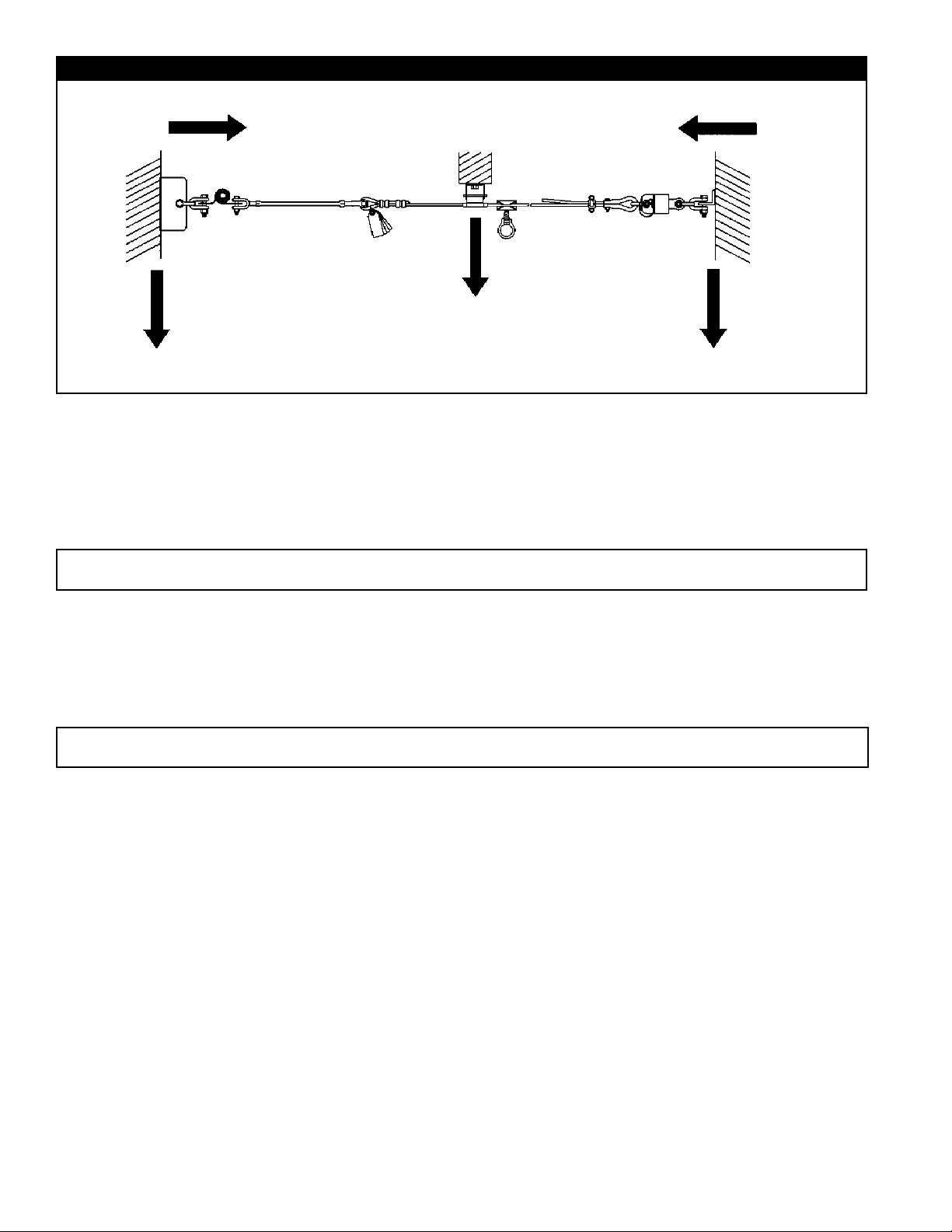
Figure 5 - Anchorage Strength
5,000 lbs Minimum
(22 kN Minimum)
3,600 lbs Minimum
(16 kN Minimum)
3,600 lbs (16 kN) Minimum
(in all potential direction of fall arrest applied loading)
5,000 lbs Minimum
(22 kN Minimum)
3,600 lbs Minimum
(16 kN Minimum)
3.0 INSTALLATION
3.1 Inspection
Upon receipt of the Sayine Horizontal Lifeline System, inspect all components and user equipment for
defects and/or damage. If any Sayine components or 3M Fall Protection equipment are found to be
damaged, defective, or missing, contact 3M Fall Protection immediately for replacements. Do not use any
defective or damaged parts in a Sayine Horizontal Lifeline System installation.
WARNING: Use of defective or damaged parts will hinder the performance of the Sayine system, potentially
causing serious injury or death in the event of a fall.
3.2 Safety
A separate means of fall protection must be utilized during the installation of a Sayine System. A separate
means of fall protection must be used when inspecting or servicing a Sayine System following a fall.
3M Fall Protection recommends the use of certied eye protection, steel toe boots and gloves be worn during
the installation of the horizontal lifeline system.
WARNING: Do not alter or intentionally misuse this equipment. Use caution when using this equipment around
moving machinery, electrical and chemical hazards, and sharp edges.
4
Page 5
3.3 SYSTEM INSTALLATION:
Figure 1 shows a typical horizontal lifeline system installation. When using an energy absorbing lanyard to connect
to the system, the anchorages must be located at a height above the working level which will limit the free fall to six feet. The
length of the lanyard must be considered when determining the height of the anchorages.
When using a self retracting lifeline (SRL) to connect to the system, the end anchorages must be located
above the user. The SRL, when fully retracted, must be above the harness attachment level. The horizontal
lifeline system should be positioned at a level that will minimize free fall while allowing ease of use.
The horizontal lifeline should be positioned near the work location to minimize swing fall hazards. The
connecting subsystem length should be kept as short as possible to reduce the potential free fall and
required clearance distance.
Both anchorages must be installed at approximately the same elevation, so that the horizontal lifeline
system is not sloped more than a 1:12 pitch (1 inch [3 cm] rise over a 12 inch [30 cm] run). The cable must
be in a straight line; no curves or turns are allowed in a Sayine Multi-span Lifeline installation.
The installation process consists of the following steps:
1. Determine the location of end anchors and intermediate brackets.
2. Determine the orientation of the intermediate brackets
3. Attach one end to its anchor point.
4. Install cable guides and Sayink sleeves onto the cable.
5. Assemble intermediate brackets into their anchor points.
6. Unthread turnbuckle(s)
7. Attach the other cable end to its anchor point and tension the cable
The steps are described in detail below:
Step 1. Determine the locations of the end anchorages and evaluate their strengths in accordance with
section 2.4. Determine the number of intermediate brackets necessary for your application. There
must be one intermediate bracket for every 30 feet (9 m) of cable for systems over 30 feet (9 m)
in length. Additional intermediate brackets (Part No. 7608001) may be purchased from 3M Fall
Protection. Use Figures 6 and 7 to determine the span length and evaluate the required clearance.
Figures 6 and 7 apply to one or two users connected to the system.
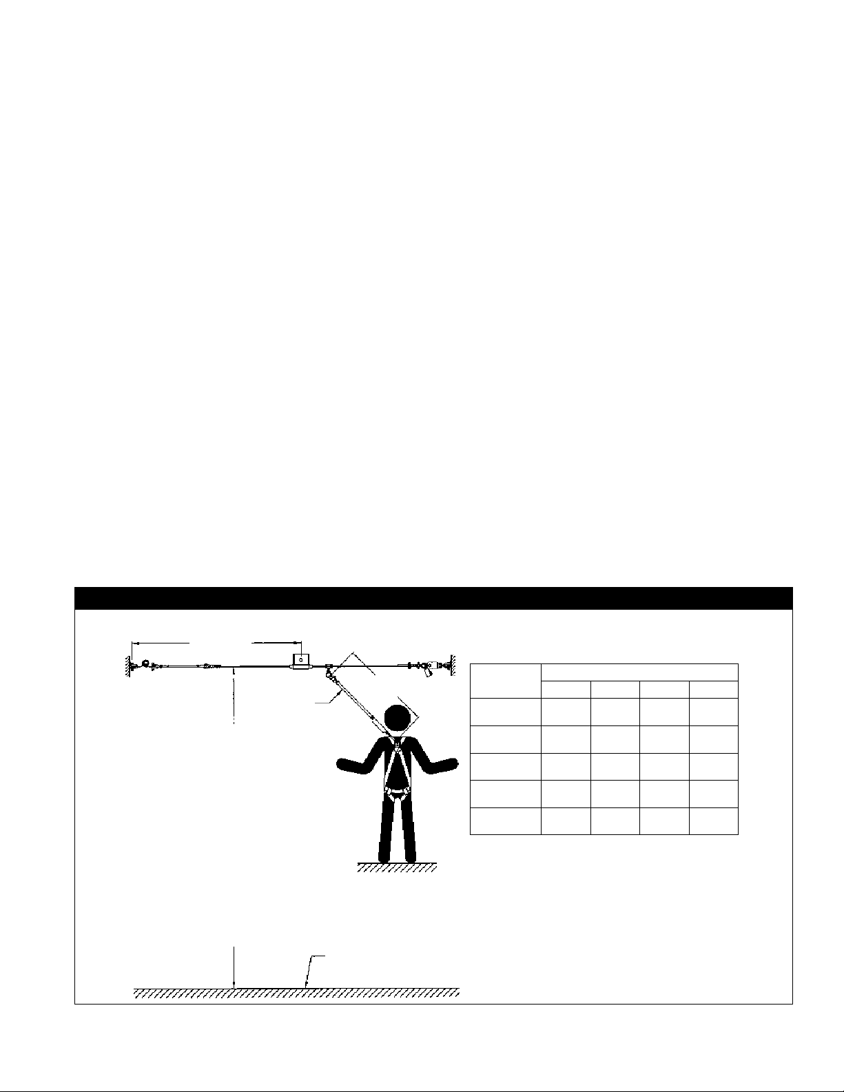
Figure 6 - Energy Absorbing Lanyard Clearance Requirements
Span Length
Energy Absorbing
Lanyard
Required Clearance from nearest lower
level or obstruction to HLL system height:
1. Find your Longest Span Length row
in the Clearance Table.
2. Find your Lanyard Length column in
the Clearance Table.
3. The required clearance is where the
Longest Span Length row intersects
the Lanyard Length column.
Example: Span is 24 ft (7 m); Lanyard
Length is 5 ft (1.5 m). Your Required
Clearance is 18 ft - 11 in (5.8 m).
Use this distance to determine if adequate
clearance exists in the event of a fall. If
clearance is inadequate, add intermediate
brackets to reduce span length, or reduce
your lanyard length and reevaluate
required clearance.
Energy Absorbing
Lanyard Length
Lower Level
or Obstruction
3M Fall Protection Energy Absorbing Lanyards
Longest Span
Lenght: ft (m)
>0 but ≤10
(>0 but ≤3)
10 - 15
(3 - 4.5)
15 - 20
(4.5 - 6)
20 - 25
(6 - 7.6)
25 - 30
(7.6 - 9)
> Greater Than
≤ Less Than or Equal To
Clearance Table
Energy Absorbing Lanyard Length: ft-in (m)
3 4 5 6
14’-11”
(4.5 m)
15’-7”
(4.7 m)
16’-2”
(4.9 m)
16’-11”
(5.2 m)
17’-6”
(5.3 m)
15’-11”
(4.9 m)
16’-7”
(5.1 m)
17’-2”
(5.2 m)
17’-11”
(5.5 m)
18’-6”
(5.6 m)
16’-11”
(5.2 m)
17’-7”
(5.4 m)
18’-2”
(5.5 m)
18’-11”
(5.8 m)
19’-6”
(5.9 m)
17’-11”
(5.5 m)
18’-7”
5.7 m)
19’-2”
(5.8 m)
19’-11”
(6.1 m)
20’-6”
(6.2 m)
5
Page 6
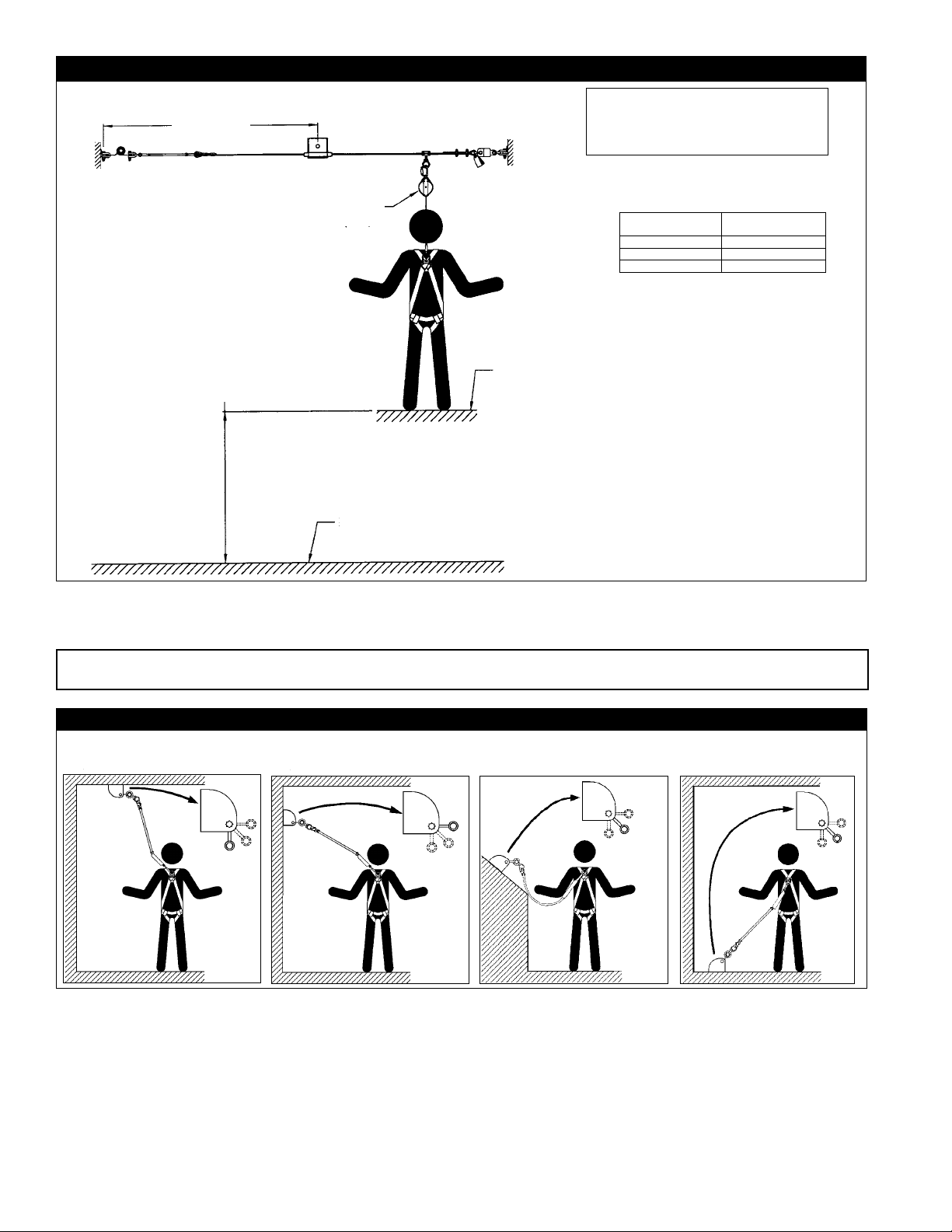
Figure 7 - Self Retracting Lifeline Clearance Requirements
Span Length
WARNING: This information only applies
when the HLL and SRL are located
overhead and above the level of the
harness attachment point, and the user is
standing.
Required Clearance from nearest
lower level or obstruction to working
level:
4. Find your longest span length
row in the clearance table.
5. Read the required clearance
distance from the distance
column to determine if adequate
clearance exists in the event
of a fall. If there is inadequate
clearance, add intermediate
brackets to reduce the span
length and reevaluate your
required clearance.
Example: Span is 16 ft (5 m), Clearance required
is 8 ft (2.5 m).
Self Retracting
Lifeline (SRL)
Lower Level or
Obstruction
Working
Level
>0 (0) but ≤10 (3) 6’-11” (2.1)
> Greater Than
≤ Less Than or Equal To
Clearance Table
3M Fall Protection Self Retracting
Longest Span
Length: ft (m)
10 (3) - 20 (6) 8’-0” (2.4)
20 (6) - 30 (90) 9’-1” (2.8)
Lifelines
Required Distance:
ft-in (m)
Step 2. Determine the correct orientation of the intermediate brackets. Depending on the positioning of
the cable, the intermediate brackets may be installed in one of three orientations. See Figure 8 for
the bracket orientations.
Note: A maximum free fall distance of 6 ft. must be maintained in all bracket positions; a system with brackets
mounted below the user should only be used for fall restraint applications.
Figure 8 - Bracket Orientations
Overhead
To the side
At an angle
Below
Step 3. To attach the cable to the rst anchor point, link one pair of shackles together, then connect
one side of the linked shackles to the anchor using the included nut and bolt. Connect the
other side of the shackles to the Zorbit that’s connected to the turnbuckle. See Figure 9. The
horizontal lifeline system may be secured directly to the anchorage if the anchorage incorporates
a connecting element that meets the requirements specied in section 2.4. The user must supply
the anchorage hardware. Tighten bolts and nuts used to connect the system to the anchorage
connectors. Slide the Sayink sleeve(s) onto the lifeline before terminating the other end of the
cable to the anchor.
6
Page 7
Step 4. If additional intermediate brackets are purchased,
slide all of the cable guides from the brackets onto
the cable before installing the cable.
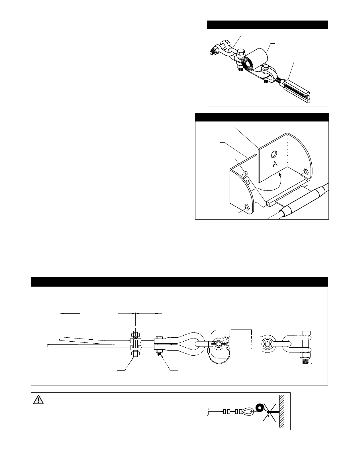
Step 5. The intermediate brackets are composed of three
parts: two side plates and a cable guide. Each of
the plates is stamped with the letter “A” or “B”.
See Figure 10. To assemble a bracket, start by
placing a cable guide into Part A at the appropriate
angle as determined in Step 2. Then slide Part
B onto the cable guide at the same angle and
nestle Part B into Part A. Place the assembled
bracket at its designated anchor point and anchor
it by placing the user supplied bolt through a at
washer and then though the mated holes in the
bracket and into the anchor point. The bolt
may be installed through the anchor and
into the bracket if preferred, but the washer
must remain inside the bracket, between the
bracket and the bolt head or nut. Torque the
anchor hardware to 55 ft./lbs (75 nM).
Figure 9 - Cable Termination
Shackles
Zorbit Shock
Absorber
Turnbuckle
Figure 10 - Bracket Assembly
Part A
Part B
Step 6. Before terminating the second end of the
horizontal lifeline, unthread the turnbuckle
on the rst end so that only four threads are
visible inside the turnbuckle body. This will
allow for maximum tensioning of the system
after anchoring the second end. Install all of
the Sayink sleeves onto the cable before
terminating the second end.
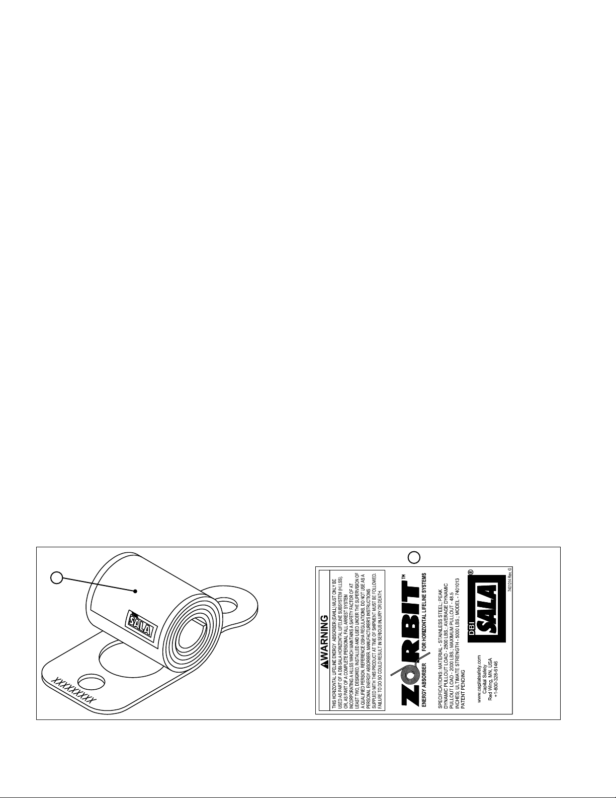
Step 7. To terminate the second end of the cable
to its anchor, attach the shackles to the
anchor and Zorbit as described in Step 3. Then attach the thimble and connecting hardware to
the Zorbit. See Figure 11. Slide the lifeline through the thimble. Remove excess slack by pulling
the wire rope through the thimble and cable clip. Maintain tension while torquing the cable clip
nut and the thimble clip nut to the values specied in Figure 11. Tension the wire rope by turning
the turnbuckle at the other end of the installation. The unrestrained turnbuckle jaw end must be
prevented from turning to prevent twisting the wire rope. The wire rope must be tensioned until
the sag on the system at mid-span, between intermediate brackets, is two inches or less, with no
weight on the wire rope.
Figure 11 - Thimble/Cable Clip End Termination
Sayine Wire Rope HLL System End Termination
8” (20 cm) Min.
2 1./2” ± 1/2”
(6.35 cm ± 1.25 cm)
Cable Guide
Cable Clip
Torque to 45 ft/lbs
Thimble/Cable Clip
Torque to 40 ft/lbs (54 Nm)
(61 Nm)
CAUTION: Do not rigidly mount Zorbit to structure or
stanchion. May cause failure due to bending. Mount so Zorbit
can pivot and move freely as shown in Figures 9 and 11.
7
Page 8

4.0 OPERATION AND USE
WARNING: Consult your doctor if there is reason to doubt your tness to absorb the impact from a fall arrest.
Age and tness can affect your ability to withstand fall arrest forces. Pregnant women and minors must not use
the Sayine Multi-span Wire Rope Horizontal Lifeline System.
4.1 BEFORE EACH USE inspect this equipment according to steps listed in section 6.4. Do not use this
equipment if inspection reveals an unsafe or defective condition. Plan your use of the fall protection
system prior to exposing workers to dangerous situations. Consider all factors affecting your safety
before using this system.
A. Read and understand all manufacturer’s instructions for each component of the personal fall arrest
system. All 3M Fall Protection harnesses and connecting subsystems are supplied with separate user
instructions. Keep all instructions for future reference.
B. Review sections 1.0 and 2.0 to ensure system limitations and other requirements have been adhered to.
Review applicable information regarding system clearance criteria, and ensure changes have not been
made to the system installation (i.e. length), or occurred at the job site, that could affect the required
fall clearance. Do not use the system if changes are required.
4.2 USE OF THE SYSTEM:
A. PERSONAL FALL ARREST SYSTEM COMPONENTS: Inspect and don the full body harness according
to manufacturer’s instructions. Attach the connecting subsystem (energy absorbing lanyard or self
retracting lifeline) to the dorsal connection on the harness. If a self retracting lifeline (SRL) is used, 3M
Fall Protection recommends using SRLs that are 20 feet (6 m) long or shorter. The weight of longer SRLs
may cause the Sayink sleeve to catch on intermediate brackets, causing the lifeline to extend which may result in an
unexpected swing fall.
WARNING: If the Sayink sleeve catches on an intermediate bracket, the SRL lifeline may extend while the
worker moves along the HLL. This will increase fall distance and create a swing fall hazard which may result in
serious injury or death.
B. CONNECTING TO THE HLL SYSTEM: Approach the work area using the appropriate access equipment.
Connect the personal fall arrest system to one of the D-rings on a Sayink sleeve on the HLL.
Connectors must meet all compatibility and strength requirements.
C. WALKING ALONG THE SYSTEM: Once attached to the Sayine System, the Sayink Sleeve will follow
the user along the lifeline and will automatically pass over each intermediate support bracket.
WARNING: Movement along the Sayine System must be done manually by the user of the system. Never
allow moving stock (such as railcars) to move the user along the Sayine System. This could cause serious
injury or death.
D. HAZARDOUS SITUATIONS: Do not take unnecessary risks, such as jumping or reaching too far from
the edge of the working surface. Do not allow the connecting subsystem to pass under arms or between
feet. To avoid inadequate fall clearance, do not climb above the HLL. To avoid swing fall hazards, do not
work too far from either side of the HLL.
E. TWO PERSONS CONNECTED TO THE HLL: When a person falls while connected to the HLL, the
system will deect. If two persons are connected to the same HLL, and one person falls, the second
person may be pulled off the working surface due to deection. The potential for the second person
falling increases as the HLL span length increases. The use of independent HLL systems for each person,
or shorter span length, is recommended to minimize the potential of the second person falling.
F. FREE FALL: The personal fall arrest system must be rigged to limit free falls to 6 ft. (1.8 m) or less
when using an energy absorbing lanyard, or such that the SRL is overhead and without slack, according
to OSHA requirements.
G. SHARP EDGES: Avoid working where the connecting subsystem or other system components will be in
contact with, or abrade against, unprotected sharp edges. If working around sharp edges is unavoidable,
provide protection by securing a heavy pad or other means over the exposed edge.
H. IN THE EVENT OF A FALL: The responsible party must have a rescue plan and the ability to implement
a rescue. Tolerable suspension time in a full body harness is limited, so a prompt rescue is critical.
8
Page 9

IMPORTANT: Use care when handling an expended Zorbit energy absorber. The tearing of the energy absorber
material produces extremely sharp edges.
I. RESCUE: With the number of potential scenarios for a worker requiring rescue, an on site rescue team
is benecial. The rescue team is given the tools, both in equipment and techniques, so it can perform a
successful rescue. Training should be provided on a periodic basis to ensure rescuers’ prociency.
4.3 SYSTEM REMOVAL: When no longer required, the HLL system should be removed from the job site. To
slacken the HLL, loosen the turnbuckle until tension is removed from the wire rope. Disconnect the HLL
system from the anchorages. Ensure there are no knots or kinks in the wire rope before storage.
5.0 TRAINING
5.1 It is the responsibility of all users of this equipment to understand these instructions, and to be trained in
the correct installation, use, and maintenance of this equipment. These individuals must be aware of the
consequences of improper installation or use of this equipment. This user manual is not a substitute for a
comprehensive training program. Training must be provided on a periodic basis to ensure prociency of the
users.
6.0 INSPECTION
6.1 BEFORE EACH INSTALLATION: Inspect the Zorbit HLL energy absorbers, kit components, and other
system components according to these or other manufacturer’s instructions. System components must be
formally inspected by a Competent1 person (other than the user). Formal inspections should concentrate
on visible signs of deterioration or damage to the system components. Items found to be defective must be
replaced. Do not use components if inspection reveals an unsafe or defective condition. Record results of
each inspection in the inspection and maintenance log in section 11.0 of this manual.
6.2 INSTALLED SYSTEMS: An inspection of the HLL system by a Competent person must be completed after
the system is installed. The system must be periodically inspected by a Competent person when left installed
for an extended period. Periodic inspections should be performed at least monthly, or more frequently when
site conditions and use warrant. Inspections of installed systems should include the inspection steps listed in
section 6.4.
6.3 Annually: A Competent Person shall inspect the entire system including the anchorage points. Inspect for
deterioration or damage. Items found to be defective must be replaced. Do not use components if inspection
reveals an unsafe or defective condition. Record the results of each inspection in the Inspection and
Maintenance Log in section 11.0 of this manual.
6.4 BEFORE SYSTEM USE:
Step 1. Inspect the turnbuckle for damage. Ensure at least four threads are visible inside the turnbuckle
body. Look for any cracks or deformities in the metal. Inspect metal components for rust or corrosion that
may affect their strength or operation.
Step 2. Inspect the wire rope for rust, corrosion, broken wires, or other obvious faults. Inspect the HLL
for proper tension. Inspect all hardware (fasteners, shackles, wire rope cable clips, etc.) securing the HLL
assembly to ensure they are present and properly installed.
Step 3. Inspect the Sayink Sleeve for excessive wear, damage, or corrosion.
Step 4. Inspect the Zorbit HLL energy absorber for extension or deformities. There should be no tearing
of the metal between holes in the Zorbit coiled section. Increase inspection frequency if the Zorbit is
exposed to prolonged vibration. Extended Zorbit HLL energy absorbers must be removed from service and
destroyed, or marked for training only. Inspect securing hardware for strength and function.
Step 5. Inspect the intermediate brackets for wear or damage. Check brackets to make certain they are
securely attached. Make certain all installed Sayink sleeves pass freely through the intermediate brackets
when moving along the system during normal use.
Step 6. Inspect system labels. The labels must be present and fully legible. See section 9.0. Replace labels
if missing or illegible.
IMPORTANT: If this equipment is subjected to the forces of a fall arrest, it must be removed from
service and destroyed, or returned to 3M Fall Protection for inspection or repair.
6.5 If inspection reveals an unsafe or defective condition, remove unit from service and destroy, or contact 3M
Fall Protection for possible repair.
1 Competent Person: One who is capable of identifying existing and predictable hazards in the surroundings or working conditions which are
unsanitary, hazardous, or dangerous to employees, and who has authorization to take prompt corrective measures to eliminate them.
9
Page 10
6.6 USER EQUIPMENT: Inspect harnesses and energy absorbing lanyards or SRL’s used with the HLL system
according to manufacturer’s instructions.
7.0 MAINTENANCE, SERVICE, STORAGE
7.1 MAINTENANCE: The Sayine components require no scheduled maintenance, other than repair or
replacement of items found defective during inspection. See section 6.0.
7.2 CLEANING: If components become heavily soiled with grease, paint, or other substances, clean with
appropriate cleaning solutions.
Remove dirt from the cable using a ber brush. Do not use a wire brush and do not apply any solvents or
lubricants without prior approval from 3M Fall Protection.
Clean all other Sayine components using a nonabrasive cloth and hot water/mild detergent mix. Dry with
a clean cloth. Do not use solvents to clean any Sayine Component. Do not use caustic chemicals that could
damage system components.
7.3 USER EQUIPMENT: Maintain, service, and store system components according to manufacturer’s
instructions for each component.
8.0 SPECIFICATIONS
8.1 MATERIALS: 8.2 ENERGY ABSORBER PERFORMANCE:
Zorbit Energy Absorber: Stainless steel Peak Dynamic Pullout Load: 2,500 lbs. (11 kN)
Wire Rope: 3/8 inch diameter, 7x19
galvanized steel
Bolts: Grade 5 or Grade 8 zinc plated steel Maximum Pullout: 48.5 inches (123 cm)
Nuts: Zinc plated steel Minimum Tensile Strength: 5,000 lbs. (22 kN)
Intermediate Brackets: 11 ga. hot rolled
steel, zinc plated
Sayink Sleeve Assembly: alloy steel
Shackles: Galvanized steel, 5,000 lbs.
(22 kN) minimum tensile strength
Thimbles: Galvanized steel
Turnbuckle: Galvanized steel, 5,000 lbs.
(22 kN)minimum tensile strength
Cable Clips: Galvanized steel
Average Dynamic Pullout Load: 2,000 lbs. (9 kN)
Patents Pending
9.0 LABELING
9.1 The following labels must be present and fully legible:
A
10
A
Page 11

A
E
B
D
F
C
B C
D D
A
WARNING
E E
F
F
11
Page 12

Page 13

Page 14

INSPECTION AND MAINTENANCE LOG
SERIAL NUMBER:
MODEL NUMBER:
DATE PURCHASED: DATE OF FIRST USE:
INSPECTION DATE INSPECTION ITEMS
NOTED
Approved By:
Approved By:
Approved By:
Approved By:
Approved By:
Approved By:
Approved By:
Approved By:
CORRECTIVE ACTION MAINTENANCE
PERFORMED
Approved By:
Approved By:
Approved By:
Approved By:
Approved By:
Approved By:
Approved By:
Approved By:
Approved By:
Approved By:
Approved By:
Page 15

7603000
7603020
7603040
7603060
This instruction applies to the following product models:
7603070
7603071
7603072
7603073
Additional Model Numbers may appear on the next printing of this instruction.
7603074
7603075
7603076
7603079
7603080
7603100
7603120
7603140
7603160
7603180
7603200
7603220
7603240
7603260
7603299
7608001
Page 16

ISO
USA
3833 SALA Way
Red Wing, MN 55066-5005
Toll Free: 800.328.6146
Phone: 651.388.8282
Fax: 651.388.5065
3Mfallprotection@mmm.com
Brazil
Rua Anne Frank, 2621
Boqueirão Curitiba PR
81650-020
Brazil
Phone: 0800-942-2300
falecoma3m@mmm.com
Mexico
Calle Norte 35, 895-E
Col. Industrial Vallejo
C.P. 02300 Azcapotzalco
Mexico D.F.
Phone: (55) 57194820
3msaludocupacional@mmm.com
Colombia
Compañía Latinoamericana de Seguridad S.A.S.
Carrera 106 #15-25 Interior 105 Manzana 15
Zona Franca - Bogotá, Colombia
Phone: 57 1 6014777
fallprotection-co@mmm.com
U.S. PRODUCT WARRANTY, LIMITED REMEDY
AND LIMITATION OF LIABILITY
WARRANTY: THE FOLLOWING IS MADE IN LIEU OF ALL WARRANTIES OR CONDITIONS, EXPRESS
OR IMPLIED, INCLUDING THE IMPLIED WARRANTIES OR CONDITIONS OF MERCHANTABILITY OR
FITNESS FOR A PARTICULAR PURPOSE.
Unless otherwise provided by applicable law, 3M fall protection products are warranted against factory
defects in workmanship and materials for a period of one year from the date of installation or fi rst use
by the original owner.
LIMITED REMEDY: Upon written notice to 3M, 3M will repair or replace any product determined by
3M to have a factory defect in workmanship or materials. 3M reserves the right to require product be
returned to its facility for evaluation of warranty claims. This warranty does not cover product damage
due to wear, abuse, misuse, damage in transit, failure to maintain the product or other damage beyond
3M’s control. 3M will be the sole judge of product condition and warranty options.
This warranty applies only to the original purchaser and is the only warranty applicable to 3M’s fall
protection products. Please contact 3M’s customer service department at 800-328-6146 or via email at
3MFallProtection@mmm.com for assistance.
LIMITATION OF LIABILITY: TO THE EXTENT PERMITTED BY APPLICABLE LAW, 3M IS NOT
LIABLE FOR ANY INDIRECT, INCIDENTAL, SPECIAL OR CONSEQUENTIAL DAMAGES INCLUDING,
BUT NOT LIMITED TO LOSS OF PROFITS, IN ANY WAY RELATED TO THE PRODUCTS REGARDLESS
OF THE LEGAL THEORY ASSERTED.
Canada
260 Export Boulevard
Mississauga, ON L5S 1Y9
Phone: 905.795.9333
Toll-Free: 800.387.7484
Fax: 888.387.7484
3Mfallprotection-ca@mmm.com
EME A (Europe, Middle East, Africa)
EMEA Headquarters:
5a Merse Road
North Moons Moat
Redditch, Worcestershire
B98 9HL UK
Phone: + 44 (0)1527 548 000
Fax: + 44 (0)1527 591 000
informationfallprotection@mmm.com
France:
Le Broc Center
Z.I. 1re Avenue - BP15
06511 Carros Le Broc Cedex
France
Phone: + 33 04 97 10 00 10
Fax: + 33 04 93 08 79 70
informationfallprotection@mmm.com
Australia & New Zealand
95 Derby Street
Silverwater
Sydney NSW 2128
Australia
Phone: +(61) 2 8753 7600
Toll-Free : 1800 245 002 (AUS)
Toll-Free : 0800 212 505 (NZ)
Fax: +(61) 2 8753 7603
anzfallprotectionsales@mmm.com
3M.com/FallProtection
Asia
Singapore:
1 Yishun Avenue 7
Singapore 768923
Phone: +65-6450 8888
Fax: +65-6552 2113
TotalFallProtection@mmm.com
Shanghai:
19/F, L’Avenue, No.99 Xian Xia Rd
Shanghai 200051, P R China
Phone: +86 21 62539050
Fax: +86 21 62539060
3MFallProtecton-CN@mmm.com
Korea:
3M Koread Ltd
20F, 82, Uisadang-daero,
Yeongdeungpo-gu, Seoul
Phone: +82-80-033-4114
Fax: +82-2-3771-4271
TotalFallProtection@mmm.com
Japan:
3M Japan Ltd
6-7-29, Kitashinagawa, Shinagawa-ku, Tokyo
Phone: +81-570-011-321
Fax: +81-3-6409-5818
psd.jp@mmm.com
9001
Page 17

psd.jp@mmm.com
Fax: +81-3-6409-5818
Phone: +81-570-011-321
6-7-29, Kitashinagawa, Shinagawa-ku, Tokyo
3M Japan Ltd
Japan:
TotalFallProtection@mmm.com
Fax: +82-2-3771-4271
Phone: +82-80-033-4114
Yeongdeungpo-gu, Seoul
20F, 82, Uisadang-daero,
3M Koread Ltd
Korea:
3MFallProtecton-CN@mmm.com
Fax: +86 21 62539060
Phone: +86 21 62539050
Shanghai 200051, P R China
19/F, L’Avenue, No.99 Xian Xia Rd
Shanghai:
TotalFallProtection@mmm.com
Fax: +65-6552 2113
Phone: +65-6450 8888
Singapore 768923
1 Yishun Avenue 7
Singapore:
Asia
9001
ISO
3M.com/FallProtection
anzfallprotectionsales@mmm.com
Fax: +(61) 2 8753 7603
Toll-Free : 0800 212 505 (NZ)
Toll-Free : 1800 245 002 (AUS)
Phone: +(61) 2 8753 7600
Australia
Sydney NSW 2128
Silverwater
95 Derby Street
Australia & New Zealand
informationfallprotection@mmm.com
Fax: + 33 04 93 08 79 70
Phone: + 33 04 97 10 00 10
France
06511 Carros Le Broc Cedex
Z.I. 1re Avenue - BP15
Le Broc Center
France:
informationfallprotection@mmm.com
Fax: + 44 (0)1527 591 000
Phone: + 44 (0)1527 548 000
B98 9HL UK
Redditch, Worcestershire
North Moons Moat
5a Merse Road
EMEA Headquarters:
EMEA (Europe, Middle East, Africa)
3Mfallprotection-ca@mmm.com
Fax: 888.387.7484
Toll-Free: 800.387.7484
Phone: 905.795.9333
Mississauga, ON L5S 1Y9
260 Export Boulevard
Canada
fallprotection-co@mmm.com
Phone: 57 1 6014777
Zona Franca - Bogotá, Colombia
Carrera 106 #15-25 Interior 105 Manzana 15
Compañía Latinoamericana de Seguridad S.A.S.
Colombia
3msaludocupacional@mmm.com
Phone: (55) 57194820
Mexico D.F.
C.P. 02300 Azcapotzalco
Col. Industrial Vallejo
Calle Norte 35, 895-E
Mexico
falecoma3m@mmm.com
Phone: 0800-942-2300
Brazil
81650-020
Boqueirão Curitiba PR
Rua Anne Frank, 2621
Brazil
3Mfallprotection@mmm.com
Fax: 651.388.5065
Phone: 651.388.8282
Toll Free: 800.328.6146
Red Wing, MN 55066-5005
3833 SALA Way
USA
QUE SOIT LA THÉORIE LÉGALE INVOQUÉE.
INCLUANT , SANS S’Y LIMITER, LA PERTE DE PROFIT, LIÉS DE QUELQUE MANIÈRE AUX PRODUITS, QUELLE
TENU POUR RESPONSABLE DE TOUT DOMMAGE INDIRECT, ACCESSOIRE, SPÉCIFIQUE OU CONSÉCUTIF
LIMITATION DE RESPONSABILITÉ : DANS LES LIMITES PRÉVUES PAR LES LOIS LOCALES, 3M NE SERA
obtenir de l’aide.
protection antichute de 3M. Veuillez communiquer avec le service à la clientèle de 3M de votre région pour
Cette garantie s’applique uniquement à l’acheteur initial et est la seule garantie applicable aux produits de
de 3M. 3M jugera seul de l’état du produit et des options de garantie.
subis pendant l’expédition, le manque d’entretien du produit ou d’autres dommages en dehors du contrôle
pas les dommages au produit résultant de l’usure, d’un abus ou d’une mauvaise utilisation, les dommages
retour du produit dans ses installations afi n d’évaluer la réclamation de garantie. Cette garantie ne couvre
défaut de fabrication en usine ou de matériaux, tel que déterminé par 3M. 3M se réserve le droit d’exiger le
RECOURS LIMITÉ : Moyennant un avis écrit à 3M, 3M réparera ou remplacera tout produit présentant un
de la première utilisation par le propriétaire initial.
de fabrication en usine et de matériaux pour une période d’un (1) an à compter de la date d’installation ou
Sauf disposition contraire de la loi, les produits de protection antichute 3M sont garantis contre tout défaut
MARCHANDE ET À L’ADAPTATION À UN USAGE PARTICULIER.
IMPLICITES, Y COMPRIS LES GARANTIES OU LES CONDITIONS IMPLICITES RELATIVES À LA QUALITÉ
ET LIMITATION DE RESPONSABILITÉ
GARANTIE INTERNATIONALE DU PRODUIT, RECOURS LIMITÉ
GARANTIE : CE QUI SUIT REMPLACE TOUTES LES GARANTIES OU CONDITIONS, EXPRESSES OU
LEGAL THEORY ASSERTED.
LIMITED TO LOSS OF PROFITS, IN ANY WAY RELATED TO THE PRODUCTS REGARDLESS OF THE
FOR ANY INDIRECT, INCIDENTAL, SPECIAL OR CONSEQUENTIAL DAMAGES INCLUDING, BUT NOT
LIMITATION OF LIABILITY: TO THE EXTENT PERMITTED BY LOCAL LAWS, 3M IS NOT LIABLE
protection products. Please contact 3M’s customer service department in your region for assistance.
This warranty applies only to the original purchaser and is the only warranty applicable to 3M’s fall
3M’s control. 3M will be the sole judge of product condition and warranty options.
due to wear, abuse, misuse, damage in transit, failure to maintain the product or other damage beyond
returned to its facility for evaluation of warranty claims. This warranty does not cover product damage
3M to have a factory defect in workmanship or materials. 3M reserves the right to require product be
LIMITED REMEDY: Upon written notice to 3M, 3M will repair or replace any product determined by
by the original owner.
defects in workmanship and materials for a period of one year from the date of installation or fi rst use
Unless otherwise provided by local laws, 3M fall protection products are warranted against factory
FITNESS FOR A PARTICULAR PURPOSE.
OR IMPLIED, INCLUDING THE IMPLIED WARRANTIES OR CONDITIONS OF MERCHANTABILITY OR
AND LIMITATION OF LIABILITY
GLOBAL PRODUCT WARRANTY, LIMITED REMEDY
WARRANTY: THE FOLLOWING IS MADE IN LIEU OF ALL WARRANTIES OR CONDITIONS, EXPRESS
Page 18

De nouveaux numéros de modèles peuvent apparaître lors de la prochaine impression de ces instructions.
7608001
7603299
7603260
7603240
7603220
7603200
7603180
7603160
7603140
7603120
7603100
7603080
7603079
7603076
7603075
7603074
7603073
7603072
7603071
7603070
Ces directives se rapportent aux modèles des produits suivants :
7603060
7603040
7603020
7603000
Page 19

Approuvé par :
Approuvé par :
Approuvé par :
Approuvé par :
Approuvé par :
Approuvé par :
Approuvé par :
Approuvé par :
Approuvé par :
Approuvé par :
EFFECTUÉ
ENTRETIEN
CORRECTIVES
MESURES
D’INSPECTION NOTÉS
ÉLÉMENTS
Approuvé par :
Approuvé par :
Approuvé par :
Approuvé par :
Approuvé par :
Approuvé par :
Approuvé par :
Approuvé par :
DATE D’INSPECTION
DATE D’ACHAT : DATE DE PREMIÈRE UTILISATION :
NUMÉRO DE MODÈLE
NUMÉRO DE SÉRIE :
JOURNAL D’INSPECTION ET D’ENTRETIEN
Page 20

Page 21

Page 22

11
WARNING
F
F
E E
D D
B C
C
F
D
B
E
A
A
Page 23

10
A
A
9.1 Les étiquettes suivantes doivent être présentes et entièrement lisibles :
9.0 ÉTIQUETAGE
Serre-câbles : acier galvanisé
traction minimale de 5 000 lb (22 kN).
Tendeur : acier galvanisé, résistance à la
Cosses : Acier galvanisé
à la traction minimale 5 000 lb (22 kN).
Maillons d’attache : acier galvanisé, résistance
Ensemble manchon Sayfl ink : alliage d'acier
chaud, plaqué au zinc 11 ga.
Brevets en instance
2 000 lb (9 kN)
Charge de résistance dynamique moyenne :
2 500 lb (11 kN)
D’ÉNERGIE :
Supports intermédiaires : acier laminé à
Écrous : acier zingué Résistance à la traction minimale : 5 000 lb (22 kN)
Boulons : acier zingué de classe 5 ou 8 Résistance maximale : 48,5 po (116 cm)
(0,95 cm), acier galvanisé 7 x 19
Câble métallique : diamètre de 3/8 po
Absorbeur d’énergie Zorbit : acier inoxydable Charge de résistance dynamique maximale :
8.1 MATÉRIAUX : 8.2 PERFORMANCES DE L’ABSORBEUR
8.0 SPÉCIFICATIONS
directives du fabricant.
7.3 ÉQUIPEMENT DE L’UTILISATEUR : nettoyez, réparez et entreposez les composants du système selon les
Sayfl ine. N’utilisez pas de produits chimiques caustiques pouvant endommager les composants du système.
détergent doux. Séchez avec un chiffon propre. N'utilisez pas de solvants pour nettoyer les composants
Nettoyez tous les autres composants Sayfl ine à l'aide d'un chiffon doux et un mélange d'eau chaude et de
A
aucun solvant ou lubrifi ant sans approbation antérieure de DBI/SALA.
Enlevez les saletés sur le câble avec une brosse de fi bres. N'utilisez pas de brosse métallique et n'appliquez
nettoyés avec les produits de nettoyage appropriés.
7.2 NETTOYAGE : les composants souillés de graisse, de peinture ou de toute autre substance doivent être
le remplacement des éléments jugés défectueux lors d'une inspection. Voir Section 6.0.
7.1 ENTRETIEN: les composants Sayfl ine ne nécessitent aucun entretien périodique autre que la réparation ou
7.0 ENTRETIEN, RÉPARATION ET ENTREPOSAGE
de vie auto-rétractable utilisés avec le système de ligne de vie horizontale selon les instructions du fabricant.
6.6 ÉQUIPEMENT DE L’UTILISATEUR : inspectez les harnais et les longes absorbeuses d'énergie ou la ligne
l’équipement du service et détruisez-le, ou communiquez avec DBI/SALA pour une éventuelle réparation.
6.5 Si l’inspection révèle l’existence d’un défaut ou d’une condition non sécuritaire, retirez immédiatement
immédiatement du service et détruit, ou retourné à DBI/SALA pour inspection ou réparation.
IMPORTANT : si l’équipement a été soumis à des forces résultant d’un arrêt de chute, il doit être retiré
Page 24

9
insalubres, peligrosas o peligrosas para los empleados, y que tiene autorización para tomar medidas correctivas inmediatas para eliminarlos.
1- Persona competente: alguien que es capaz de identifi car peligros existentes y predecibles en el entorno o condiciones de trabajo que son
Voir Section 9.0. Remplacez les étiquettes illisibles ou manquantes.
Étape 6. Vérifi ez les étiquettes du système. Les étiquettes doivent être présentes et entièrement lisibles.
normale.
encombre dans les supports intermédiaires lors de déplacements le long du système pendant une utilisation
vous qu'ils sont solidement attachés. Assurez-vous que tous les manchons Sayfl ink installés passent sans
Étape 5. Vérifi ez si les supports intermédiaires sont usés ou endommagés. Vérifi ez les supports et assurez-
Vérifi ez la résistance et le bon fonctionnement du matériel de fi xation.
étirés, ou marquez-les pour qu’ils soient utilisés uniquement dans le cadre d’un programme de formation.
une vibration prolongée. Retirez et détruisez les absorbeurs d’énergie pour lignes de vie horizontales Zorbit
extensible du système Zorbit. Augmentez la fréquence des inspections si le système Zorbit est exposé à
extension ou déformation. Le système ne doit présenter aucun bris de métal entre les trous de la section
Étape 4. Vérifi ez si l’absorbeur d’énergie pour ligne de vie horizontale Zorbit ne présente aucune
Étape 3. Vérifi ez si le manchon Sayfl ink n'est pas excessivement usé, endommagé ou corrodé.
vie horizontale pour s’assurer qu’il ne manque aucun accessoire et qu’ils sont bien installés.
fi xation, maillons d’attache, serre-câbles pour câbles métalliques, etc.) en fi xant l’ensemble de la ligne de
nu. Vérifi ez si la ligne de vie horizontale a une tension appropriée. Vérifi ez tout le matériel (dispositifs de
Étape 2. Vérifi ez si le câble métallique est rouillé, corrodé, brisé ou tout autrement défectueux à l’œil
rouillés ou corrodés car cela pourrait nuire à leur solidité ou à leur fonctionnement.
du tendeur. Identifi ez toute fi ssure ou déformation du métal. Vérifi ez si les composants métalliques sont
Étape 1. Vérifi ez si le tendeur est endommagé. Assurez-vous que quatre fi ls sont visibles dans le corps
6.4 AVANT L’UTILISATION DU SYSTÈME :
section 11.0 de ce manuel.
équipement. Consignez les résultats de chaque inspection dans le journal d’inspection et d’entretien de la
doivent être remplacés. Si une inspection révèle un état non sécuritaire ou douteux, n’utilisez pas cet
d’ancrage. Inspectez en vue de déceler toute détérioration ou tout dommage. Les éléments défectueux
6.3 Une fois par an : une personne qualifi ée doit inspecter l’ensemble du système, y compris les points
section 6.4.
site les justifi ent. Les inspections des systèmes installés doivent comprendre les étapes d’inspection de la
devraient être faites au moins chaque mois ou plus fréquemment lorsque les conditions et l'utilisation du
personne competente lorsqu’on le laisse installé pour une période prolongée. Des inspections périodiques
personne competente après l’installation du système. Le système doit être inspecté périodiquement par une
6.2 SYSTÈMES INSTALLÉS : une inspection du système de ligne de vie horizontale doit être menée par une
d’entretien de ce manuel.
Enregistrez les résultats de toutes les inspections formelles dans la section 11.0 du journal d’inspection et
être remplacés. Si une inspection révèle un état non sécuritaire ou douteux, n’utilisez pas cet équipement.
visibles de détérioration ou de dommages aux éléments du système. Les éléments défectueux doivent
(autre que l’utilisateur). Les inspections formelles doivent être centrées sur les signes
1
personne competente
aux autres instructions du fabricant. Les éléments du système doivent être formellement inspectés par une
les composants de la trousse et les autres composants du système, conformément à ces instructions et
6.1 AVANT CHAQUE INSTALLATION : inspectez les absorbeurs d’énergie pour ligne de vie horizontale Zorbit,
6.0 INSPECTION
réguliers afi n de garantir la compétence des utilisateurs.
ne peut se substituer à un programme de formation complet. Cette formation doit être menée à intervalles
été sensibilisés sur les conséquences d'une mauvaise installation de cet équipement. Ce guide d'utilisation
formation pour installer, utiliser et entretenir correctement cet équipement. Les utilisateurs doivent avoir
5.1 Tous les utilisateurs de cet équipement sont tenus de comprendre les instructions et de suivre une
5.0 FORMATION
Assurez-vous qu’il n’y a pas de nœuds ou de plis dans le câble métallique avant de l’entreposer.
ait plus de tension dans le câble métallique. Décrochez le système de ligne de vie horizontale des ancrages.
lorsqu’il n’est plus utile. Pour relâcher la ligne de vie horizontale, desserrez le tendeur jusqu’à ce qu’il n’y
4.3 DÉSASSEMBLAGE DU SYSTÈME : le système de ligne de vie horizontale doit être retiré du chantier
périodique afi n d'assurer l'effi cacité des sauveteurs.
équipement qu’en techniques, pour réussir le sauvetage. La formation devrait être fournie sur une base
utile d’avoir une équipe de sauvetage sur place. L’équipe de sauvetage doit avoir les outils, autant en
I. SAUVETAGE : avec le nombre de scénarios possibles lors du sauvetage d’un ouvrier, il peut être
absorbeur d’énergie peut former des rebords extrêmement tranchants.
IMPORTANT : manipulez toujours avec précaution un absorbeur d’énergie Zorbit tendu. Le bris de matériel d’un
Page 25

8
limité, le sauvetage doit se faire au plus vite.
mettre en œuvre. Comme le temps de suspension acceptable dans le harnais de sécurité complet est
H. EN CAS DE CHUTE : la personne responsable doit avoir un plan de sauvetage et la capacité de le
épais ou d'autres moyens placés sur l'arête tranchante exposée.
devez utiliser cet équipement près d'arêtes tranchantes, prévoyez une protection comme un coussin
du système seront en contact avec ou s’useront contre des rebords tranchants non protégés. Si vous
G. ARÊTES TRANCHANTES : évitez de travailler où le sous-système de connexion ou d’autres composants
auto-rétractable soit au-dessus de la tête sans relâchement, conformément aux exigences de l’OSHA.
chutes libres lorsque vous utilisez une longe absorbeuse d'énergie, ou de telle sorte que la ligne de vie
F. CHUTE LIBRE : le dispositif antichute personnel doit être fi xé à 6 pi (1,8 m) ou moins afi n de limiter les
minimiser le risque de chute de la deuxième personne.
indépendants pour chaque personne, ou une longueur de portée plus courte est recommandée afi n de
avec la portée de la ligne de vie horizontale. L’utilisation de systèmes de ligne de vie horizontale
de la surface de travail à cause de la fl exion Le risque de chute pour la deuxième personne augmente
la même ligne de vie horizontale et qu’une personne tombe, la deuxième personne peut être tirée hors
qu’elle est fi xée à la ligne de vie horizontale, cela fait fl échir le système. Si deux personnes sont fi xées à
E. DEUX PERSONNES FIXÉES À LA LIGNE DE VIE HORIZONTALE : lorsqu’une personne tombe alors
chaque côté de la ligne de vie horizontale.
de vie horizontale. Pour éviter tout risque de chute avec effet pendulaire, ne travaillez pas trop loin de
ou entre les pieds. Afi n d’éviter une distance d'arrêt inadéquate, ne grimpez pas au-dessus de la ligne
du bord de la surface de travail. Ne laissez pas le sous-système de connexion vous passer sous les bras
D. SITUATIONS DANGEREUSES : ne prenez pas de risques inutiles, tels que sauter ou s’étirer trop loin
l'utilisateur le long du système Sayfl ine. Cela pourrait entraîner des blessures graves ou la mort.
l'utilisateur du système. Ne laissez pas des wagons en déplacement (tels que des wagonnets) déplacer
AVERTISSEMENT : les déplacements le long du système Sayfl ine doivent être effectués manuellement par
l'utilisateur le long de la ligne de vie et passera automatiquement au-dessus de chaque support intermédiaire.
C. DÉPLACEMENT AVEC LE SYSTÈME : une fois attaché au système Sayfl ine, le manchon Sayfl ine suivra
répondre à toutes les exigences de compatibilité et de résistance.
D d'accrochage sur le manchon Sayfl ink sur la ligne de vie horizontale. Les connecteurs doivent
utilisant l’équipement approprié pour y accéder. Attachez le dispositif antichute personnel à un
B. CONNEXION À LA LIGNE DE VIE HORIZONTALE : rendez-vous à l’emplacement de travail en
danger de chute avec effet pendulaire pouvant entraîner des blessures graves ou la mort.
que l'ouvrier se déplace le long de la ligne de vie horizontale. Cela augmentera la distance de chute et créera un
AVERTISSEMENT : si le manchon Sayfl ink se coince sur un support intermédiaire, la SRL peut s'étendre pendant
une extension de la ligne de vie, et pouvant entraîner un effet pendulaire inopiné.
Le manchon Sayfl ink peut se coincer sur les supports intermédiaires avec des SRL plus longues et plus lourdes, créant
rétractable (SRL) est utilisée, DBI/SALA recommande l'utilisation d'une SRL de 20 pi (6 m) ou plus courte.
d'énergie ou ligne de vie auto-rétractable) à la connexion dorsale du harnais. Si une ligne de vie autosécurité complet selon les instructions du fabricant. Fixez le sous-système de connexion (longe absorbeuse
A. COMPOSANTS DU DISPOSITIF ANTICHUTE PERSONNEL : veuillez inspecter et revêtir le harnais de
4.2 UTILISATION DU SYSTÈME :
distance d'arrêt nécessaire. N’utilisez pas le système si des changements sont nécessaires.
système (c.-à-d. la longueur) ou autre changement sur le chantier de travail, qui pourrait affecter
dégagement du système, et assurez-vous qu’aucun changement n’a été apporté à l’installation du
prérequis ont été respectés. Révisez les renseignements applicables au sujet des critères de
B. Révisez les sections 1.0 et 2.0 afi n de vous assurer que toutes les limitations du système et autres
utilisation ultérieure.
accompagnés de leurs propres instructions d’utilisation. Veuillez conserver ces instructions pour une
du dispositif antichute. Tous les harnais de DBI/SALA ainsi que leurs sous-systèmes de connexion sont
A. Prenez connaissance de toutes les instructions émises par le fabricant au sujet de chaque composant
tous les facteurs pouvant affecter la sécurité avant l’utilisation de ce système.
un dispositif antichute avant d’exposer vos ouvriers à des conditions de travail dangereuses. Tenez compte de
Si une inspection révèle un état non sécuritaire ou douteux, n’utilisez pas cet équipement. Prévoyez d’utiliser
4.1 AVANT CHAQUE UTILISATION, veuillez inspecter cet équipement selon les étapes qui fi gurent à la section 6.4.
métallique à longueur réglable Sayfl ine.
forces d'arrêt de chute. Les femmes enceintes et les mineurs ne doivent pas utiliser la ligne de vie horizontale
choc d’arrêt de chute. L’âge et le niveau de forme physique peuvent affecter votre capacité à endurer les
AVERTISSEMENT : consultez votre médecin en cas de doute quant à votre capacité physique à amortir le
4.0 FONCTIONNEMENT ET UTILISATION
Page 26

7
Couple de 40 lb-pi (54 Nm)
Cosse/Serre-câble
Figures 9 et 11.
et se déplacer librement, comme il est indiqué à dans les
Fixez le système Zorbit de telle sorte que celui-ci puisse pivoter
pourrait entraîner une défaillance en raison d’une courbure.
manière rigide à la structure ou à un poteau métallique. Cela
MISE EN GARDE : ne fi xez pas le système Zorbit de
(61 Nm)
Couple de 45 lb-pi
Serre-câble
Tendeur
Zorbit
Absorbeur de choc
Maillons d’attache
(6,35 cm ± 1,25 cm)
2 1./2 po ± 1/2 po
Guide-câble
Pièce B
Pièce A
Figure 10 - Ensemble support
Figure 9 - Raccord de câble
8 po (20 cm) min.
Raccord de l'extrémité de la ligne de vie horizontale métallique Sayfl ine
Figure 11 - Raccord de l'extrémité à la cosse/au serre-câble
supports intermédiaires, soit à 2 pouces (5 cm) ou moins, sans poids exercé sur le câble.
Le câble métallique doit être tendu jusqu'à ce que la fl èche sur le système à mi-portée, entre les
Empêchez la mâchoire non attachée du tendeur de tourner afi n d'éviter de tordre le câble métallique.
la Figure 11. Serrez le câble métallique en tournant le tendeur à l'autre extrémité de l'installation.
la tension en serrant l'écrou du serre-câble et l'écrou de la cosse au couple de valeurs précisées dans
Éliminez le jeu excédentaire en tirant le câble métallique à travers la cosse et le serre-câble. Maintenez
le matériel de connexion au Zorbit. Voir Figure 11. Faites glisser la ligne de vie à travers la cosse.
dans l'Étape 3. Ensuite, attachez la cosse et
d'attache sur l'ancrage et le Zorbit tel que décrit
câble à son ancrage, attachez les maillons
Étape 7. Pour raccorder la deuxième extrémité du
deuxième extrémité.
Sayfl ink sur le câble avant de raccorder la
extrémité. Installez tous les manchons
du système après avoir ancré la deuxième
tendeur. Cela permettra une tension maximale
4 fi ls soient visible à l'intérieur du corps du
tendeur à l'autre extrémité afi n que seulement
de la ligne de vie horizontale, desserrez le
Étape 6. Avant de raccorder la deuxième extrémité
d'ancrage au couple de 55 pi/lb (75 nM).
tête de boulon ou d'écrou. Serrez le matériel
à l'intérieur du support, entre celui-ci et la
vous le préférez, mais la rondelle doit rester
à travers l'ancrage et dans le support si
point d'ancrage. Le boulon peut être installé
trous superposés dans le support et dans le
à travers la rondelle plate et ensuite à travers les
ancrez-le en plaçant le boulon d'utilisateur fourni
assemblé sur son point d'ancrage désigné et
la pièce B dans la pièce A. Placez le support ainsi
le guide-câble selon le même angle et emboîtez
dans l'Étape 2. Ensuite, faites glisser la pièce B sur
sur la pièce A selon un angle approprié déterminé
support, commencez par placer un guide-câble
« A » ou « B ». Voir Figure 10. Pour assembler un
Chacune des plaques est estampillée de la lettre
parties : deux plaques latérales et un guide-câble.
Étape 5. Les supports intermédiaires sont composés de trois
supports sur le câble avant d'installer celui-ci.
été achetés, faites glisser tous les guide-câbles des
Étape 4. Si des supports intermédiaires supplémentaires ont
Page 27

6
ligne de vie avant de raccorder l'autre extrémité du câble à l'ancrage.
connecter le système aux connecteurs d'ancrage. Faites glisser le(s) manchon(s) Sayfl ink sur la
2.4. L'utilisateur doit fournir le matériel d'ancrage. Serrez les boulons et les écrous utilisés pour
si celui-ci comprend un élément de fi xation qui répond aux exigences spécifi ées dans la section
Figure 9. La ligne de vie horizontale peut être directement rattachée en toute sécurité à l'ancrage
boulon fournis. Connectez l'autre côté des maillons d'attache au Zorbit connecté au tendeur. Voir
entre eux, puis, connectez un côté des maillons connectés à l'ancrage à l'aide de l'écrou et du
Étape 3. Pour attacher un câble au premier point d'ancrage, connectez une paire de maillons d'attache
En dessous
6 pi-11 po (2,1)
pi-po (m)
Distance requise :
SALA
≤ Moins que ou égal à
> Plus que
20 (6) - 30 (90) 9 pi-1 po (2,8)
10 (3) - 20 (6) 8 pi-0 po (2,4)
(3)
>0 (0) mais ≤10
pi (m)
Plus longue portée :
dégagement
Lignes de vie auto-rétractables DBI-
Tableau des hauteurs de
À un angle
Travail
Niveau de
Sur le côté
Figure 8 - Sens des supports
des supports.
supports intermédiaires peuvent être installés dans un des trois sens. Voir Figure 8 pour les sens
ou obstacle
Niveau inférieur
(SRL)
rétractable
vie autoLigne de
Au-dessus
des applications de dispositif de sécurité antichute.
positions du support ; un système avec supports montés en dessous de l'utilisateur ne doit être utilisé que dans
Remarque : Une distance maximale de chute libre de 6 pi (1,80 m) doit être maintenue dans toutes les
Étape 2. Déterminez le bon sens des supports intermédiaires. En fonction du positionnement du câble, les
de dégagement requise est 8 pi (2,5 m).
Exemple : la portée est de 16 pi (5 m), la hauteur
hauteur de dégagement requise.
longueur de la portée et réévaluez votre
supports intermédiaires pour réduire la
dégagement est inadéquate, ajoutez des
en cas de chute. Si la hauteur de
une hauteur de dégagement adéquate
hauteurs afi n de déterminer s’il existe
requises présentées dans la colonne des
5. Consultez les hauteurs de dégagement
des hauteurs de dégagement.
système dans les rangées du Tableau
4. Trouvez la plus longue portée de votre
jusqu'au niveau de travail :
niveau inférieur ou de l'obstacle le plus près
Hauteur de dégagement requise à partir du
du harnais, et que l’utilisateur est debout.
situées au-dessus du niveau du point de fi xation
horizontale et la ligne de vie auto-rétractable sont
s’appliquent seulement lorsque la ligne de vie
AVERTISSEMENT : ces renseignements
Longueur de la portée
Figure 7 - Exigences en matière de dégagement de la ligne de vie auto-rétractable
Page 28

(6,2 m)
20 pi-6 po
(6,1 m)
11 po
19 pi-
(5,8 m)
19 pi-2 po
(5,7 m)
18 pi-7 po
(5,5 m)
11 po
17 pi-
(5,9 m)
19 pi-6 po
(5,8 m)
11 po
18 pi-
(5,5 m)
18 pi-2 po
(5,4 m)
17 pi-7 po
(5,2 m)
11 po
16 pi-
(5,6 m)
18 pi-6 po
(5,5 m)
11 po
17 pi-
(5,2 m)
17 pi-2 po
(5,1 m)
16 pi-7 po
(4,9 m)
11 po
15 pi-
5
≤ Moins que ou égal à
> Plus que
(5,3 m)
17 pi-6 po
(5,2 m)
11 po
16 pi-
(4,9 m)
16 pi-2 po
(4,7 m)
15 pi-7 po
(4,5 m)
11 po
14 pi-
3456
pi-po (m)
Longueur de la longe absorbeuse d'énergie :
(7,6 - 9)
25 - 30
(6 - 7,6)
20 - 25
(4,5 - 6)
15 - 20
(3 - 4,5)
10 - 15
(>0 mais ≤3)
>0 mais ≤10
portée : pi (m)
Plus longue
Longes absorbeuses d'énergie DBI-SALA
Tableau des hauteurs de dégagement
ou obstacle
Niveau inférieur
absorbeuse d’énergie
Longueur de la longe
d’énergie
Longe
absorbeuse
la longe.
portée et de la colonne de la longueur de
l'intersection de la rangée de plus longue
dégagement.
la colonne du Tableau des hauteurs de
hauteurs de dégagement.
système dans les rangées du Tableau des
la portée
Longueur de
votre hauteur de dégagement requise.
réduisez la longueur de votre longe et réévaluez
pour réduire la longueur de la portée, ou
inadéquate, ajoutez des supports intermédiaires
de chute. Si la hauteur de dégagement est
une hauteur de dégagement adéquate en cas
Utilisez cette distance pour déterminer s’il existe
dégagement requise est 18 pi-11 po (5,8 m).
de longe de 5 pi (1,5 m). La hauteur de
Exemple : portée de 24 pi (7 m) ; longueur
3. La hauteur de dégagement requise est à
2. Trouvez la longueur de votre longe dans
1. Trouvez la plus longue portée de votre
jusqu'à la hauteur de la ligne de vie horizontale :
niveau inférieur le plus près ou de l'obstacle
Hauteur de dégagement requise à partir du
Figure 6 - Exigences en matière de dégagement de la longe absorbeuse d'énergie
Figures 6 et 7 s’appliquent à un ou deux utilisateurs fi xés au système.
longueur de la portée et évaluez la hauteur de dégagement requise à l’aide des Figures 6 ou 7. Les
supplémentaires (Pièce n° 7608001) peuvent être achetés auprès de DBI/SALA. Déterminez la
les systèmes dont la longueur est supérieure à 30 pi (9 m). Des supports intermédiaires
vos applications. Il doit y avoir un support intermédiaire tous les 30 pi (9 m) de câble pour
selon la section 2.4. Déterminez le nombre de supports intermédiaires nécessaires pour
Étape 1. Déterminez les endroits où seront situés les points ancrages et évaluez leurs forces respectives
Les étapes sont décrites en détails ci-dessous :
7. Attachez l'autre extrémité du câble à son point d'ancrage et tendez le câble.
6. Dénouez le(s) tendeur(s).
5. Assemblez les supports intermédiaires sur leurs points d'ancrage.
4. Installez les guides-câbles et les manchons Sayfl ink sur le câble.
3. Attachez une extrémité à son point d'ancrage.
2. Déterminez l'orientation des supports intermédiaires.
1. Déterminez l'emplacement des points d'ancrage et des supports intermédiaires.
Le processus d'installation consiste des étapes suivantes :
Page 29

4
sont admis lors de l'installation d'une ligne de vie à portée multiple Sayfl ine.
dessus d'une longueur de 12 po [30 cm]). Le câble doit être une ligne droite, aucune courbe ou tournant ne
d'inclinaison de la ligne de vie ne dépasse pas un rapport de déclivité de 1:12 (1 po [3 cm] d'élévation au-
Les deux ancrages doivent être installés à une hauteur approximativement semblable afi n que le degré
possible afi n de réduire le risque de chute libre et la hauteur de dégagement nécessaire.
chute avec effet pendulaire. La longueur du sous-système de connexion doit être gardée la plus courte
La ligne de vie horizontale doit être positionnée près du lieu de travail afi n de minimiser les dangers de
facilitant l'utilisation.
horizontale doit être dans une position qui minimise le danger de chute tout en étant dans un endroit
une fois rétractée entièrement, doit se trouver au-dessus du point de fi xation du harnais. La ligne de vie
d'ancrages doivent être situés directement au-dessus de l'utilisateur. La ligne de vie auto-rétractable,
Lorsque vous utilisez ligne de vie auto-rétractable (SRL) pour vous connecter au système, les points
(6 pi). La longueur de la longe doit être prise en considération lorsque vous déterminez la hauteur des ancrages.
d'énergie pour vous connecter au système, les ancrages doivent être situés à une hauteur qui limitera la chute libre à 1,8 m
La Figure 1 montre une installation typique de ligne de vie horizontale. Lorsque vous utilisez une longe absorbeuse
3.3 INSTALLATION DU SYSTÈME :
chimiques et d'objets tranchants.
équipement avec précaution à proximité de machines en mouvement, de sources d'électricité, de substances
AVERTISSEMENT : veuillez ne pas modifi er cet équipement ni en faire sciemment un usage abusif. Utilisez cet
(16 kN minimum)
3 600 lb minimum
gants lors de l'installation de la ligne de vie horizontale.
DBI/SALA recommande l'utilisation et le port de protection oculaire agréée, de chaussures de sécurité et de
Sayfl ine suite à une chute.
moyen de protection antichute séparé doit être utilisé lors de l'inspection ou de l'entretien du système
Un moyen de protection antichute séparé doit être utilisé lors de l'installation du système Sayfl ine. Un
3.2 Sécurité
Sayfl ine, causant éventuellement des blessures graves ou la mort en cas de chute.
AVERTISSEMENT : l'utilisation de pièces endommagées ou défectueuses entravera le fonctionnement du système
ligne de vie horizontale.
obtenir un remplacement. N'utilisez pas des pièces endommagées ou défectueuses dans une installation de
DBI/SALA sont endommagés, défectueux ou manquants, communiquez immédiatement avec DBI/SALA pour
de l'utilisateur à la recherche de défauts et/ou de dommages. Si des composants Sayfl ine ou l'équipement
Lors de la réception de votre ligne de vie horizontale Sayfl ine, inspectez tous les composants et l'équipement
3.1 Inspection
3.0 INSTALLATION
charge appliquée sur le dispositif antichute)
3 600 lb (16 kN) minimum (dans toutes les directions possibles de
(16 kN minimum)
3 600 lb minimum
(22 kN minimum)
5 000 lb minimum
(22 kN minimum)
5 000 lb minimum
Figure 5 - Force de l'ancrage
Page 30

3
vie horizontale à 900 livres (4 kN) ou moins.
fi xation du harnais antichute. Le sous-système de connexion doit limiter les forces appliquées à la ligne de
personnel utilisée pour faire la connexion entre le sous-système de la ligne de vie horizontale et l'élément de
2.6 SOUS-SYSTÈME DE CONNEXION : le sous-système de connexion est la partie du dispositif antichute
entraîner de graves blessures, voire la mort.
rendement du système et pourraient faire augmenter la distance d'arrêt requise sous le système, ce qui pourrait
AVERTISSEMENT : les ancrages doivent être rigides. De grandes déformations de l'ancrage affecteront le
perpendiculaires à l'axe de la ligne de vie horizontale. Voir Figure 5.
un minimum de 3 600 livres (16 N) appliqué dans toutes les directions potentielles du dispositif antichute
horizontale. Les ancrages, y compris les supports intermédiaires, doivent également pouvoir supporter
la capacité de supporter une charge d'au moins 5 000 livres (22 kN) le long de l'axe de la ligne de vie
2.5 CHARGE SUR LA STRUCTURE : les points d'ancrage de la structure doivent être rigides, tout en ayant
peut être utilisé à la place de la rondelle de blocage et de l'écrou simple.
Une rondelle plate, une rondelle de blocage et un écrou sont également nécessaires. Un écrou de blocage
Les supports intermédiaires nécessitent un boulon UNC 1/2-13 répondant à une force de classe 5 minimum.
charge de 5 000 lb (22,2 kN) sans céder sous cette charge.
Cette connexion doit être positive; et, avec les éléments de connexion, doit être capable de supporter une
fi xer la ligne de vie horizontale aux points d'ancrage doivent être compatibles avec le point de connexion.
2.4 CONNECTEURS D’ANCRAGE : DBI/SALA ne fournit pas d'attaches d'ancrage. Les connecteurs utilisés pour
G. De manière ne permettant pas au connecteur de s’aligner correctement pendant qu’il est sous tension.
puisse pas se fermer et se verrouiller ou qu'un dégagement puisse se produire.
F. À un objet qui aurait une forme ou dimension de sorte que le crochet mousqueton ou le mousqueton ne
de la longe et du connecteur n'autorisent une connexion de ce type).
E. Directement à la sangle ou à la longe ou au tirant d'ancrage (à moins que les instructions du fabricant
D. Entre eux.
dans l’ancrage et, sans une confi rmation visuelle, semblent complètement attachés au point d’ancrage.
C. Dans un faux raccord où des éléments rattachés au crochet mousqueton ou au mousqueton s’accrochent
d'armature ou des traverses dont les formes ne peuvent pas accrocher le doigt du crochet.
ouverture large sont conçus pour être utilisés sur des éléments structuraux fi xes, tels que des barres
le doigt si le crochet ou le D d'accrochage venait à se tordre ou à pivoter. Les crochets mousquetons à
D d'accrochage de taille standard ou des objets semblables qui pourraient occasionner une charge sur
REMARQUE : les crochets mousquetons à ouverture large ne doivent pas être connectés à des
B. De façon à exercer une charge sur le doigt.
A. À un D d'accrochage auquel est fi xé un autre connecteur.
inappropriées. Les crochets mousquetons et les mousquetons DBI-SALA ne doivent pas être connectés :
uniquement selon les instructions de chacun des produits. Voir la Figure 4 pour les connexions
Les connecteurs DBI-SALA (crochets mousquetons et mousquetons) sont conçus pour être utilisés
non compatible. Assurez-vous que tous les connecteurs sont complètement fermés et verrouillés.
vous que tous les connecteurs sont compatibles en taille, forme et résistance. N'utilisez aucun équipement
mousquetons avec cet équipement. Utilisez uniquement des connecteurs adaptés à chaque usage. Assurez-
2.3 CONNEXIONS : utilisez uniquement des crochets mousquetons à verrouillage automatique et des
la norme ANSI Z359.1 et OSHA.
leur résistance. Des crochets mousquetons et des mousquetons à verrouillage automatique sont requis par
tout moment de lâcher. Voir Figure 3. Les connecteurs doivent être compatibles par leur taille, leur forme et
pièce du système. N'utilisez aucun équipement non compatible. Les connecteurs incompatibles risquent à
de 5 000 lb (22 kN). Les connecteurs doivent être compatibles avec le système d'ancrage et toute autre
Les connecteurs (crochets, mousquetons et D d'accrochage) doivent pouvoir supporter une charge minimale
mousqueton.
laisse glisser le crochet
Le doigt s’ouvre et
E. F. G.
l’anneau de connexion.
Le doigt s’appuie contre
au crochet mousqueton.
La force est appliquée
non compatible
élément de forme
Petit anneau ou autre
A. B. C. D.
décrocher du point de connexion.
verrouillant), permettant ainsi au crochet mousqueton ou au mousqueton de se
entraîner l’ouverture du doigt (du crochet mousqueton auto-verrouillant ou non
force sur le doigt du crochet mousqueton ou du mousqueton. Cette force peut
du mousqueton est plus petit ou de forme irrégulière, celui-ci risque d'exercer une
Si le connecteur sur lequel se fi xe le crochet mousqueton (illustré) ou les fi xations
Figure 3 - Décrochage involontaire Figure 4 - Connexions inappropriées
Page 31

2
Figure 2 – Chutes avec effet pendulaire
Communiquez avec DBI/SALA pour toute question sur la compatibilité.
taille et leur forme ne provoquent pas l'ouverture accidentelle du doigt quelle que soit leur orientation.
éléments de connexion lorsqu’ils ont été conçus pour être utilisés ensemble et de manière à ce que leur
2.2 COMPATIBILITÉ DES CONNECTEURS : les connecteurs sont considérés comme compatibles avec d'autres
forces d'arrêt de chute à 900 lb (4 kN) ou moins.
avec ce système. Le sous-système de connexion entre le harnais et la ligne de vie horizontale doit limiter les
les exigences applicables des normes OSHA et ANSI. Seul un harnais de sécurité complet doit être utilisé
du système. Les composants utilisés avec ce dispositif antichute personnel doivent se conformer à toutes
approuvés pourraient être incompatibles avec le système et affecter la sécurité et la fi abilité de l'ensemble
être utilisée avec des composants et des sous-systèmes approuvés par DBI/SALA. Des composants non
2.1 COMPOSANTS DU DISPOSITIF ANTICHUTE PERSONNEL : la ligne de vie horizontale Sayfl ine doit
2.0 EXIGENCES DU SYSTÈME
locales, fédérales et d'état (OSHA 1910.66 et 1926.502) en vigueur.
ses composants, consultez les normes nationales, y compris la norme ANSI Z359.1-1992 et les exigences
1.3 NORMES APPLICABLES : pour de plus amples renseignements sur le dispositif antichute personnel et
application et son utilisation appropriées. Consultez la section 5.0
J. FORMATION : cet équipement doit être installé et utilisé par des personnes formées pour son
endroits présentant des risques environnementaux ou physiques.
communiquer avec DBI/SALA pour toute question relative à l’utilisation de cet équipement dans des
les lignes électriques à haute tension, les machines mobiles, ainsi que les rebords tranchants. Veuillez
comprendre, mais ne sont pas limités à, la chaleur, les produits chimiques, les environnements corrosifs,
d’éviter que l’utilisateur ne se blesse ou que l’équipement ne subisse des dommages. Ces dangers peuvent
de dangers environnementaux ou physiques peut exiger de prendre des précautions supplémentaires afi n
I. DANGERS PHYSIQUES ET LIÉS À L'ENVIRONNEMENT : l’utilisation de cet équipement dans des zones
qu'avec des dispositifs antichute comprenant un harnais de sécurité complet.
métalliques à longueur réglable Sayfl ine ne doivent être utilisées
H. HARNAIS DE MAINTIEN : les lignes de vie horizontales
dégagement requises.
la section 3.3 pour les renseignements sur les hauteurs de
contact avec le niveau plus bas ou tout autre obstacle. Voir
doit être suffi sante pour arrêter la chute avant qu’il n’entre en
G. DISTANCE D'ARRÊT : la hauteur de dégagement sous l’ouvrier
utilisation, communiquez avec DBI/SALA avant de procéder.
S’il y a une possibilité d'effet pendulaire dans le cadre de votre
tout autre sous-système de connexion à longueurs variables.
lors de l’utilisation d’une ligne de vie auto-rétractable ou de
effets pendulaires requièrent une plus grande distance d'arrêt
situation d'effet pendulaire s'il y a un risque de blessure. Les
aussi près que possible de l’ancrage. Ne vous exposez pas à une
pouvez réduire les chutes avec effet pendulaire en travaillant
risque d'entraîner des blessures graves voire mortelles. Vous
chute avec effet pendulaire, la force du choc contre un objet
ne se trouve pas directement au-dessus de la tête. En cas de
F. EFFETS PENDULAIRES : Voir Figure 2. Les effets pendulaires se produisent lorsque le point d’ancrage
instructions du fabricant du sous-système pour de plus amples renseignements.
que la SRL soit au-dessus sans jeu, selon les exigences de l'OSHA. Consultez la section 3.0 ainsi que les
chutes libres à 6 pi (1,8 m) ou moins lorsque vous utilisez une longe absorbeuse d'énergie ou de sorte
fabricant du sous-système. Le dispositif antichute personnel doit être attaché de manière à limiter les
potentielle maximale n’excède pas la réglementation gouvernementale ainsi que les exigences du
E. CHUTE LIBRE : installez et utilisez le dispositif antichute personnel de manière à ce que la chute libre
forces d'arrêt d'une chute à 900 lb (4kN) ou moins. Voir la section 2.6.
D. SOUS-SYSTÈME DE CONNEXION : le sous-système de connexion de chaque personne doit limiter les
Le poids maximal de chaque personne, outils et vêtements compris, ne doit pas excéder 310 lb (141 kg).
C. CAPACITÉ DU SYSTÈME : la capacité maximale de la ligne de vie horizontale Sayfl ine est de deux personnes.
prérequis spécifi és dans la section 2.5.
B. ANCRAGES : la ligne de vie horizontale Sayfl ine doit être installée sur des ancrages conformes aux
limitée. Consultez la section 3.3 pour obtenir des renseignements sur les hauteurs de dégagement requises.
pour chaque portée de 30 pi (9 m). La distance doit être réduite lorsque la hauteur de dégagement est
Voir Figure 1. Les systèmes mesurant plus de 30 pi (9 m) doivent comprendre un support intermédiaire
horizontale est de 180 pi (55 m) avec un absorbeur d'énergie Zorbit installé à chaque extrémité du dispositif.
A. PORTÉE DE LIGNE DE VIE HORIZONTALE : la longueur maximale de l'étendue de la ligne de vie
Page 32

© 3M 2018
1
Raccord d'extrémité
Cosse/Serre-câble
Formulaire : 5902167 Rév. : F
OSHA 1926.32 (m).
sa capacité à résoudre des problèmes liés au sujet, le travail ou le projet. Référence OSHA 1910.140 (b). Voir aussi
ou d’un statut professionnel, ou qui, par une connaissance approfondie, une formation et une expérience, a démontré
PERSONNE QUALIFIÉE: Qualifi ée désigne une personne qui, par la possession d’un diplôme reconnu, d’un certifi cat
de sécurité d’au moins deux. Référence OSHA 1010.140 (c) (11). Voir aussi OSHA 1926.502 (d) (8).
supervision d’une personne qualifi ée; et fait partie d’un système antichute personnel complet qui maintient un facteur
IMPORTANT: L’employeur doit s’assurer que chaque ligne de vie horizontale est conçue, installée et utilisée sous la
métallique à longueur réglable Sayfl ine. D’autres restrictions peuvent s’appliquer :
1.2 LIMITES : les limites suivantes s'appliquent à l'installation et à l'usage de la ligne de vie horizontale
pas être utilisée pour protéger contre la chute du matériel ou des équipements.
protection antichute et une mobilité horizontale sont requises. La ligne de vie horizontale Sayfl ine ne doit
personnes ou d'un dispositif de retenue antichute. Utilisez la ligne de vie horizontale Sayfl ine là où une
utilisation à des fi ns d'ancrage de l'équipement de protection individuelle (EPI) antichute pour une ou deux
1.1 OBJECTIF : la ligne de vie horizontale métallique à longueur réglable Sayfl ine est conçue pour une
1.0 APPLICATION
Manchon Sayfl ink
intermédiaire
Support
vie horizontale
Zorbit pour ligne de
Absorbeur d’énergie
Câble
Étiquettes
Tendeur
(Fourni par le client)
Connecteur d’ancrage
Ancrage
Figure 1 - Ligne de vie horizontale métallique à portée multiple Sayfl ine™ type
pour votre usage, veuillez communiquer avec DBI/SALA.
IMPORTANT : pour toute question concernant l’utilisation, l’entretien ou la convenance de cet équipement
respecter les directives peut entraîner de graves blessures, voire la mort.
l'entretien du produit. La modifi cation ou la négligence dans l’utilisation de cet équipement, ou le défaut de
équipement. Les instructions du fabricant doivent être respectées afi n de garantir la bonne utilisation et
fabricant de l'équipement. Les utilisateurs doivent lire et comprendre ces instructions avant d’utiliser cet
du fabricant pour chaque composant de ce système. Ces directives devront être fournies à l'usager par le
AVERTISSEMENT : ce produit fait partie d’un dispositif antichute. L'utilisateur doit suivre les directives
™
réglementation des organismes spécifi és.
à la section 1.2 et doit être utilisé dans le cadre d’un programme de formation de l’employé conformément à la
Ce manuel satisfait aux exigences des instructions du fabricant conformément aux normes applicables défi nies
Ligne de vie horizontale métallique à portée multiple Sayfl ine
Manuel de l'utilisateur
(Veuillez consulter le verso de la couverture pour les numéros des modèles.)
Sayfl ine™
Ligne de vie horizontale métallique à portée multiple
Instructions pour les produits de séries suivants :
 Loading...