

Page 1
User Instruction
Manual
M980000168 Rev. B
3M™ Protecta® Trolmatic™
Controlled Rescue Emergency
Descent Device with Manual Retract.
Safety Information:
Please read, understand, and follow all safety information contained in these instructions prior to the use of this Pre-Engineered
Rescue System. FAILURE TO DO SO COULD RESULT IN SERIOUS INJURY OR DEATH.
These instructions must be provided to the user of this equipment. Retain these instructions for future reference.
Intended Use:
This Pre-Engineered Rescue System is intended for use as part of a complete personal fall protection and/or rescue system.
Use in any other application including, but not limited to, material handling, recreational or sports-related activities, or other
activities not described in the User Instructions, is not approved by 3M and could result in serious injury or death.
This system is only to be used by trained users in workplace applications.
Warning: This Pre-Engineered Rescue System is intended for use as part of a complete personal fall protection
and/or rescue system. It is expected that all users be fully trained in the safe installation and operation of their
Pre-Engineered Rescue System. Misuse of this system could result in serious injury or death. For proper selection,
operation, installation, maintenance, and service, refer to these User Instructions and all manufacturer recommendations,
see your supervisor, or contact 3M Technical Service.
• To reduce the risks associated with working with a Pre-Engineered Rescue System which, if not avoided,
could result in serious injury or death:
- Inspect the system before each use and at least annually. Inspect in accordance with the User Instructions.
- If inspection reveals an unsafe or defective condition in the device or a component of the device, remove the device
from service and repair or replace according to the User Instructions.
- Label the system ‘UNUSABLE’ and immediately remove the system from service if it has been subject to fall arrest
or impact force. Inspect and handle the system according to the User Instructions.
- Ensure the rescue system and lifeline are kept free from all obstructions including, but not limited to, entanglement
with other workers, yourself, and surrounding objects.
- Follow all manufacturer recommendations when connecting a lifeline.
- When performing rescue operations, always utilize fall protection safety measures as determined by your workplace
rescue plan.
Page 2
- Do not touch parts of devices exposed to high friction during or after long descents, as these parts may get hot
and cause burns.
- Ensure proper edge protection is used if the lifeline may contact sharp edges or corners.
- Ensure a clear descent path, and that the landing area is clear of any obstructions or hazards that you may contact.
- Ensure that systems/subsystems assembled from components made by different manufacturers are compatible
and meet the requirements of applicable standards, including the ANSI Z359 or other applicable fall protection
codes, standards, or requirements. Always consult a Competent and/or Qualified Person before using these systems.
- (AUTOMATIC DESCENT DEVICES) Only use in rescue applications.
- (AUTOMATIC DESCENT DEVICES) Always record usage as defined by the User Instructions and remove
from service in accordance with usage limits listed in the User Instructions.
- (R550 DEVICES WITH HAND WHEEL) Ensure the operator always maintains control of the hand wheel when
the system is under load.
- (ROPE LIFELINE SYSTEMS) Use only rope described and approved in the User Instructions.
• To reduce the risks associated with working at height which, if not avoided, could result in serious injury or death:
- Ensure your health and physical condition allow you to safely withstand all of the forces associated with working
at height. Consult with doctor if you have any questions regarding your ability to use this equipment.
- Never exceed allowable capacity of your fall protection equipment.
- Never exceed maximum free fall distance of your fall protection equipment.
- Do not use any fall protection equipment that fails pre-use or other scheduled inspections, or if you have concerns
about the use or suitability of the equipment for your application. Contact 3M Technical Services with any questions.
- Some subsystem and component combinations may interfere with the operation of this equipment. Only use
compatible connections. Consult 3M prior to using this equipment in combination with components or subsystems
other than those described in the User Instructions.
- Use extra precautions when working around moving machinery (e.g. top drive of oil rigs), electrical hazards,
extreme temperatures, chemical hazards, explosive or toxic gases or sharp edges, or when working below overhead
materials that could fall onto you or the fall protection equipment.
- Use Arc Flash or Hot Works systems when working in high heat environments.
- Avoid surfaces and objects that can damage the user or equipment.
- Ensure there is adequate fall clearance when working at height.
- Never modify or alter your fall protection equipment. Only 3M or parties authorized in writing by 3M may make
repairs to the equipment.
- Prior to use of fall protection equipment, ensure a rescue plan is in place which allows for prompt rescue
if a fall incident occurs.
- If a fall incident occurs, immediately seek medical attention for the worker who has fallen.
- Do not use a body belt for fall arrest applications. Use only a Full Body Harness.
- Minimize swing falls by working as directly below the anchorage point as possible.
- If training with this device, a secondary fall protection system must be utilized in a manner that does not expose
the trainee to an unintended fall hazard.
- Always wear appropriate personal protective equipment when installing, using, or inspecting the device/system.
©3M 2020. All rights reserved.
Page 3
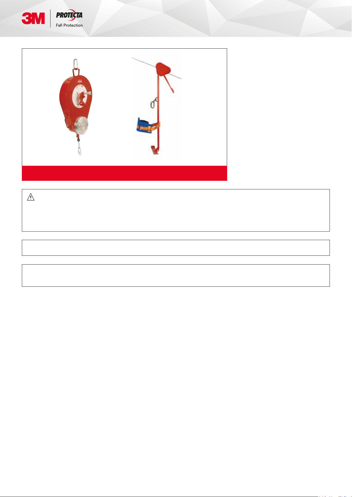
AG300
AG360/I
AG399
Figure 1 - Emergency Descent Device with Manual Retract
Warning: This product is part of an emergency descent system. The user must follow manufacturer’s instructions
for each part of the system. These instructions must be provided to the user of this equipment. The user must read
and understand these instructions before using this equipment. Manufacturer’s instructions must be followed for
proper use and maintenance of this equipment. Alterations or misuse of this equipment, or failure to follow instructions,
may result in serious injury or death.
Important: If you have questions on the use, care, or suitability of this equipment for your application, contact 3M.
Important: Record the product identification information from the ID label in the Inspection and Maintenance Log
in Section 9.0 of this manual.
©3M 2020. All rights reserved.
Page 4
1.0 Application
The Trolmatic™ is designed for emergency personnel escape with automatically controlled speed of descent from an elevated
structure. The Trolmatic™ is only available as a sloped descent model. The Trolmatic™ has to be attached to the carriage AG300
on which the user sits. The carriage is sliding on a guide cable and has a manual brake for docking. See Figure 1.
Warning: The Emergency Descent Device must not be used for fall protection.
1.1 Limitations
The following application limitations must be considered before using this equipment
A. Capacity: This equipment is designed for use by one person with a combined weight (including tools, clothing, etc.)
of 20 kg minimum to 136 kg maximum.
B. Descent: This equipment may not be used for vertical descents. This equipment may only be used as described
in this manual.
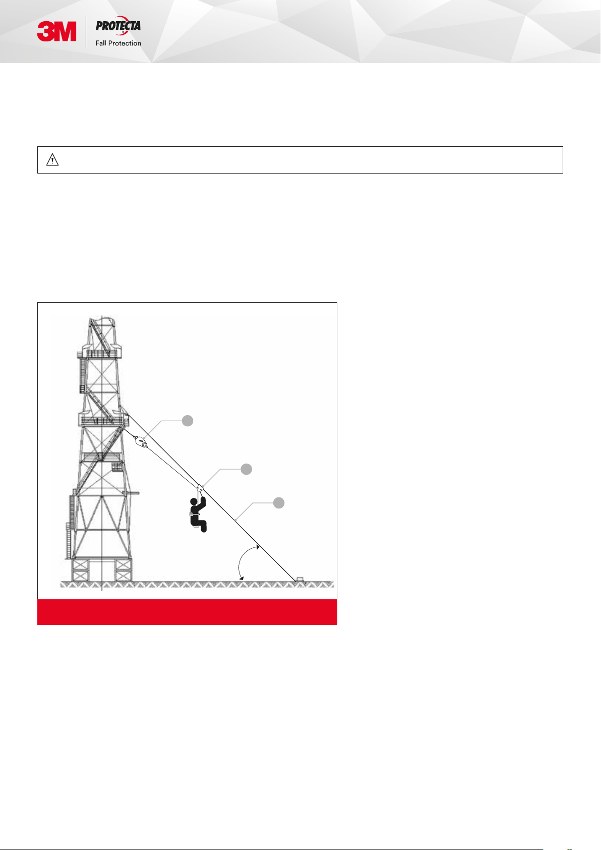
C. Slope Angle of Guide Cable: The guide cable should have an angle of 30° to 45° from the ground (see Figure 2).
A Trolmatic™
B Carriage
C Guide Cable
A
B
C
C
Angle 30°
to 45°
Figure 2 - Slope descent angle
D. Descent Speed The speed at which the user will be lowered when using Trolmatic™ increases with the weight of the user
and with the slope of the guide cable. The maximum speed of descent (inclined speed) is 4 m/s but the usual speed,
with the average angle and average weight, is around 2.5 m/s.
For example, if the angle is 45° and the length of the cable guide is 100 m, the corresponding height is 70 m. An average
speed of 2.5 m/s will lead to descend the inclined 100 m length / 70 m height in 40 seconds.
E. Hazardous Areas: Use of this equipment in hazardous areas may require additional precautions to reduce the possibility
of injury to the user or damage to the equipment. Hazards may include, but are not limited to: high heat, caustic chemicals,
corrosive environments, high voltage power lines, explosive or toxic gases, moving machinery, sharp edges...
F. Training: This equipment is intended to be installed and used by persons trained in its correct application and use.
G. Operating and Storage Temperature: -40°C to 60°C
©3M 2020. All rights reserved.
Page 5

2.0 System Requirements
2.1 Compatibility of Components
The Trolmatic™ is designed to be used with its carriage and a 12 mm diameter cable guide.
Substitutions or replacements made with non-approved components may jeopardize compatibility of equipment,
and may affect the safety and reliability of the complete system.
2.2 Compatibility of Connectors
Connectors (hooks, carabiners, D-rings) must be capable of supporting at least 20 kN. Connectors must be compatible in size,
shape, and strength. Non-compatible connectors may unintentionally disengage (roll-out). Roll-out occurs when interference
between the connector and anchorage connector causes the hook or carabiner gate to unintentionally open and release.
Self-locking snap hooks and carabiners must be used with this system to reduce the possibility of roll-out. Do not use
connectors that will not completely close over the attachment element.
2.3 Anchorage Strength for Emergency Descent Device
The anchorage / structure used to suspend the Trolmatic™ must sustain static loads, applied along the axis of the device, of at
least 12 kN. When more than one Trolmatic™ is attached to an anchorage, the strengths stated above must be multiplied by the
number of descent devices attached to the anchorage. Anchorages used to support a guide cable must be sufficiently strong to
withstand the forces generated in the guide cable by the descent. Recommended anchorage strength (including a safety factor
of 2) for cable guide shall be 18.24 kN (4100 lbs). Guide cable tension should be between 89 daN (200 lbs) and 200 daN (450 lbs).
2.4 Guide Cable and Trolmatic™ Installation
A guide cable must be used with this equipment. See Figure 3. The guide cable installation must be designed by a Qualified
Person. The carriage must be installed as shown, with the braking manual handle pointing to the landing area. The carriage
housing shall not be removed. Insert the cable guide into the carriage trolley at an open end of the cable guide before completing
connection of the cable to the structure. The angle at which the guide cable is secured, as well as the amount of slack in the
guide cable, will affect the descent speed. The guide cable must be installed with sufficient slope and limited slack to ensure the
user will reach the landing area in the event of an emergency descent. The guide cable and the anchorage point must support
the weight of the user in a descent. The guide cable MUST be 12 mm diameter wire rope, galvanized or stainless steel. Bottom
anchorage for the cable guide can be the 3M Pylon Anchor (ref : 7256000, but not CE-certified).
Failure to follow wire specifications will prevent the carriage from sliding and braking correctly and may even cause the carriage
to become stuck during a descent. Connect the quick link of the Trolmatic™ cable end to the lowest bolt of the carriage trolley
(see the closeup of Figure 3) and ensure that the quick link is firmly tightened.
The operation of the Trolmatic™ should be verified by performing a test descent in accordance with section 3.2c.
3M™ can supply guide cable and associated cable clamps and thimbles (see Section 7.0 for component specifications).
©3M 2020. All rights reserved.
Page 6

SS
A
A Guide Cable Top Anchorage
B Trolmatic™ Anchorage
C Tr o l m a t i c™
D Carriage
C
B
E Guide Cable
F Landing Area
G Guide Cable Bottom Anchorage
D
E
Connect the
quick link of
G
F
Angle of
Guide Cable
the Trolmatic™
cable end
to the lowest
bolt of the
carriage trolley
Figure 3 - Installation Configuration
3.0 Installation and Use
3.1 Before Each Use
Before each use of this equipment, carefully inspect it according to section 5.0 of this manual.
3.2 Plan
Plan your emergency escape system and how it will be used before starting your work. Consider all factors that will affect
your safety before, during, and after an escape. Consider the following when planning your system:
A. Anchorage: Select a rigid anchorage point to connect the Trolmatic™ that is capable of supporting at least 12 kN.
See section 2.3.
B. Descent Path And Landing Area Clearance: Your descent path must be unobstructed. The landing area must be clear
of obstructions to permit safe landing of the user. Failure to provide an unobstructed descent path and landing area may
result in serious injury.
©3M 2020. All rights reserved.
Page 7

C. Testing The System: 3M™ recommends performing a test descent using a 75 kg weight. The descent speed should
be uniform and allowed to reach the landing area safely. Remember to log any descent height (including test descents)
in the Descent Log on Page 15 so that the cumulative descent height data is available.
D. Sharp Edges: Avoid using this equipment where system components will be in contact with, or rub against, unprotected
sharp edges. If working with this equipment near sharp edges is unavoidable, cover the sharp edges with heavy pads.
E. After a Descent: See Figure 4 below. To retract the device's line, deploy the articulated part of the handle, and then turn
the handle counter-clockwise. The system is ready for another descent after it is fully retracted.
Deploy the articulated part of the handle. Turn handle counter-clockwise to retract device line.
Caution: When retracting the cable into the
Trolmatic™, the cable should always maintain
tension so that it fits in the handle without any
slack. A minimum of 2 kg tension on the cable is
recommended when turning the handle. Keeping
the AG300 connected to the Trolmatic™ along
the cable guide during cable retraction will
provide the required cable tension.
Figure 4 - Retracting the cable into the Trolmatic™
3.3 Connecting the Trolmatic™ to the Anchorage
Figure 5 illustrates the means of attaching the Emergency Descent Device to the anchorage. See Section 2.0 for compatibility
and anchorage strength requirements.
©3M 2020. All rights reserved.
Page 8

A Structure
A
B Carabiner
C Cable Lanyard
A
A
B
D Anchorage Connector
(Tie-off Adapter)
C
D
B
Figure 5
3.5 Sitting on Trolmatic™
See Figure 6 below. A full body harness is recommended for use with this device. First, disconnect from any fall arrest or restraint
device (lanyard, SRL…) you may be connected on. This is to avoid that starting the evacuation and being stopped by the primary
fall arrest device that you are connected to.
Connect your front D-ring to the captive carabiner of the carriage mast. If you don't have a front D-ring, connect any other
D-ring(s) you may have on your harness to the captive carabiner, like D-rings on the side slings of derrick harnesses, for instance.
Open the belt and close it around you. Then, disconnect yourself of any fall arrest or restraint device (lanyard, SRL…) you may be
connected on. This is to avoid that you start the evacuation and are stopped by your primary fall arrest device that you forgot to
disconnect. Sit down on the seat of the carriage while holding down the manual brake to keep the carriage in place.
Front
D-ring
Figure 6
©3M 2020. All rights reserved.
AG300
Page 9

3.6 Use
Check your descent path and landing area for obstructions before stepping off the structure. The device will allow you to
descend at a rapid rate. Release the manual handle and step out of the structure to descend freely. Pull down on the manual
handle to slow your descent. Do not grasp the guide cable while descending. When you are at the last 20% of your descent,
pull down on the manual handle to slow your descent before reaching ground level. After landing, disconnect your front
D-ring from the trolley, open the belt and exit the landing area.
4.0 Training
It is the responsibility of the user and owner of this equipment to be trained in its correct care and use. The user
4.1
and owner must be aware of the operating characteristics, application limits, and consequences of improper use
of this equipment.
Warning: Training must be conducted without exposing the trainee to a fall hazard. Training should be repeated
on a periodic basis.
5.0 Inspection
A formal inspection of the Trolmatic™ and its connection to the structure shall be made at least every 12 months,
5.1
by a Competent Person. A formal inspection should be completed if the system parameters are changed, such as
after a system is moved or re-rigged its anchorages are moved, the guide cable angle is changed, etc. Extreme
working conditions or an installation that is permanently outside may require increasing the frequency of inspections.
Inspect the Emergency Descent Device according to Sections 5.2 and 5.3. Record inspection results in the Inspection
and Maintenance Log in Section 9.0.
5.2 Inspection Steps
Step 1 . Inspect the device for loose fasteners and bent or damaged parts.
Step 2. Inspect device housing for distortion, cracks, or other damage. Ensure that the top anchorage and crank handle
are not damaged or distorted.
Step 3. The device lifeline must pull out fully. Inspect the wire rope for cuts, kinks, broken wires, corrosion, or severely
worn areas.
Caution: When retracting the cable, it should always be in tension to fit the handle without any slack.
We recommend a minimum of 2 kg of tension on the cable when turning the handle to retract the cable.
Step 4. Device labels must be present and fully legible. See Section 8.0.
Step 5. Inspect for corrosion on the entire device.
Step 6. Inspect connecting hooks, quick link or carabiners for damage, corrosion, and general functionality.
Ste p 7. Inspect the Carriage for excessive wear. The carriage brake handle must move freely along the cable guide.
Inspect the captive carabiner on the carriage mast and ensure that it is in perfect operating condition.
Step 8. Inspect the guide cable. Inspect the wire rope for cuts, kinks, broken wires, corrosion, or severely worn areas.
If the guide cable is damaged do not use the system.
Step 9. Inspect each system component and subsystem according to manufacturer’s instructions.
Step 10. Record inspection results in Section 9.0.
©3M 2020. All rights reserved.
Page 10

5.3 If inspection reveals an unsafe or defective condition, remove the device from service and contact an authorized service
centre for repair. Servicing from an authorized service centre is also mandatory as soon as the cumulative descent height
in the Descent Log reaches 1100 m. For example, after 22 descents of 50 m in height, the Trolmatic™ will need to be
serviced by an authorized service centre, who will at least change the brake.
6.1 Maintenance
Periodically clean the exterior of the Emergency Descent Device with water and mild detergent.
Position the device so excess water can drain out. Clean labels as required. Clean device lifeline with water and mild detergent.
Rinse and thoroughly air dry. Do not force dry with heat. An excessive build-up of dirt, paint, etc., may prevent the lifeline from
retracting back into the device.
6.2 Storage
Store the Emergency Descent Device in a cool, dry and clean environment, as well as out of direct sunlight. Avoid areas where
chemical or organic vapours may be present. Thoroughly inspect the Emergency Descent Device after extended storage.
The Trolmatic™ should always be fully protected against damage and deterioration.
If permanently installed outside or in damp conditions, adequate protection should be provided: cover, shelter, etc...
7.0 Specifications
AG360/I AG399
Useful Length: 60 m 100 m
Unit Weight: 20 kg 27 kg
Material: Metal housing, stainless steel cable
• 5 mm
Cable:
Angle of load-bearing
cable from horizontal:
Speed of descent is
automatically regulated:
Maximum Load: 136 kg
Standards: EN 341 class B
• 7×19 AISI 316 Stainless Steel
• 1400 daN min breaking strength
30° to 45°
Maximum 4 m/s,
average 2.5 m/s
Evacuation Trolley:
3M™ Protecta® Evacuation Trolley - AG300
Weight: 8 kg
Weight Capacity: 136 kg
Carabiner:
Quantity: 1
• Captive Twist-Lock
• Stainless Steel
©3M 2020. All rights reserved.
Page 11

The guide cable and its associated components are available from 3M™, if required by the customer. 3M can also supply the
guide cable and its associated components (thimbles and cable clamp) in kits.
• Kit ref : 8900038 for AG360/I
• Kit ref : 8900037 for AG399.
Cable:
Galvanised Cable - 12 mm - M94120T211
Description: Galvanised cable
Diameter: 12 mm
Cable Length: 108m for AG399, 68m for AG360/I
Construction: 6 × 19
Breaking Strength: 7980 daN
Weight: 53 kg
Thimble:
Thimble for 12 mm Cable - M9612GO071
Description:
Quantity: 2
• Zinc plated thimble
• For 12 mm diameter cable
8.0 Labels
M9612GO071
M540012000
Cable Clamp:
Clamp for 12 mm Cable - M540012000
Description:
Quantity: 6
• Galvanised cable clamp
• For 12 mm diameter cable
M94120T211
Figure 7
©3M 2020. All rights reserved.
Page 12

Inspection and Maintenance Log
Serial Number:
Model Number:
Date Purchased:
Inspection Date Inspection Items Noted Corrective Action Maintenance Performed
Approved by:
Approved by:
Approved by:
Approved by:
Approved by:
Approved by:
Approved by:
Approved by:
Approved by:
Approved by:
Approved by:
Approved by:
Approved by:
Approved by:
©3M 2020. All rights reserved.
Page 13

Inspection and Maintenance Log
Serial Number:
Model Number:
Date Purchased:
Inspection Date Inspection Items Noted Corrective Action Maintenance Performed
Approved by:
Approved by:
Approved by:
Approved by:
Approved by:
Approved by:
Approved by:
Approved by:
Approved by:
Approved by:
Approved by:
Approved by:
Approved by:
Approved by:
©3M 2020. All rights reserved.
Page 14

Inspection and Maintenance Log
Serial Number:
Model Number:
Date Purchased:
Inspection Date Inspection Items Noted Corrective Action Maintenance Performed
Approved by:
Approved by:
Approved by:
Approved by:
Approved by:
Approved by:
Approved by:
Approved by:
Approved by:
Approved by:
Approved by:
Approved by:
Approved by:
Approved by:
©3M 2020. All rights reserved.
Page 15

Descent Log
Serial Number:
Model Number:
Date Purchased: Date of First Use:
Date Descent Height Cumulative Descent Height
©3M 2020. All rights reserved.
 Loading...