

Page 1

C
EXPERIEN
•
GLOBAL
•
Projected Capacitive Near
Field Imaging
SOLUTIONS
Integration Guide
INNOVATIVE
•
EXPERIENCE DEPENDABLE
•
TM
(“NFI”)
GLOBAL
•
INNOVATIVE
•
DEPENDABLE
touch
3M Touch Systems Proprietary Information
Page 2

Copyright
This manual is © 3M 2003. All rights reserved.
Reproduction of the contents of this copyrighted manual in whole or in part, by
any means, electronic or mechanical, for any purpose, without written permission
of 3M Touch Systems, a subsidiary of 3M, is prohibited.
Notice
Important notice to
purchaser
Given the variety of factors that can affect the use and performance of a 3M
Touch Systems Product (the “Product”), including that solid state equipment has
operation characteristics different from electromechanical equipment, some of
which factors are uniquely within User’s knowledge and control, it is essential
that User evaluate the 3M Touch Systems Product and software to determine
whether it is suitable for User’s particular purpose and suitable fo r User’s method
of application. 3M Touch Systems’ statements, engineering/technical
information, and recommendations are provided for User’s convenience, but
their accuracy or completeness is not warran ted. 3M Touch Systems products and
software are not specifically designed for use in medical devices as defined by
United States federal law. 3M Touch Systems products and software should not
be used in such applications without 3M Touch Systems’ express written
consent. User should contact its sales representative if User’s opportunity
involves a medical device application.
Specifications are subject to change without notice. These 3M Touch Systems’
Products and software are warranted to meet their published specifications from
the date of shipment and for the period stated in the specification. 3M Touch
Systems makes no additional warranties, express or implied, including but
not limited to any implied warranties of merchantability or fitness for a
particular purpose.
User is responsible for determining whether the 3M Touch Systems Products and
software are fit for User’s particular purpose and suitable for its method of
production, including intellectual property liability for User's application. If the
Product, software or software media is proven not to have met 3M Touch
Systems’ warranty, then 3M Touch Systems’ sole obligation and User’s and
Purchaser’s exclusive remedy, will be, at 3M Touch Systems’ option, to repair
or replace that Product quantity or software media or to refund its purchase price.
3M Touch Systems has no obligation under 3M Touch Systems’ warranty for any
Product, software or software media that has been modified or damaged through
misuse, accident, neglect, or subsequent manufacturing operations or assemblies
by anyone other than 3M Touch Systems. 3M Touch Systems shall not be liable
in any action against it in any way related to the Products or software for any
loss or damages, whether non-specified direct, indirect, special, incidental or
consequential (including downtime, loss of profits or goodwill) regardless of
the legal theory asserted.
Edition
July 2003. Document Number: 14116 (Rev. 3.0)
Trademarks MicroTouch, Near Field Imaging, and TouchSurround are trademarks of 3M.
Microsoft, Windows, MS-DOS, Windows NT, Windows 2000,
Windows XP, and/or other Microsoft products referenced herein are
either trademarks or registered trademarks of Microsoft Corporation in
the United States and/or other countries. JST is a registered trademark of
J.S.T. Mfg. Co., Ltd.
3M Touch Systems Proprietary Information
Page 3
Intended use
Safety notices
Product Safety Information
The Near Field ImagingTM (NFI) touch screen system is composed of components
for incorporation in electrical or electronic apparatus, equipment or installations.
The NFI touch screen system has been tested to the standards that are cited in the
Appendix of this integration guide to show compatibility for use in products
requiring CE marking under the following directives: the EMC Directive
89/336/EEC, the Low Voltage Directive 73/23/EEC, and the Machinery Directive
89/392/EEC. Caution: Changes or modifications to this equipment not expressly
approved by the manufacturer could void the user’s authority to operate this
equipment.
The manufacturer of the end apparatus will, under their responsibility, comply
with the applicable Directives in design and construction.
WARNING
To reduce the risks associated with electrical shock or mechanical function which,
if not avoided, could result in death or serious injury and/or property damage:
Do not use a power cable that is damaged or frayed or a power plug that is damaged.
Do not use a damaged power supply.
Handle the power supply with care.
Do not service the NFI touch screen system. There no user serviceable parts. Refer all
servicing to qualified service personnel.
Safety labels
CAUTION
To reduce the risks associated with glass breakable which, if not avoided, may result
in minor or moderate cut-related injury:
Handle a touch screen with care to avoid breaking the glass. Be aware of cracked or
broken sensors with sharp edges.
CAUTION
To reduce the risks associated with environmental contamination which, if not
avoided, may result in minor or moderate injury and/or cause property damage:
Dispose of components in accordance with local, state, and federal regulations.
The following safety symbols appear on your NFI touch screen system or
packaging materials:
Symbol Meaning
Warning: Hazardous voltage
Caution: Item is susceptible to electrostatic discharge
(ESD) damage if proper precautions are not taken.
3M Touch Systems Proprietary Information
iii
Page 4

Page 5

Contents
Chapter 1 Overview.......................................................................... 1
Components............................................................................................ 1
Cleaning the touch screen ...................................................................... 2
Chapter 2 Mounting the touch screen............................................ 5
Critical information..................................................... ........................... 5
Steps for mounting an NFI touch screen ................................................ 7
TouchSurround
Chapter 3 Mounting the controller.................................................. 9
Critical information..................................................... ........................... 9
Materials required ................................................................................ 10
Steps for mounting an NFI controller .................................................. 11
Chapter 4 Making connections and resetting the baseline........ 13
Critical information: Connecting the tail .............................................13
Steps for connecting tail to controller.................................................. 14
Critical information: Connecting communications and power ............ 16
Steps for attaching power/communications cable................................17
Critical information: Resetting the baseline.........................................18
Steps for resetting baseline................................................................... 18
Chapter 5 Outdoor applications.................................................... 21
Critical information: Integrating with a metal bezel............................ 21
Critical information: Integrating with a plastic bezel........................... 25
Chapter 6 Troubleshooting............................................................ 27
Strategies..............................................................................................27
Interpreting the controller’s status lights..............................................29
Appendix Standards and certifications........................................ 31
TM
underlay (optional).................................................... 8
3M Touch Systems Proprietary Information
v
Page 6

Page 7
Components
CHAPTER 1
Overview
This chapter provides:
Description of the components of a typical MicroTouch
Capacitive Near Field Imaging
Guidelines for cleaning the touch screen
Terms used in the manual
3M contact information
TM
(“NFI”) touch screen system
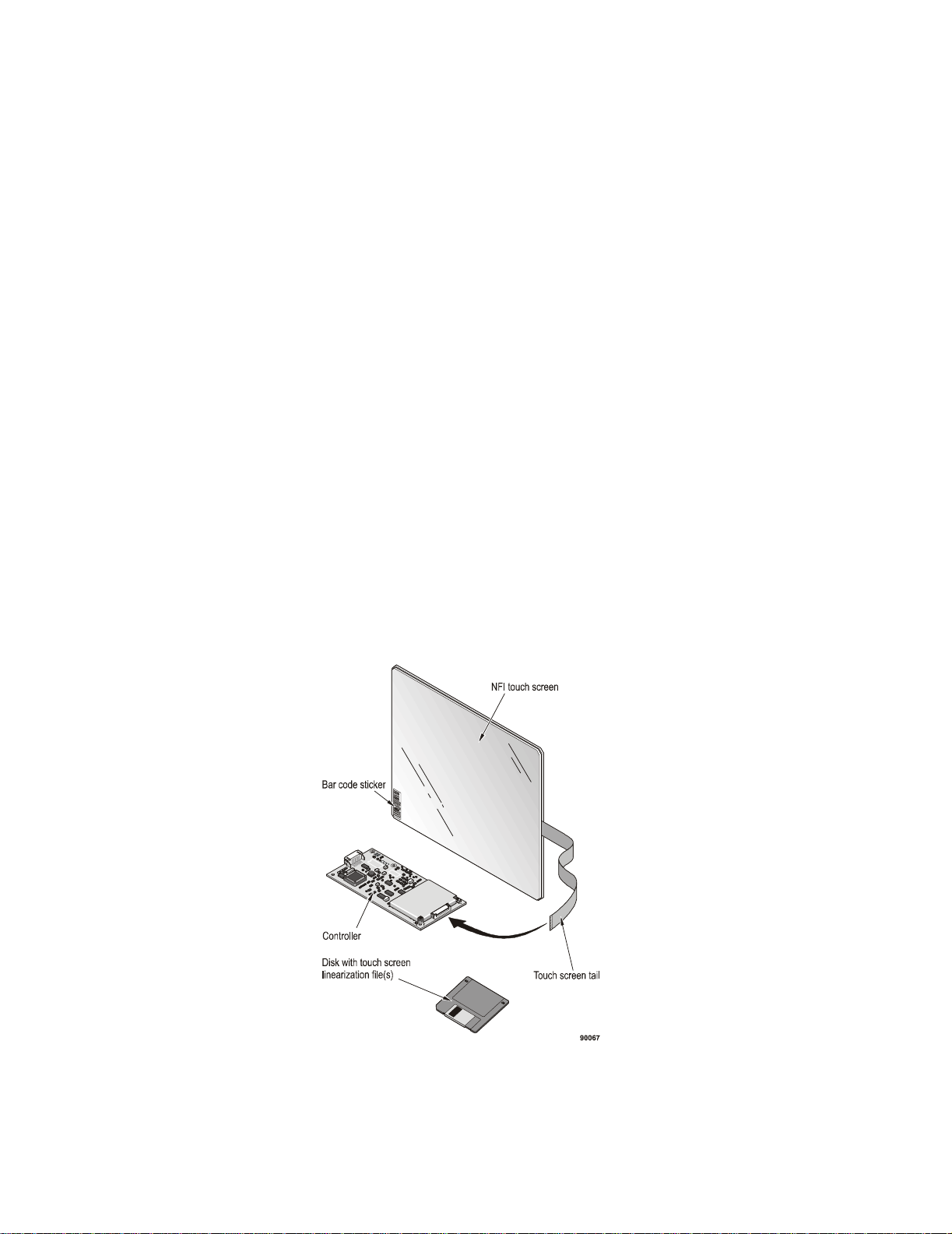
The NFI touch screen system includes the following components:
NFI touch screen and tail. The touch screen is available in different sizes
and can be used with most flat panel displays or adapted to fit flat cathode ray
tube displays. The tail connects the touch screen to the controller.
TM
Projected
3M Touch Systems Proprietary Information
1
Page 8

MicroTouch
TM
Near Field Imaging (NFI)TM Integration Guide
Touch screen controller. The controller decodes signals on the touch
screen. It has connectors for the touch screen tail and for communications/
power.
Floppy disk with linearization file (does not accompany 8.4-inch
screens). Linearization increases the accuracy of an NFI touch screen and
is required for screens larger than 8.4 inches. For details on linearizing, see
“Steps for resetting baseline”, starting on page 18.
Bar code sticker on the touch screen. The serial number provided on
the bar code stickers correspond to the linearization file that is installed (from
the floppy disk) when setting up the touch screen system.
The bar code sticker on the touch screen helps you to recognize which side
of the touch screen is the front side and which is the back side. If you are
looking at the printed side of the bar code sticker, you are looking at the front
of the touch screen.
You will need the serial number if it is ever necessary to:
Re-install the linearization file.
Contact 3M Touch Systems customer service.
Cleaning the touch screen
Follow these guidelines for cleaning the NFI touch screen:
To clean the touch screen’s back side, blow away dust with pressurized air.
To clean the front of the touch screen, use cleaning solutions and cloths
designed for cleaning coated optical glass (e.g., isopropyl alcohol and water
50:50 solution). Do not use any chemical that corrodes glass. Follow cleaner
manufacturer’s material safety data sheet (MSDS) and follow all instructions
and recommendations on product label.
Apply the cleaner with a soft, lint-free cloth. Avoid using gritty cloths.
Apply the cleaning liquid to the cloth, not directly to the screen.
Terms
These terms appear in this manual and may be unfamiliar.
This term Refers to
Baseline An electronic ‘picture’ of the touch screen and its immediate
Display area The part of the touch screen that is positioned over the product’s
Continuous frame Gasket material that has no ends.
Metallized bezel Plastic bezel with conductive material applied to its interior.
Near Field Imaging
(NFI)
Opaque area A narrow border around the perimeter of the touch screen
Touch sensitive area Part of touch screen’s viewing area that will register a touch.
Viewing area The part of the touch screen that is within the opaque area.
3M Touch Systems Proprietary Information
surroundings. Baseline must be reset after any physical or
mechanical change is made to the NFI touch screen integration
or system. With an up-to-date baseline, the touch screen system
performs more accurately and efficiently.
display. Touches in the display area emulate the movements
and actions of a mouse.
A touch screen that uses a proprietary imaging technique to
generate a precise profile of a touch from changes in the
electrostatic field near to the point of contact.
(usually silver-grey or black) that does not register touches.
Sometimes called “the guard”.
2
Page 9

3M Touch Systems support services
3M Touch Systems provides extensive support services through our website and
technical support organization. Visit the 3M Touch Systems website at
www.3Mtouch.com
obtain regularly updated technical documentation on 3M Touch Systems
products, and learn more about our company.
Whenever you contact Technical Support, please provide the following
information:
Part number and serial number
Current driver version
Operating system used
Information on additional peripherals
Technical Support is available Monday through Friday 8:00 a.m. to 8:00 p.m.
US Eastern Standard Time, 9:00 a.m. to 5:00 p.m. throug hout Europe. There is
limited service on Saturdays and Sundays.
You can contact 3M Touch Systems Technical Support (US only — Eastern
Standard Time) by calling the hot line or sending a fax:
Technical Support Hot Line: 978-659-9200
Technical Support Fax: 978-659-9400
Toll Free: 1-866-407-6666
Email: US-TS-techsupport@mmm.com
, where you can download touch screen software and drivers,
Overview
3M Touch Systems worldwide offices
All offices can be reached through the website: www.3Mtouch.com.
Country Telephone
United States 978-659-9000
Australia 61-3-9582-4799
Canada 604-521-3962
France 33-(1)-30-31-68-32
Germany 49-(0)-2131-14-4003
Hong Kong/China 852-2333-6138
Italy 39-(0)-39-230-2230
Japan 81-(4)-4811-1133
Korea 822-552-3198
Singapore 65-6450-8851
Spain 34-934-15-6285
Taiwan 886-2-2704-9011
3M Touch Systems Proprietary Information
3
Page 10

Page 11

CHAPTER 2
Mounting the touch screen
This chapter outlines:
Critical information to help you mount the touch screen successfully.
Step-by-step mounting instructions.
Basic information on the TouchSurround
If you are integrating the touch screen in an outdoor application:
Using a metal bezel, see additional instructions starting on page 21.
Using a plastic bezel, see additional instructions on page 25.
Critical information
Prevent interference
Mount the touch screen as far away as possible from:
Components (such as radios) that generate a signal in the 50 kHz to 60 kHz
AC sources and backlight inverters (unless there is intervening grounded
TM
range (unless they are adequately shielded).
metal work or shielding).
underlay.
Observe minimum mounting clearances
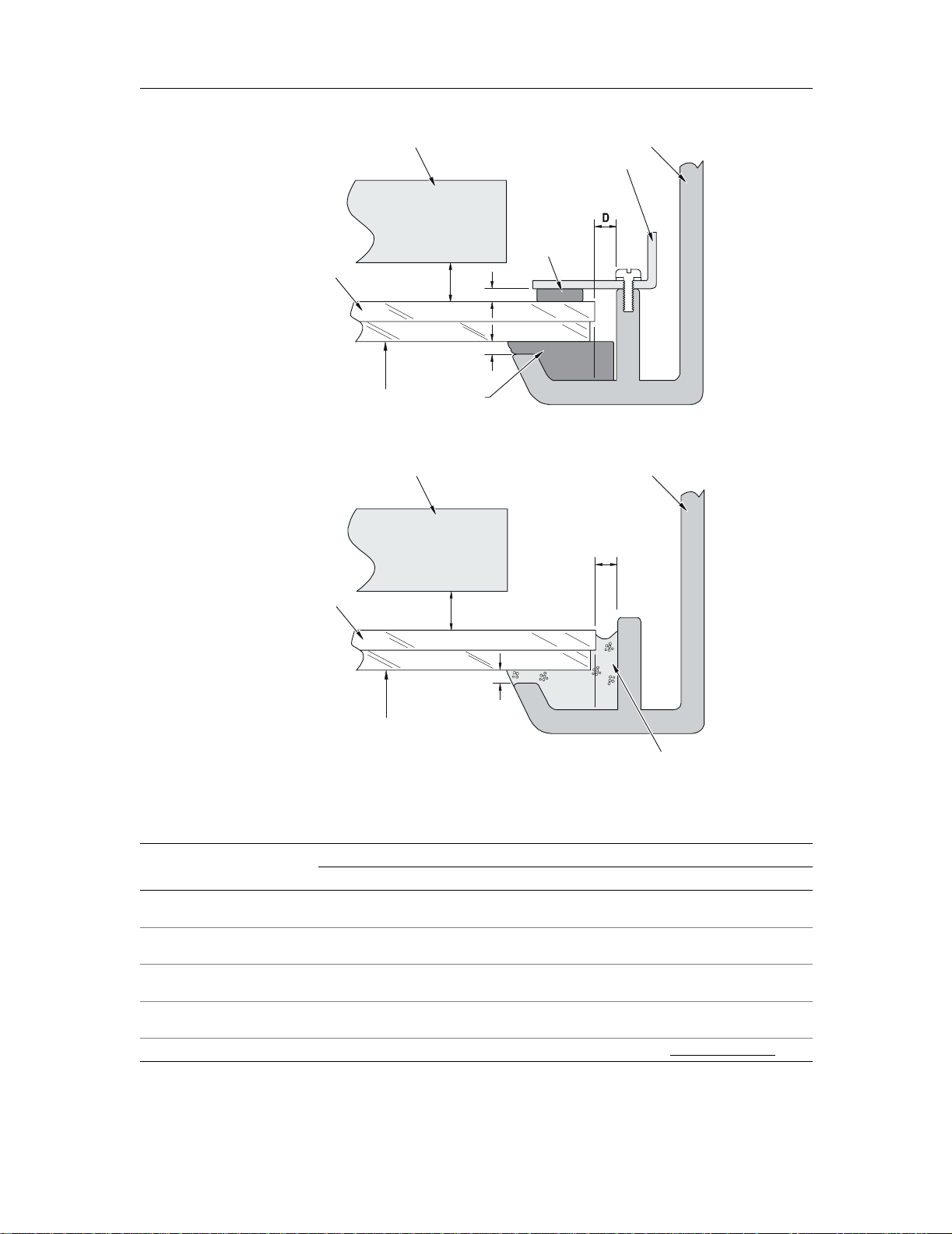
Minimum mounting clearances are shown in Table A to help in tegrators make
mounting decisions that will minimize capacitive loading on the touch screen and
tail. Read Table A while referring to Figure 1 or Figure 2 (whichever figure
applies to your mounting materials).
3M Touch Systems Proprietary Information
5
Page 12
MicroTouchTM Near Field Imaging (NFI)
TM
Integration Guide
Display
Metal bezel
Metal clamp
Spacer (Non-
NFI touch
screen
C
conductive)
B
A
Front
Gasket (Non-
conductive)
Figure 1: Mounting (using metal bezel) with metal clamp (Top View)
Metal bezel
D
NFI touch
screen
Display
C
A
Front
Adhesive
Figure 2: Mounting (using metal bezel) with adhesive (Top View)
T able A: Minimum mounting clearances (Use this table with Figure 1
Screen size
8.4" 10.4" 12.1" 15.0" 18.1"
A
— Front of touch screen to
inside lip of bezel
B
— Front of clamp to back of
touch screen
C
— Display to back of touch
screen
D
— Side of bezel to edge of
touch screen
Viewing area & bezel opening: See NFI touch screen drawings on 3M Touch Systems website: www.3Mtouch.com
0.020"
(0.5 mm)
0.020"
(0.5 mm)
0.060"
(1.5 mm)
0.030"
(0.8 mm)
0.020"
(0.5 mm)
0.030"
(0.8 mm)
0.070"
(1.8 mm)
0.030"
(0.8 mm)
0.020"
(0.5 mm)
0.035"
(0.9 mm)
0.080"
(2.0 mm)
0.030"
(0.8 mm)
or Figure 2)
0.020”
(0.5 mm)
0.045"
(1.1 mm)
0.100"
(2.5 mm)
0.030"
(0.8 mm)
0.030"
(0.8 mm)
0.060"
(1.5 mm)
0.120"
(3.1 mm)
0.030"
(0.8 mm)
3M Touch Systems Proprietary Information
6
Page 13

Mounting the touch screen
Observe best practices for different mounting methods
The touch screen can be integrated with either clamps or adhesive:
If mounting with a clamp
Use gaskets between the sensor and clamp and between the sensor and bezel.
Choose gaskets with the following properties:
Non-conductive (with little or, preferably, no carbon content) to seal
gap A in Table A.
Low compression set.
If foam gaskets are required, they should be water resistant (closed-cell and
non-porous). Many neoprene and silicone gaskets have these properties.
Choose non-conductive spacers to achieve the minimum clearances for gap B
(see Table A), or use an air gap.
If you are mounting the NFI touch screen outdoors, refer to Chapter 5.
If mounting with adhesive
Choose adhesives with the following properties:
Non-acidic, neutral pH adhesive such as room temperature vulcanizing
(RTV) adhesives.
You can also integrate the NFI touch screen with closed cell foam with
adhesive on both sides.
Warranty note: If you use an adhesive to mount an NFI touch screen into a bezel,
the touch screen must be detached from the bezel and adhesive to be returned to
3M Touch Systems under warranty.
If your application requires an exceptional seal to prevent moisture or dust
entering the bezel, please see instructions for outdoor applications in Chapter 5.
Steps for mounting an NFI touch screen
For specific information on mounting a touch screen outdoors, refer to Chapter 5.
1. On a protected surface, line up the gasketing or adhesive with the bezel.
Do not allow the bezel and gasket to encroach on any side of the touch
screen’s viewing area by more than 0.020 inches (0.5 mm). Encroaching by
more than that amount may adversely affect the performance of the touch
screen.
2. Check that the minimum clearances have been met for gap A (Tabl e A on
page 6).
3. Position the NFI touch screen on top of the gasketing or adhesive.
4. If you use clamps to integrate the touch screen, then spacers are required to
push the touch screen against the gasket. Align the spacers and install the
clamps and screws according to the instructions provided by the bezel
manufacturer.
5. If the NFI touch screen is integrated with adhesive, follow the instructions
provided by the manufacturer to ensure that the bonding is set correctly.
3M Touch Systems Proprietary Information
7
Page 14

MicroTouchTM Near Field Imaging (NFI)
TM
Integration Guide
TouchSurroundTM underlay (optional)
A TouchSurround underlay can be fitted behind an NFI touch screen (when the
touch screen is larger than the display) to allow part of the touch screen to be used
to define keys such as the ones on a keyboard (Figure 3).
Figure 3: TouchSurround underlay
3M Touch Systems Proprietary Information
8
Page 15

CHAPTER 3
Mounting the controller
This chapter provides the following information:
Critical information about mounting the controller. Following the
Materials required
Step-by-step instructions
Critical information
Ground properly
There is only one correct grounding location on the controller (see
Extend the grounded metal surface (to which the controller is mounted) by
If the controller is above a grounded continuous metal surface, place it
recommendations in this section will help ensure you are successful in
mounting the controller
“Grounding Hole” in Figure 4 on page 10) and it must be connected for the
controller to operate correctly.
at least 0.25 inches (6.4 mm) beyond the outli ne of the controller.
no less than 0.10 inches (2.5 mm) and no more than 0.30 inches (7.6 mm)
from that surface.
Avoid contact with shields
Make sure that nothing touches the top or bottom shields (Figure 5 on
page 11).
Prevent interference
Minimize electromagnetic interference. Specifically, make sure that the
controller is:
Away from sources of noise (e.g., transformers, AC sources, backlight
inverters, and high-voltage switching noise).
As far away as possible from components that generate a signal in the
50 kHz to 60 kHz range (unless th ey are adequately shielded).
(For guidelines on electrically connecting portable applications, contact “3M
Touch Systems support services” on page 3.)
3M Touch Systems Proprietary Information
9
Page 16

MicroTouchTM Near Field Imaging (NFI)TM Integration Guide
Materials required
To mount the NFI controller, the following materials are required:
Screwdriver appropriate for No.4 Phillips or M3 screws
4 No. 4 Phillips (or M3) pan-head screws
Make sure the screw heads are small enough that they do not touch the
circuitry surrounding them (see Figure 5 on page 11 and Figure 6 on
page 11).
4 No. 4 (or M3) compression washers
If compression washers are unavailable, star washers, single coil washers or
shakeproof washers may be substituted. Make sure the washers are small
enough that they do not touch the circuitry surrounding them (see Figure 5
on page 11 and Figure 6 on page 11).
1 grounding wrist strap
Shield
5.50" (139.7 mm)
0.2" (5.1 mm)0.2" (5.1 mm)
0.2"
(5.1 mm)
2.75"
(69.9 mm)
0.2" (5.1 mm)
0.2"
(5.1 mm)
Do not touch shields with grounding wire.
They are not grounded. If shields touch grounded
metal work, the controller will malfunction.
Shield
Shield
0.125" (3.2 mm) Dia.
all holes
3.77" (95.8 mm)
5.10" (129.5 mm)
Plan view
Side view
0.24"
(6.1 mm)
1.53" (38.9 mm)
Overall height
0.32" (8.1 mm)
Figure 4: Dimensions of controller
Critical
There is only one grounding location and it must be connected for the controller to operate
correctly (See Figure 5 on page 11).
0.2"
(5.1 mm)
2.35"
(59.7 mm)
Grounding
hole
3M Touch Systems Proprietary Information
10
Page 17

Steps for mounting an NFI controller
1. The components on the NFI controller are sensitive to damage from
electrostatic discharge (ESD). To prevent damage from ESD, put on a
grounding strap, connect to ground, and touch a grounded object to
discharge any built-up static.
2. Locate the mounting holes on the NFI controller (Figure 5).
Mounting the controller
Figure 5: Controller’s mounting holes, grounding/mounting hole
3. Insert the screws and washers into the mounting holes. T ake care to not short
out the surrounding circuitry with either the screws or washers. Tighten the
screws so that the controller is firmly in place and the washers will not
move.
Do not use metal fasteners that could touch and
short out the surrounding circuitry or plated holes.
Figure 6: Mounting controller
3M Touch Systems Proprietary Information
11
90075_2003
Page 18

MicroTouchTM Near Field Imaging (NFI)TM Integration Guide
4. Ground the controller. 3M Touch Systems recommends grounding the
controller using a ground screw through a metal stand off (Figure 7). If the
stand off is not grounded, attach a grounding cable (Figure 8).
Metal grounding
To achieve grounding, useonly
grounding screw hole.
Grounding screw hole
Grounded stand off
screw
Metal compression
washer
Controller
90076_2003_a
Figure 7: Grounding controller using stand off
Metal grounding
screw
Metal compression
washer
Grounding cable
To achieve grounding, useonly
the grounding screw hole.
Grounding screw hole
Controller
Figure 8: Grounding controller using cable
5.
Make sure that the grounding cable, compression washer and metal
grounding screw do not touch or short out the surrounding circuitry.
90077_2003
3M Touch Systems Proprietary Information
12
Page 19

CHAPTER 4
Making connections and resetting the
baseline
This chapter provides the following information:
Critical information and steps for connecting the NFI touch screen tail.
Critical information and steps for connecting power/communications.
Critical information and steps for resetting the baseline.
Critical information: Connecting the tail
The touch screen tail connects the touch screen to the controller. The following
tail connection practices are essential for achieving a successful integration.
Prevent interference
Position the tail and controller away from:
Components that gene rate a signal in the 50 kHz to 60 kHz range (unless
components are adequately shielded).
AC sources (such as backlight inverters) and high-voltage switching
noise. If this is not possible, make sure the AC or noise source is
appropriately shielded and grounded.
Conductive surfaces — at least 0.10 inches (2.5 mm) away.
If the tail must run along a large conductive metal surface, keep it at least
0.10 inches (2.5 mm) from the surface and make sure that it cannot move
(e.g., by using an adhesive foam spacer).
Bending and position the tail properly
Do not bend the tail past a radius of 0.100 inches (2.5 mm). The tail can be
damaged and the touch screen may not operate correctly if it is severely
creased.
To provide extra protection for the touch screen tail, consider wrapping the
entire tail in an insulator (i.e. foam or nylon).
If the tail wraps around a sharp edge in your product, use an insulator on
the edge of the surface to prevent chafing.
3M Touch Systems Proprietary Information
13
Page 20

MicroTouchTM Near Field Imaging (NFI)TM Integration Guide
At least 0.100" (2.5 mm)
between tail and a surface
that is conductive
Use insulator to protect tail
wrapped around sharp edge
Figure 9: Using an insulator if tail wraps around a sharp edge
Steps for connecting tail to controller
To connect the touch screen tail to the controller:
1. Put on a grounding strap, connect to ground, and touch a grounded object to
discharge any built-up static on your body.
2. Place the touch screen on a non-conductive surface (e.g., cardboard). Make
sure the side of the touch screen with the bar code visible is face up.
3. Remove the controller from its ESD-protected plastic envelope. Make sure
that the major electronic components are face up.
4. Use two fingers to gently pull out the retaining clip so that it protrudes
slightly from the controller’s connector. To protect the retaining clip from
damage, do not remove it completely (Figure 10).
Touch screen tail
Bend radius 0.100"
(2.5 mm)
90085
Pull out clip just enough so it
protrudes slightly from connector
90010_2003
Figure 10: Pulling out retaining clip from touch sc ree n co nn e cto r on
controller
3M Touch Systems Proprietary Information
14
Page 21

Making connections and resetting the baseline
5. Orient the end of the touch screen tail so that the shiny (conductive) side
faces you (Figure 11).
Conductive side
Figure 11: Orientin g tail
6. Attach the tail by inserting it gently — with the shiny side up — between the
retaining clip and the connector on the controller. Make sure that the tail is
seated straight and fully inserted in the connector (Figure 12).
Touch screen
tail
Connector
Retaining
clip
Conductive side
90079_2003
Figure 12: Attach in g tail
With a finger on each side of the retaining clip, push it until the retaining clip
7.
fits snugly inside the connector (Figur e 13).
Figure 13: Pushing retaining clip into connector
3M Touch Systems Proprietary Information
15
Page 22

MicroTouchTM Near Field Imaging (NFI)TM Integration Guide
Critical information: Connecting communications and power
Check power supply
Before connecting the NFI controller to the host computer’s COM port and power
source, make sure that:
The NFI controller has a regulated DC power supply of 5V ±5 percent,
capable of providing at least 300 mA.
There is at least 4.75 VDC measured on the NFI controller (otherwise it will
remain in reset mode).
For the NFI controller, 3M Touch Systems reco mm ends using a Class 2
power source according to the standards set by the U.S. National Electrical
Code or the Canadian Electrical Code. Using a power source other than
Class 2 may require additional safety certifications for your product.
If the power supply is noisy, it may be necessary to isolate the power and other
cables by using a ferrite core.
Use an RS-232 power/communications cable
To connect the controller, a standard RS-232 power/communications cable is
required:
An NFI RS-232 power/communications cable (which comes with stripped
flying leads) is available from 3M Touch Systems. This cable can then be
completed to fit the power supply and communications requirements of your
application. To purchase this cable contact “3M Touch Systems support
services” on page 3.
Alternatively, you may choose to make a cable using the information located
in Table B and Table C.
Making an RS-232 power/communications cable
Table B provides information on recommended components for the cable.
Table B: Components for RS-232 power/communications cable
Component Manufacturer Part number
Power and communications connector on the
controller
Recommended mating connector housing JST* PHR–8
Recommended mating connector contacts JST* SPH–002T–P0.5S
*For information on JST products, refer to www.jst.com
JST* S08B–PH–SM3–TB
.
3M Touch Systems Proprietary Information
16
Page 23

Making connections and resetting the baseline
Table C provides information on the pin out for the controller and cable.
Table C: Pin out for RS-232 power/communications cable
Controller
Pin
1 Unused Unused Unused -2 SGND RS-232 signal ground -- 5 - DB9 female
3 RXD RS-232 receive IN 3 - DB9 female
4 TXD RS-232 transmit OUT 2 - DB9 female
5 _RST Reset— active low TTL
6 Gnd Common -- User-provided
7 Gnd Common -- User-provided
8 +5VDC + 5V DC IN User-provided
Controller Function Controller
In/Out
IN If needed, user
logic level (leave
unconnected if not used)
Steps for attaching power/communications cable
To attach the RS-232 power/communications cable to the controller:
1. Locate the power/communications connector (Figure 14).
Connector Pin
Connector
Connector
Connector
defined control
power supply
power supply
power supply
Power/communications
connector
90009
Figure 14: Power/communications connec to r on controller
3M Touch Systems Proprietary Information
17
Page 24

MicroTouchTM Near Field Imaging (NFI)TM Integration Guide
2. Orient the end of the cable so that it is aligned with the connector on the
controller. Pin 1 of the RS-232 power/communications cable lines up with
Pin 1 of the connector on the controller (Figure 15).
Pin 1
Pin 8
Figure 15: Attach ing power/communications ca ble
3. Insert the cable fully into the connector. Secure the cable so that it cannot
move.
4. Attach the remainder of the cable as appropriate for the specifications of
your application.
Critical information: Resetting the baseline
The baseline must be reset after any physical or mechanical change is made to the
NFI touch screen system (e.g., after integrating in a bezel or display assembly,
adding or replacing gaskets, mounting or re-mounting the unit).
When you reset the baseline, an electronic ‘picture’ is taken of the touch screen
and its immediate surroundings. To ensure that the baseline is reset successfully,
make sure that nothing is touching the screen, bezel, or controller during the
baselining process.
Steps for resetting baseline
There are different procedures for resetting the baseline, depending on which NFI
touch screen driver you are using. Follow the instructions below that are
appropriate for your touch screen driver. After the NFI touch screen is fully
integrated see the Near Field Imaging
information on setting up and installing the NFI software.
TM
(NFI) Software User’s Guide for
90015_2003
Critical
If a message appears indicating that baselining was not successful, check to make sure
that nothing is touching the touch screen, bezel, or controller and that nothing conductive
is touching the tail, then try resetting the baseline again.
3M Touch Systems Proprietary Information
18
Page 25

Making connections and resetting the baseline
Windows XP/2000 drivers
1. From the Windows desktop, select Start » Programs » Touch » NFI Setup
Utility.
2. Select NFI Setup Wizard.
3. Select Continue.
4. Select Start to begin resetting the baseline. Do not touch or allow other
things to touch the touch screen, bezel, or controller during baselining.
5. Select OK to acknowledge that baselining was successful.
6. Select Skip (linearization data is not required to reset the baseline).
7. Select Start to begin re-aligning the touch screen (the touch screen must be
re-aligned after the baseline is reset).
When aligning, be sure you are directly in front of the touch screen. Use a
finger or alignment tool to align the touch screen. An alignment tool
produces a more accurate alignment.
8. Select OK if you are satisfied with the new touch screen alignment.
9. Select Exit when the NFI Setup Utility dialog box reappears.
10. Power cycle the controller.
Windows NT/9X drivers
1. From the Windows desktop, select Start » Programs » Touch Screen
Utilities » NFI Setup Wizard.
2. Select Next to start the Wizard.
3. Select Next and then select Start to begin setting the baseline.
4. Select Next if baselining was successful.
5. Select Next.
6. Select Cancel (linearization data is not required to reset the baseline).
7. Select No to confirm that you do not want to download linearization data but
that you want linearization to continue to function on the NFI touch screen
system.
8. Select Next to proceed with touch screen alignment (the touch screen must
be re-aligned after the baseline is reset).
9. Select OK and then follow the on-screen instructions to align the touch
screen.
Note: If your touch screen has defined TouchSurround
that the Align TouchSurround check box is selected before selecting OK.
T o cancel alignment without changes, press ESC at any time. When aligning,
be sure you are directly in front of the touch screen. Use a finger or
alignment tool to align the touch screen. An alignment tool produces a more
accurate alignment.
TM
buttons, be sure
10. Select Done when alignment is finished and you are satisfied with the
alignment.
11. Power cycle the controller.
3M Touch Systems Proprietary Information
19
Page 26

MicroTouchTM Near Field Imaging (NFI)TM Integration Guide
For Windows 3.1 and MS-DOS drivers
If you are using Windows 3.1, exit to MS-DOS.
1. At the MS-DOS prompt type CD \TOUCH (note that there is a space
after CD).
2. Type NSD to start the NFI Setup and Diagnostic utility.
3. Type 1 and then press Enter.
4. If you are using a COM port other than COM 1, follow the on-screen
instructions to change the COM setting.
5. Select Y and press Enter to skip downloading linearization data
(linearization data is not required to reset the baseline).
6. Select Y and then press Enter to begin resetting the baseline. A message will
appear on the screen after the baseline has been successfully reset.
7. The touch screen must be re-aligned after the baseline is reset.
8. At the MS-DOS prompt, type ECAL and then press Enter.
Follow the on-screen instructions to re-align the touch screen.
When aligning, be sure you are directly in front of the touch screen. Use a
finger or alignment tool to align the touch screen. An alignment tool
produces a more accurate alignment.
9. After the touch screen is re-aligned, if your touch screen has defined
TM
TouchSurround
buttons, you must also re-align the TouchSurround
underlay . To do so, follow these steps:
At the MS-DOS prompt, type ECAL /S (note that there is a space
after ECAL) and then press Enter.
Follow the on-screen instructions to complete the TouchSurround underlay
alignment.
10. Power cycle the controller.
3M Touch Systems Proprietary Information
20
Page 27

CHAPTER 5
Outdoor applications
This chapter provides:
Critical information on how to integrate the NFI touch screen system
outdoors using a metal bezel. Information in the first section of this chapter
(“Critical information: Integrating with a metal bezel” ) assumes that your
bezel is metal.
Critical information for metalizing a plastic bezel. Although most of this
chapter assumes that a metal bezel is being used, 3M Touch Systems
recommends that, for outdoor applications, a metalized plastic bezel be used
whenever possible.
This chapter assumes that you have already read information on mounting the
touch screen (Chapter 2), mounting the controller (Chapter 3), and making
connections and resetting the baseline (Chapter 4).
If you are integrating outdoors and information in this chapter conflicts with
information elsewhere in this manual, this chapter takes precedence.
Critical information: Integrating with a metal bezel
Prevent electrical shorts
The top priority when integrating an NFI touch screen into an outdoor
application, is to prevent water from shorting the 55khz signal on the touch screen
to the grounded bezel. This is especially important when using a metal bezel to
integrate outdoors (as is assumed in this section of the chapter).
If water is allowed to pool in the area between the bezel edge and the sensor, it can
become an electrical bridge and electrically short the touch screen system and/or
generate false touches. Salt water has an even greater potential to cause this sort
of problem.
To help prevent electrical shorts:
Observe minimum mounting clearances. Minimum mounting clearances
for metal bezels are shown in Table D to help integrators make mounting
decisions that will minimize capacitive loading on the touch screen and tail.
Read Table D while referring to Figure 16 or Figure 17 (whichever figure
applies to your mounting materials).
3M Touch Systems Proprietary Information
21
Page 28

MicroTouchTM Near Field Imaging (NFI)TM Integration Guide
Metal bezel
D
Adhesive
NFI touch
screen
Display
C
A
Front
Figure 16: Mounting (using metal bezel) with metal clamp (Top View)
Display
Metal bezel
D
NFI touch
screen
C
A
Front
Figure 17: Mounting (using metal bezel) with adhesive (Top View)
T able D: Minimum mounting clearances
Screen size
8.4" 10.4" 12.1" 15.0" 18.1"
A
— Front of touch screen to
inside lip of bezel
B
— Front of clamp to back of
touch screen
C
— Display to back of touch
screen
D
— Side of bezel to edge of
touch screen
Viewing area & bezel opening: See NFI touch screen drawings on 3M Touch Systems website: www.3Mtouch.com
0.020"
(0.5 mm)
0.020"
(0.5 mm)
0.060"
(1.5 mm)
0.030"
(0.8 mm)
0.020"
(0.5 mm)
0.030"
(0.8 mm)
0.070"
(1.8 mm)
0.030"
(0.8 mm)
0.020"
(0.5 mm)
0.035"
(0.9 mm)
0.080"
(2.0 mm)
0.030"
(0.8 mm)
0.020”
(0.5 mm)
0.045"
(1.1 mm)
0.100"
(2.5 mm)
0.030"
(0.8 mm)
0.030"
(0.8 mm)
0.060"
(1.5 mm)
0.120"
(3.1 mm)
0.030"
(0.8 mm)
3M Touch Systems Proprietary Information
22
Page 29

Outdoor applications
If mounting outdoors with a clamp:
Use only foam closed-cell gaskets that do not absorb moisture and that
have a low compression set.
Use spacers to push the touch screen against the gasket. Align the spacers
and install the clamps and screws according to the instructions provided
by the manufacturer.
If mounting outdoors with adhesive, follow the instructions provided by the
adhesive manufacturer to ensure that the bonding is set correctly. 3M
Touch Systems recommends:
Use a non-acidic variety of RTV (room temperature vulcanizing) or
silicone adhesives. Using a non-acidic adhesive helps prevent corrosion.
If you choose to use foam adhesive, it is preferab le to purchase it in a
large square and then cut it to create a continuous frame that fits your
touch screen and bezel. This method is the best way of creating a
moisture-resistant seal when using this type of adhesive.
Do not use PSAs (pressure-sensitive adhesives) for outdoor applications.
PSAs will eventually deteriorate and admit water between the touch
screen and bezel (and potentially short out the touch screen).
Design and position the NFI touch screen as described below:
For best results, design the bezel ledge so that it slopes away from the
touch screen exposing the gasket and opaque area of the touch screen
(Figure 18). By recessing the bezel from the touch screen, water will be
shed easier.
Touch screen
Bezel
Gasket (stands proud of bezel)
Expose opaque area
as much as possible
Figure 18: Recess bezel to expose gasket
3M Touch Systems Proprietary Information
23
Page 30

MicroTouchTM Near Field Imaging (NFI)TM Integration Guide
Do not allow the bezel and gasket to encroach into the touch screen’s
viewing area. It is critical to expose the opaque area on the perimeter of
the touch screen by enlarging the bezel opening as much as possible —
especially along the bottom and sides of the touch screen — so that the
bezel is as far as possible from the touch screen’s viewing area
(Figure 18).
A good rule of thumb is to expose the opaque area by at least the height
of the water that you anticipate might collect on the ledge of the bezel.
You will need to strike a balance between exposing the opaque area
and ensuring an adequate seal for your application. If the bezel opening
is to large, the gasket may be to thin and the seal might be compromised.
Mount the touch screen system (bezel and touch screen) as vertically as
possible.
To give the touch screen extra protection from precipitation and direct
sunlight design and install a canopy over the touch screen. Direct sunlight
can cause the display to become very hot and may reduce the display's life
expectancy.
To help prevent moisture from collecting on the unit, you may want to
consider designing and creating a durable plastic "lip" to adhere to the
opaque area of the touch screen (see Figure 19 for an example). Note
Although adding a durable plastic lip may help prevent water from
pooling on the bezel ledge, incorporating a plastic part is not appropriate
for all applications (e.g., environmental conditions may cause the plastic
to crack or melt).
Example of a durable
plastic "lip"
Figure 19: Possible setup of plastic “lip”
Warranty note
: If you use an adhesive to mount an NFI touch screen into a bezel,
the touch screen must be detached from the bezel and adhesive to be returned to
3M Touch Systems under warranty.
3M Touch Systems Proprietary Information
24
Page 31

Critical information: Integrating with a plastic bezel
Before mounting an NFI touch screen in a plastic bezel, metalize the bezel using
conductive paint with conductivity of 10 ohms/square or less.
Leave an unpainted strip that is about 1/8-inch wide between the edge of
the bezel and the conductive paint. This helps prevent water from reaching the
metallized (painted) area (Figure 20, Figure 21, and Figure 22).
Apply the grounded metallization past the edge of the touch screen. This
prevents interference with the touch screen from objects near or touching the
bezel.
Touch screen
Gasket
Outdoor applications
Grounded metallization
Bezel
Front
Figure 20: Metallizing a plastic bezel
Ground the metallized area through screws that attach to the bezel.
Observe minimum mounting clearances (Table E on page 26). Note: The
Conductive paint on bezel
(for grounded metallization)
must extend past the edge
of touch screen
mounting clearances in Table E apply whether integrating into a plastic or
metal bezel.
3M Touch Systems Proprietary Information
25
Page 32

MicroTouchTM Near Field Imaging (NFI)TM Integration Guide
Plastic bezel
D
Adhesive
Grounded metallization
NFI touch
screen
Display
Metallization extends
beyond touch screen
C
A
Front
Recess metallization from
edge of plastic bezel
Figure 21: Mounting (using plastic bezel) with metal clamp (Top View)
Plastic bezel
D
NFI touch
screen
Display
Metallization extends
beyond touch screen
C
A
Front
Recess metallization from
edge of plastic bezel
Grounded metallization
Adhesive
Figure 22: Mounting (using plastic bezel) wit h ad he si v e (Top View)
Table E: Minimum mounting clearances
Screen size
8.4" 10.4" 12.1" 15.0" 18.1"
A
— Front of touch screen to
inside lip of bezel
B
— Front of clamp to back of
touch screen
C
— Display to back of touch
screen
D
— Side of bezel to edge of
touch screen
Viewing area & bezel opening: See NFI touch screen drawings on 3M Touch Systems website: www.3Mtouch.com
0.020"
(0.5 mm)
0.020"
(0.5 mm)
0.060"
(1.5 mm)
0.030"
(0.8 mm)
0.020"
(0.5 mm)
0.030"
(0.8 mm)
0.070"
(1.8 mm)
0.030"
(0.8 mm)
0.020"
(0.5 mm)
0.035"
(0.9 mm)
0.080"
(2.0 mm)
0.030"
(0.8 mm)
0.020”
(0.5 mm)
0.045"
(1.1 mm)
0.100"
(2.5 mm)
0.030"
(0.8 mm)
0.030"
(0.8 mm)
0.060"
(1.5 mm)
0.120"
(3.1 mm)
0.030"
(0.8 mm)
3M Touch Systems Proprietary Information
26
Page 33

Strategies
CHAPTER 6
Troubleshooting
This chapter provides:
Strategies to assist you in troubleshooting the NFI touch screen system.
A guide to interpreting the LED status lights on the NFI controller.
The strategies listed below will resolve most problems.
If problems persist after working through this section and referring to other
relevant chapters in this manual, contact 3M Touch Systems technical support
(“3M Touch Systems support services” on page 3).
Check integration procedures
The information below regarding integration is not a substitute for the detailed
information in Chapters 2, Chapter 3, Chapter 4, and Chapter 5.
Check the way the touch screen is mounted to be sure that:
Touch screen and tail are mounted securely so they do not move when the
touch screen is used.
Tail is inserted correctly between the retaining clip and the connector on
the controller.
Controller is grounded to the product’s chassis with the grounding screw.
Controller is receiving the specified voltage (see “Check power supply”
below).
Touch screen, controller, and tail are mounted in accordance with
instructions in this manual.
3M Touch Systems Proprietary Information
27
Page 34

MicroTouchTM Near Field Imaging (NFI)TM Integration Guide
Check port settings and connections
Check that the COM port and COM port settings are correct (the system
communicates with the host computer using the RS-232 protocol).
Double-check all connections to be sure that:
The tail is properly connected to the controller.
Cable pin-outs are correct.
The power/communications cable is properly connected to the controller.
Check power supply
Check power to be sure that:
NFI controller has a regulated DC power supply of 5V ±5 percent, capable of
providing at least 300 mA.
At least 4.75 VDC is measured on the NFI controller (otherwise it will
remain in reset mode).
Prevent interference
If there is interference between the touch screen system and a radio or
television (which can be determined by turning the equipment off and on), try
the strategies below. (The NFI touch screen system can radiate radio
frequency energy. Some communication devices may also cause harmful
interference to the NFI touch screen system):
Re-orient or relocate the TV or radio antenna.
Increase the distance between the touch screen system and TV or radio.
Connect the touch screen system to a different outlet on a circuit different
from that of the TV or radio.
Consult the dealer or an experienced TV or radio technician for help.
The touch screen system may also experience interference when near:
Components that generate a signal in the 50 kHz to 60 kHz range (unless
they are adequately shielded).
AC sources and backlight invert ers (unless there is intervening grounded
metal work or shielding).
Reset the baseline
Always reset the baseline if the NFI components in the touch screen system
have moved.
Run the Setup Wizard to reset the touch screen’s baseline. Do not touch —
or allow other things to touch — the touch screen, bezel, or controller during
baselining. After baselining, power cycle the controller.
For details on resetting the baseline, see page 18.
3M Touch Systems Proprietary Information
28
Page 35

Interpreting the controller’s status lights
When you provide power to the touch screen controller, all four LED status lights
on the controller board (shown below) should illuminate briefly. The table below
recommends strategies for different status light characteristics.
LED Characteristics Strategies
DS1
Heartbeat/
Communication
DS2
Valid Touch
DS3
Unreadable Touch
DS4
Error Condition
Green, blinking light.
Should begin blinking within a couple of
seconds of powering up controller.
A dual purpose light:
Blinks about two times per second when
controller is idle.
Blinks faster rate when there is
communication between controller and
touch screen (e.g., when screen is
touched).
Green light.
Illuminates briefly with every readable
touch to the screen.
Red light.
Illuminates briefly when controller detects
an unreadable touch.
Red light.
Illuminates steadily when controller detects
that baseline needs resetting.
If DS1 is blinking and no other LEDs are
illuminated, no action is required.
If DS1 is not blinking, make sure power is
connected.
If DS2 does not illuminate when the screen is
touched and DS3 does illuminate, see
“Strategies” for DS3 below.
If DS2 is flashing rapidly (faster than one per
second), the baseline may need to be reset
(see “Reset the baseline” on page 28).
Occasional illumination of DS3 is not cause
for concern.
If DS3 is solidly lit the touch screen system
may be shorted out, improperly grounded or
have an inaccurate baseline. Rectify the
situation and reset the baseline.
If DS3 is illuminating often:
Make sure your hand is not resting on
screen or bezel.
If wearing gloves while touching the
screen, set sensitivity to higher setting.
Reset baseline, re-align the touch screen,
and power cycle the controller (see page 18
of this manual or the NFI software guide
applicable for your operating system).
Work through “Strategies” on page 27.
If problem persists and sensitivity is set at 1,
try changing sensitivity to a higher setting. If
that does not resolve the error, contact 3M
Touch Systems technical support.
Troubleshooting
3M Touch Systems Proprietary Information
29
Page 36

Page 37

Standards
APPENDIX
Product standards and certifications
The Near Field ImagingTM (NFI) touch screen system is composed of components
for incorporation in electrical or electronic apparatus, equipment or installations.
The NFI touch screen system is evaluated for use with a Class 2, Limited power
source. If integrated according to the guidelines in this manual, the NFI touch
screen allows certification to the following standards for the overall product:
Safety standards
Evaluated to:
UL/CSA 60950
EN 60950
UL Recognized Component (File E 217706)
Evaluated for use with a Class 2, limited power source
Dust and moisture resistance
CSA C22.2 No. 94–M91 Special Purpose Enclosures, enclosure 4X, enclosure 12
NEMA 250 Electrical Enclosures, Type 4X, Type 12
IEC 529 Degrees of Protection Provided by Enclosures, IP66
Electromagnetic emission standards
Tests were successfully conducted on a sample of the equipment for the purpose
of demonstrating EMC compliance with EN 50081-1992 Generic Emission
Standard, FCC CFR 47, Part 15, Subpart B, and ICES 003 (see “FCC compliance
note” below).
Standard Test
Radiated and conducted emissions FCC CFR 47, Part
Radiated and conducted emissions EN 55022, Class B
Power line harmonics EN 61000-3-2
Power line fluctuations and flicker EN 61000-3-3
15, Class B limits
limits
3M Touch Systems Proprietary Information
31
Page 38

MicroTouchTM Near Field Imaging (NFI)TM Integration Guide
FCC compliance note
This equipment has been tested and found to comply with the limits for a Class B
digital device, pursuant to part 15 of the FCC Rules and ICES 03. These limits are
designed to provide reasonable protection against harmful interference in a
residential installation. This equipment generates, uses and can radiate radio
frequency energy and, if not installed and used in accordance with the instructions,
may cause harmful interference to radio communications. However, there is no
guarantee that interference will not occur in a particular installation. If this
equipment does cause harmful interference to radio or television reception, which
can be determined by turning the equipment off and on, the user is encouraged to
try to correct the interference by one of more of the following measures:
Re-orient or relocate the receiving antenna.
Increase the separation between the equipment and receiver.
Connect the equipment into an outlet on a circuit different from that to which
the receiver is connected.
Consult the dealer or an experienced radio/TV technician for help.
Electromagnetic compatibility immunity standards
Tests were successfully conducted on a sample of the equipment for the purpose
of demonstrating EMI compliance with EN 61000-6-2 Generic Industrial
Immunity Standard and EN 55024 Information Technology Immunity Standard.
Certifications
Standard Test
Electrostatic discharge EN 61000-4-2
Radiated immunity, modulated EN 61000-4-3
Radiated immunity, keyed carrier ENV 50204
Electrical fast transient/burst EN 61000-4-4
Surge transient EN 61000-4-5
Conducted immunity EN 61000-4-6
Power frequency magnetic field EN 61000-4-8
Voltage dips and interruptions EN 61000-4-11
UL Recognized component (File E 217706).
CE Information Technology Equipment — Europe
The NFI touch screen system has been tested to the following standards to show
compatibility for use in products requiring CE marking under the following directives:
EMC Directive 89/336/EEC
Low Voltage Directive 73/23/EEC
Machinery Directive 89/392/EEC
3M Touch Systems Proprietary Information
32
Page 39

Page 40

3M Touch Systems
3M Optical Systems Division
800 Carleton Court
Annacis Island
New Westminster, B.C.
Canada V3M 6L3
www.3Mtouch.com
© 3M 2003
MicroTouch, Near Field Imaging, and TouchSurround are trademarks of 3M.
Worldwide Manufacturing Plants:
Methuen, Massachusetts
Milwaukee, Wisconsin
Vancouver, BC Canada
 Loading...