

Page 1

#
Convenience Store Intercom
System
Model D-2400
Installation Instructions
Page 2

FCC Information
This device complies with part 15 of the FCC rules. Operation is subject to the
following two conditions:
• This device must not cause harmful interference.
• This device must accept any interference received including interference
hat may cause undesired operation.
Changes or modifications not expressly approved by the party responsible for
compliance could void the user’s authority to operate the equipment.
Trademarks
Safety Guidelines
Warranty Information
3M Information
Call (800) 328-0033
Page 3

3M Model D-2400
Revision Record
Date Revision Reason For Change
5/00 01 Preliminary manual released.
6/00 02 Incorporated changes from Revision 01.
7/00 03 Incorporated changes from Revision 02.
7/00 04 Incorporated changes from Revision 03
7/00 A Released manual
8/00 B Incorporated changes from Revision A
1/01 C Incorporated changes from Revision B
Front Matter
i
Page 4

Front Matter
3M Model D-2400
Table of Contents
System Components.................................................................................... 1
Component Placement................................................................................ 3
Communications Controller.....................................................................................3
Power Supply...........................................................................................................3
Call Stations.............................................................................................................4
Station Selectors.......................................................................................................4
Wiring the System....................................................................................... 5
Configuration Worksheets .......................................................................................5
Wiring Call Stations.................................................................................................6
Station Selectors.......................................................................................................6
Programming the System ........................................................................... 7
Hardware (Jumpers).................................................................................................7
Programming the Selector........................................................................................8
Programming State...................................................................................................8
Keypad Function Definitions (Programming State) ................................................9
Error Message ..........................................................................................................11
Parameter Selection..................................................................................................11
Adjusting the System..................................................................................13
Communications Controller.....................................................................................13
Outbound ALL CALL Volume Level......................................................................13
Outbound Talk Volume Level .................................................................................13
Outbound Music/Messaging Level (Only for Systems
That Use Music/Messaging) ....................................................................................14
Station Selector(s)....................................................................................................14
• Inbound Audio Volume Level...........................................................................14
• VOX (Voice Activated Transmission) Sensitivity Level..................................14
Testing the Functions...............................................................................................15
Training Users............................................................................................. 17
Configuration Worksheets......................................................................... 19
ii
Page 5

3M Model D-2400
!
System Components
System Components
The 3M™ Model D-2400 Convenience Store Intercom System consists of one of the following components:
• Station Selectors
• Call Stations
• Communcations Controller
Figure 1. Model D-2400 Convenience Store Intercom System Components
Material Required (not supplied)
• Assortment of screws, anchors, and cable clamps
• Sufficient twisted pair sets of audio cable to connect other components such as Station Selector, Call Staions,
etc. See Figure 1.
Important
The pairs of wires for the speaker connection must be shielded for proper operation.
1
Page 6

System Components
3M Model D-2400
This page intentionally left blank.
2
Page 7

3M Model D-2400
Component Placement
Component Placement
This section describes placement of the 3M™ Convenience Store Intercom System, Model D-2400, components:
Communications Controller
For proper system operation, locate the Communications Controller:
1. Near the conduit termination of the Call Station wiring.
2. Near the power source.
3. At least 10 feet away from electrical noise sources such as the following:
- large electrical motors (such as air conditioners, freezers, and coolers)
- any electrical components that arc (i.e., relays)
- ballasts (for light fixtures)
4. In a secure room away from traffic.
5. Approximately 5 feet above the floor.
6. Where it is accessible from the top, bottom, and both sides.
7. In a dry and heated (between 50° and 100° Fahrenheit) location.
See Figure 2.
Power Supply
Locate the power supply as follows:
1. Install the power supply mounting bracket in a preferred location, as shown in Figure 2.
2. Insert the power supply transformer into the mounting bracket, as shown in Figure 2.
Figure 2. Suggested Communications Controller Placement
3
Page 8

Component Placement
Call Stations
For proper system operation, install the Call Stations in locations:
1. Chosen for ease of use.
2. At least 48 inches above the pavement.
ü Note
Local codes may dictate placement of call stations.
3M Model D-2400
Figure 3. Suggested Call Station Placement
Station Selectors
For proper system operation, locate the Station Selectors:
1. At locations chosen for maximum efficiency.
2. On counters, mounted on pedestals, or mounted on walls.
3. In dry and heated areas.
Figure 4. Suggested Selector Station Placement
4
Page 9

3M Model D-2400
Wiring the System
Wiring the System
Depending on distance use twisted pair, 14-22 AWG audio cable when wiring Convenience Store Intercom
System, Model D-2400, components. Figure 5 shows an overview of the cable types and number of connectors
required for each unit. Table 1 shows wire gauge required for different distances between components.
Note:
The RS485 cable carries DC power for the Station Selectors, requiring a larger gauge wire.
All Audio Wiring
Distance Between
Wire Gauge
22 Up to-309 feet
20 310-493 feet
18 494-783 feet
16 784-1245 feet
14 1246-1980 feet
Components
Figure 5. Cable and Connection Requirements
RS 485 Cable (only)
Wire Gauge
22 Up to 62 feet
20 63-99 feet
18 100-157 feet
16 158-249 feet
14 250-396 feet
Table 1. Wire Size Requirements
5
Distance Between
Components
Page 10

Wiring the System
!
3M Model D-2400
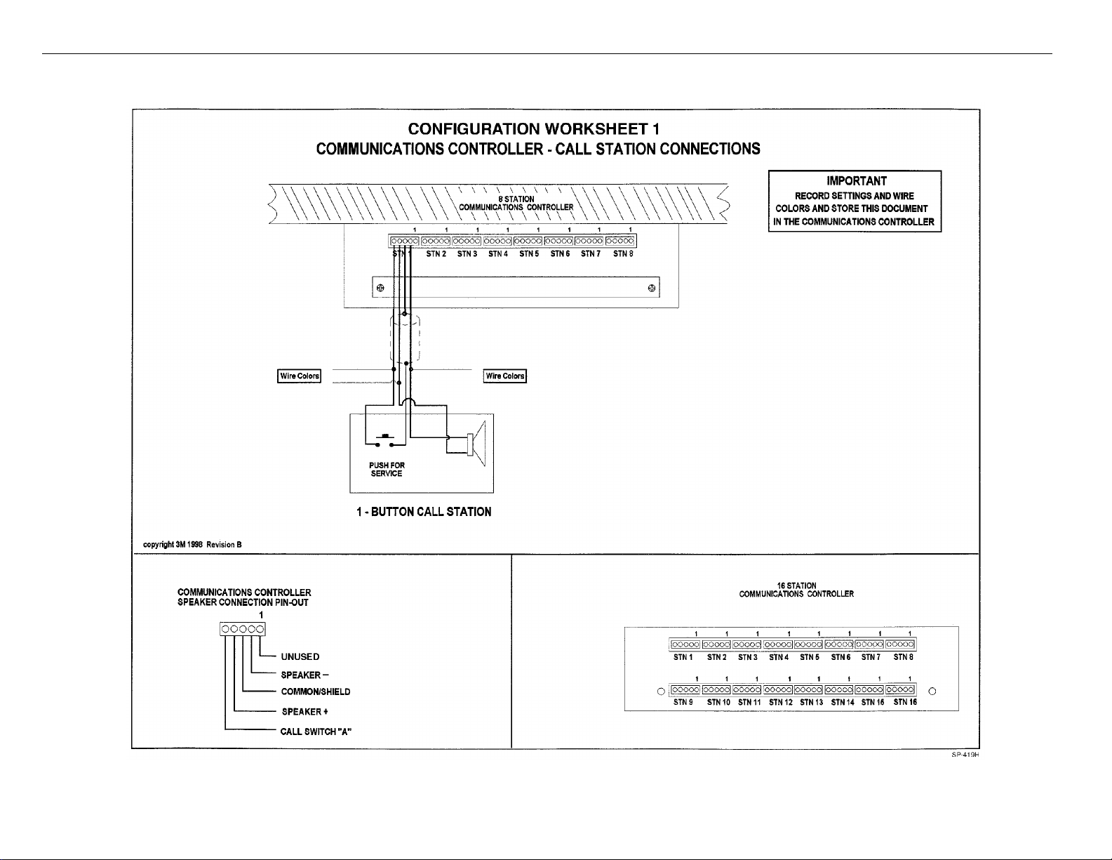
Configuration Worksheets
Use Configuration Worksheets 1 through 3 (located at the end of this document) to plan and record your system
configuration. You can record the system wire locations, wire color scheme, and program settings on the
worksheets. Store the worksheets in the inside cover of the Communications Controller using the service envelope
provided.
Wiring Call Stations
Call Station wiring consists of the following for a one-button, four-wire system:
• 2 Speaker wires.
• Speaker shield wire (used as Common for buttons).
• Button A.
Configuration Worksheet 1 shows how to connect the Call Stations to the proper Communications Controller ports.
Station Selectors
Wiring Station Selectors involves connecting a minimum of 7 wires: 3 audio wires and 4 power and
communications wires.
Important
The D-2400 System is powered by one power supply that provides power for the
Communications Controller and a maximum of three Station Selectors. An individual power
supply must be plugged into the rear of each Station Selector that exceeds the three Station
Selector limit.
Refer to Configuration Worksheets 2 and 3 to determine the specific wires and connections to be made.
6
Page 11

3M Model D-2400
Programming the System
Programming the System
Program the system to conform to your planned configuration and desired operation.
Hardware (Jumpers)
Select Call Station(s) to receive ALL CALL and music/messaging during STANDBY mode. (A closed jumper
turns ALL CALL and music/messaging OFF. An open circuit jumper turns ALL CALL and music/messaging ON.)
1. Use the appropriate jumper to select ALL CALL and music/messaging for each call station.
2. Jumpers JP1 through JP8 (in order) on the Main Board apply to Call Stations 1 through 8; jumpers JP9 through
JP16 (in order) on the Expansion Board apply to Call Stations 9 through 16.
The locations of the jumpers are shown in Figure 6.
Figure 4. Communications Controller Jumpers
7
Page 12

Programming the System
!
{01}
{01}
Programming the Selector
3M Model D-2400
Programming State
1
4
7
2
5 6
8 9
MENU
0
Figure 5. D-2400 Keypad
To program the D-2400, it is necessary to put the system in the
programming state. From this state, the entire system is configured
and all memorized parameters are adjusted.
To enter the programming state, simultaneously:
Press and hold the STD BY key.
Enter the numeric code: 97531.
The display shows:
3
The Parameter #, Parameter Name/Value, and Parameter Value
T
fields are as shown below.
01:Selector ID #
A
L
K
SP-389C
Parameter # Name/Value
↓ ↓↓
01:Selector ID #
Parameter
↑↑
Parameter Value
The _ indicates cursor position. To move the cursor from one field
to another, use the Left Arrow and Right Arrow keys.
To input data at the cursor position, do one of the following:
• Use the Up Arrow and Down Arrow keys to scroll to
desired value.
• Use the 1, 2, 3, 4, 5, 6, 7, 8, 9, 0/Menu keys.
The STD BY key clears a field to a default value (space for text or
the default value).
The HOLD key shifts case for text data.
The ALL CALL key exits from the programming state and enters
the Off Line mode.
Important
All Selectors ship from the factory with a default ID number of 15. It is important to connect
and power up each new selector, ONE SELECTOR AT A TIME, when installing a new
system. Doing this allows you to change the ID number to a lower value (start at 1) and avoid
the erratic behavior caused by multiple selectors sharing the same ID number.
8
Page 13

3M Model D-2400
Programming the System
Keypad Function
Definitions
(Programming State)
2
5 6
8
MENU
0
pad
3
9
1
4
7
Figure 6. D-2400 Key-
T
A
L
K
SP-389C
Key functions are defined below.
Key Function
HOLD (Shift) Shifts between upper and lower case for text data.
UP ARROW Increments data by 1. Fields wrap around.
DOWN ARROW Decrements data by 1. Fields wrap around.
1 Enters the digit 1 for numeric entry.
Enters the following for text entry:
Unshifted A B C 1 (
Shifted a b c 1 )
2 Enters the digit 2 for numeric entry.
Enters the following for text entry:
Unshifted
D E F 2 [
Shifted d e f 2 ]
3 Enters the digit 3 for numeric entry.
Enters the following for text entry:
Unshifted G H I 3 {
Shifted g h i 3 }
4 Enters the digit 4 for numeric entry.
Enters the following for text entry:
Unshifted J K L 4
Shifted j k l 4
5 Enters the digit 5 for numeric entry.
Enters the following for text entry:
Unshifted M N O 5 :
Shifted m n o 5 ;
←
→
9
Page 14

Programming the System
6 Enters the digit 6 for numeric entry.
7 Enters the digit 7 for numeric entry.
8 Enters the digit 8 for numeric entry.
3M Model D-2400
Key Function
Enters the following for text entry:
Unshifted P Q R 6 _
Shifted p q r 6 |
Enters the following for text entry:
Unshifted S T U 7 .
Shifted s t u 7 !
Enters the following for text entry:
Unshifted V W X 8 &
Shifted v w x 8 @
9 Enters the digit 9 for numeric entry.
Enters the following for text entry:
Unshifted Y Z # 9 ’
Shifted y z , 9 “
0/MENU Enters the digit 0 for numeric entry.
Enters the following for text entry:
Unshifted + * = 0 <
Shifted - /
LEFT ARROW Jump left to next data field.
RIGHT ARROW Jump right to next data field.
ALL CALL Exits the programming state and enters Off Line mode.
STD BY Clear the data field to its default value (space for text or
the default value).
TALK Enter key where appropriate.
0 >
∧
10
Page 15

3M Model D-2400
NO COMMUNICATION
{01}
{16}
{08}
{Chime}
{Off}
{15}
Programming the System
Error Message
! E R R O R !
Parameter Selection
01:Selector ID #
02:Max Stations
03:Alert Volume
The system will display one error message: No Communication.
The message occurs when there is no communications between the Selector
and Controller. To correct this:
1. Be sure Controller is powered on.
2. Be sure pins 2 and 3 of J22 on the Controller are connected to pins 2 and
3 of J8 on the Selector. Polarity must be correct.
Memorized parameters are given below. These parameters are stored in the
EEPROM. The 16-character by 2-row LCD displays the parameters.
A number (1 to 15 inclusive). Default = 15. This Number must be unique
relative to all other Selector ID numbers used in the system.
A number (1 to 16 inclusive). Total number of Call Stations in the system.
Default = What the controller senses. Stations are numbered starting with 1
up to this value.
Selector. A number (1 to 15 inclusive). Default = 08.Adjusts the volume of the
alert tone (Chime or Beep). A value of 15 is the loudest setting.
04:Alert Type
05:VOX Enable
06:VOX Sensitive
Beep or Chime. Default = Chime.
On or Off. Default = Off. Enables the VOX (Voice Activated Transmission)
feature
A number (1 to 15 inclusive). Default = 15 (most sensitive).
11
Page 16

Programming the System
S=xx: User Name
S=xy: User Name
‘T A L K’ = Yes
‘T A L K’ = Yes
Se=a.bc Con=x.yz
‘T A L K’ = Yes
3M Model D-2400
07:Priority{Off}
08:Auto Standby
09:Station Name
10:Sync All Data
Are You Sure ?
11:Software Rev.
A value (Off, 1 to 16 inclusive). Priority station #, always moves to top of
queue.
On or Off. Enables the 30 second station connection time out. Default = On.
Assignment of station names 01 through Max Stations where xx indicates
station #. Default = PUMP # xy, xy = station #.
Command to synchronize all Selectors with the data in the Controller and the
Selector that issued the command.
This confirmation message follows the above. Selectors must be On Line to
be synchronized.
Read from Selector & Controller. Selector and Controller software revision
numbers.
Re-Initializing the
Selector
Initialize All ?
To re-initialize the Selector to its original factory settings:
1. Remove Power to the Selector.
2. Press the ALL CALL key.
3. Apply Power to the Selector.
4. Release the ALL CALL key.
5. Confirm the re-initialize procedure by pressing the TALK key. (To abort,
press the STD BY key.)
6. Remember to adjust all of the parameters so that the Selector functions
properly in its given installation.
12
Page 17

3M Model D-2400
Adjusting the System
Adjusting the System
Communications Controller
You must remove the cover from the Communications Controller to perform the following adjustments.
Outbound ALL CALL Volume Level
To set the outbound ALL CALL Volume Level:
1. Ask another attendant to stand near a Call Station that is not in use.
2. Press and hold the ALL CALL button on the Station Selector to make the connection to the Call Stations.
3. Speak to the attendant near the Call Station to determine if the volume is low, satisfactory, or high.
4. If the volume is unsatisfactory, adjust the ALL CALL volume control in the Communications Controller. (See
Figure 8.) Turn clockwise to increase the volume, counter-clockwise to decrease it.
5. Repeat Steps 2 through 4 until the volume is satisfactory.
Outbound Talk Volume Level
To set the outbound talk volume, do the following:
1. Press the Station Selector number key representing the Call Station you have chosen.
2. Speak to the attendant at the Call Station to determine if the volume is low, satisfactory, or high.
3. If the volume is unsatisfactory, adjust TALK A in the Communications Controller (see Figure 7). Turn
clockwise to increase the volume, counter-clockwise to decrease it.
4. Repeat Steps 2 and 3 until the volume is satisfactory.
5. Press STD BY on the Station Selector to cancel the connection to the Call Station.
Figure 7. Communications Controller Volume Controls
13
Page 18

Adjusting the System
!
!
3M Model D-2400
Outbound Music/Messaging Level (Only for Systems That Use Music/Messaging)
To set the outbound Music/Messaging level, do the following:
1. Ask another attendant to stand near a Call Station that is not in use and has Music/Messaging activated.
(See the Communications Controller Hardware Section on Page 7 for details on how to activate
Music/Messaging for a Call Station.)
2. Determine if the Music/Messaging volume is low, satisfactory, or high.
3. If the volume is unsatisfactory, adjust the MUSIC volume control in the Communications Controller. (See
Figure 8.) Turn clockwise to increase the volume, counter-clockwise to decrease it.
4. Repeat Steps 2 and 3 until the volume is satisfactory.
Station Selector(s)
Inbound Audio Volume Level
To set the inbound audio volume level:
1. Ask an attendant to stand at a Call Station and push the incoming call button for your Station Selector.
2. Answer the call by pressing the TALK button.
3. As the attendant talks, adjust the up/down arrows on the Station Selector keypad to reach a desirable level.
VOX (Voice Activated Transmission) Sensitivity Level
Important
The VOX adjustments are necessary only if VOX is enabled for your system.
The VOX sensitivity level determines the maximum distance from the microphone that the speaker can activate
communication.
Important
The suggested average activation distance from the microphone to the attendant is 2 to 6
inches.
14
Page 19

3M Model D-2400
To set the VOX sensitivity level:
1. Follow the directions under the section Programming the Selector to put the Selector in Programming mode.
2. Locate the VOX Enable screen and be sure it is set to ON.
3. Locate the VOX Sensitive screen and press the right-arrow key to edit the value.
4. Use the up/down arrow keys to adjust sensitivity:
• The up arrow key increases the sensitivity (lengthens the distance from the microphone to the attendant).
Fifteen is most sensitive.
• The down arrow key decreases sensitivity. One is least sensitive.
5. Press the ALL CALL key to exit Programming mode.
Adjusting the System
Testing the Functions
Perform the following tests after installing the Convenience Store Intercom System, Model D-2400:
1. Checking TALK/LISTEN switching.
a. Ask an attendant to go to Call Station 1 and press the call button.
b. Establish a connection with the CALL STATION (press TALK on the Station Selector or Remote
Microphone).
c. Talk and listen to the attendant to determine that the TALK and LISTEN modes are functioning
satisfactorily.
d. Repeat Steps a through c for all CALL STATIONS.
2. Checking ALL CALL.
a. Ask an attendant to go to a Call Station.
b. Activate ALL CALL (press and hold ALL CALL on the Station Selector or Remote Microphone).
c. Broadcast an announcement from the Station Selector.
d. Ask the attendant to verify that the message is broadcast from all CALL STATIONS.
15
Page 20

Adjusting the System
3M Model D-2400
This page intentionally left blank.
16
Page 21

3M Model D-2400
Training Users
Training Users
Train users of the Convenience Store Intercom System, Model D-2400, by performing the following steps:
1. Powering the system up (it should remain on).
2. Answering a call.
3. Initiating a call.
4. Adjusting inbound volume.
5. Operation of any applicable equipment.
- Remote Microphone.
- Music/Message unit.
17
Page 22

Training Users
3M Model D-2400
This page intentionally left blank.
18
Page 23
3M Model D-2400
Configuration Worksheets
Configuration Worksheets
19
Page 24

Configuration Worksheets
COMMUNICATIONS CONTROLLER - STATION SELECTOR RS-485 and OTHER CONNECTIONS
3M Model D-2400
CONFIGURATION WORKSHEET 2
COMMUNICATIONS CONTROLLER
D - 2400
Max Station
Priority
Auto Standby (Off, On)
SETTINGS
(1 - 16)
(Off, 1, ..., 16)
TO ADDITIONAL
STATION SELECTORS
RECORD
RECORD
WIRE COLORS
RECORD SETTINGS AND WIRE COLORS.
STORE THIS DOCUMENT IN THE
COMMUNICATIONS CONTROLLER.
TO POWER
RECORD
WIRE COLORS
RECORD RECORD
WIRE COLORS
WIRE COLORSWIRE COLORS
IMPORTANT
20
SP-412C
Page 25

3M Model D-2400
CONFIGURATION WORKSHEET 3
COMMUNICATIONS CONTROLLER-STATION SELECTOR
AUDIO CONNECTIONS
TO
MUSIC/MESSAGE
SOURCE
RECORD
WIRE COLORS
Configuration Worksheets
IMPORTANT:
RECORD WIRE COLORS.
STORE THIS DOCUMENT IN THE
COMMUNICATIONS CONTROLLER.
COMMUNICATIONS CONTROLLER
D - 2400
TO POWER
RECORD
WIRE COLORS
21
RECORD
WIRE COLORS
TO ADDITIONAL
STATION SELECTORS
RECORD
WIRE COLORS
SP-413C
Page 26

3M
Food Services Trade Department
3M Center
St. Paul, MN 55144-1000
Printed on recycled paper.
Printed in U.S.A.
© 3M 2001 January
78-6912-0725-8 Rev C
 Loading...