

Page 1

INSTALLATION AND OPERATING
INSTRUCTIONS
CFSM1254 WATER SOFTENER
Installer: Please leave this manual with owner/operator.
Owner/Operator: Please retain for operation and future
maintenance instructions.
Page 2
SAFETY INFORMATION
WARNING
CAUTION
Read, understand, and follow all safety information contained in these instructions prior to installation and use of the CFSM1254 Water
Softener. Retain these instructions for future reference. Failure to follow installation, operation and maintenance instructions may result
in property damage and will void warranty.
Intended use:
The CFSM1254 Water Softener is intended for use in softening water and has not been evaluated for other uses. The system must be
installed indoors near the point of entry of a water line, and be installed by qualifi ed professional installers according to these installation
instructions.
EXPLANATION OF SIGNAL WORD CONSEQUENCES
W
Indicates a potentially hazardous situation, which, if not avoided, could result in death or serious injury and/or property damage.
Indicates a potentially hazardous situation, which, if not avoided, may result in property damage.
WARNING
To reduce the risk associated with choking:
• Do not allow children under 3 years of age to have access to small parts during the installation of this product.
To reduce the risk associated with ingestion of contaminants:
• Do not use with water that is microbiologically unsafe or of unknown quality without adequate disinfection before or after the system.
To reduce the risk of physical injury:
• Shut off inlet water supply and depressurize system as shown in manual prior to service.
To reduce the risk associated with a hazardous voltage:
• If the electrical system requires use of the cold water system as an electrical safety ground, a jumper must be used to ensure a suffi cient ground connection across
the fi lter installation piping — refer installation to qualifi ed personnel.
• Do not use the system if the power cord is damaged — contact qualifi ed service personnel for repair.
To reduce the risk associated with back strain due to the heavy weight of the various system components:
• Follow safe lifting procedures.
CAUTION
To reduce the risk associated with property damage due to water leakage:
• Read and follow Use instructions before installation and use of this water treatment system.
• Installation and use MUST comply with existing state or local plumbing codes.
• Protect from freezing, relieve pressure and drain system when temperatures are expected to drop below 33°F (0.6°C).
• Do not install on hot water supply lines. The maximum operating water temperature of this fi lter system is 110°F (43.3°C).
• Do not install systems in areas where ambient temperatures may go above 110°F (43.3°C) or below 40°F (4.4°C).
• Do not install if water pressure exceeds 100 psi. If your water pressure exceeds 80 psi (552 kPa), you must install a pressure limiting valve. Contact a plumbing professional if you are uncertain how to check your water pressure.
• Do not install where water hammer conditions may occur. If water hammer conditions exist you must install a water hammer arrester. Contact a plumbing
professional if you are uncertain how to check for this condition.
• Where a backfl ow prevention device is installed on a water system, a device for controlling pressure due to thermal expansion must be installed.
• Do not use a torch or other high temperature sources near fi lter system, cartridges, plastic fi ttings or plastic plumbing.
• On plastic fi ttings, never use pipe sealant or pipe dope. Use PTFE thread tape only, pipe dope properties may deteriorate plastic.
• Take care when using pliers or pipe wrenches to tighten plastic fi ttings, as damage may occur if over tightening occurs.
• Do not install in direct sunlight or outdoors.
• Mount system in such a position as to prevent it from being struck by other items used in the area of installation.
• Ensure all tubing and fi ttings are secure and free of leaks.
• SHUT OFF FUEL OR ELECTRIC POWER SUPPLY TO WATER HEATER after water is shut off.
• Do not install system where water lines could be subjected to vacuum conditions without appropriate measures for vacuum prevention.
• Do not apply heat to any fi tting connected to Bypass or Control Valve as damage may result to internal parts or connecting adapters.
• Install on a fl at/level surface. It is also advisable to sweep the fl oor to eliminate objects that could pierce the brine tank.
To reduce the risk associated with property damage due to plugged water lines:
• Pay particular attention to correct orientation of control valve. Water fl ow should match arrow on control valve. The Inlet and Outlet of other water treatment
equipment products will vary depending on the control valve brand used.
Page 3
IMPORTANT NOTES
• The system should be installed on cold water lines only.
• Failure to follow instructions will void warranty.
SECTION DESCRIPTION
TABLE OF CONTENTS
1 BEFORE INSTALLATION
2 INSTALLATION
3 CONTROL VALVE PROGRAMMING AND REGENERATION
4 MAINTENANCE
5 TROUBLESHOOTING AND SERVICE INSTRUCTIONS
6 SPECIFICATIONS & OPERATING DATA
7 PARTS
LIMITED WARRANTY
SECTION 1: BEFORE INSTALLATION
When properly installed, operated, and maintained, your new softener will provide many years of dependable service. Before starting the installation please
read this manual all the way through for an overview, and then follow the installation in proper sequence. Failure to follow instructions will void warranty.
Inspecting And Handling Your Softener:
Inspect the equipment for shipping damage. If damaged, notify the transportation company and request a damage inspection.
Handle the equipment with care. Damage can result if dropped or if the brine tank is set on sharp, uneven projections on the fl oor. When handling, do not
turn the water softener unit upside down.
Make Sure Your Water Has Been Thoroughly Tested:
An analysis of your water should be made prior to the selection of your water conditioning equipment. Your dealer will generally perform this service for you,
and may send a sample to the factory for analysis and recommendations. Enter your analysis below for your permanent record.
Analysis of Your Water:
Hardness gpg Tannins (Humic Acid) ppm
Iron (Fe) ppm Hydrogen Sulfi de (H2S) ppm
Manganese (Mn) ppm Other ppm
pH ppm
Other ppm
IMPORTANT NOTES
Hydrogen sulfi de (H
S) must be tested for at the well site. For accuracy, the sample must be drawn with the
2
pump RUNNING, and the test be completed within ONE minute after the sample is drawn.
Softeners are designed to reduce hardness but can handle reasonable amounts of soluble iron if consideration
is given to content when selecting model and regeneration settings. To treat sulfur (hydrogen sulfi de), bacterial iron, precipitated iron or very high levels of soluble iron requires special equipment in addition to a water
softener. For best results, a Chem-Free Iron Reduction System is recommended for use on waters containing
more than 2 ppm of iron.
1-1
Page 4
Check Your Pumping Rate and Water Pressure:
Two water system conditions must be checked carefully to avoid unsatisfactory operation or equipment damage:
1) MINIMUM water pressure required at the water softener inlet is 20 psi (1.4 bar). IF WATER PRESSURE IS OVER 80 psi (552 kPa), A PRESSURE REDUCING VALVE MUST BE INSTALLED IN THE WATER SUPPLY LINE AHEAD OF THE WATER SOFTENER.
CAUTION
To reduce the risk associated with property damage due to water leakage:
• Do not install if water pressure exceeds 100 psi. If your water pressure exceeds 80 psi (552 kPa), you must install a pressure limiting valve. Contact a plumbing professional if you are uncertain how to check your water pressure.
NOTE: If you have a municipal or a community water supply and daytime water pressure is 85 psi or more, nighttime pressure may exceed 100
psi. Call your local water department or plant operator to obtain pressure readings. If you have a private well, the gauge on the pressure tank will
indicate the high and low system pressure. Record your water pressure data below:
Water Pressure:
Low psi High psi
CAUTION
To reduce the risk associated with property damage due to water leakage:
• Do not install system where water lines could be subjected to vacuum conditions without appropriate measures for vacuum prevention.
The installer should take appropriate measures if there is the possibility a vacuum may occur. This would include the installation of an appropriate
device in the supply line to the system, i.e., a vacuum breaker or backfl ow prevention device. Vacuum damage voids the factory warranty.
2) The pumping rate of your well must be suffi cient for satisfactory operation and BACKWASHING of the water softener. (See SPECIFICATIONS AND
OPERATING DATA, Section 6)
Locate Water Conditioning Equipment Correctly:
Select the location of your water softener with care. Various conditions which contribute to proper location are as follows:
1) Locate as close as possible to water supply source.
2) Locate as close as possible to a drain.
3) Locate in correct relationship to other water conditioning equipment (Figure 1).
4) Locate the softener in the supply line BEFORE the water heater. Temperatures above 100°F (38°C) will damage the softener and void the factory
warranty.
5) DO NOT install the softener in a location where freezing temperatures occur. Freezing may cause permanent damage and will also void the factory
warranty.
6) Allow suffi cient space around the installation for easy servicing.
7) Provide a non-switched 110V, 60Hz (220V, 50Hz for specifi ed systems) power source for the control valve.
WARNING
To reduce the risk associated with ingestion of contaminants:
• Do not use with water that is microbiologically unsafe or of unknown quality without adequate disinfection before or after the system.
CAUTION
To reduce the risk associated with property damage due to water leakage:
• Protect from freezing, relieve pressure and drain system when temperatures are expected to drop below 33°F (0.6°C).
• Do not install on hot water supply lines. The maximum operating water temperature of this fi lter system is 110°F (43.3°C).
• Do not install systems in areas where ambient temperatures may go above 110°F (43.3°C) or below 40°F (4.4°C).
1-2
Page 5
Facts to Remember While Planning Your Installation:
1) All installation procedures MUST conform to local and state plumbing codes.
2) Remember that the water softener INLET is attached to the pipe that supplies water (i.e. runs to the pump) and the OUTLET is the line that runs
toward the water heater.
CAUTION
To reduce the risk associated with property damage due to plugged water lines:
• Pay particular attention to correct orientation of control valve. Water fl ow should match arrow on control valve. The Inlet and Outlet of other water treatment
equipment products will vary depending on the control valve brand used.
3) Before commencing the installation it is advisable to study the existing piping system and to determine the size, number and type of fi ttings required.
WARNING
To reduce the risk associated with a hazardous voltage:
• If the electrical system requires use of the cold water system as an electrical safety ground, a jumper must be used to ensure a suffi cient ground connection across
the fi lter installation piping — refer installation to qualifi ed personnel.
4) It is also advisable to sweep the fl oor to eliminate objects that could pierce the brine tank.
IMPORTANT NOTE
Sodium Information: Water softeners utilizing sodium chloride for regeneration add sodium to the water softened water. Persons who are on sodium restricted diets should consider the added sodium as part of their overall sodium intake. As a reference as to how much sodium is added to softened water
consider the following. For each grain per gallon of water hardness that is exchanged from the water supply, 7.5 milligrams per liter of sodium will be added
to the softened water. e.g. 10 grains per gallon (gpg) exchanged will add 75 milligrams of sodium to the softened water.
1-3
Page 6
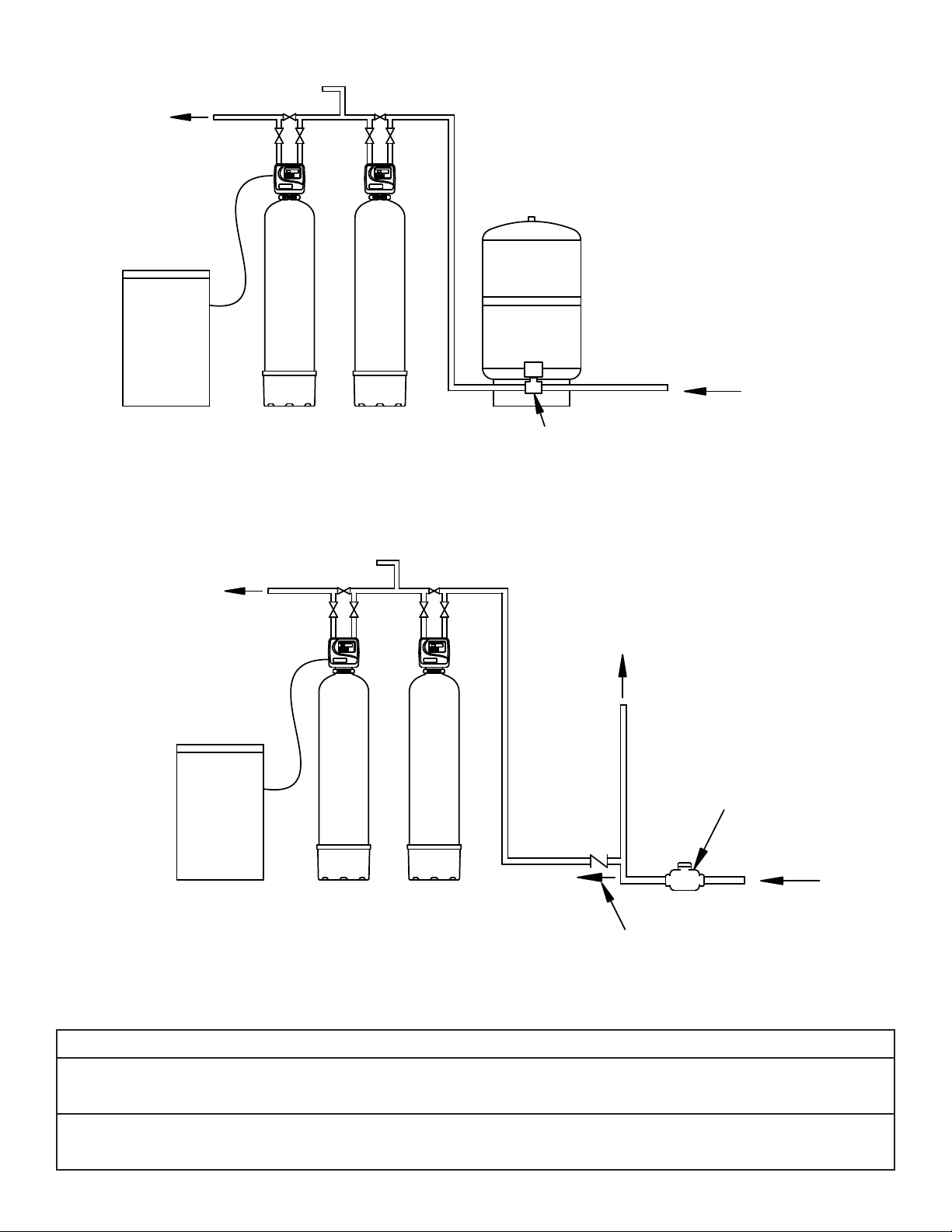
FILTERED
SOFT WATER
BRINE
MAKER
FILTERED WATER
SOFTENER
SECTION 2: INSTALLATION
PRESSURE
TANK
FILTER
PRESSURE
SWITCH.
STANDARD WELL INSTALLATION
RAW
WELL
WATER
FILTERED
SOFT WATER
BRINE
MAKER
FILTERED WATER
WATER FOR
LAWN SPRINKLERS
HIGH DEMAND
SOFTENER
FILTER
PUBLIC WATER SUPPLY INSTALLATION
Figure 1. Typical Installation
OR OTHER
METER
RAW
WATER
CHECK VALVE
CAUTION
To reduce the risk associated with property damage due to water leakage:
• Read and follow Use instructions before installation and use of this water treatment system.
• Installation and use MUST comply with existing state or local plumbing codes.
To reduce the risk associated with property damage due to plugged water lines:
• Pay particular attention to correct orientation of control valve. Water fl ow should match arrow on control valve. The Inlet and Outlet of other water treatment
equipment products will vary depending on the control valve brand used.
2-1
Page 7
SECTION 2: INSTALLATION
Step 1) Remove the unit from the shipping box and remove all packaging. Ensure no freight damage has occurred since shipment from our manufacturing
facility. Locate the parts package and install the bypass and adapter fi ttings on the control valve to facilitate the connection to the customer’s
water supply.
CAUTION
To reduce the risk associated with property damage due to water leakage:
• On plastic fi ttings, never use pipe sealant or pipe dope. Use PTFE thread tape only, pipe dope properties may deteriorate plastic;
• Take care when using pliers or pipe wrenches to tighten plastic fi ttings, as damage may occur if over tightening occurs.
Step 2) Verify all packaging materials have been removed from the brine tank. On all units, legs rest on bottom of the brine tank.
Step 3) Shut off all water at main supply valve. On a private well system, turn off power to the pump and drain pressure tank. Make certain pressure is relieved
from complete system by opening nearest faucet to drain system.
CAUTION
To reduce the risk associated with property damage due to water leakage:
• SHUT OFF FUEL OR ELECTRIC POWER SUPPLY TO WATER HEATER after water is shut off.
Step 4) Cut main supply line as required to fi t plumbing to INLET and OUTLET of unit.
Step 5) Attach plumbing. DO NOT apply heat to any fi tting connected to BYPASS or CONTROL VALVE as damage may result to internal parts or connecting
adapters. MAKE CERTAIN WATER FLOW ENTERS THROUGH INLET AND DISCHARGES THROUGH OUTLET.
WARNING
To reduce the risk associated with a hazardous voltage:
• If the home electrical system requires use of the cold water system as an electrical safety ground, a jumper must be used to ensure a suffi cient
ground connection across the fi lter installation piping — refer installation to qualifi ed personnel.
Step 6) The controls allow for either a 3/4” NPT connection or 5/8” poly tubing for use as a drain line connection.
CAUTION
To reduce the risk associated with property damage due to water leakage:
• On plastic fi ttings, never use pipe sealant or pipe dope. Use PTFE thread tape only, pipe dope properties may deteriorate plastic;
• Take care when using pliers or pipe wrenches to tighten plastic fi ttings, as damage may occur if over tightening occurs.
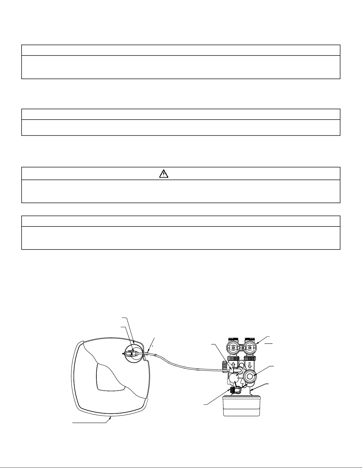
BRINE WELL
SAFETY BRINE
VALVE ASSEMBLY
OVERFLOW
FITTING
BRINE LINE
ELBOW
INOUT
OFF
OFF
OFF
OFF
BYPASS VALVE
INJECTOR COVER
BRINE TANK
DRAIN LINE FLOW
CONTROL ASSEMBLY
Figure 2. SOFTENER AND BRINE TANK ASSEMBLY, TOP VIEW
2-2
CONTROL VALVE BODY
Page 8
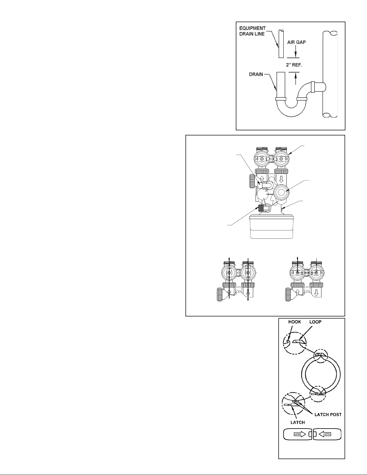
Step 7) Attach DRAIN LINE to DRAIN LINE FITTING. To prevent back pressure from reducing fl ow
rate below minimum required for backwash, DRAIN LINE MUST be sized according to run
length and relative height. Be careful not to bend fl exible drain tubing sharply enough to
cause “kinking” (if kinking occurs DRAIN LINE MUST BE REPLACED). Typical examples of
proper DRAIN LINE diameters are:
1) 1/2” ID up to 15 ft. when discharge is lower than INLET.
2) 5/8” ID up to 15 ft. when discharge is slightly higher than the INLET.
3) 3/4” ID when drain is 25 ft. away and/or drain is installed overhead.
Some areas prohibit the use of fl exible drain lines. Check with local code offi cials prior to
installation.
Step 8) Position DRAIN LINE over drain and secure fi rmly. To prevent backsiphoning of sewer
water, provide an air-gap of at least 2” or 2 pipe diameters between end of drain hose and
drain (Figure 3). DO NOT raise DRAIN LINE more than 10 ft. above fl oor.
Step 9) Connect one end of the 3/8” black Polyethylene tubing to the brine
fi tting located on the left side of the CONTROL VALVE. Connect the
other end to the SAFETY BRINE VALVE ELBOW inside of the brine
well in the brine tank. To do so remove the retaining clip from the
brine line fi tting on the control valve. The retaining clip is holding
BRINE LINE
ELBOW
a plastic insert sleeve and needs to be inserted into the polyethylene tubing before installing the tubing into the fi tting elbow and
hand tighten only. CAUTION: Do not use pliers or wrenches to
tighten as damage may occur and will void the manufacturer’s
warranty.
Figure 3
INOUT
OFF
OFF
OFF
OFF
BYPASS VALVE
INJECTOR COVER
Step 10) Install OVERFLOW LINE to brine tank OVERFLOW FITTING (Figure 2).
Discharge of line must be lower than OVERFLOW FITTING. DO NOT
INTERCONNECT OVERFLOW LINE WITH VALVE DRAIN LINE.
Step 11) Make certain BYPASS VALVE INLET and OUTLET KNOBS ARE IN
DRAIN LINE FLOW
CONTROL ASSEMBLY
“BYPASS” position. After all plumbing connections have been
completed, open main water shut-off valve or restore power to
well pump. Check for leaks and correct as necessary.
Step 12)Plug CONTROL VALVE POWER CORD into 120v/60Hz, non-switched power
source. Manually stage control to BACKWASH POSITION and then
unplug power cord to prevent the unit from advancing automatically.
NORMAL OPERATION BYPASS OPERATION
Treated Water
Exits
OFF
OFF
Supply Water
Enters
OFF
OFF
Step 13) Partially open INLET knob on bypass valve (Figure 4). This will
allow the unit to fi ll slowly from the bottom up, reducing air entrapment. Allow unit to fi ll slowly, failure to do so could result in
loss of resin to the drain. Once a steady stream of water, no air,
is fl owing to drain the inlet and outlet knobs on the bypass can be
Figure 4. BYPASS VALVE
fully opened.
Step 14) Plug the power cord back into the power source. Press the REGEN button and wait for the valve to advance to the
next regeneration position. Repeat the process until the valve is in Service Position (Time will be on the display).
Step 15) Refer to Section 3: Regeneration Instructions, on how to set control valve for proper set up and regeneration
settings.
NOTE: Regeneration settings for the control valve are factory preset. The control valve design permits adjustment
of the salt setting. This adjustment may be necessary when unusual operating conditions exist, such as high
concentrations of iron, manganese or hardness and/or high fl ow rates or daily water consumption.
Supply (Untreated)
Water Exits
CONTROL VALVE BODY
Supply Water
Enters
OFF
OFF
OFF
OFF
SPECIAL SERVICE INSTRUCTIONS:
Under normal circumstances removal of valve should not be required. However, if it must be removed, it
can be done by disassembling the quick release clamp, and latch. Pressure should be relieved before attempting any
disassembly. Upon reassembly, all o-rings should be lubricated with silicone grease. Reassemble clamp as shown in
Figure 5. MAKE SURE ARROWS ON LATCH SIDE OF CLAMP ARE ALIGNED.
Figure 5.
2-3
Clamp Assembly
Page 9
SECTION 3: CONTROL VALVE PROGRAMMING AND REGENERATION
Grains Capacity/lb NaCl 6,000 to 3,000
2
Lbs NaCl/cu ft resin
Cycle Time
in Minutes
Backwash Normal 8
Regenerate 60
Backwash Normal 10
Rinse 8
Total
Less than 7.5
3
86
Step 1
Step 2
Step 3
WS1 & WS 1.25 Downfl ow
Regenerant Refi ll After Rinse
1st Cycle Backwash
2nd Cycle Regenerate
3rd Cycle Backwash
4th Cycle Rinse
5th Cycle Fill Dissolve
6th Cycle Service
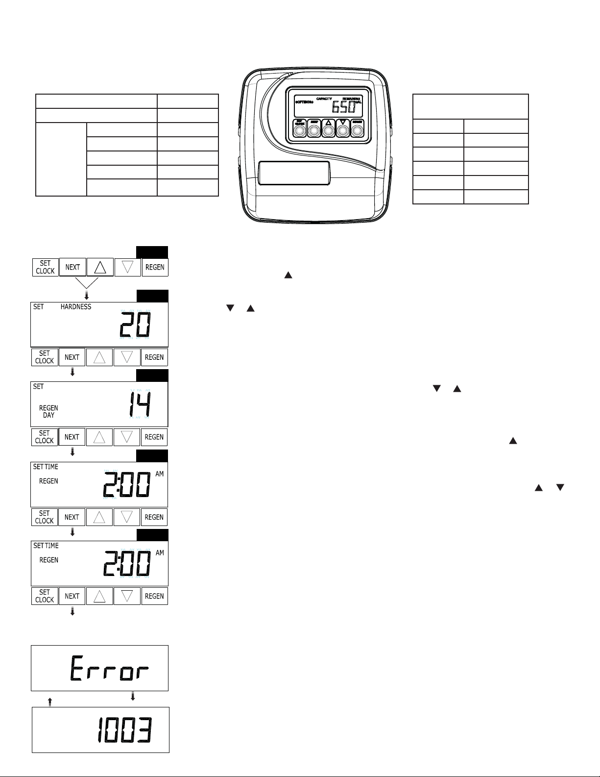
Installer Display Settings
(Step 1) Press NEXT and simultaneously for 3 seconds.
(Step 2) Hardness: Set the amount of hardness in grains of hardness as calcium carbonate per gallon
using the or buttons. The default is 20 with value ranging from 1 to 150 in 1 grain increments.
Note: The grains per gallon can be increased if soluble iron needs to be reduced. Press NEXT to go
to Step 3. Press REGEN to exit Installer Display Settings.
(Step 3) Day Override: Day Override sets the number of days between regenerations and sets the
maximum number of days between regenerations. If value is set as a number (allowable range from
1 to 28) a regeneration initiation will be called for on that day even if suffi cient number of gallons
were not used to call for a regeneration. Set Day Override using or buttons.
• number of days between regeneration (1 to 28); or “OFF”.
Press NEXT to go to Step 4. Press REGEN to return to previous step.
RETURN TO
NORMAL MODE
Step 4
Step 5
(Step 4) Next Regeneration Time (hour): Set the hour of day for regeneration using or buttons.
AM/PM toggles after 12. The default time is 2:00 a.m. Press NEXT to go to Step 5. Press REGEN to
return to previous step.
(Step 5) Next Regeneration Time (minutes): Set the minutes of day for regeneration using or
buttons. Press NEXT to exit Installer Display Settings. Press REGEN to return to previous step.
To initiate a manual regeneration immediately, press and hold the “REGEN” button for three seconds.
The system will begin to regeneration immediately. The control valve may be stepped through the
various regeneration cycles by pressing the “REGEN” button.
Power Lost
If power goes out for less than two hours, the system will automatically reset itself. If an extended
power outage occurs, the time of day will fl ash on and off which indicated the time of day should be
reset. The system will remember the rest.
Error Message
If the word “error” and a number are alternately fl ashing on the display contact the “Technical
Support Services Department” at CUNO Incorporated, phone number 1-866-693-2543 for help. This
indicates that the valve was not able to function properly.
3-1
Page 10

Step 1
Step 2
Diagnostics
(Step 1) Press or simultaneously for 3 seconds. If screen in step does not appear in 5 seconds the
lock on the valve is activated. To unlock press, , NEXT, , and SET CLOCK in sequence, then press
NEXT and simultaneously for 3 seconds.
(Step 2) Days, since last regeneration: This display shows the days since the last regeneration occurred.
Press the NEXT button. Press REGEN to exit Diagnostics.
Step 3
Step 4
Step 5
Step 6
Step 7
(Step 3) Gallons, since last regeneration: This display shows the number of gallons that have been
treated since the last regeneration. This display will equal zero if a water meter is not installed. Press
the NEXT button. Press REGEN to return to previous step.
(Step 4) Gallons, reserve capacity used for last 7 days: This display shows 0 day (for today) and fl ashes
the reserve capacity. Pressing the
button show day 1 (which would be yesterday) and fl ashes the
reserve capacity used. Pressing the button again will show day
2 (the day before yesterday) and reserve capacity. Keep press-
ing the button to show the gallons for days 3, 4, 5 and 6. The
button can be pressed to move backwards in the day series.
Press the NEXT button at any time. Press REGEN to return to
previous step.
(Step 5) Gallons, 63 day usage history: This display shows day 1 (for yesterday) and fl ashes
the number of gallons treated yesterday. Pressing the
button will show day 2 (which would be the day before yesterday) and fl ashes the number of gallons treated on that day.
Continue to press the button to show the
maximum number of gallons treated for the last 63 days. This display will show dashes if a water meter
is not installed. Press the NEXT button at any time. Press REGEN to return to previous step.
(Step 6) Flow rate, current: Turn the water on at one or more taps in the building. The fl ow rate in gallons
per minute will be displayed. If fl ow stops the value will fall to zero in a few seconds. This display will
equal zero if a water meter is not installed. Press the NEXT button. Press REGEN to return to previous
step.
RETURN TO
NORMAL MODE
Step 8
Step 9
Step 10
(Step 7) Flow rate, maximum last seven days: The maximum fl ow rate in gallons per minute that occurred
in the last seven days will be displayed. This display will equal zero if a water meter is not installed.
Press the NEXT button. Press REGEN to return to previous step.
(Step 8) Gallons, total used since last reset: The total number of gallons used since last reset will be
displayed. This display will equal zero if a water meter is not installed. Press the NEXT button. Press
REGEN to return to previous step.
(Step 9) Days, total number since last reset: The total number of days the control valve has been in service since last reset will be displayed. Press the NEXT button. Press REGEN to return to previous step.
(Step 10) Regenerations, total number since last reset: The total number of regenerations that have
occurred since last reset will be displayed. Press the NEXT button to exit Diagnostics. Press REGEN to
return to previous step. To lock settings press , NEXT, , and SET CLOCK in sequence.
3-2
Page 11

Step 1
Step 1
Step 2
Step 3
Step 4
Valve History
(Step 1) Press or simultaneously for 3 seconds and release. Then press and simultaneously
and release. If screen, to the left, does not appear is 5 seconds the lock on the valve is activated. To
unlock press , NEXT, and SET CLOCK in sequence, then press and . Then press and
simultaneously and release.
(Step 2) Software Version: This display shows the software version of the valve. Press the NEXT but-
ton to go to the next step or press REGEN to exit Valve History.
(Step 3) Flow rate, maximum since startup: This display shows the maximum fl ow rate in gallons per
minute that has occurred since startup. This display will equal zero if a water meter is not functioning. Press the NEXT button to go to the next step. Press REGEN to return to previous step.
(Step 4) Gallons, total used since start-up: This display shows the total gallons. This display shows
the total days since start-up. Press the NEXT button to go to the next step. Press REGEN to return to
previous step.
(Step 5) Days, total since start-up: This display shows the total days since start-up. Press the NEXT
button to go to the next step. Press REGEN to return to previous step.
(Step 6) Regenerations, total number since start-up: This display shows the total number of regenerations that have occurred since start-up. Press the NEXT button to go to the next step. Press
REGEN to return previous step.
Step 5
Step 6
Step 7
(Step 7) Error, number of occurrences since start-up: This display shows E and the total number of
errors that have occurred since start-up. Press the NEXT button to exit Valve History. Press REGEN to
return to previous step. To lock settings press
, NEXT, and SET CLOCK in sequence.
RETURN T
NORMAL MOD
3-3
Page 12

User Display Settings
General Operation
OR
When the system is operating, one of two displays will be
shown. Pressing NEXT will alternate between the displays.
One of the displays is always the current time of day. The second display is one of the following: days remaining or gallons
remaining. Days remaining is the number of days left before
the system goes through a regeneration cycle. Capacity remaining is the number of gallons that will be treated before the
system goes through a regeneration cycle. The user can scroll
between the displays as desired.
REGEN TODAY will be
displayed if a regeneration
is expected “Tonight.”
If the system has called for a regeneration that will occur at the preset time of regeneration, the words “REGEN TODAY” will appear on the
display.
When water is being treated (i.e. water is fl owing through the system) the word “SOFTENING” fl ashes on the display if a water meter is installed.
Regeneration Mode
Typically a system is set to regenerate at a time of low water usage. An example of a time with low
water usage is when members of a household are asleep. If there is a demand for water when the
system is regenerating, untreated water will be used.
When the system begins to regenerate, the display will change to include information about the step of the regeneration process and the time
remaining for that step to be completed. The system runs through the steps automatically and will reset itself to help provide treated water
when the regeneration has been completed.
Manual Regeneration
Sometimes there is a need to regenerate the system sooner than
when the system calls for it, usually referred to as manual regen-
REGEN TODAY will
Flash if a regeneration
is expected “Tonight.”
eration. There may be a period of heavy water usage because of
guests or a heavy laundry day.
To initiate a manual regeneration at the present delayed regeneration time, press and release “REGEN”. The words “REGEN TODAY” will fl ash
on the display to indicate that the system will regenerate at the preset delayed regeneration time.
NOTE: If you pressed the “REGEN” button in error, pressing the button again will cancel the request.
To initiate a manual regeneration immediately, press and hold the “REGEN” button for 3 seconds. The system will begin to regenerate immediately. The request cannot be cancelled.
NOTE: For softeners, if brine tank does not contain salt, fi ll with salt and wait at least two hours before regenerating.
Set Time of Day
The user can also set the time of day. Time should only need to be set after extended
power outages or when daylight saving time begins or ends. If an extended power out-
ages or when daylight saving time begins or ends. If an extended power outage occurs,
the time of day will fl ash on and off which indicates the time of day should be reset.
Step 1 - Press SET CLOCK.
Step 2 - Current Time (hour): Set the hour of the day using or button. AM/PM
toggles after 12. Press NEXT to go to Step 3.
Step 3 - Current Time (minutes): Set the minutes of the day using or buttons.
Press NEXT to exit Set Clock. Press “REGEN” to return to previous step.
3-4
Page 13

SECTION 4: MAINTENANCE
Replenishment of Salt Supply:
The salt storage capacity of the brine tank is approximately 135 lbs. (61 kg). During each regeneration a specifi c amount of salt is consumed, thus requiring its
periodic replenishment (the frequency and salt dosage level is dependent on the regeneration schedule). Always replenish salt before the supply is exhausted
for a continuous supply of softened water.
Type of Salt to Use:
Any type of water softener salt may be used. There are advantages and disadvantages to every type of salt. Please ask your local dealer for his advice. Your
unit is designed to compensate for the disadvantages. However the use of block salt is not encouraged due to its possible problems in making enough brine
for regeneration purposes.
Brine Tank Clean-Out:
To prevent service problems the brine tank should be emptied and fl ushed out with a garden hose when dirt and other insolubles accumulate.
Steps to follow:
(1) Disconnect brine line at either end.
(2) Turn brine tank upside down and discard old salt.
(3) Rinse out with a garden hose.
(4) Reconnect brine line.
(5) Before loading salt, using a pail or garden hose, add enough water to the brine tank to cover the salt grid lower shelf on 15” x 15” x 34” brine tank at least
one (1) inch in depth. Then add initial salt to brine tank and add one (1) cup of unscented laundry bleach to the brine well.
(6) Perform approximately once a year if rock salt is used; with other types of salt, approximately once every other year.
Preventing Iron-Fouling of Mineral Bed:
If iron is present in the water supply, the softener mineral bed will eventually become iron-fouled, resulting in reduced softening capacity and rust-stained
fi xtures. Mixing one to two ounces of IRON-X Mineral Cleaner with every 80 lbs. of salt added to brine tank will help minimize these problems from occurring.
IRON-X is available from your dealer.
Periodically Check Time of Day Setting:
Power outages will cause “TIME OF DAY” setting to become incorrect. To correct, refer to Section 4.
Malfunction of Unit:
Your water softener, under normal conditions, should provide years of virtually trouble-free service; however, since it is a mechanical device, it can malfunction.
(Refer to Section 5, SERVICE INSTRUCTIONS, if necessary).
Change of Operating Conditions:
Should your family size, your water usage habits, or your water quality change, the regeneration program settings may have to be adjusted. Consult your
dealer if any of the above occur.
Special Service Instructions:
Under normal circumstances removal of valve should not be required. However, if it must be removed, it can be done by disassembling the quick release clamp, and
latch. Pressure should be relieved before attempting any disassembly. Upon reassembly, all o-rings should be lubricated with silicone grease. Reassemble clamp
as shown in Figure 5. MAKE SURE ARROWS ON LATCH SIDE OF CLAMP ARE ALIGNED.
4-1
Figure 6. CLAMP ASSEMBLY
Page 14

SECTION 5: CONTROL VALVE TROUBLESHOOTING GUIDE
Problem Possible Cause Solution
1. Timer does not display time of day
2. Timer does not display correct time
of day
3. No softening/fi ltering display when
water is fl owing
4. Control Valve regenerates at wrong
time of day
5. ERROR followed by code number
Error Code 1001 - Unable to recognize start of
regeneration
Error Code 1002 - Unexpected stall
Error Code 1003 - Motor ran too long, timed out
trying to reach next cycle position
Error Code 1004 - Motor ran too long, timed out
trying to reach home position
If other Error Codes display, contact the factory
6. Control valve stalled in regeneration
7. Control valve does not regenerate
automatically when “REGEN” button
is depressed and held
8. Control valve does not regenerate
automatically but does when “REGEN”
button is depressed
9. Time of day fl ashes on and off
A. AC Adapter unplugged A. Connect power
B. No electric power at outlet B. Repair outlet or use working outlet
C. Problem with AC Adapter C. Replace AC Adapter
D. Problem with PC Board D. Replace PC Board
A. Switched outlet A. Use uninterrupted outlet
B. Power outage B. Reset time of day
C. Problem with PC board C. Replace PC board
A. Bypass valve in bypass position A. Put bypass valve in service position
B. Meter connection disconnected B. Connect meter to PC board
C. Restricted/stalled meter turbine C. Remove meter and check for rotation or foreign material
D. Problem with meter D. Replace meter
E. Problem with PC board E. Replace PC board
A. Power outages A. Reset control valve to correct time of day
B. Time of day not set correctly B. Reset to correct time of day
C. Time of regeneration incorrect C. Reset regeneration time
A. Control valve has just been serviced or unplug power
source jack (black wire) and plug back in to reset control
valve.
B. Foreign matter is lodged in control valve B. Check piston and spacer stack assembly
C. High drive forces on piston C. Replace piston(s) and spacer stack assembly
D. Control valve piston not in home position seconds D. Press NEXT and REGEN for 3 seconds or unplug power source jack
E. Motor not inserted fully to engage pinion, motor wires
broken or disconnected, motor failure
F. Drive gear label dirty or damaged, missing or broken
gear
G. Drive bracket incorrectly aligned to back plate G. Reseat drive bracket properly
H. PC board is damaged or problematic H. Replace PC board
I. PC board incorrectly aligned to drive bracket I. Ensure PC board is correctly snapped on to drive bracket
A. Motor not operating A. Replace motor
B. No electric power at outlet B. Repair outlet or use working outlet
C. Problem with AC Adapter C. Replace AC Adapter
D. Problem with PC board D. Replace PC board
E. Broken drive gear or drive cap assembly E. Replace drive gear or drive cap assembly
F. Broken piston retainer F. Replace drive cap assembly
G. Broken main or regenerant piston G. Replace main or regenerant piston
A. AC Adapter unplugged A. Connect AC Adapter
B. No electric power at outlet B. Repair outlet or use working outlet
C. Broken drive gear or drive cap assembly C. Replace drive gear or drive cap assembly
D. Problem with PC board D. Replace PC board
A. Bypass valve in bypass position A. Put bypass valve in normal operating position
B. Meter connection disconnected B. Connect meter to PC board
C. Restricted/stalled meter turbine C. Remove meter and check for rotation or foreign matter
D. Problem with meter D. Replace meter
E. Problem with PC board E. Replace PC board
F. Set-up error F. Check control valve set-up procedure
A. Power has been out more than two hours, the AC
Adapter was unplugged and then plugged back into the
wall outlet, the AC Adapter plug was unplugged and then
plugged back into the board or the NEXT and REGEN buttons were pressed to reset the valve
A. Press NEXT and REGEN for 3 seconds
(black wire) and plug back in to reset control valve
E. Check motor and wiring. Replace motor if necessary
F. Replace or clean drive gear
A. Reset the time of day
5-1
Page 15

SECTION 5: CONTROL VALVE SERVICE INSTRUCTIONS
Drive Assembly:
Remove the valve cover to access the drive assembly.
IMPORTANT NOTE: Disconnect the power source plug (black wire) from the PC board prior to disconnecting the motor or water meter plugs from the PC board. The
power source plug connects to the four-pin jack. The motor plug connects to the two-pin jack on the left-hand side of the PC board. The water meter plug (grey
wire) connects to the three-pin jack on the far right-hand side of the PC board.
The PC board can be removed separately from the drive bracket but it is not recommended. Do not attempt to remove the display panel from the PC board. Handle
the board by the edges. To remove the PC board from the drive bracket, unplug the power, water meter and motor plugs from the PC board. Lift the middle latch
along the top of the drive bracket while pulling outward on the top of the PC board. The drive bracket has two plastic pins that fi t into the holes on the lower edges
of the PC board. Once the PC board is tilted about 45° from the drive bracket it can be lifted off of these pins. To reinstall the PC board, position the lower edge of
the PC board so that the holes in the PC board line up with the plastic pins. Push the top of the PC board towards the valve until it snaps under the middle latch,
weave the power and water meter wires into the holders and reconnect the motor, water meter and power plugs.
The drive bracket must be removed to access the drive cap assembly and pistons or the drive cap gear cover. It is not necessary to remove the PC board from the
drive bracket to remove the drive bracket. To remove the drive bracket, start by removing the plugs for the power source and the water meter. Unweave the wires
from the side holders. Two tabs on the top of the drive back plate hold the drive bracket in place. Simultaneously lift the two tabs and gently ease the top of the
drive bracket forward. The lower edge of the drive bracket has two notches that rest on the back plate. Lift up and outward on the drive bracket to disengage the
notches.
To reassemble, seat the bottom of the drive bracket so the notches are engaged at the bottom of the drive back plate. Push the top of the drive bracket toward the
two latches. The drive bracket may have to be lifted slightly to let the threaded piston rod pass through the hole in the drive bracket. Maintain a slight engaging
force on top of the drive bracket while defl ecting the bracket slightly to the left by pressing on the side of the upper right corner. This helps the drive gears mesh
with the drive cap assembly. The drive bracket is properly seated when it snaps under the latches on the drive back plate. If resistance is felt before latching, then
notches are not fully engaged, the piston rod is not in the hole, the wires are jammed between the drive bracket and drive back plate, or the gear is not engaging
the drive cap assembly. To inspect the drive gears, the drive gear cover needs to be removed. Before trying to remove the gear cover, the drive bracket must be
removed from the drive back plate. (Refer to the proceeding instructions regarding removing the drive bracket from the drive back plate. The drive gear cover can
be removed from the drive bracket without removing the motor or the PC board.) The drive gear cover is held in place on the drive bracket by three clips. The largest
of the three clips is always orientated to the bottom of the drive bracket. With the PC board facing up, push in and down on the large clip on the drive gear cover.
Handle the cover and the gears carefully so that the gears do not fall off of the pegs in the cover.
Replace broken or damaged drive gears. Do not lubricate any of the gears. Avoid getting any foreign matter on the refl ective coating because dirt or oils may
interfere with pulse counting.
The drive gear cover only fi ts on one way, with the large clip orientated towards the bottom. If all three clips are outside of the gear shroud on the drive bracket
and the drive gear cover slips easily into place.
The drive bracket does not need to be removed from the drive plate if the motor needs to be removed. To remove the motor, disconnect the power and motor plugs
from the jacks on the PC board. Move the spring clip loop to the right and hold. Rotate the motor at least a 1/4 turn in either direction so the wires are vertical
(up & down) before gently pulling on the wire connectors to remove the motor. Pulling directly on the wires without rotating the motor may break the wires off the
motor.
Replace the motor if necessary. Do not lubricate the motor or the gears. To reinstall the motor, move the spring clip loop to the right and hold. Gently turn the motor
while inserting so that the gear on the motor meshes with the gears under the drive gear cover. Release the spring clip loop and continue to rotate the motor until
the wires are horizontal and the motor housing engages the small plastic bulge inside the drive bracket motor retainer. Reconnect the motor plug to the two-pronged
jack on the lower left hand side of the PC board. If the motor will not easily engage with the drive gears when reinstalling, lift and slightly rotate the motor before
reinserting. Reconnect the power.
Replace the valve cover. After completing any valve maintenance, press and hold NEXT and REGEN buttons for 3 seconds or unplug power source jack (black wire)
and plug back in. This resets the electronics and establishes the service piston position. The display should fl ash all wording, then fl ash the software version (e.g.
181) and then reset the valve to the service position.
Drive Cap Assembly, Main Piston and Regenerant Piston:
The drive assembly must be removed to access the drive cap assembly. The drive cap assembly must be removed access the piston(s). The drive cap assembly
is threaded into the control valve body and seals with an o-ring. To remove the drive cap assembly use the special plastic wrench or insert a ¼” to ½” fl at blade
screwdriver into one of the slots around the top 2” of the drive cap assembly so it engages the notches molded into the drive back plate around 2” or the piston
cavity. See Figure 7. The notches are visible through the holes. Lever the screwdriver so the drive cap assembly turns to the left. Once loosened, unscrew the drive
cap assembly by hand and pull straight out. The drive cap assembly contains the drive cap, the main drive gear, drive cap spline, piston rod and various other parts
that should not be dissembled in the fi eld. The only replaceable part on the drive cap assembly is the o-ring. Attached to the drive cap assembly is the main piston
and a regenerant piston.
The regenerant piston (the small diameter one behind the main piston) is removed form the main piston by pressing sideways and unsnapping if from its latch.
Chemically clean in dilute sodium or vinegar, or replace the regenerant piston if needed. To remove the main piston fully extend the piston rod and then unsnap the
main piston from its latch by pressing on the side with the number. Chemically clean in dilute sodium bisulfi te or vinegar, or replace the main piston.
5-2
Page 16

Reattach the main piston to the drive cap assembly. Reattach the regenerant piston (if needed)
to the main piston. Do not lubricate the piston rod, main piston or regenerant piston. Lubricant
will adversely affect the clear lip seals. Reinsert the drive cap assembly and piston into the
spacer stack assembly and hand tighten the drive cap assembly. Continue to tighten the drive
cap assembly using a screwdriver as a ratchet until the black o-ring on the spacer stack assembly is no longer visible through the drain port. Excessive force can break the notches molded
into the dive back plate. Make certain that the main drive gear still turns freely.
The exact position is not important as long as the main drive gear turns freely. Reattach the drive
assembly to the control valve and connect all plugs. After completing any valve maintenance,
press and hold NEXT and REGEN buttons for 3 seconds or unplug power source jack (black wire)
and plug back in. This resets the electronics and establishes the service piston position. The
display should fl ash all wording, then fl ash the software version (e.g. 181) and then reset the
valve to the service position.
Figure 7
Spacer Stack Assembly:
To access the spacer stack assembly remove the drive assembly, drive cap assembly and piston. The spacer stack assembly can be removed easily
without tools by using thumb and forefi nger. Inspect the black o-rings and clear lip seals for wear or damage. Replace the entire stack if necessary.
Do not disassemble.
The spacer stack assembly may be chemically cleaned (dilute sodium bisulfi te or vinegar) or wiped with a soft cloth.
The spacer stack assembly can be pushed in to the control valve body bore by hand. Since the spacer stack assembly can be compressed it is
easier to use a blunt object (5/8” to 1-1/8” in diameter) to push the center of the assembly into the control valve body. The assembly is properly
seated with at least four threads are exposed (approximately 5/8’). Do not force the spacer stack assembly in. The control valve body bore interior
can be lubricated with silicone to allow for easy insertion of the entire stack. Do not use silicone or any other type of lubricant on the clear lip seals
or the piston.
Reattach the drive cap assembly and piston(s) and the drive assembly.
After completing any valve maintenance, press and hold NEXT and REGEN buttons for 3 seconds or unplug power source jack (black wire) and plug
back in. This resets the electronics and establishes the service piston position. The display should fl ash all wording, then fl ash the software version
(e.g. 181) and then reset the valve to the service position.
Injector Cap, Screen, Injector Plug and Injector:
Unscrew the injector cap and lift off. Loosen cap with special plastic wrench or pliers if necessary. Attached to the injector cap is a screen. Remove the screen and
clean if fouled. The plug and/or injector can be pried out with a small screwdriver. The plug can be wiped clean. If the plug leaks replace the entire plug. The injector consists of a throat and a nozzle. Chemically clean the injector with vinegar or sodium bisulfi te. The holes can be blown out with air. Both pieces have a small
diameter holes that control the fl ow rates of water to insure that the proper concentration of regenerant is used. Sharp objects, which can score the plastic, should
not be used to clean the injector. Scoring the injector or increasing the diameter of the hole could change the operating parameters of the injector. Push the plug(s)
and/or injectors fi rmly in place, replace the screen and hand tighten the injector cap.
Refi ll Flow Control Assembly or Refi ll Port Plug:
To clean or replace the refi ll fl ow control, pull out the elbow-locking clip and then pull straight up on the elbow. Replace the elbow locking clip in the
slot so that it is not misplaced. Twist to remove the white fl ow control retainer. The fl ow control can be removed by prying upward through the side
slots of the retainer with a small fl at blade screwdriver.
Clean the fl ow control or the white fl ow control retainer using dilute sodium bisulfi te or vinegar. Do not use a wire brush. If necessary, replace the
fl ow control, o-ring on the fl ow control retainer, or the o-ring on the elbow.
Reseat the fl ow control so the rounded end is visible in the fl ow control. Reseat the white fl ow control retainer by pushing the retainer into the
elbow until the o-ring seats. Remove locking clip, push down on elbow to reseat and insert locking clip. Do not use petroleum jellies, oils, or other
unacceptable on o-rings. A silicone lubricant may be used on the o-ring on the elbow or the white retainer.
Water Meter or Meter Plug:
The water meter assembly is connected to the PC board by a wire. If the entire water meter assembly is to be replaced, remove the control valve cover and disconnect the power source and water meter plugs from the PC Board. Unlatch the drive assembly and lean if forward. Unthread the water meter wire from the side of the
drive assembly and through the drive back plate. To reinstall, rethread the water meter wire through the drive back plate and the side of the drive assembly. Reattach
the drive assembly and the water meter and power plugs. If no water meter wire is visible, then a plug is installed, not a water meter. The water meter wire does
not need to be removed from the PC board if the water meter is only being inspected and cleaned. To remove the water meter assembly, unscrew the meter cap on
5-3
Page 17

the left side of the control valve. Pliers may be used to unscrew the nut if necessary. With the nut removed, a slot at the top of the water meter is visible. Twist a fl at
blade screwdriver in the slot between the control valve body and the meter. When the meter is part way out it is easy to remove the water meter from the housing.
Once the water meter is removed from the control valve body, gently pull forward on the turbine to remove it from the shaft.
Do not use a wire brush to clean the turbine. Wipe with a clean cloth or clean in dilute sodium bisulfi te or vinegar. The turbine can be immersed in the chemical. Do
not immerse electronics. If the turbine is scored or damaged or the bearing on the turbine are worn, replace the turbine.
Do not lubricate the turbine shaft. The turbine shaft bearings are prelubricated. Do not use petroleum jellies, oils, or other unacceptable lubricants on the o-ring. A
silicone lubricant may be used on the black o-ring.
Snap the turbine on the shaft and reinsert the water meter into the side slot. Hand tighten the nut. Do not use a pipe wrench to tighten nut.
Bypass Valve:
The working parts of the bypass valve are the rotor assemblies that are contained under the bypass valve caps. Before working on the rotors, make sure the system
is depressurized. Turn the red arrow shaped handles towards the center of the bypass valve and back several times to ensure rotor is turning freely.
The nuts and caps are designed to be unscrewed or tightened by hand. If necessary a pliers can be used to unscrew the nut or cap. Do not use a pipe wrench to
tighten or loosen nuts or caps. Do not place screwdriver in slots on caps and/or tap with a hammer. To access the rotor, unscrew the cap and lift the cap, rotor and
handle out as one unit. Twisting the unit as you pull it out will help to remove it more easily. There are three o-rings: one under the rotor cap, one on the rotor stem
and the rotor seal. Replace worn o-rings. Clean rotor. Reinstall rotor.
When reinstalling the red arrow handles be sure that:
1. The handle pointers are lined up with the control valve body arrows, and the rotor seal o-ring and the retainer on both rotors face to the right when being
viewed from the front of the control valve; or
2. Arrows point toward each other in the bypass position.
Since the handles can be pulled off, they could be accidentally reinstalled 180° from their correct orientation. To install the red arrow handles correctly, keep the
handles pointed in the same direction as the arrows engraved on the control valve body while tightening the bypass valve caps. After completing and valve maintenance, press and hold NEXT and REGEN buttons for 3 seconds or unplug power source jack (black wire) and plug back in. The resets the electronics and establishes
the service piston position. The display should fl ash all wording, then fl ash the software version (e.g. 181) and then reset the valve to the service position.
5-4
Page 18

SECTION 5: SYSTEM TROUBLESHOOTING GUIDE
Problem Cause Solution
A. Electrical service to unit interrupted A. Assure permanent electrical service (check fuse, plug, pull chain,
B. Timer not working. B. Replace timer assembly.
1. Hard water (unit not using salt; liquid level in
brine tank NOT too high)
2. Hard water (unit using salt; liquid level in
brine tank NOT too high)
3. Liquid level in brine tank TOO high
4. System regenerates at wrong time
of day
5. Water continuously fl ows to drain
6. Water tastes salty
7. White spots on glassware and dark surfaces
8. Low water pressure (low fl ow rate)
9. “Rotten egg” smell (from hot water only) A. Magnesium rod in water heater A. Replace with aluminum rod or remove
10. “Rotten egg” smell (from both hot and cold
water
11 Loss of resin through drain
C. Timer improperly set C. Check programming function
D. Safety brine valve not opening D. Replace safety brine valve
E. Salt “bridged” in brine tank E. Breakup salt
F. Meter not functioning F. Clean or replace as necessary
A. Bypass open A. Close bypass (replace if necessary)
B. Timer improperly set B. Increase frequency of regeneration
C. No salt in brine tank C. Add salt; maintain above water level
D. Excessive water usage D. Increase frequency of regeneration and/or salt setting (See HOW TO
E. Unit installed backwards E. Reinstall unit
F. Unit undersized F. Replace with larger unit
A. Brine valve not closing A. Replace brine valve
B. Salt setting too high B. Reset timer
C. Injector or Injector screen plugged C. Clean injector and screen
D. Drain line frozen, plugged or restricted D. Free drain
E. Salt “mushed” or sand from salt plugging bottom of
brine tank
F. Incorrect brine line fl ow control (BLFC) F. Replace with correct fl ow control (see specifi cations)
A. Timer improperly set A. Reset timer
A. Foreign material in control valve A. Remove piston assembly and inspect bore: remove foreign material
B. Internal control leak B. Replace seals and/or piston assembly
C. Control valve jammed in brine or backwash position C. Replace piston, seals and spacers
A. Salt setting too high A. Reset program cycle
B. Cyclone distributor tube too short B. Replace
A. Sodium residual resulting from water having very high
hardness or total dissolved solids (TDS)
A. Iron build-up in line to water conditioner A. Clean line to water conditioner
B. Iron build-up in water conditioner B. Clean control and add Iron-X Mineral Cleaner to resin bed: increase
C. Well pumping sand C. Install sand trap
D. Pump losing capacity D. Contact pump repair service
A. Hydrogen sulfi de (“sulfur”) in water supply A. Install Sul-X Sulfur Reduction System
B. Bacterial iron in water supply B. Install Chem-Free Iron Reduction System
C. Algae in water supply C. Pour approximately 1/2 cup laundry bleach into brine well just
A. Air in water system A. Assure that well system has proper air eliminator control: check for
or switch)
SET TIMER)
E. Clean out brine tank (see instructions)
and check control in various regeneration positions
A. Installation of additional water treatment equipment such as
reverse osmosis or demineralization
frequency of regeneration
before regeneration as frequently as necessary
dry well condition
5-5
Page 19

SECTION 6: SPECIFICATIONS AND OPERATING DATA
ITEM CFSM1254
Nominal Media Vol.
Ft3 High Capacity Cation Exchange Media 2.5
Salt Dosage, Lbs.
Factory Setting 24
Softening Capacity, Grains
At Factory Salt Setting 62,200
Flow Rates
Continuous (no duration limit) 9
Service Flow Rate 10
At 15 psi Pressure Loss 11.9
Pressure Loss, psi
At Continuous Flow 10
Service Flow Rate 12
Regeneration Flow Rates, gpm
Backwash 3.2
Brine Draw 0.56
Slow Rinse 3.2
Rapid Rinse 3.2
Brine Refi ll 0.5
Approximate Water Used (at Factory Setting) 140
Regeneration Cycle Duration (approximate minutes)
Backwash 8
Brine Draw / Slow Rinse 60
Rapid Rinse 10
Settling Rinse 8
Brine Refi ll (At Factory Setting) 10
Regeneration Duration Complete (approximate hours) 3
Inlet/Outlet size
Inches 1”
Mineral Tank Size
Tank Dia. x Ht., In. 12 x 54
Overall D & H w/ Valve, Inches
Width (Including Brine Tank) 58
Depth (Including Meter and Bypass) 17
Height (Including Valve) 62
Brine Tank Size
W x D x H, Inches 15 x 15 x 34
Brine Tank Capacity
With Salt Grid Leg Extensions (required on salt settings above 18#) 135
Miscellaneous
Approximate Shipping Weight (lbs) 188
Maximum Operating Temperature 100°F (38°C)
Minimum Operating Temperature 34°F (1°C)
Operating Pressure 20-100 psi (138-689 kPa)
Electrical Requirements 110/120v, 60 Hz
NOTES:
1) The CFSM1254E softener conforms to NSF/ANSI Standard
44 for specifi c performance claims as verifi ed and substantiated by test data. Actual capacity may vary substantially
depending on water analysis and operating conditions.
2) For satisfactory performance listed fl ow rate and duration
should not be exceeded. Flow rates listed are adequate for
normal applications.
3) The CFSM1254E softener is not intended to be used for
treating water that is microbiologically unsafe or of unknown quality without adequate disinfection before or after
the system.
4) All types of water softener salt may be used (see Maintenance.)
6-1
Page 20

Section 7: PARTS
COMPONENT PARTS LIST
REF
DESCRIPTION CFSM1254
No.
1 Control Valve W12M320-5B3-0M
2 Adapter Assembly, Flange-Thread (Incl. Ref 3) FA45TX
3 O-Ring ORG-234
4 Clamp Assembly (Incl. Ref 3) FC45XX
5 Media Tank (Incl. Ref 9) MTP1254FB
6 Media H-10P(x2) & H-050
7 CYCLONE Assembly C04N-54
8 Tank Base T06A-12P
9 Brine Line Tubing 13000X
10 Brine Tank, Complete, Black BT1534X-EXT-DLS
11 Overfl ow Fitting BT16
12 Brine Tank Shell, Black BT1534
13 Brine Well w/ Cap BT15BW
14 Grid Plate w/Extension Kit BT15GP-EXT
15 Safety Brine Valve, Complete BT15SBVA
16 Safety Brine Valve 60014
17 Float Assembly 60068X
18 Air Check Assembly 60002
19 Salt Monitor TPCB-TB30D
20 Brine Tank Lid BT15L
NOTE: When ordering replacement or repair components always specify by the unit or model number to ensure correct parts delivered.
Description of Item Part Number
Wrench V3193-01
Universal Elbow V3191-01
Retaining Clip H4615
1
OFF
OFF
OFF
3
6
7
OFF
5
8
9
2
10
13
12
14
11
15
16
17
Drain Line Insert PKP10TS8-BULK
Drain Line Elbow Nut V3192
Drain Line Elbow 3158-01
Plumbing Adapter Kits
1” Brass Sweat V3007-02
1” Plastic Male NPT V3007-04
1.25” Plastic Male NPT V3007-05
1” Plastic Male BSP V3007-06
18
19
Items Not Shown
7-1
Page 21

Section 7: PARTS
COMPONENT PARTS LIST
Front Cover and Drive Assembly
Drawing No. Order No. Description Quantity
1 V1375-01 WS1 Front Cover 1
2 V3107-01 WS1 Motor 1
3 V3106-01 WS-1 Drive Bracket & Spring Clip 1
4 V3108 WS1 PC Board 1
V3002 WS1 Drive Assy* 1
Not Shown V3168 WS1 AS Adapter 110V-12 V 1
Not Shown V3168-01 WS1 AC Adapter Cord Only 1
* Drawing number parts 2 through 6 may be purchased as a complete assembly, part V3002.
7-2
Page 22

Section 7: PARTS
4
COMPONENT PARTS LIST
Drive Cap Assembly, Downfl ow Piston, Regenerant Piston and Spacer Stack Assembly
Drawing No. Order No. Description Quantity
1 V3005 Spacer Stack Assembly 1
2 V3004 Drive Cap Assembly 1
3 V3178 Drive Back Plate 1
4 V3011 Piston Down Flow Assembly 1
5 V3174 Regenerant Piston 1
6 V3135 O-ring 228 1
7 V3180 O-ring 337 1
8 V3105 O-ring 215 (Distributor Tube) 1
Not Shown V3001 Body Assembly 1
3
1
2
5
4b
6
7
8
7-3
Page 23

Section 7: PARTS
COMPONENT PARTS LIST
Injector Cap, Injector Screen, Injector, Plug and O-Ring
Drawing No. Order No. Description Quantity
1 V3176 Injector Cap 1
2 V3152 O-ring 135 1
3 V3177 Injector Screen 1
4 V3010-1Z Injector Assy. Z Plug 1
5
Not Shown V3170 O-ring 011 *
Not Shown V3171 O-ring 013 *
V3010-1F INJECTOR ASSY H BLUE
* The injector plug and the injector each contain one 011 (lower and 013 (upper) o-ring
7-4
Page 24

Section 7: PARTS
COMPONENT PARTS LIST
Refi ll Flow Control Assembly
Drawing No. Order No. Description Quantity
1 H4615 Elbow Locking clip 1
2 JCP-P-6 Polytube insert 3/8” 1
3 JCPG-6PBLK Nut 3/8” 1
4 H4613 Elbow Cap 3/8” 1
5 V3163 O-ring 019 1
6 V3165-01* BLFC Retainer Assembly** 1
7 V3182 BLFC 1
Not Shown H4650 Elbow 1/2” with nut and insert Option
* Assembly includes V3182 BLFC.
** Includes drawing #7.
2
7
Water
Flow
Proper BLFC orientation
directs refill water flow
towards the washer face
with rounded edge and
text.
3
6
1
4
5
7-5
Page 25

Section 7: PARTS
COMPONENT PARTS LIST
Drain Line - 3/4”
Drawing No. Order No. Description Quantity
1 H4615 Elbow Locking Clip 1
2 PKP10TS8-BULK Polytube insert 5/8 1
3 V3192 Nut 3/4 Drain Elbow 1
4 V3158-01 Drain Elbow 3/4 Male 1
5 V3163 O-ring 019 1
6 V3159-01 DLFC Retainer Assembly 1
7 V3162-032 DLFC 3.2 gpm for 3/4”
One DLFC must be used if 3/4
fi tting is used
Water
Flow
Proper DLFC orientation
directs water flow towards
the washer face with
rounded edge.
7-6
Page 26

Section 7: PARTS
COMPONENT PARTS LIST
Water Meter and Meter Plug
Drawing No. Order No. Description Quantity
1 V3151 Nut 1” QC 1
2 V3003 Meter Assembly (includes drawing #3 & #4) 1
3 V3118-01 Turbine 1
4 V3105 O-ring 215 1
5 V3003-01 Meter Plug Assembly 1
4
5
3
2
1
7-7
Page 27

Section 7: PARTS
COMPONENT PARTS LIST
Description: Fitting 1” Brass Sweat Assembly
Order No: V3007-02
Drawing No. Order No. Description Quantity
1 V3151 Nut 1” Quick Connect 1
2 V3150 Split Ring 1
3 V3105 O-ring 215 1
4 V3188 Fitting 1” Brass Sweat
Assembly
1
4
3
1
2
Description: Fitting 3/4” Brass Sweat Assembly
Order No: V3007-03
Drawing No. Order No. Description Quantity
1 V3151 Nut 1” Quick Connect 1
2 V3150 Split Ring 1
3 V3105 O-ring 215 1
4 V3 Fitting 3/4” Brass Sweat
Assembly
1
4
3
1
2
Description: Fitting 1” Plastic Male NPT Assembly
Order No: V3007-04
Drawing No. Order No. Description Quantity
1 V3151 Nut 1” Quick Connect 1
2 V3150 Split Ring 1
3 V3105 O-ring 215 1
4 V3164 Fitting 1” Plastic Male
NPT
4
1
2
3
1
Description: Fitting 1-1/4” Plastic Male NPT Assembly
Order No: V3007-05
Drawing No. Order No. Description Quantity
1 V3151 Nut 1” Quick Connect 1
2 V3150 Split Ring 1
3 V3105 O-ring 215 1
4 V3317 Fitting 1-1/4” Plastic
Male NPT
4
1
2
3
1
7-8
Page 28

Section 7: PARTS
COMPONENT PARTS LIST
Bypass Valve
Drawing No. Order No. Description Quantity
1 V3151 Nut 1” Quick Connect 2
2 V3150 Split Ring 2
3 V3105 O-ring 215 2
4 V3145 Bypass 1” Rotor 2
5 V3146 Bypass Cap 2
6 V3147 Bypass Handle 2
7 V3148 Bypass Rotor Seal Retainer 2
8 V3152 O-ring 135 2
9 V3155 O-ring 112 2
10 V3156 O-ring 214 2
V3191-01 Vertical Adapter Assembly
Order No. Description Quantity
V3151 Nut 1” Quick Connect 2
V3150 Split Ring 2
V3105 O-ring 215 2
V3191 Vertical Adapter 2
6
5
6
5
4
1
1
2
4
1
3
1
2
3
7-9
Page 29

Section 7: PARTS
COMPONENT PARTS LIST
Wrench
(Order No. V3193-01)
Although no tools are necessary to assembly or disassemble the valve, the wrench (shown in various positions on the valve)
may be purchased to aid in assembly or disassembly.
7-10
Page 30

LIMITED WARRANTY
For any warranty questions, please refer to the enclosed warranty card or call 1-800-222-7880 or mail your request to:
CUNO Incorporated
400 Research Parkway
Meriden, CT 06450
© 2009 3M Company. All rights reserved.
3M is a trademark of 3M Company.
INSTR4330 0709
CUNO Incorporated
400 Research Parkway
Meriden, CT 06450, USA
Toll Free: 1.888.218.CUNO
Worldwide: 203.237.5541
Fax: 203.238.8701
www.cunofoodservice.com
 Loading...