

Page 1

MODELS:
CFS101BWF
CFS201BWF
CFS151BWF
INSTALLATION AND OPERATING
INSTRUCTIONS
CFSBWF SERIES
BACKWASH FILTRATION SYSTEMS
Installer: Please leave this manual with owner/operator.
Owner/Operator: Please retain for operation and future
maintenance instructions.
Page 2

Page 3
SAFETY INFORMATION
CAUTION
Read, understand, and follow all safety information contained in these instructions prior to installation and use of the CFSBWF Series Backwashing
Filtration Systems. Retain these instructions for future reference.
Intended use:
The CFSBWF Series Backwashing Filtration Systems are intended for use in reducing undesirable aesthetics in water in commercial establishments
and have not been evaluated for other uses. The system is intended for indoor installations near the entry point of a water line, and must be installed by
qualifi ed professional installers according to these installation instructions.
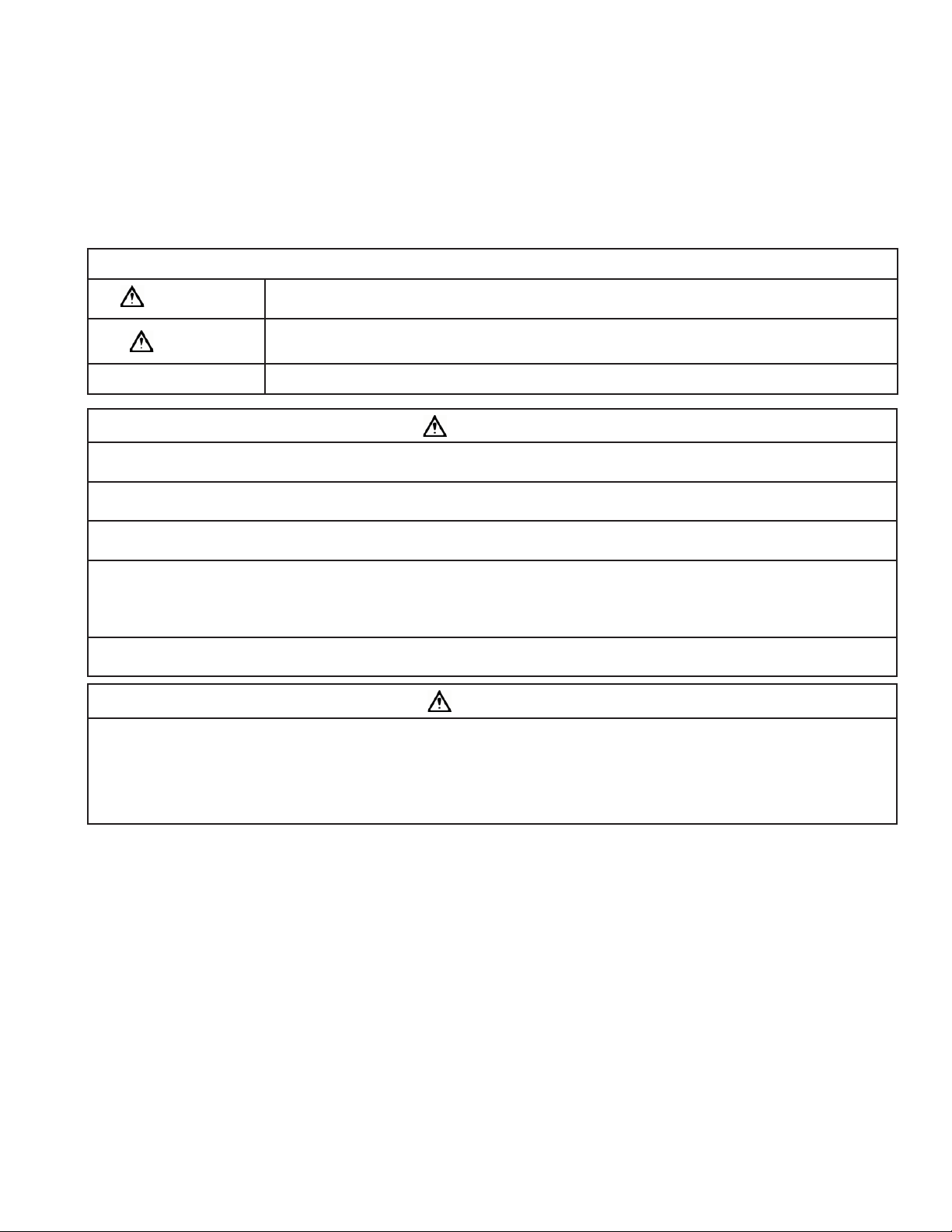
EXPLANATION OF SIGNAL WORD CONSEQUENCES
WARNING
CAUTION
Indicates a potentially hazardous situation, which, if not avoided, could result in death or serious injury and/or
property damage.
Indicates a potentially hazardous situation which, if not avoided, may result in minor or moderate injury and/or
property damage.
CAUTION
Indicates a potentially hazardous situation, which, if not avoided, may result in property damage.
WARNING
To reduce the risk associated with choking:
• Do not allow children under 3 years of age to have access to small parts during the installation of this product.
To reduce the risk associated with ingestion of contaminants:
• Do not use with water that is microbiologically unsafe or of unknown quality without adequate disinfection before or after the system.
To reduce the risk of physical injury:
• Shut off inlet water supply and depressurize system as shown in manual prior to service.
To reduce the risk associated with a hazardous voltage:
• If the electrical system requires use of the cold water system as an electrical safety ground, a jumper must be used to ensure a suffi cient ground connection
across the fi lter installation piping — refer installation to qualifi ed personnel.
• Do not use the system if the power cord is damaged — contact qualifi ed service personnel for repair.
To reduce the risk associated with back strain due to the heavy weight of the various system components:
• Follow safe lifting procedures.
CAUTION
To reduce the risk associated with skin, eye, and respiratory tract irritation from dust from fi lter media during installation:
• Gravel and several types of fi lter media may be used in this product, depending upon the application. During installation, dust may cause irritation to skin,
eyes, and respiratory tract, and may affect lungs.
• Utilize a NIOSH-approved dust fi lter mask and appropriate eye protection when handling and pouring gravel and fi lter media.
• To request an MSDS relating to this product, call 203-238-8965 or visit the web at http://solutions.3m.com/wps/portal/3M/en_US/MSDS (click MSDS
search). For emergencies, call 800-364-3577 or 651-737-6501 (24 hours).
Page 4

CAUTION
IMPORTANT NOTES
To reduce the risk associated with property damage due to water leakage:
• Read and follow Use instructions before installation and use of this water treatment system.
• Installation and use MUST comply with existing state or local plumbing codes.
• Protect from freezing, relieve pressure and drain system when temperatures are expected to drop below 33°F (0.6°C).
• Do not install on hot water supply lines. The maximum operating water temperature of this fi lter system is 110°F (43.3°C).
• Do not install systems in areas where ambient temperatures may go above 110°F (43.3°C) or below 40°F (4.4°C).
• Do not install if water pressure exceeds 100 psi. If your water pressure exceeds 80 psi (552 kPa), you must install a pressure limiting valve. Contact a
plumbing professional if you are uncertain how to check your water pressure.
• Do not install where water hammer conditions may occur. If water hammer conditions exist you must install a water hammer arrester. Contact a plumbing professional if you are uncertain how to check for this condition.
• Where a backfl ow prevention device is installed on a water system, a device for controlling pressure due to thermal expansion must be installed.
• Do not use a torch or other high temperature sources near fi lter system, cartridges, plastic fi ttings or plastic plumbing.
• On plastic fi ttings, never use pipe sealant or pipe dope. Use PTFE thread tape only, pipe dope properties may deteriorate plastic.
• Take care when using pliers or pipe wrenches to tighten plastic fi ttings, as damage may occur if over tightening occurs.
• Do not install in direct sunlight or outdoors.
• Mount system in such a position as to prevent it from being struck by other items used in the area of installation.
• Ensure all tubing and fi ttings are secure and free of leaks.
• SHUT OFF FUEL OR ELECTRIC POWER SUPPLY TO WATER HEATER after water is shut off.
• Do not install system where water lines could be subjected to vacuum conditions without appropriate measures for vacuum prevention.
• Do not apply heat to any fi tting connected to Bypass or Control Valve as damage may result to internal parts or connecting adapters.
• Install on a fl at/level surface. It is also advisable to sweep the fl oor to eliminate objects that could pierce the brine tank.
To reduce the risk associated with property damage due to plugged water lines:
• Pay particular attention to correct orientation of control valve. Water fl ow should match arrow on control valve. The Inlet and Outlet of other water treatment
equipment products will vary depending on the control valve brand used.
IMPORTANT NOTES
• Failure to follow instructions may result in leakage and will void warranty.
• Since some media dissolves as it elevates pH level, it will increase the hardness. If your dwelling is equipped with a tankless water heater, the
installation of a water softener may be necessary to prevent the heater coil from plugging.
Page 5

Page 6

IMPORTANT NOTE:
IMPORTANT NOTE
TABLE OF CONTENTS
SECTION DESCRIPTION
1 BEFORE INSTALLATION
2 INSTALLATION
3 MAINTENANCE
4 TROUBLESHOOTING
5 SPECIFICATION AND OPERATING DATA
WARRANTY
SECTION 1: BEFORE INSTALLATION
Inspecting And Handling Your Filter:
Inspect the equipment for shipping damage. If damaged, notify the transportation company and request a damage inspection.
Handle the fi lter with care. Damage can occur if dropped or set on sharp, uneven projections on the fl oor. Do not turn the fi lter upside down.
Make Sure Your Water Has Been Thoroughly Tested:
An analysis of your water should be made prior to the selection of your water conditioning equipment. Your dealer will generally perform this service for you,
and may send a sample to the factory for analysis and recommendations. Enter your below for a permanent record.
IMPORTANT NOTE:
Hydrogen sulfi de (H2S) must be tested for at the well site. For accuracy, the sample must be drawn with the pump RUNNING and the test be completed
within ONE minute after the sample is drawn.
Analysis Of Your Water
Hardness _____gpg
Iron (Fe) _____gpg
Manganese (Mn) _____ppm
pH _____
Tannins (Humic Acid) _____ppm
Hydrogen Sulfi de (H2S) _____ppm
Other_______________ _____
Other_______________ _____
There are several different fi lter media which can be used in this fi lter. Each is designed to improve a particular aesthetic problem. NONE OF THEM SHOULD
BE USED TO MAKE NON-POTABLE WATER SAFE TO DRINK. The following descriptions indicate not only what the media is designed to do, but also points out
their limitations.
Neutralizer
NEUTRALIZATION (C or N Media) helps prevent corrosion of copper pipes and plumbing fi xtures by correcting low pH (acidic) water conditions. This process
is similar to adding lime to acidic soil or to taking an antacid. C Media is used for moderate pH correction (pH 6.0 - 6.8). N Media, which dissolves more
rapidly, is used for more extreme conditions (pH 5.5 - 6.0 and as low as 5.0 under certain conditions). Both types of media are consumed during neutraliza-
tion and must be replenished periodically.
IMPORTANT NOTE
Since neutralizer media dissolves as it raises pH, it will increase the hardness. To help protect your water heater from the "scaling effect" of hard water,
a Scale Inhibitor Filter or Water Softener should be installed after the neutralizer.
1-1
Page 7

Activated Carbon
IMPORTANT NOTE
ACTIVATED CARBON ADSORPTION (A Media) is used to reduce chlorine, many impurities that give water an unpleasant taste or odor, and a wide variety of
organic chemicals, including most pesticides, herbicides, and solvents (consult with manufacturer when attempting to reduce specifi c chemical contaminants). Carbon contains millions of microscopic pores which chemically bond with these impurities to reduce them from the water. The capacity for adsorption is quite large but eventually the carbon must be replaced (the interval depends on the total quantity of impurities and amount of water used.)
Filtration Media
Filtration (F Media) is used when particle reduction is the only process required. The media is inert and does not react chemically with the water. GradedDensity media can be backwashed very effi ciently and is particularly effective for the reduction of precipitated iron.
Activated Carbon
Activated carbon is generally used to reduce objectionable tastes and odors from water, chlorine being the most common. Activated carbon works primarily on the concept of adsorption. Each particle of carbon has numerous pores through which the water passes. It is in these pores that the reduction of
unwanted constituents occurs. During backwash, these “collected” contaminants are knocked off and fl ushed away to drain. Since the pores in the carbon
are very important, the presence of sediment in the water — which can plug these pores — will greatly shorten the run time and life span of the carbon.
The chlorine is reduced by a chemical reaction on the surface of the activated carbon, where the chlorine ions in the water are reduced to chloride ions,
lessening the taste and odor issues associated with chlorine in the water.
The useful life of activated carbon will vary greatly depending on the water contaminants and amount of water fi ltered per day. Rarely will the carbon last
more than three (3) years.
Check Your Water Pressure And Pumping Rate:
Two water system conditions must be checked carefully to avoid unsatisfactory operation or equipment damage:
1) Minimum water pressure required at the fi lter tank inlet is 20 psi (138 kPa).
CAUTION
To reduce the risk associated with property damage due to water leakage:
• Do not install if water pressure exceeds 100 psi. If your water pressure exceeds 80 psi (552 kPa), you must install a pressure limiting valve. Contact a
plumbing professional if you are uncertain how to check your water pressure.
• Do not install where water hammer conditions may occur. If water hammer conditions exist you must install a water hammer arrester. Contact a plumbing
professional if you are uncertain how to check for this condition.
IMPORTANT NOTE
If you have a municipal or a community water supply and daytime water pressure is 85 psi (586 kPa) or more, nighttime pressure may exceed 100 psi (689 kPa).
Call your local water department or plant operator to obtain pressure readings. If you have a private well, the gauge on the pressure tank will indicate high and
low system pressure. Record your water pressure data below:
Water Pressure
Low _________psi High _________psi
2) The pumping rate of your well pump must be suffi cient for satisfactory BACKWASH. Although the density of a media normally determines the backwash
rate, all the media discussed earlier will require the same fl ow rate. These models require a 5 gpm rate (refer to SPECIFICATIONS AND OPERATING DATA
for the backwash requirement for other models). To measure the pumping rate of your pump, follow these instructions:
a. Make certain no water is being drawn. Open spigot nearest pressure tank. When pump starts, close spigot and measure time (in seconds) to refi ll
pressure tank (when pump shuts off). This fi gure represents CYCLE TIME.
b. With the pressure tank full, draw water into a container of known volume, measure the number of gallons drawn until the pump starts again. This
is DRAW-DOWN. Divide this fi gure by CYCLE TIME and multiply by 60 to arrive at the PUMPING RATE in gallons per minute (gpm). To aid in you
calculation, insert the data in the following formula:
DRAW-DOWN ______ ÷ CYCLE TIME ______ x 60 = PUMPING RATE ______
(gals.) (secs.) (gpm)
EXAMPLE: CYCLE TIME is 63 secs.; DRAWDOWN is 8 gals.; then PUMPING RATE equals:
8 gals. ÷ 63 secs. x 60 = 7.6 gpm
1-2
Page 8

Locate Water Conditioning Equipment Correctly:
Select the location of your backwash system with care. Various conditions which contribute to proper location are as follows:
1) Locate as close as possible to water supply source.
2) Locate as close as possible to a drain.
3) Locate in correct relationship to other water conditioning equipment (Figure 1).
4) Locate the backwash system in the supply line BEFORE the water heater. Temperatures above 110°F (43.3°C) will damage the backwash system
and void the factory warranty.
5) DO NOT install the backwash system in a location where freezing temperatures occur. Freezing may cause permanent damage and will also void
the factory warranty.
6) Allow suffi cient space around the installation for easy servicing.
7) Provide a non-switched 110V, 60Hz (220V, 50Hz for specifi ed systems) power source for the control valve.
WARNING
To reduce the risk associated with ingestion of contaminants:
• Do not use with water that is microbiologically unsafe or of unknown quality without adequate disinfection before or after the system.
CAUTION
To reduce the risk associated with property damage due to water leakage:
• Protect from freezing, relieve pressure and drain system when temperatures are expected to drop below 33°F (0.6°C).
• Do not install on hot water supply lines. The maximum operating water temperature of this fi lter system is 110°F (43.3°C).
• Do not install systems in areas where ambient temperatures may go above 110°F (43.3°C) or below 40°F (4.4°C).
The Importance Of Your Pressure Tank:
A properly sized pressure tank will require a minimum pump cycle of 60 seconds to refi ll from pump on-to-off pressure settings.
NOTE: If your pressure tank (or any part of your water system) is not functioning properly, corrective action MUST be taken before installation of your fi lter.
Facts to Remember While Planning Your Installation:
1) All installation procedures MUST conform to local and state plumbing codes.
2) If lawn sprinkling, a swimming pool, or geothermal heating/cooling or water for other devices/activities are to be treated by the backwash system,
a larger model MUST be selected to accommodate the higher fl ow rate plus the backwashing requirements of the backwash system. Consult your
dealer for alternative instructions if the pumping rate is insuffi cient.
3) Remember that the backwash system INLET is attached to the pipe that supplies water (i.e. runs to the pump) and the OUTLET is the line that runs
toward the water heater.
CAUTION
To reduce the risk associated with property damage due to plugged water lines:
• Pay particular attention to correct orientation of control valve. Water fl ow should match arrow on control valve. The Inlet and Outlet of other water treatment
equipment products will vary depending on the control valve brand used.
4) Before commencing the installation it is advisable to study the existing piping system and to determine the size, number and type of fi ttings
required.
WARNING
To reduce the risk associated with a hazardous voltage:
• If the electrical system requires use of the cold water system as an electrical safety ground, a jumper must be used to ensure a suffi cient ground connection across
the fi lter installation piping — refer installation to qualifi ed personnel.
5) It is also advisable to sweep the fl oor to eliminate objects that could pierce the brine tank.
1-3
Page 9

SECTION 2: INSTALLATION
CAUTION
Proper installation sequence of Filter System is very important. Refer to the diagram following for your particular supply.
FILTERED WATER
FILTERED
SOFT WATER
WATER FOR
LAWN SPRINKLERS
OR OTHER
HIGH DEMAND
BRINE
MAKER
SOFTENER
PUBLIC WATER SUPPLY INSTALLATION
To reduce the risk associated with property damage due to plugged water lines:
• Pay particular attention to correct orientation of control valve. Water fl ow should match arrow on control valve. The Inlet and Outlet of other water treatment
equipment products will vary depending on the control valve brand used.
FILTER
Figure 1 Installation Sequence
CAUTION
CHECK VALVE
METER
RAW
WATER
2-1
Page 10

Step 1
IMPORTANT NOTE
CAUTION
CAUTION
CAUTION
(a) Remove the control valve by removing the latch and clamp and pulling the valve up and out of the tank. Before loading
the media into the tank, the distributor must be all the way to the bottom of the tank. It is therefore recommended that the
distributor be removed and the gravel dumped out and saved. The distributor tube should then be replaced in the empty
tank making sure it rests on the bottom. Use the plastic cap provided to plug the distributor tube and prevent media from
entering the distributor. Material lodge in the distributor tube can enter the control valve, thus damaging it. First, pour the
gravel removed earlier back into the media tank and then add the media. Utilize the centering tool to help keep the distributor tube centered in the mineral tank opening to aid in mounting the control over the distributor tube. Never add media to
a level above the line on the side of the tank. Additional media may have been shipped for future replenishment.
(b) Fill the tank with water. Lubricate o-ring on tank adapter with silicone grease and reinstall the CONTROL VALVE. Make sure
the distributor tube fi ts into the valve body tube adapter protruding from the bottom of the valve body.
(c) Reinstall clamp. Align the "LATCH" arrows on the clamp body (see FIGURE 2).
(d) If the BYPASS VALVE/YOKE ASSEMBLY is not factory pre-installed, attach to back of CONTROL VALVE using ADAPTER COU-
PLINGS, CLIPS and SCREWS.
IMPORTANT NOTE
Never add media above line indicated on side of tank. You may have received more media than required for the initial
fi ll, save extra media for future replenishment.
CAUTION
To reduce the risk associated with skin, eye, and respiratory tract irritation from dust from fi lter media during installation:
• Gravel and several types of fi lter media may be used in this product, depending upon the application. During installation, dust may cause irritation to
skin, eyes, and respiratory tract, and may affect lungs.
• Utilize a NIOSH-approved dust fi lter mask and appropriate eye protection when handling and pouring gravel and fi lter media.
• To request an MSDS relating to this product, call 203-238-8965 or visit the web at http://solutions.3m.com/wps/portal/3M/en_US/MSDS (click MSDS
search). For emergencies, call 800-364-3577 or 651-737-6501 (24 hours).
Figure 2. LATCH
Step 2
Shut off water at main supply. On a private well systems, turn off power to pump and drain pressure tank. Make certain pressure is relieved from complete system
by opening nearest faucet to drain system.
CAUTION
To reduce the risk associated with property damage due to water leakage:
• SHUT OFF FUEL OR ELECTRIC POWER SUPPLY TO WATER HEATER after water is shut off.
Step 3
Cut main supply line as required to fi t plumbing to Inlet and Outlet of Bypass Valve Assembly.
Step 4
Solder or solvent weld plumbing. Do not apply heat to any fi tting connected to bypass or control
valve as damage may result to internal parts or connecting adapters. Make certain water fl ow
enters through inlet and discharges through outlet.
CAUTION
To reduce the risk associated with property damage due to water leakage:
• Do not use a torch or other high temperature sources near fi lter system, cartridges,
plastic fi ttings or plastic plumbing.
• On plastic fi ttings, never use pipe sealant or pipe dope. Use PTFE thread tape only, pipe
dope properties may deteriorate plastic.
• Take care when using pliers or pipe wrenches to tighten plastic fi ttings, as damage may
occur if over tightening occurs.
To reduce the risk associated with property damage due to plugged water lines:
• Pay particular attention to correct orientation of control valve. Water fl ow should match arrow on control valve. The Inlet and Outlet of other water treatment equipment products will
vary depending on the control valve brand used.
ADAPTER YOKE
ADAPTER COUPLING
CLIP &
SCREW
SERVICE
Figure 3 . INLET/OUTLET CONNECTIONS
OUT IN
BYPASS
ROTATE
KNOBS
BYPASS VALVE
DRAIN LINE
BYPASS
FITTING
BYPASS
2-2
Page 11

Step 5
CAUTION
IMPORTANT NOTE
IMPORTANT NOTE
IMPORTANT NOTE
Attach Drain Line to Drain Line Fitting. To prevent back pressure from reducing the fl ow rate below minimum required for backwash, Drain Line MUST be sized
according to run length and relative height. Be careful not to bend fl exible drain tubing sharply enough to cause “kinking” (if kinking occurs Drain Line MUST be
replaced). Typical examples of proper Drain Line diameters are:
a. 1/2” ID lengths up to 15 feet and heights lower or slightly higher than the control valve.
b. 5/8” ID length up to 25 feet in length and up to 4 feet above the control valve.
c. For distances higher or longer than previously stated, relocate the fi lter closer to the desired discharge point or consult
factory for advice. Avoid overhead drain lines as it may prevent desirable performance.
Avoid installing drain overhead or using fl exible vinyl tubing, either may result in failure.
Some areas prohibit the use of fl exible drain lines. Check with local code offi cials prior to installation.
CAUTION
To reduce the risk associated with property damage due to water leakage:
• Installation must comply with existing state or local plumbing codes..
Figure 4. DRAIN
Step 6
Position Drain Line over drain and secure fi rmly. To prevent back-siphoning of sewer water, provide an air-gap of at least 2 inches or 2 pipe diameters between
end of drain hose and drain (See Figure 4). Do not raise Drain Line more than 10 feet above fl oor.
Step 7
Make certain both inlet and outlet knobs of bypass valve are in "bypass" position. Turn on power to well pump or completely open main supply valve. Check for
leaks and correct as necessary.
Step 8
a) Manually stage control to Backwash Position (See “How To Manually Backwash Your Filter At Any Time”, Page 2-4). Open Bypass Valve approximately 1/4 of
the way to full open (“Service” Position), allowing unit to fi ll slowly. This will purge entrapped air in the bed.
b) Once a steady stream of water is fl owing to drain, open Bypass Valve completely. Leave unit in backwash for at least 10 minutes OR until drain line water
runs clear, whichever is longer.
IMPORTANT NOTE
Filters containing activated carbon or F media must be saturated for at least 2 hours prior to subjecting the unit to full backwash fl ow rates. Failure to do this
may result in loss of mineral during initial backwash procedure.
Step 9
After this preliminary backwash, manually advance Control Valve to “Service” position and plug valve into a 110V, 60Hz properly grounded non-switched power
source.
Step 10
Set time of day (See How To Set Time Control) and set Backwash Frequency (See Determining Backwash Frequency). Installation is now complete.
IMPORTANT NOTE
During the initial backwashings, a small amount of media may be observed in drain water. This is normal and benefi cial for effi cient operation of your fi lter
system.
Step 11
Manually initiate a complete “regeneration” process, allowing the unit to automatically proceed through a backwash and rapid rinse. See “How to Manually Backwash Your Filter At Any Time.” Check drain water at end of rapid rinse cycle. If water is cloudy, repeat the backwash process.
IMPORTANT NOTE
Restore Fuel Supply or power to Water Heater.
Determining Backwash Frequency
The exact backwash frequency depends on the quality of the raw water, but it is recommended that fi lters containing Activated Carbon, Birm, Filter Ag or Filter Sand be
programmed to backwash at least once every six days. If pressure drop becomes excessive or contaminant reappears in the treated water before six days, increase
the frequency. Filters containing Neutralizer should be backwashed every other day to prevent the media particles from “cementing” together. See “How to Set Time
Control” for procedure.
2-3
Page 12

HOW TO SET TIME CONTROL
IMPORTANT NOTE
IMPORTANT NOTE
RED TIME-SET
BUTTON
TO SET TIME OF DAY - PRESS RED
BUTTON AND TURN LARGE GEAR UNTIL
PRESENT TIME APPEARS ABOVE ARROW.
FOR MANUAL REGENERATION TURN KNOB
CLOCKWISE TO REGEN. POSITION.
MANUAL REGENERATION
KNOB
SERVICE
12
DAY
TIME OF
TIME OF DAY
ARROW
How To Set Time Of Day
12 HOUR GEAR
6
5
RED POINTER
SKIPPER WHEEL
(SHOWS EVERY DAY
REGENERATION)
2
3
4
1) Press and hold the red button in to disengage the drive gear.
2) Turn the large gear until the actual time of day shows in the time of day window. Unit will now be set to backwash at 1:00 a.m. (See note below to adjust
the time).
3) Release the red button to again engage the drive wheel.
How To Set The Skipper Wheel
If you are setting the Time Control after Midnight but before Noon, the red pointer on the Skipper Wheel must be between two numbers (as shown). If you are
setting the Time Control after Noon, but before Midnight, the red pointer must be covering one of the numbers. Setting the Skipper Wheel in this manner will
provide a 1:00 a.m. Backwashing time.
IMPORTANT NOTE
If directions above on How To Set The Skipper Wheel are not followed, Backwashing will not take place at the appropriate time of day.
How To Set Days On Which Filter Is To Backwash
Set the days that backwash is to occur by sliding tabs on the skipper wheel outward to expose trip fi ngers. Each tab is one day. Extend or retract fi ngers to obtain the desired backwashing schedule. Typically, these units are backwashed every third day. Consult your dealer for their recommendations for your water.
How To Manually Backwash Your Filter At Any Time
Turn the manual backwash knob clockwise until the knob engages the program wheel. This slight movement of the knob will start the backwash program.
The backwash knob will make one revolution in approximately 1 1/2 hours and stop in the position shown in the drawing. Even though it takes 1 1/2 hours for
the knob to complete one revolution, the backwash cycle of your unit might be about 20 minutes in duration.
In any event, fi ltered water may be drawn after rinse water stops fl owing from the fi lter drain line.
IMPORTANT NOTE
Should it be necessary to change the time of day which backwash is to start, the time on 12 hour gear must be altered. For example, if 2:00 a.m. is desired
instead of 1:00 a.m., set the 12 hour gear one hour earlier than actual time.
2-
Page 13

CAUTION
SECTION 3: MAINTENANCE
1) At least every six months you should check the time of day setting. Power outages will cause the unit to lose time.
2) If your unit contains Activated Carbon, you must replace the carbon and gravel underbed at least every three (3) years. Replacement may be required
sooner if the taste and odor being reduced reappears in the treated water or pressure drop due to fouling of the media becomes excessive.
3) Filtration media will last an indefi nite period of time. It may be necessary to replace it, if the pressure drop across the fi lter becomes too great or fi ltration
results drop.
4) Neutralizer media, (C or N) must be replenished at least annually. Measure down from the top of the tank, comparing the current level with the mark. If
the level is down by more than three (3) inches, add media
To Replenish (Rebed) Media
Pressure must be relieved on system by turning both Inlet and Outlet knobs of Bypass Valve to “Bypass” position and manually rotating Control Valve to “Backwash” position.
(a) Remove the control valve by removing the latch and clamp and pulling the valve up and out of the tank. Before loading the media into the tank, the dis-
tributor must be all the way to the bottom of the tank. It is therefore recommended that the distributor be removed and the gravel dumped out and saved.
The distributor tube should then be replaced in the empty tank making sure it rests on the bottom. Use the plastic cap provided to plug the distributor
tube and prevent media from entering the distributor. Material lodge in the distributor tube can enter the control valve, thus damaging it. First, pour the
gravel removed earlier back into the media tank and then add the media. Utilize the centering tool to help keep the distributor tube centered in the mineral
tank opening to aid in mounting the control over the distributor tube. Never add media to a level above the line on the side of the tank. Additional media
may have been shipped for future replenishment.
(b) Fill the tank with water. Lubricate o-ring on tank adapter with silicone grease and reinstall the CONTROL VALVE. Make sure the distributor tube fi ts into
the valve body tube adapter protruding from the bottom of the valve body.
(c) Reinstall clamp. Align the "LATCH" arrows on the clamp body (see FIGURE 2).
(d) If the BYPASS VALVE/YOKE ASSEMBLY is not factory pre-installed, attach to back of CONTROL VALVE using ADAPTER COUPLINGS, CLIPS and SCREWS.
CAUTION
To reduce the risk associated with skin, eye, and respiratory tract irritation from dust from fi lter media during installation:
• Gravel and several types of fi lter media may be used in this product, depending upon the application. During installation, dust may cause irritation to
skin, eyes, and respiratory tract, and may affect lungs.
• Utilize a NIOSH-approved dust fi lter mask and appropriate eye protection when handling and pouring gravel and fi lter media.
• To request an MSDS relating to this product, call 203-238-8965 or visit the web at http://solutions.3m.com/wps/portal/3M/en_US/MSDS (click MSDS
search). For emergencies, call 800-364-3577 or 651-737-6501 (24 hours).
3-1
Page 14

PROBLEM CAUSE SOLUTION
1 Excessive pressure drop
through fi lter
2 Contaminant not being
properly reduced.
3 Filter raises pH too high
(Neutralizer)
4 Filter fails to raise pH
(Neutralizer)
SECTION 4: TROUBLESHOOTING
A Filter not backwashing 1 Check motor by manually initiating a regeneration, re-
place as necessary
2 Check for uninterrupted power supply.
3 Check backwash frequency. Change program if neces-
sary.
B Filter bed loaded with sand. 1 Verify sediment being reduced is less dense than the
fi lter media.
C “Cementing” or “Channeling” of media. 1 Probe bed for this condition. Verify adequate pumping
rate for backwashing.
2 Check for frozen, plugged or restricted drain line.
3 Check for adequate backwash frequency.
D Top Screen Fouled 1 Remove screen and clean as necessary.
A Leaking bypass valve. 1 Check bypass valve in “SERVICE” position. Repair or re-
place if necessary.
B Internal valve leak. 1 Check piston and spacers and seals. Replace as neces-
sary.
C Distributor not properly seated in control valve. 1 Make sure distributor is in tube adaptor protruding from
bottom of control valve.
2 Check distributor tube o-ring. Replace as necessary.
D Flow rate too high for fi lter. 1 Check demand requirements against fi lter recommend-
ed fl ow rates.
A Filter is brand new. 1 Crack the bypass valve allowing some water to bypass
the unit.
B Wrong media used. 1 Rebed unit.
A Flow rates too high. 1 Verify demand rate does not exceed fi lter rating.
B Filter bed cemented or channeled. 1 Verify adequate pumping rate for backwashing unit.
2 Check drain line for freezing, plugging or restrictions.
4-1
Page 15

SECTION 5: SPECIFICATION & OPERATING DATA
ITEM CFS101BWF CFS151BWF CFS201BWF
Filter Media Volume, cu.ft. (cu.mtr.) 1.0 (0.03) 1.5 (0.05) 2.0 (0.06)
Gravel Underbed, lbs. (kg.) 18 (8.2) 18 (8.2) 22 (10.0)
Operating Flow Rate, gpm (lpm) (Note 1):
Continuous (no duration limit) 3 (11) 3 (11) 4 (15)
Service (10 mins. or less) 5 (19) 6 (23) 7 (26)
Backwash Flow Rate, gpm (lpm) (Note 2) 5 (19) 5 (19) 7 (26)
Service Pipe Size, in. (cm.) 1 (2.54) 1 (2.54) 1 (2.54)
Tank Diameter x Height, in. (cm.) 10 x 44
(25 x 112)
Minimum Space Required, in. (cm.):
Width 12 (31) 12 (31) 12 (31)
Depth 18 (46) 18 (46) 18 (46)
Height 56 (142) 66 (168) 66 (168)
Approximate Shipping Weight, lbs. (kg.) l/media 45 (20) 51 (23) 57 (26)
10 x 54
(25 x 137)
12 x 54
(31 x 137)
Maximum operating temperature 110º F (43.3º C)
Electrical requirements 110V/60Hz
Operating pressure 20-100 psi.
Specifi cations are subject to change without notice.
NOTES:
1) For satisfactory performance, indicated durations should not be exceeded. Flow rates specifi ed are adequate for normal residential applications. Do not
use Service fl ow rates when sizing commercial applications or if treated water is to supply a geothermal heat pump, swimming pool, etc.
2) For system to operate properly, pumping rate of well pump MUST be suffi cient to backwash unit at rate specifi ed.
5-1
Page 16

COMPONENT PARTS LIST
Ref No. Description
1 Control Valve w/cover, l/Bypass N200500 N200500 N200700
2 Adapter Assy., Flange-Thrd (Incl. Ref. 3) 55640-130 55640-130 55640-130
3 O-ring ORG-234 ORG-234 ORG-234
4 Clamp Assy. 55640-131 55640-131 55640-131
9 Top Screen 13700 13700 13700
10 Media Tank w/Base MTP1044FB MTP1054FB MTP1252FB
11 Media (Various Types) (1.0 CF) (1.5 CF) (2.0 CF)
12 Distributor C37-16-41 C37-16-51 C37-16-51
13 Gravel Underbed 68696-37 68696-37 68686-38
NOTE: When ordering components, always specify model number.
NBW1001 NBW1501 NBW2001
10
1
12
9
2
4
3
11
13
5-2
Page 17

BACKWASH CONTROL
5-3
Page 18

ONLY THOSE PARTS CIRCLED IN DRAWING ON PREVIOUS PAGE AND/OR LISTED BELOW ARE STOCK ITEMS.
ALL OTHERS ARE SPECIAL ORDER, NON-RETURNABLE.
BACKWASH CONTROL PARTS LIST
REF PART NO> DESCRIPTION
60351-00 Power Head Assy., Complete, L/Cover, 110V,60Hz (Incl. Ref. Items 1-27)
A
60351-04 Power Head Assy., Complete, L/Cover, 220V,50Hz (Incl. Ref. Items 1-27)
B 19231X Skipper Wheel Assy. (incl. Ref. Items 4-9)
C 19235X 12-Hour Gear Assy. (Incl. Ref. Items 10-15)
D 14554X Control Valve Body Assy. (Incl. Ref. Items 30-36 E & G)
E 60102-52 Piston Assembly
F 60125 Seal Kit (incl. Ref. items 32& 33)
G 60384X Drain Line Flow Control Assy. (incl. Ref. Items 37-44)
H 10090X Adapter Coupling Assy. (incl. Ref. Items 45-48)
60049/18706X 1" NPT Bypass Valve Assy. (incl. Ref. Items 49-58)
J
60049/18706-10X 1" BSP Bypass Valve Assy. (incl. Ref. Items 49-58)
19170 Motor, 110V, 60 Hz
23
18825 Motor, 220V,50Hz
24 11384 Motor Mtg. & Ground Screw
19171 Main Drive Gear
27
28 13547 Strain Relief - Flat Cord
29 11842 Power Cord, 110V,60Hz, US Plug
12972 Power Cord, 220V,50Hz, European Plug
35 13304 Distributor Tube O-Ring 1"
36 12281 Tank O-Ring
37 13303 Injector Cover O-Ring
38 13301 Injector O-Ring
39 13163 Injector/Drain Housing
40 13166 Injector Cover
41 13315 Injector Mtg. Screw
Drain Line Flow Control Button:
42
12092 5.0 GPM
12408 7.0 GPM
43 13173 Drain Line Flow Control Button Retainer
44 12338 Drain Line Fitting
45 13305 Coupling O-Ring
46 13709 Adapter Coupling
47 13255 Adapter Clip
48 13314 Screw - Adapter Coupling
49 18660 O-ring
50 18661 O-ring (ORG-218)
18706 Adapter Yoke, 1" NPT
51
18706-10X Adapter Yoke, 1" BSP
5-4
Page 19

Page 20

LIMITED WARRANTY
For any warranty questions, please refer to the enclosed warranty card or call 1-800-222-7880 or mail your request to:
CUNO Incorporated
400 Research Parkway
Meriden, CT 06450
© 2009 3M Company. All rights reserved.
3M is a trademark of 3M Company.
INSTR4333 0709
CUNO Incorporated
400 Research Parkway
Meriden, CT 06450, USA
Toll Free: 1.888.218.CUNO
Worldwide: 203.237.5541
Fax: 203.238.8701
www.cunofoodservice.com
 Loading...