

Page 1
Certifi ed to Certifi ed by
ANSI Z359.4 : 2013
DBI SALA
ROLLGLISS TECHNICAL RESCUE
NFPA 1983 : 2017
Lic. BMP 689957
BSI Certied Product
1
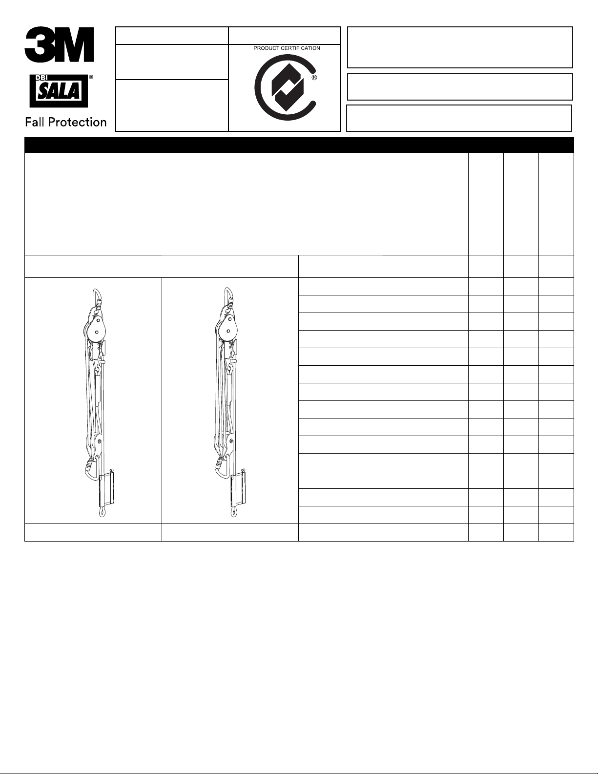
Part Number 1 2 3
8704103
8704104
8704105
8704106
8704107
8704108
8704109
8705103
8705104
8705105
8705106
8705107
8705108
8705110
8704XXX 8705XXX 8705113
Riggersmate Hauling Kits
USER INSTRUCTION MANUAL
Working Length (m)
Rope length (m)
5 25 4:1
10 50 4:1
15 75 4:1
20 100 4:1
30 150 4:1
40 200 4:1
50 250 4:1
2 14 6:1
10 70 6:1
15 105 6:1
20 140 6:1
25 175 6:1
30 210 6:1
40 280 6:1
5 35 6:1
Mechanical Advantage
Form No: A019 Rev: A
© 3M 2018
Page 2
2
A B C D E F
3 4
A
FC
B
C
FC
B
C
5 6
ABC
2
Page 3
7
1
2
ENGAGED
DISENGAGED
Rollgliss Technical Rescue
4:1 and 6:1 Autolock Hauling Kits
XXXXXXXXXX
ANSI Z359.4: 2013
NFPA 1983: 2017 G
Lic. BMP 689957
Lic QEC0022
MBS: 36kN
Quality
ISO 9001
DO NOT DISASSEMBLE.
OR 8700025.
Made in Australia
WLL: 59-282kg (130-620lb)
MEETS THE MANUFACTURED SYSTEM REQUIREMENTS OF NFPA
1983, STANDARD ON LIFE SAFETY ROPE AND EQUIPMENT FOR
EMERGENCY SERVICES, 2017 EDITION.
TO BE COMPLIANT WITH NFPA 1983, THE FOLLOWING
ADDITIONAL COMPONENTS MUST BE USED IN
CONJUNCTION WITH THIS MANUFACTURED SYSTEM:
2X 8700568 KARABINER AND PULLEY 8700027
8
8700027
Max Load: 282kg
MBS: 36kN
Max Load: 282kg
MBS: 36kN
8700025
Rollgliss Technical Rescue
6:1 Autolock Hauling Kit
Rollgliss Technical Rescue
4:1 Autolock Hauling Kit
3
Page 4

9
3M Australia Pty Limited
Part No.:
Standard: NFPA 1983
3M.com.au/FallProtection
DESCRIPTION
ID :
Inspect prior to use as per the manufacturer’s instruction
Manufacturer’s instruction shall be followed at all times
95 Derby St, Silverwater, 2128, NSW Australia
S/No.:
F/Order No.:
D.O.M.:
Destroy Before:
4
Page 5

SAFETY INFORMATION
Please read, understand, and follow all safety information contained in these instructions prior to the use of this Pre-
Engineered Rescue System. FAILURE TO DO SO COULD RESULT IN SERIOUS INJURY OR DEATH.
These instructions must be provided to the user of this equipment. Retain these instructions for future reference.
Intended Use:
This Pre-Engineered Rescue System is intended for use as part of a complete personal fall protection and/or rescue system.
Use in any other application including, but not limited to, material handling, recreational or sports related activities, or other activities not
described in the User Instructions, is not approved by 3M and could result in serious injury or death.
This system is only to be used by trained users in workplace applications.
! WARNING
This Pre-Engineered Rescue System is intended for use as part of a complete personal fall protection and/or rescue system. It is expected
that all users be fully trained in the safe installation and operation of their Pre-Engineered Rescue System. Misuse of this system
could result in serious injury or death. For proper selection, operation, installation, maintenance, and service, refer to these User
Instructions and all manufacturer recommendations, see your supervisor, or contact 3M Technical Service.
• To reduce the risks associated with working with a Pre-Engineered Rescue System which, if not avoided, could result
in serious injury or death:
- Inspect the system before each use and at least annually. Inspect in accordance with the User Instructions.
- If inspection reveals an unsafe or defective condition in the device or a component of the device, remove the device from service
and repair or replace according to the User Instructions.
- Label the system ‘UNUSABLE’ and immediately remove the system from service if it has been subjected to fall arrest or impact
force. Inspect and handle the system according to the User Instructions.
- Ensure the rescue system and lifeline are kept free from all obstructions including, but not limited to, entanglement with other
workers, yourself, and surrounding objects.
- Follow all manufacturer recommendations when connecting a lifeline.
- When performing rescue operations, always utilize fall protection safety measures as determined by your workplace rescue plan.
- Do not touch parts of devices exposed to high friction during or after long descents, as these parts may get hot and cause burns.
- Ensure proper edge protection is used if the lifeline may contact sharp edges or corners.
- Ensure a clear descent path, and that the landing area is clear of any obstructions or hazards that you may contact.
- Ensure that systems/subsystems assembled from components made by different manufacturers are compatible and meet
the requirements of applicable standards, including the ANSI Z359 or other applicable fall protection codes, standards, or
requirements. Always consult a Competent and/or Qualifi ed Person before using these systems.
• To reduce the risks associated with working at height which, if not avoided, could result in serious injury or death:
- Ensure your health and physical condition allow you to safely withstand all of the forces associated with working at height.
Consult with your doctor if you have any questions regarding your ability to use this equipment.
- Never exceed allowable capacity of your fall protection equipment.
- Never exceed maximum free fall distance of your fall protection equipment.
- Do not use any fall protection equipment that fails pre-use or other scheduled inspections, or if you have concerns about the use
or suitability of the equipment for your application. Contact 3M Technical Services with any questions.
- Some subsystem and component combinations may interfere with the operation of this equipment. Only use compatible
connections. Consult 3M prior to using this equipment in combination with components or subsystems other than those described
in the User Instructions.
- Use extra precautions when working around moving machinery (e.g. top drive of oil rigs) electrical hazards, extreme
temperatures, chemical hazards, explosive or toxic gases, sharp edges, or below overhead materials that could fall onto you or
the fall protection equipment.
- Use Arc Flash or Hot Works systems when working in high heat environments.
- Avoid surfaces and objects that can damage the user or equipment.
- Ensure there is adequate fall clearance when working at height.
- Never modify or alter your fall protection equipment. Only 3M or parties authorized in writing by 3M may make repairs to the
equipment.
- Prior to use of fall protection equipment, ensure a rescue plan is in place which allows for prompt rescue if a fall incident occurs.
- If a fall incident occurs, immediately seek medical attention for the fallen worker for the worker who has fallen.
- Do not use a body belt for fall arrest applications. Use only a Full Body Harness.
- Minimize swing falls by working as directly below the anchorage point as possible.
- If training with this device, a secondary fall protection system must be utilized in a manner that does not expose the trainee to
an unintended fall hazard.
- Always wear appropriate personal protective equipment when installing, using, or inspecting the device/system.
EN
FORM NO: 5908259 REV: A
5
Page 6

Before using this equipment, record the product identifi cation information from the ID label in the “Inspection and
Maintenance Log” at the back of this manual.
DESCRIPTION
Figure 1 defi nes the different confi gurations of Riggersmate Hauling Kit. Figure 10 defi nes the components of the Hauling Kit:
A. HEAD UNIT
B. TRAVEL ASSEMBLY
C. ROPE (TAIL END)
D. ROPE (LOADED END)
E. TOP PULLEY
F. LOCKING CAM
G. CAM FOLLOWER
H. ROPE GUIDE
I. LABEL PACK
J. INSPECTION TAG ATTACHMENT POINT
K. ROPE TERMINATION
L. TOP ATTACHMENT KARABINER
M. TRAVEL ATTACHMENT KARABINER
10
L
A
E
D
SPECIFICATIONS
Performance:
NFPA 1983 General
Minimum Breaking strength 36 kN (8093 lb)
C
G
F
H
K
B
J
M
I
Materials:
Rope Polyester/Nylon orange with black fl eck
Stitching Polyester
Label Cover Nylon Black
Karabiner Steel, Yellow zinc plate MBS 53kN (11914 lb), Gate 16kN (3600 lb)
Head unit and travel Aluminium 6000 series, Stainless steel
6
Page 7

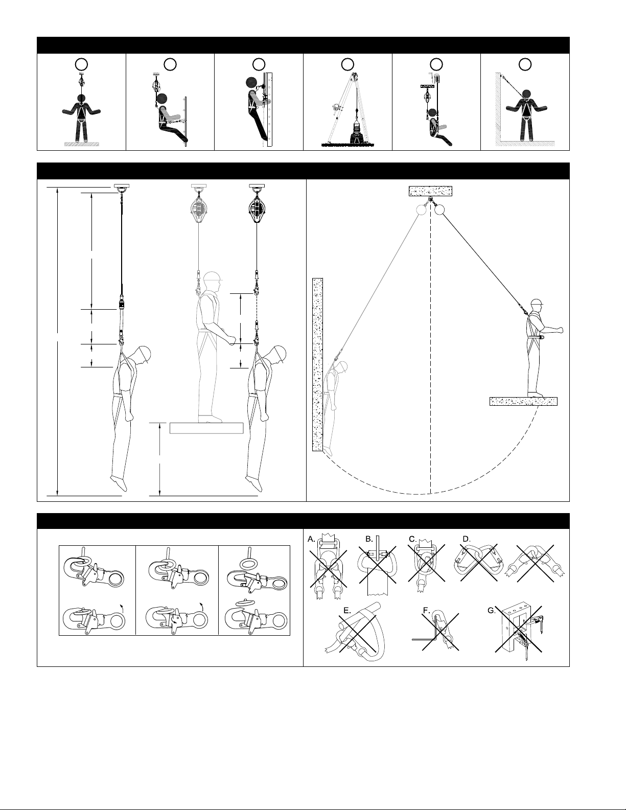
1.0 APPLICATIONS
1.1 PURPOSE: Hauling Kits are to be used as components in Personal Fall Protection Systems, designed to provide
mechanical advantage for raising or lowering a load. More information on hauling kits and engineered systems can be
found in NFPA 1500 and NFPA 1983. Also refer to ANSI Z359.1, Z359.4 and local governing regulations for safe rescue
operations. Hauling Kits are typically used as part of a Rescue or Controlled Descent system (see Figure 2):
Fall Arrest (AS/NZS1891.4): Personal fall arrest systems typically include a Full Body Harness and a connecting subsystem
A
(Energy Absorbing Lanyard, Self-Retracting Device, etc.). Maximum arresting force must not exceed 6 kN (1,349 lb). Maximum
free fall distance 2m (6.6 ft). Anchorage Strength: Selected anchorage must sustain loads of 15 kN (3,372 lb) for single person use
or 21kN (4721 lb) or greater for 2 person use.
Work Positioning (AS/NZS1891.4): Work positioning systems typically include a Full Body Harness, positioning lanyard, and a
B
back-up personal fall arrest system. For work positioning applications, connect the work positioning subsystem (example: lanyard,
Y-lanyard, etc.) to the lower (hip level) side or belt mounted work positioning attachment anchorage elements (D-Rings). Never
use these connection points for fall arrest. Maximum free fall distance 0.6m (2 ft)Anchorage Strength: Selected anchorage must
sustain loads of 12 kN (2698 lb) for single person use or 18kN (4047 lb) or greater for 2 person use.
Climbing (AS/NZS1891.3): The Full Body Harness is used as a component of a climbing system to prevent the user from falling
C
when climbing a ladder or other climbing structure. Climbing systems typically include a Full Body Harness, vertical cable or rail
attached to the structure, and climbing sleeve. For ladder climbing applications, harnesses equipped with a frontal D-Ring in the
sternal location may be used for fall arrest on fi xed ladder climbing systems. Sternal. Anchorage Strength: Structure to which the
climbing system is attached must sustain the loads required by the climbing system manufacturer’s documentation.
Rescue: Rescue systems are confi gured depending on the type of rescue. For limited access (confi ned space) applications,
D
harnesses equipped with D-Rings on the shoulders may be used for entry and egress into confi ned spaces where worker profi le is
an issue.
Controlled Descent: For controlled descent applications, harnesses equipped with a single sternal level D-Ring, one or two
E
frontal mounted D-Rings, or a pair of connectors originating below the waist (such as a seat sling) may be used for connection to a
descent or evacuation system.
Restraint (AS/NZS1891.4): The Full Body Harness is used as a component of a restraint system to prevent the user from
F
reaching a fall hazard. Restraint systems typically include a Full Body Harness and a lanyard or restraint line.
1.2 STANDARDS: The Hauling Kits included in this manual conform to the standard(s) identifi ed on the front cover of
this instruction. If this product is resold outside the original country of destination, the re-seller must provide these
instructions in the language of the country in which the product will be used.
1.3 TRAINING: It is the responsibility of the user and the purchaser of this equipment to assure that they are familiar with
these instructions, trained in the correct care and use of, and are aware of the operating characteristics, application limits,
and the consequences of improper use of this equipment.
1.4 LIMITATIONS: Always consider the following application limitations before using this equipment:
• CAPACITY: The Hauling Kit is rated to 59-282kg (130-620lb), minimum breaking strength of 36 kN (8093 lb). Make
sure all of the components in your system are rated to a capacity appropriate to your application.
• FREE FALL: Personal fall arrest systems used with this equipment must be rigged to limit the free fall to 2 m (6.6 ft)1.
Restraint systems must be rigged so that no vertical free fall is possible. Work positioning systems must be rigged so
that free fall is limited to 0.6 m (2 ft) or less. Personnel riding systems must be rigged so that no vertical free fall is
possible. Climbing systems must be rigged so that free fall is limited to 0.46 cm (18 in) or less. Rescue systems must
be rigged so that no vertical free fall is possible. See subsystem manufacturer’s instructions for more information.
• FALL CLEARANCE: Figure 3 illustrates the components of a Fall Arrest. There must be suffi cient Fall Clearance (FC)
to arrest a fall before the user strikes the ground or other obstruction. Clearance is affected by a number of factors
including: (A) Lanyard Length, (B) Lanyard Deceleration Distance or SRL Maximum Arrest Distance, (C) Harness
Stretch and D-Ring/Connector Length and Settling (typically a Safety Factor of 1 m (3.3 ft). Refer to the instructions
included with your Fall Arrest subsystem for specifi cs regarding Fall Clearance calculation.
• SWING FALLS: Swing Falls occur when the anchorage point is not directly above the point where a fall occurs (see Figure
4). The force of striking an object in a swing fall may cause serious injury or death. Minimize swing falls by working as
directly below the anchorage point as possible. Do not permit a swing fall if injury could occur. Swing falls will signifi cantly
increase the clearance required when a Self-Retracting Device or other variable length connecting subsystem is used.
• EXTENDED SUSPENSION: A Full Body Harness is not intended for use in extended suspension applications. If the
user is going to be suspended for an extended length of time it is recommended that some form of seat support be
used. 3M recommends a seat board, suspension work seat, seat sling, or a boatswain chair. Contact 3M for more
information on these items.
• ENVIRONMENTAL HAZARDS: Use of this equipment in areas with environmental hazards may require additional
precautions to prevent injury to the user or damage to the equipment. Hazards may include, but are not limited to;
heat, chemicals, corrosive environments, high voltage power lines, gases, moving machinery, and sharp edges.
• ENVIRONMENT: This equipment is design for use between -40° and 60°Celsius (-40 and 140° F).
1 Fall Arrest Free Falls: Free falls greater than 2 m (6.6 ft) may be permitted when users are secured to the anchorage with a connecting subsystem which limits
maximum arresting force to 6 kN (1,349 lb) and is authorized for such use (i.e., 3M Force 2™ Lanyards).
7
Page 8

2.0 SYSTEM USE
2.1 RESCUE PLAN: When using this equipment and connecting subsystem(s), the employer must have a rescue plan and the
means at hand to implement and communicate that plan to users2, authorized persons3, and rescuers4.
2.2 INSPECTION FREQUENCY:
other than the user at intervals of no more than 12 months6. Inspection procedures are described in the User Instruction
Manual’s “Inspection and Maintenance Log”. Results of each Competent Person inspection should be recorded on copies of
the “Inspection and Maintenance Log” . If the unit is dropped or impact-load during use the product should be removed from
service and inspected by a competent person immediately.
Where required by 3M, due to complexity or innovation of the equipment; or where critical knowledge is needed
in dismantling, reassembly, or assessment of the equipment, periodic examinations shall only be conducted by 3M or
persons or organizations authorised by 3M.
2.3 COMPATIBILITY OF COMPONENTS: 3M equipment is designed for use with 3M approved components and subsystems
only. Substitutions or replacements made with non-approved components or subsystems may jeopardize compatibility of
equipment and may effect the safety and reliability of the complete system.
2.4 COMPATIBILITY OF CONNECTORS: Connectors are compatible with connecting elements when they have been
designed to work together in such a way that their sizes and shapes do not cause their gate mechanisms to inadvertently
open regardless of how they become oriented. Contact 3M if you have any questions about compatibility. Connectors
(hooks, carabiners, and D-Rings) must be capable of supporting at least 22.2 kN (5,000 lb). Connectors must be
compatible with the anchorage or other system components. Do not use equipment that is not compatible. Noncompatible connectors may unintentionally disengage (See Figure 5). Connectors must be compatible in size, shape,
and strength. If the connecting element to which a snap hook (shown) or carabiner attaches is undersized or irregular in
shape, a situation could occur where the connecting element applies a force to the gate of the snap hook or carabiner.
This force may cause the gate to open, allowing the snap hook or carabiner to disengage from the connecting point. Selflocking snap hooks and carabiners are required.
2.5 MAKING CONNECTIONS: Use only self-locking snap hooks and carabiners with this equipment. Use only connectors that
are suitable for each application. Ensure all connections are compatible in size, shape and strength. Do not use equipment
that is not compatible. Ensure all connectors are fully closed and locked.
3M connectors (snap hooks and carabiners) are designed to be used only as specifi ed in each product’s user’s instructions.
See Figure 6 for inappropriate connections. 3M snap hooks and carabiners should not be connected:
A. To a D-Ring to which another connector is attached.
B. In a manner that would result in a load on the gate.
C. In a false engagement, where features that protrude from the snap hook or carabiner catch on the anchor, and
without visual confirmation seems to be fully engaged to the anchor point.
D. To each other.
E. Directly to webbing or rope lanyard or tie-back (unless the manufacturer’s instructions for both the lanyard and
connector specifically allows such a connection).
F. To any object which is shaped or dimensioned such that the snap hook or carabiner will not close and lock, or that
roll-out could occur.
G. In a manner that does not allow the connector to align properly while under load.
2.6 CONNECTING SUBSYSTEMS: Connecting subsystems (self-retracting lifeline, lanyard, rope grab and lifeline, cable sleeve,
etc.) must be suitable for your application (See section 1.1). See the subsystem manufacturer’s instructions for additional
information.
The Hauling Kit shall be inspected by the user before each use and by a competent person5
2 User: A person who performs activities at heights while protected by a personal fall protection system.
3 Authorized Person: A person assigned by the employer to perform duties at a location where the person will be exposed to a fall hazard.
4 Rescuer: Person or persons other than the rescue subject acting to perform an assisted rescue by operation of a rescue system.
5 Competent Person: One who is capable of identifying existing and predictable hazards in the surroundings or working conditions which are unsanitary, hazardous,
or dangerous to employees, and who has authorization to take prompt corrective measures to eliminate them.
6 Inspection Frequency: Extreme working conditions (harsh environments, prolonged use, etc.)may require increasing the frequency of competent person inspec-
tions.
8
Page 9

3.0 INSTALLATION AND USE
3.1 BEFORE EACH USE of this equipment inspect it according to the “Inspection and Maintenance Log” (Table 1).
3.2 PLAN your system before use. Consider all factors that will affect your safety during use of this equipment. The following
list gives important points to consider when planning your system:
• Anchorage: Select an anchorage capable of sustaining the Static Load requirements of the intended fall protection
application (see Section 1.1). The anchorage location should address Free Fall, Fall Clearance, Swing Fall, and
Environmental limitations described in Section 1.4.
• Sharp Edges: Avoid working where system components may be in contact with, or abrade against, unprotected
sharp edges.
• After A Fall: Components which have been subjected to the forces of arresting a fall must be removed from service
and destroyed.
• Rescue: The employer must have a rescue plan when using this equipment. The employer must have the ability to
perform a rescue quickly and safely.
• Rescue Harness: Rescue Harnesses are intended to be worn during normal work activities. Before using rescue
attachment elements for the fi rst time, the user should carry out a suspension test in safe conditions to ensure the
harness is sized and fi tted for optimal comfort during suspension.
3.3 ANCHORAGE REQUIREMENTS: The Riggersmate Hauling Kits should be attached to a suitable anchorage or anchorage
connector capable of supporting the required loads. As per AS/NZS 5532: 2013 the anchorage connector should be rated
to a minimum of 12kN for single person use and 18kN for 2 person use.
3.4 INSTALLATION REQUIREMENTS:
1. Attach the Hauling Kit to a suitable anchorage connector as per section 3.3, using the connector provided
on the head unit.
2. The travel assembly end of the device can then be attached to the load using the connector provided.
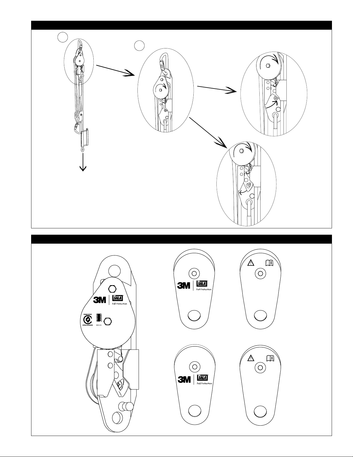
3.5 RAISING:
1. Raise a load by pulling the tail end of the rope.
2. Whilst the load is being raised, the locking cam will engaged and disengaged once every revolution of the
top pulley, making a clicking sound.
3. Continue pulling the tail end of the rope until the load reaches the required position.
4. Slow release the tail end of the rope. If the rope tail tries to pull back through the device, raise the load
another 50mm to engage the locking cam.
5. The travel assembly should never be raise to interfere with the rope termination.
3.6 LOWERING:
1. To lower the load, pull on the tail end of the rope until the locking cam disengages.
2. Slowly allow the tail end of the rope be pulley back through the device by the raise load.
3. To stop lowering, pull on the tail end of the rope and raise the load 50mm to engage to locking cam.
3.7 MAKING CONNECTIONS: When using a hook to connect to an anchorage or when coupling components of the system
together, ensure roll-out cannot occur. Roll-out occurs when interference between the hook and mating connector causes
the hook gate to unintentionally open and release. Self-locking snap hooks and carabiners should be used to reduce the
possibility of roll-out. Do not use hooks or connectors that will not completely close over the attachment object. See
subsystem manufacturer’s instructions for more information on making connections.
3.8 OVER-SPEED LOCK: All Riggersmate Hauling Kits are equipped with an internal over-speed lock. If at any point during
operation the load becomes uncontrolled or the tail end of the rope released, this feature will automatically lock and
prevent the load from falling to the ground. If the over-speed lock is activated, follow the lowering procedure, section
3.6, to continue operation. As soon as possible after an over-speed lock the unit shall be inspected as per section 5 of this
manual. Do not continue to use this product after an over-speed lock unless completing a rescue.
9
Page 10

4.0 INSPECTION
4.1 INSPECTION FREQUENCY: The Hauling Kit must be inspected at the intervals defi ned in Section 2.2. Inspection
procedures are described on the “Inspection and Maintenance Log” (Table 1).
4.2 DEFECTS: If inspection reveals a defective condition, is deemed unsuitable for use by a competent person or has been
involved in a fall, remove unit from service immediately and destroy.
4.2 PRODUCT LIFE: The functional life of Hauling Kit is determined by work conditions and maintenance. As long as the
product passes inspection criteria, it may remain in service for up to 10 years from the date of manufacture.
5.0 MAINTENANCE, SERVICING, STORAGE
5.1 CLEANING INSTRUCTIONS: Clean the Rollgliss Technical Rescue Hauling Kit as follows:
A) Wash Haul Kits in clean water only. Attention should be given to the locking cam and cam follower to ensure any
grit is removed and they are moving smoothly. If you need to remove grit or more stubborn dirt and grime that often
causes stiffness in the operation of the cam, a light cleaning agent such as WD40 or equivalent may be used. When
a cleaning agent is used, ensure that all remnants are washed off and that the cleaning agent does not come into
contact with the rope.
B) After washing, dry the unit with a soft cloth and hang the rope in a well ventilated area out of direct sunlight, to
allow for proper drying.
C) Inspect Riggersmate Hauling Kits as per the inspection section within this manual. If the unit fails inspection or
there is concern about its condition, return the unit to 3M Fall Protection and or their authorised service agent for
service.
D) Store dry units within their supplied bag in a clean and dry location.
5.2 AUTHORISED SERVICE: Additional maintenance and servicing procedures must be completed by a factory authorised
service center. Authorisation must be in writing. Do not attempt to alter the unit in any way.
5.3 STORAGE AND TRANSPORT: Store and transport the Hauling Kit in a cool, dry, clean environment out of direct sunlight.
Avoid areas where chemical vapors may exist. Thoroughly inspect the Hauling Kit after extended storage.
6.0 LABELING:
Figures 8 and 9 illustrate product markings and labels and their location on the Hauling Kit. All markings and labels must
be present and fully legible.
10
Page 11

Table 1 – Inspection and Maintenance Log
Serial Number(s): Date Purchased:
Model Number: Date of First Use:
Inspection Date: Inspected By:
Component: Inspection: (See Section 2.2 for Inspection Frequency) User Competent
Rope and Stitching Inspect rope; material must be free of frayed, cut, or broken fi bers. Check for tears, abrasions, mold,
Labels and markings All labels and marking should be present and fully legible. See fi gures 8 and 9.
burns, or discoloration. Inspect stitching; Check for pulled, cut or broken stitches.
Person
Head unit Inspect top pulley is free to rotate in both directions. When rotating clockwise the cam follower plate
Travel Assembly 8700025 or
8700027
Karabiners 8700568 Inspect the body for the Karabiner for wear, abrasion, deformation, rust (corrosion) and deterioration. .
System & Subsystem
Components
should rotate in synchronous with the pulley, when rotating counter clockwise the cam follower plate
should remain stationary. Inspect the top pulley and lower pulleys are free of foreign material. Inspect
the cam and cam follower are free of foreign material and is free to move. Inspect the cam teeth are
sharp and grip the rope. Inspect all components for wear, abrasion, deformation, rust (corrosion) and
deterioration.
Inspect the sheaves of the pulley are free to rotate and free of foreign material. Inspect all components
for wear, abrasion, deformation, rust (corrosion) and deterioration.
Inspect the gate opens and auto closes freely.
Inspect each system component or subsystem according to the manufacturer’s instructions. Inspect each
system component or subsystem is compatible with this equipment.
Corrective Action/Maintenance: Approved By:
Date:
Next Inspection:
Corrective Action/Maintenance: Approved By:
Date:
Next Inspection:
Corrective Action/Maintenance: Approved By:
Date:
Next Inspection:
Corrective Action/Maintenance: Approved By:
Date:
Next Inspection:
Corrective Action/Maintenance: Approved By:
Date:
Next Inspection:
Corrective Action/Maintenance: Approved By:
Date:
Next Inspection:
Corrective Action/Maintenance: Approved By:
Date:
Next Inspection:
11
Page 12

3M AUSTRALIA PTY LTD & 3M NEW ZEALAND LTD (“3M”)
LIMITATION OF LIABILITY
To the extent permitted by law, 3M’s liability and the liability of the person who
sold you this product, is limited at 3M’s option, to the repair or replacement of the
goods or the refund of the purchase price of the goods. 3M will not be liable for
any Equipment damage resulting from wear, abuse, damage in transit, failure to
maintain the product or other damage beyond the control of 3M.
Except to the extent that such liability is not able to be excluded by law, all other
liability of 3M whether arising from negligence or otherwise is expressly excluded.
For the avoidance of doubt, except where required by the Australian Consumer
Law or any other law that cannot be excluded, 3M will not be liable for any
indirect, special, incidental or consequential loss (including, but not limited to, loss
of profi ts, and the costs of inspection, testing, storage or transportation).
3M reserves the right to require that the Equipment be returned to its plant for
inspection before determining the appropriate course of action.
USA
3833 SALA Way
Red Wing, MN 55066-5005
Toll Free: 800.328.6146
Phone: 651.388.8282
Fax: 651.388.5065
3Mfallprotection@mmm.com
Brazil
Rua Anne Frank, 2621
Boqueirão Curitiba PR
81650-020
Brazil
Phone: 0800-942-2300
falecoma3m@mmm.com
Mexico
Calle Norte 35, 895-E
Col. Industrial Vallejo
C.P. 02300 Azcapotzalco
Mexico D.F.
Phone: (55) 57194820
mexico@capitalsafety.com
Colombia
Compañía Latinoamericana de Seguridad S.A.S.
Carrera 106 #15-25 Interior 105 Manzana 15
Zona Franca - Bogotá, Colombia
Phone: 57 1 6014777
fallprotection-co@mmm.com
3M.com/FallProtection
Canada
260 Export Boulevard
Mississauga, ON L5S 1Y9
Phone: 905.795.9333
Toll-Free: 800.387.7484
Fax: 888.387.7484
3Mfallprotection-ca@mmm.com
EMEA (Europe, Middle East, Africa)
EMEA Headquarters:
5a Merse Road
North Moons Moat
Redditch, Worcestershire
B98 9HL UK
Phone: + 44 (0)1527 548 000
Fax: + 44 (0)1527 591 000
informationfallprotection@mmm.com
France:
Le Broc Center
Z.I. 1re Avenue - BP15
06511 Carros Le Broc Cedex
France
Phone: + 33 04 97 10 00 10
Fax: + 33 04 93 08 79 70
informationfallprotection@mmm.com
Australia & New Zealand
95 Derby Street
Silverwater
Sydney NSW 2128
Australia
Toll-Free : 1800 245 002 (AUS)
Toll-Free : 0800 212 505 (NZ)
3msafetyaucs@mmm.com
Asia
Singapore:
1 Yishun Avenue 7
Singapore 408731
Phone: +65 - 65587758
Fax: +65 - 65587058
totalfallprotectio@mmm.com
Shanghai:
19/F, L’Avenue, No.99 Xian Xia Rd
Shanghai 200051, P R China
Phone: +86 21 62539050
Fax: +86 21 62539060
3MFallProtecton-CN@mmm.com
Quality
ISO 9001
Environment
ISO 14001
 Loading...