

Page 1

3
3M-Matic
800rf Type 39800
Automatic Random Case Sealer with
AccuGlide
II Taping Heads
Service Manual
Printed in U.S.A.
3M Packaging Systems Division Copyright © 1999, 3M IPC.
3M Center, Building 220-8W-01 3M-Matic and AccuGlide are trademarks of 3M, All rights reserved.
St. Paul, MN 55144-1000 St. Paul, MN 55144-1000 78-8114-0965-1 Rev. B
Page 2

Page 3

Replacement Parts and Service Information
To Our Customers:
This is the 3M-Matic/AccuGlide/Scotch brand equipment you ordered.
It has been set up and tested in the factory with Scotch brand tapes.
If technical assistance or replacement parts are needed, call or Fax the
appropriate number listed below.
Technical Assistance
3M-Match Helpline − 1-800/328 1390. Please provide the customer support
coordinator with the machine number, machine type/model and serial number.
If you have a technical question that does not require an immediate response,
you may Fax it to 715/381 0248.
Replacement Parts
Order parts by part number, part description and quantity required. Also include
machine name, number and type. A parts order form is provided at the end of
Section 7 of this manual, Illustrated Parts Breakdown.
3M/Tape Dispenser Parts
241 Venture Drive 1-800/344 9883
Amery, WI 54001-1325 FAX# 715/268 8153
Minimum billing on parts orders will be $25.00. Replacement part prices available on request.
Note: Outside the U.S., contact the local 3M subsidiary for parts ordering information.
$10.00 restocking charge per invoice on returned parts.
3
3M Packaging Systems Division
3M Center, Building 220-8W-01
St. Paul, MN 55144-1000
Page 4

Replacement Parts and Service Information
To Our Customers:
This is the 3M-Matic/AccuGlide/Scotch brand equipment you ordered.
It has been set up and tested in the factory with Scotch brand tapes. If
any problems occur when operating this equipment, and you desire a service call, or phone consultation, call, write, or Fax the appropriate number
listed below.
SERVICE AND PARTS AVAILABLE DIRECT FROM:
Order parts by part number, part description and quantity required. Also include
machine name, number and type.
3
3M Packaging Systems Division
3M Center, Building 220-8W-01
St. Paul, MN 55144-1000
Page 5

3M-Matic 800rf Case Sealer Revision History
3M-Matic 800rf Service Manual
Revision History
The original issue of this manual and subsequent revisions are identified as follows:
Issue date (Rev. A): 12/98, (Rev. B): 9/99
Revision B revised pages include:
Page Date
Title Page 9/99
Revision History 9/99
vi 9/99
5-3 through 5-8 9/99
5-11, 5-12 9/99
5-21 9/99
7-5 9/99
7-8 through 7-11 9/99
7-18 through 7-20 9/99
7-40 9/99
7-42 9/99
7-48 9/99
7-54 9/99
7-56 through 7-58 9/99
7-61 9/99
7-65 9/99
A-i 9/99
A-13 through A-42 9/99
Copyright 1999, 3M IPC. All rights reserved. i
Page 6

Revision History 3M-Matic 800rf Case Sealer
This page intentionally left blank.
ii Copyright 1999, 3M IPC. All rights reserved.
Page 7

3M-Matic 800rf Case Sealer Table of Contents
Section 1. Description and Specifications
1-1. Intended Use ............................................................................................................................................. 1-1
1-2. Description ............................................................................................................................................... 1-2
1-3. Specifications ........................................................................................................................................... 1-3
1-4. Case Sealing Rate Approximation Formula .............................................................................................1-4
1-5. Machine Dimensions ................................................................................................................................1-5
Section 2. Installation
2-1. General ..................................................................................................................................................... 2-1
2-2. Unpacking................................................................................................................................................. 2-2
2-3. Setup Procedure ........................................................................................................................................ 2-3
2-3-1. Case Sealer Bed Height ............................................................................................................... 2-3
2-3-2. Rear Emergency Stop Switch Installation ................................................................................... 2-3
2-3-3. Warning Beacon Installation ....................................................................................................... 2-4
2-3-4. Pneumatic Connection................................................................................................................. 2-4
2-3-5. Air Pressure Indicator.................................................................................................................. 2-5
2-3-6. Air Pressure Regulators ............................................................................................................... 2-5
2-3-7. Electrical Connection .................................................................................................................. 2-6
2-4. Tape Loading ............................................................................................................................................2-8
2-4-1. Top Tape Head Loading ..............................................................................................................2-9
2-4-2. Bottom Tape Head Loading.......................................................................................................2-10
2-5. Tape Drum Friction Brake...................................................................................................................... 2-11
2-6. Checkout Inspection (to be performed by an authorized 3M Service Technician) ................................ 2-11
2-6-1. Static Tests ................................................................................................................................. 2-11
2-6-2. Programmable Controller Inputs and Outputs...........................................................................2-15
2-6-3. Dynamic Tests ...........................................................................................................................2-19
2-7. Placing 800rf Case Sealer in Production Line ....................................................................................... 2-20
2-8. Special Setup Procedure .........................................................................................................................2-21
2-8-1. Relocating Pneumatic and Electrical Control Panels ................................................................2-21
Section 3. Adjustments
3-1. Case Sealer Bed Height ............................................................................................................................3-1
3-2. Pneumatic Device Factory Set Points ...................................................................................................... 3-2
3-3. Main Air Pressure Regulator ....................................................................................................................3-4
3-4. Box Centering Pressure Regulator ........................................................................................................... 3-4
3-5. Side Belt Pressure Regulator .................................................................................................................... 3-5
3-6. Side Belts Closure Drive Chain................................................................................................................ 3-5
3-7. Side Belts In/Out Rates ............................................................................................................................ 3-6
3-8. Side Belt Inner Limit ................................................................................................................................3-7
3-9. Side Belt Tension...................................................................................................................................... 3-8
3-10. Motor Drive Belts, Upper and Lower ...................................................................................................... 3-9
3-11. Drive Chain ............................................................................................................................................ 3-10
3-12. Safety Door Interlock ............................................................................................................................. 3-10
3-13. Flap Folder Arm and Flap Folder Flow Controls - Speed Controls ....................................................... 3-11
3-14. Flap Folder Arm Reed Switch ................................................................................................................ 3-12
3-15. Cylinder Cushion Setting ....................................................................................................................... 3-13
3-16. Paddle Pressure Regulator ...................................................................................................................... 3-13
Copyright 1999, 3M IPC. All rights reserved. iii
Page 8

Table of Contents 3M-Matic 800rf Case Sealer
3-17. Counter-Balance Pressure Regulator...................................................................................................... 3-14
3-18. Case Top Sensitivity ............................................................................................................................... 3-14
3-19. Fork Cylinder Flow Controls - Speed Controls...................................................................................... 3-15
3-20. Infeed Box Stop-Gate Flow Control - Speed Control ............................................................................ 3-16
3-21. Box Centering Rails In/Out Rates .......................................................................................................... 3-17
3-22. Upper Head Assembly Down/Up Rates ................................................................................................. 3-18
3-23. Top Flap Compression Rollers ...............................................................................................................3-19
3-24. Tape Web Alignment .............................................................................................................................. 3-19
3-25. Tape Drum Friction Brake...................................................................................................................... 3-20
3-26. Tape Applying Mechanism Spring ......................................................................................................... 3-20
3-27. One-Way Tension Roller ........................................................................................................................ 3-21
3-28. Low Air Pressure Switch ........................................................................................................................3-22
3-29. Overload Circuit Breaker ....................................................................................................................... 3-23
3-30. Head Travel Limit Switch ...................................................................................................................... 3-23
Section 4. Disassembly/Reassembly
4-1. General ..................................................................................................................................................... 4-1
4-2. Format....................................................................................................................................................... 4-1
4-3. Side Drive Belt Assembly ........................................................................................................................ 4-2
4-4. Side Drive Belt ......................................................................................................................................... 4-3
4-5. Motor Drive Belts, Upper and Lower ...................................................................................................... 4-4
4-6. Case Sealer Bed Plates ............................................................................................................................. 4-6
4-7. Fork Cylinder............................................................................................................................................ 4-7
4-8. Side Drive Belts Cylinder......................................................................................................................... 4-7
4-9. Flap Folder Cylinder ................................................................................................................................ 4-8
4-10. Flap Folder Arm Cylinder ........................................................................................................................ 4-8
4-11. Knife Replacement, Upper Taping Head ..................................................................................................4-9
4-12. Knife Replacement, Lower Taping Head ............................................................................................... 4-10
4-13. Belt Drive Pulley Assembly Ribbed Rings ............................................................................................ 4-10
4-14. Infeed Rollers ......................................................................................................................................... 4-12
4-15. Overload Circuit Breaker ....................................................................................................................... 4-14
Section 5. Theory of Operation
5-1. General ..................................................................................................................................................... 5-1
5-2. Operation Summary.................................................................................................................................. 5-1
5-2-1. Random Mode ............................................................................................................................. 5-1
5-2-2. Fixed Mode ................................................................................................................................. 5-2
5-2-3. Bypass Mode ............................................................................................................................... 5-2
5-3. Sequence Tables ....................................................................................................................................... 5-2
5-4. Electrical System ....................................................................................................................................5-14
5-4-1. Power Distribution ....................................................................................................................5-14
5-4-2. Special Circuits/Components ....................................................................................................5-14
5-4-3. Electrical Schematic ..................................................................................................................5-16
5-5. Pneumatic System .................................................................................................................................. 5-20
Pneumatic Diagram ................................................................................................................... 5-21
iv Copyright 1999, 3M IPC. All rights reserved.
Page 9

3M-Matic 800rf Case Sealer Table of Contents
Section 6. Troubleshooting
6-1. General ..................................................................................................................................................... 6-1
6-2. Troubleshooting Guide ............................................................................................................................. 6-1
6-3. Pneumatic Component Testing .................................................................................................................6-6
6-4. Electrical Circuit Fault Conditions ........................................................................................................... 6-8
Section 7. Illustrated Parts Breakdown
7-1. How to Order Replacement Parts .............................................................................................................7-1
7-2. Spare Parts ................................................................................................................................................7-1
7-3. Suggested Spare Parts .............................................................................................................................. 7-1
7-4. Illustrations and Parts Lists ...................................................................................................................... 7-2
Figure 7-1. 800rf Case Sealer Breakdown .............................................................................................. 7-2
Figure 7-2. Conveyor Frame ................................................................................................................... 7-4
Figure 7-3. Conveyor Center Bed and Fork ............................................................................................ 7-8
Figure 7-4. Conveyor Bed Rollers......................................................................................................... 7-10
Figure 7-5. Side Belt Centering .............................................................................................................7-12
Figure 7-6. Column Assembly ...............................................................................................................7-16
Figure 7-7. Flap Folder Assembly ......................................................................................................... 7-18
Figure 7-8. Paddle Assembly................................................................................................................. 7-22
Figure 7-9. Side Belt Rail Assembly ..................................................................................................... 7-24
Figure 7-10. Head Cylinder Assembly .................................................................................................. 7-26
Figure 7-11. Upper Tape Head Mount................................................................................................... 7-28
Figure 7-12. Upper Tape Drum Bracket Assembly ............................................................................... 7-30
Figure 7-13. Side Belt and Drive Assemblies ....................................................................................... 7-32
Figure 7-14. Side Belt Drive Pulleys (Detail) ....................................................................................... 7-36
Figure 7-15. Upper Head Conduit Assembly ........................................................................................ 7-38
Figure 7-16. Electrical Control Panel ....................................................................................................7-40
Figure 7-17. Electrical Control Panel (Detail) ...................................................................................... 7-44
Figure 7-18. Pneumatic Control Panel .................................................................................................. 7-46
Figure 7-19. Pneumatic Components, #1 .............................................................................................. 7-48
Figure 7-20. Pneumatic Components, #2 .............................................................................................. 7-50
Figure 7-21. Pneumatic Components, #3 .............................................................................................. 7-52
Figure 7-22. Sliding Door Assembly .....................................................................................................7-56
Figure 7-23. Infeed Conveyor Frame .................................................................................................... 7-60
Figure 7-24. Infeed Conveyor Drive Assembly ..................................................................................... 7-64
Figure 7-25. Infeed Conveyor Centering Assembly .............................................................................. 7-66
Figure 7-26. Taping Head Assemblies - AccuGlide
Figure 7-27. Frame Assembly for Upper Head ..................................................................................... 7-72
Figure 7-28. Applying Assembly for Upper and Lower Heads ............................................................. 7-74
Figure 7-29. Buffing Assembly for Upper Head ................................................................................... 7-76
Figure 7-30. Link Assembly for Upper and Lower Heads ....................................................................7-78
Figure 7-31. Knife Assembly for Upper and Lower Heads................................................................... 7-80
Figure 7-32. Tape Drum and Bracket for Upper and Lower Heads ...................................................... 7-82
Figure 7-33. Frame Assembly for Lower Head ..................................................................................... 7-84
Figure 7-34. Buffing Assembly for Lower Head ...................................................................................7-86
II STD 2-Inch ................................................... 7-70
Copyright 1999, 3M IPC. All rights reserved. v
Page 10

Table of Contents 3M-Matic 800rf Case Sealer
Section 8. Preventative Maintenance
8-1. General ..................................................................................................................................................... 8-1
8-1-1. Maintenance ................................................................................................................................ 8-1
8-1-2. Tool Kit ....................................................................................................................................... 8-1
8-2. Cleaning.................................................................................................................................................... 8-1
8-3. Lubrication ............................................................................................................................................... 8-2
8-3-1. Taping Heads ............................................................................................................................... 8-2
8-3-2. Main Assembly and Infeed Assembly ......................................................................................... 8-2
8-4. Maintenance Schedule.............................................................................................................................. 8-4
8-4-1. Taping Heads ............................................................................................................................... 8-4
8-4-2. Infeed Assembly .......................................................................................................................... 8-4
8-4-3. Main Assembly ............................................................................................................................ 8-5
Appendix A. PLC Addendum
A-1. SLC 500 Controller Description ............................................................................................................. A-1
A-2. SLC 500 Specifications ........................................................................................................................... A-1
A-3. Programming ........................................................................................................................................... A-4
A-4. Troubleshooting....................................................................................................................................... A-4
A-5. Ladder Logic Diagram .......................................................................................................................... A-13
A-6. Cross Reference..................................................................................................................................... A-36
A-7. Replacement Parts ................................................................................................................................. A-40
A-8. Documentation ...................................................................................................................................... A-41
vi Copyright 1999, 3M IPC. All rights reserved.
Page 11
3M-Matic 800rf Case Sealer Safety Information
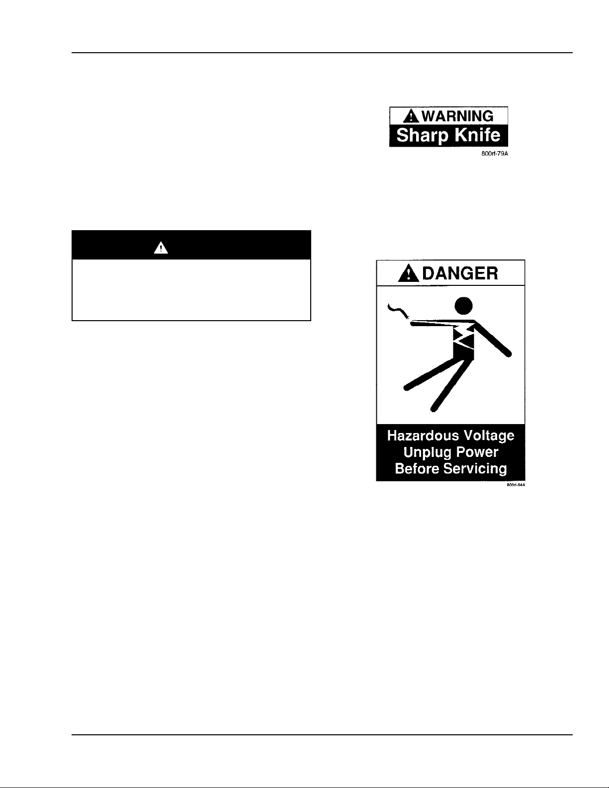
Warning Label
The WARNING Sharp Knife label, shown in
Figure 1, is attached to the orange cut-off knife
guard on both taping heads. The label warns the
operator and service personnel of the very sharp
knife located behind the guard and to keep hands
out of this area except for tape loading and servicing
the taping heads.
Warning
The taping heads are equipped with an
orange knife guard that covers the knife.
The taping heads must never be operated
with the knife guards removed.
Figure 1. Warning Label
Danger Label
The DANGER Hazardous Voltage Unplug Power
Before Servicing label, shown in Figure 2, is
attached to the front of the Electrical Control Panel,
at the front of the machine. When power is on,
opening the panel door allows access to +24 VDC
and 220 VAC.
Figure 2. Danger Label
Copyright 1999, 3M IPC. All rights reserved. vii
Page 12
Safety Information 3M-Matic 800rf Case Sealer
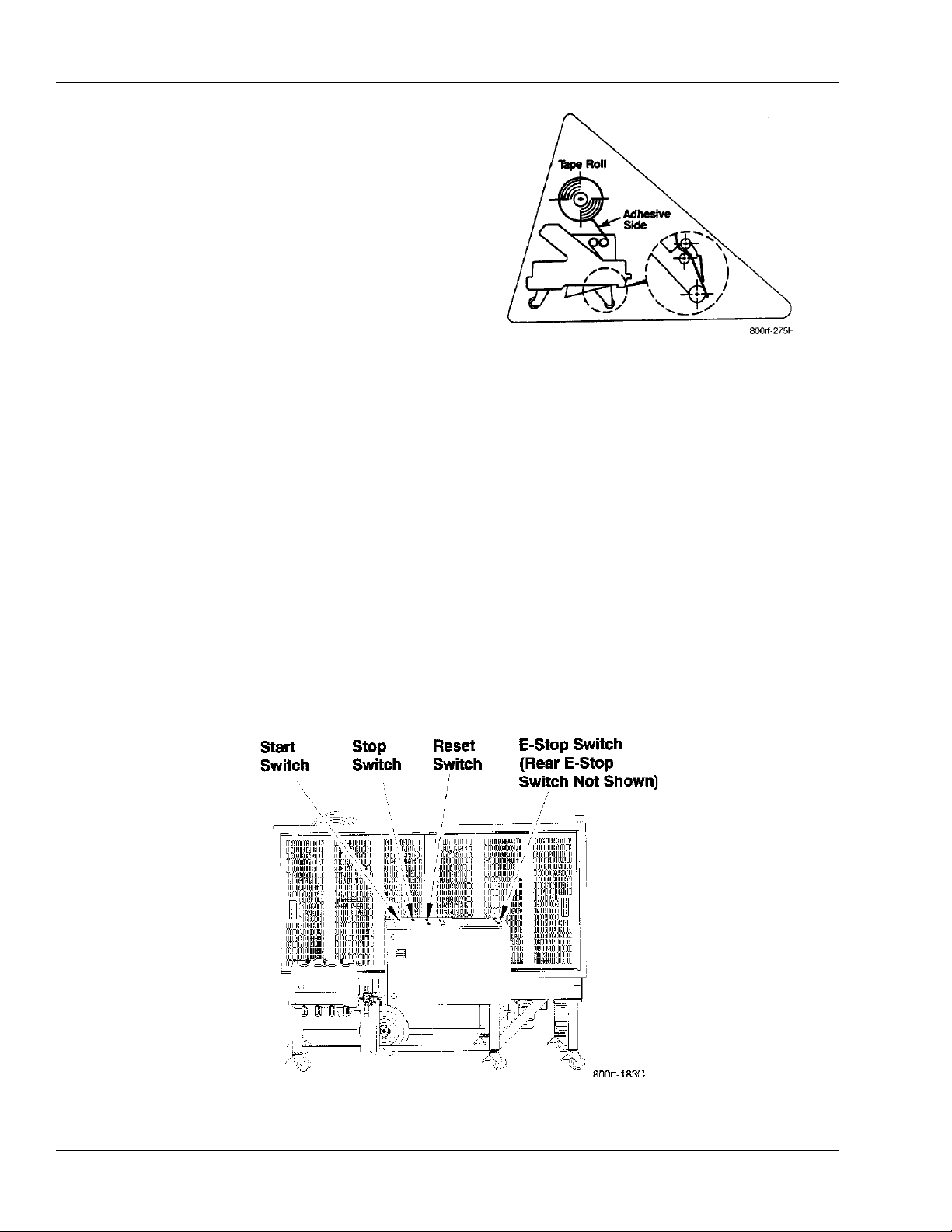
Tape Threading Label
The Tape Threading Label, shown in Figure 3, is
attached to the left side of both the upper and lower
taping heads. This label provides a convenient tape
threading diagram. More detailed tape loading and
threading information is provided in this manual in
Section 2, Installation.
Figure 3. Tape Threading Label
STOP Switches
The Model 800rf Type 39800 Case Sealer is
equipped with three STOP switches. Their locations
are shown in Figure 4. Pressing either of the red EStop switches stops the machine, removing electrical power and air pressure from the case sealer. To
restart the machine, you must turn and release the EStop switch and then press the RESET button and
the START button on the Electrical Control Panel.
Pressing the STOP button on the Electrical Control
Panel stops the machine and does not remove power
from the controller. To restart the machine, you must
press the RESET button and then the START button.
Figure 4. STOP Switch Locations
viii Copyright 1999, 3M IPC. All rights reserved.
Page 13

3M-Matic 800rf Case Sealer Warranty
Equipment Warranty and Limited Remedy: THE FOLLOWING WARRANTY IS MADE IN LIEU OF
ALL OTHER WARRANTIES, EXPRESS OR IMPLIED, INCLUDING, BUT NOT LIMITED TO, THE
IMPLIED WARRANTY OF MERCHANTABILITY, THE IMPLIED WARRANTY OF FITNESS FOR A
PARTICULAR PURPOSE AND ANY IMPLIED WARRANTY ARISING OUT OF A COURSE OF
DEALING, A CUSTOMER OR USAGE OF TRADE:
3M sells its 3M-Matic
1. The Taping Head knife blades, springs and rollers will be free from all defects for ninety (90) days after
delivery.
2. All other Taping Head parts will be free from all defects for three (3) years after delivery.
3. All other parts will be free from all defects for ninety (90) days after delivery.
If any part is proved to be defective within its warranty period, then the exclusive remedy and 3Ms and sellers
sole obligation shall be, at 3Ms option, to repair or replace the part, provided the defective part is returned
immediately to 3Ms factory or an authorized service station designated by 3M. A part will be presumed to have
become defective after its warranty period unless the part is received or 3M is notified of the problem no later
than five (5) calendar days after the warranty period. If 3M is unable to repair or replace the part within a
reasonable time, then 3M at its option, will replace the equipment or refund the purchase price. 3M shall have no
obligation to provide or pay for the labor required to install the repaired or replacement part. 3M shall have no
obligation to repair or replace: (1) those parts failing due to operation misuse, carelessness or due to any
accidental cause other than equipment failure, or (2) parts failing due to non-lubrication, inadequate cleaning,
improper operating environment, improper utilities or operator error.
Limitation of Liability: 3M and seller shall not be liable for direct, indirect, special, incidental or consequential
damages based upon breach of warranty, breach of contract, negligence, strict liability or any other legal theory.
The foregoing Equipment Warranty and Limitation of Liability may be changed only by a written agreement
signed by authorized officers of 3M and seller.
800rf Fully Automatic Random Case Sealer with the following warranties:
Copyright 1999, 3M IPC. All rights reserved. ix
Page 14

Warranty 3M-Matic 800rf Case Sealer
This page intentionally left blank.
x Copyright 1999, 3M IPC. All rights reserved.
Page 15

3M-Matic 800rf Case Sealer Description and Specifications
Table of Contents
1. Description and Specifications ..................................................................................................................... 1-1
1-1. Intended Use ............................................................................................................................................. 1-1
1-2. Description ............................................................................................................................................... 1-2
1-3. Specifications ........................................................................................................................................... 1-3
1-4. Case Sealing Rate Approximation Formula .............................................................................................1-4
1-5. Machine Dimensions ................................................................................................................................1-5
Copyright 1999, 3M IPC. All rights reserved. 1-i
Page 16

Description and Specifications 3M-Matic 800rf Case Sealer
This page intentionally left blank.
1-ii Copyright 1999, 3M IPC. All rights reserved.
Page 17
3M-Matic 800rf Case Sealer Description and Specifications
1. Description and Specifications
1-1. Intended Use
The 3M-Matic Model 800rf Type 39800 Automatic
Random Case Sealer with AccuGlide II Taping
Heads is designed to accept filled, regular slotted
containers from an existing conveyor, fold the top
flaps, and apply a C clip of Scotch brand Pressure-Sensitive Film Box Sealing Tape to the top and
bottom center seams. Two side-drive belt assemblies
convey the cases through the machine.
The 800rf Case Sealer is to be used with infeed and
exit conveyors supplied by the customer. Do not
attempt to run the case sealer without infeed and exit
conveyors in place.
ü Note
In this manual, the end of the case sealer that accepts cases
for taping is the infeed end. The end of the case sealer where
the taped cases leave is the exit end. The side containing the
Electrical Control Panel and the Pneumatic Control Panel is
the front or left side of the machine, and the opposite side is
the back or right side of the machine.
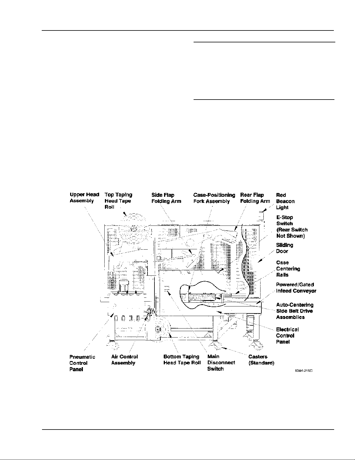
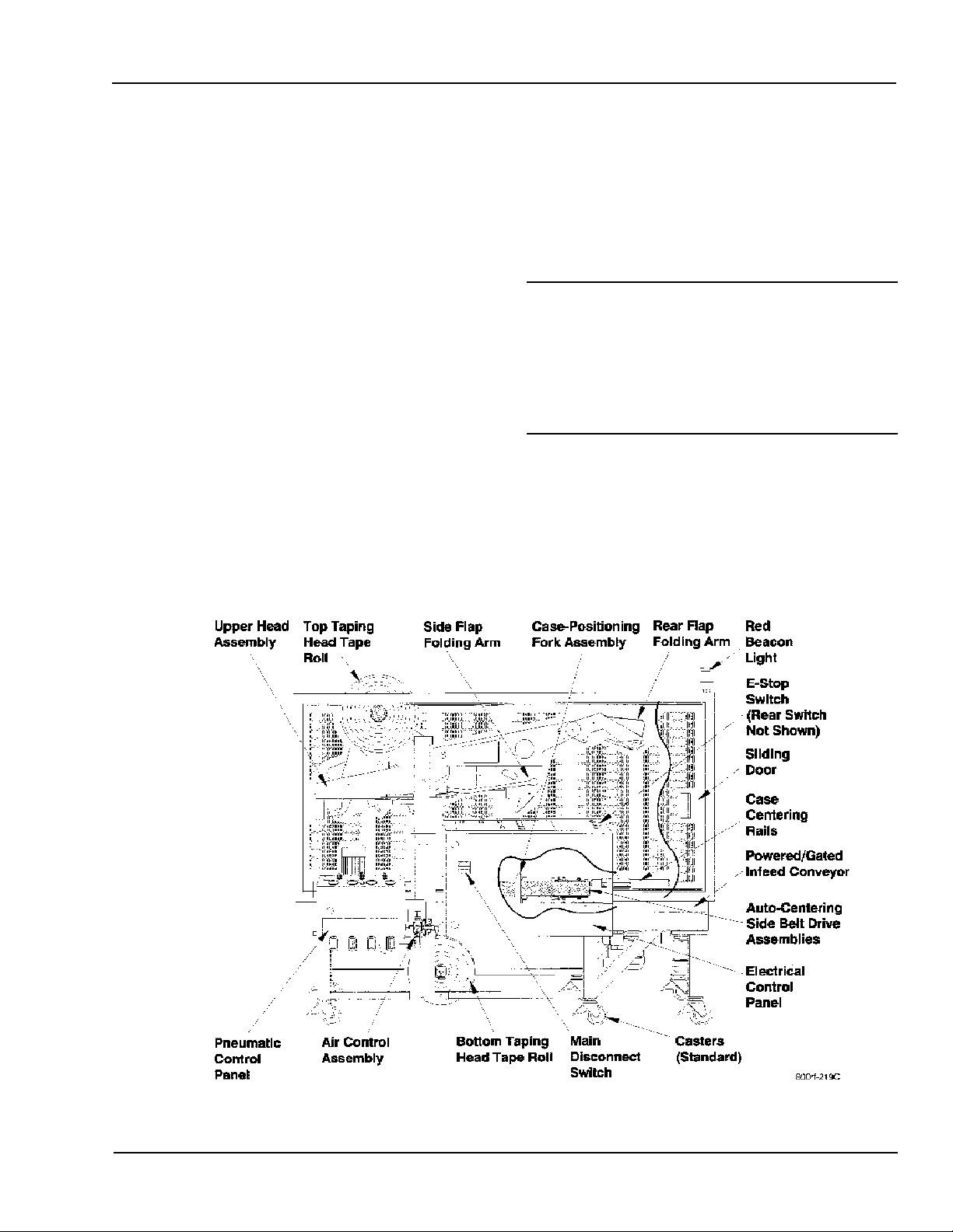
Figure 1-1 shows the 800rf Case Sealer with callouts
to identify its major components.
Figure 1-1. 3M-Matic 800rf Case Sealer
3M-Matic, AccuGlide, and Scotch are trademarks of 3M, St. Paul, MN 55144-1000
Copyright 1999, 3M IPC. All rights reserved. 1-1
Page 18
Description and Specifications 3M-Matic 800rf Case Sealer
1-2. Description
The 800rf Case Sealer is controlled from two operator
control panels located on the front left side of the case
sealer. These control panels (Electrical Control Panel
and Pneumatic Control Panel) have the most-used
controls within easy reach of the operator. The case
sealer is microprocessor-based and firmware controlled to maintain maximum and precise control over
all operations within the case sealer.
The case sealer may be operated in Random, Fixed, or
Bypass mode. A selector switch is located on the top
of the Electrical Control Panel.
!
Caution
Never change operating modes while a box is
in the case sealer. Change modes only after a
box exits the case sealer and before the next
box enters the case sealer.
• In Random mode, the case sealer automatically
adjusts itself for a wide range of case sizes,
providing a tape seal on the top and bottom of the
cartons. Random mode is considered the standard
operating mode.
• In Fixed mode, the case sealer runs multiple
cartons of the same (fixed) size, providing a tape
seal on the top and bottom of the cartons.
• In Bypass mode, the case sealer passes certain
containers through the machine, providing a tape
seal only on the bottom of the containers. The top
of these containers is not sealed.
1-2 Copyright 1999, 3M IPC. All rights reserved.
Page 19

3M-Matic 800rf Case Sealer Description and Specifications
1-1. Specifications
Tape:
3M brand pressure-sensitive film box sealing tapes.
Tape Width:
Standard 3M-Matic 800rf Case Sealer.
This model offers tape widths from 1-1/2 inches
[36 millimeters] minimum to 2 inches [48
millimeters] maximum.
3M-Matic 800rf-3 Case Sealer.
This model offers 3-inch wide upper and lower
AccuGlide II Taping Heads for tape widths
from 2 inches [48 millimeters] to
3 inches [72 millimeters].
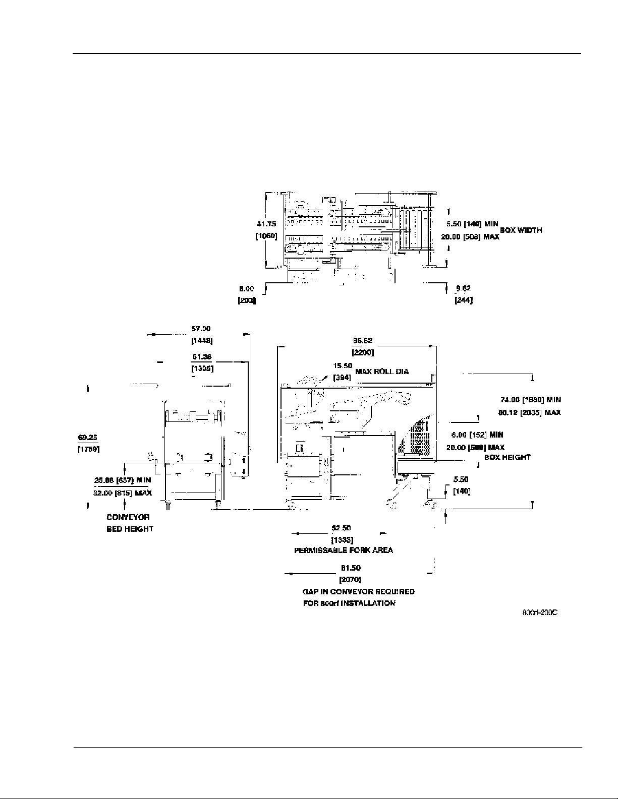
Tape Roll Diameter:
Up to 15-1/2 inches [394 millimeters] maximum, on
a 3-inch [76.2 millimeters] diameter core.
Box Dimensions:
Length: 8 inches [203 millimeters] minimum,
24 inches [610 millimeters] maximum.
Width: 5-1/2 inches [140 millimeters] minimum,
20 inches [508 millimeters] maximum.
Height: 6 inches [152 millimeters] minimum,
20 inches [508 millimeters] maximum.
Box Weight Capacity: (filled)
65 pounds [29 kilograms] maximum; minimum must
be sufficient to hold case on the conveyor bed with
bottom flaps flat.
Box Type:
Box board, 125 to 275 PSI bursting test, single wall
A, B, or C flute.
ü Note
The case sealer accommodates most boxes within the
size range identified above. However, if the ratio of
box length (in the taping direction) to box height is
0.6 or less, several boxes should be test-run to ensure
proper machine performance.
Operating Conditions:
o
Use in dry, relatively clean environments at 40
o
120
F [5oC to 49oC] with clean, dry boxes. The
F to
machine should not be washed down or subjected to
conditions causing moisture condensation on components.
Machine Specifications:
Length: 86-3/4 inches [2.20 meters].
Width: 57 inches [1.45 meters].
Height: 74 inches [1.88 meters] minimum
with casters to 80 inches [2.03 meters]
maximum with casters.
Weight: Unit uncrated, approximately
1130 pounds [513 kilograms].
Unit crated, approximately
1200 pounds [544 kilograms].
Case sealer bed height: Adjustable up from
factory-set height of 25-7/8 inches
[657 millimeters] to 32 inches
[815 millimeters] with casters.
Power Requirements:
Electrical: 208 to 240 VAC, 50/60 Hz, 5.5 Amps,
3-phase.
Pneumatic: Machine requires 75 140 PSIG
[5.2 9.5 BAR] 7.0 SCFM
3
[11.89 m
/h 21oC, 101 kPa] at the
regulator, maximum at maximum
cycle rate.
The optimum operating set point on
the gauge is 95 100 PSIG.
Infeed Conveyor Speed:
The customers infeed conveyor box delivery
speed must not exceed 60 feet/minute.
!
Caution
Do not connect a lubricator or lubricated
air to this machine. This machine has a
non-lubricated air circuit.
DETERMINE THE BOX LIMITATIONS BY
COMPLETING THIS FORMULA:
Box (tape) Length
> 0.6
Box Height
Copyright 1999, 3M IPC. All rights reserved. 1-3
Page 20
Description and Specifications 3M-Matic 800rf Case Sealer
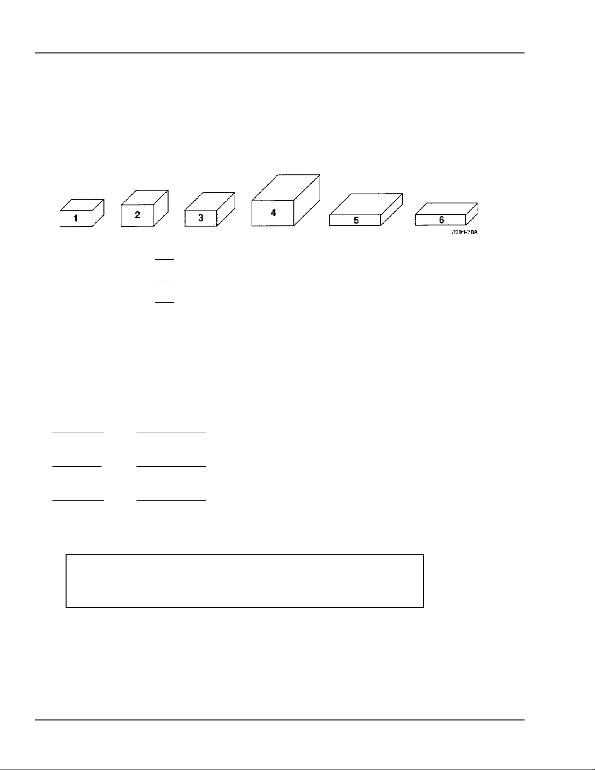
1-1. Case Sealing Rate Approximation Formula
To determine the case sealing rate for your application:
1. Obtain a representative sample of boxes in the proportion that will be run through the machine. Use as many
boxes as necessary to get an accurate sample.
Example:
1. Determine (add up) the
2. Determine (add up) the
3. Determine (add up) the
Number of boxes: _____________
Total length (inches): _____________
Total width (inches): _____________
Total height (inches): _____________
4. Divide the dimension totals by the number of boxes to determine average length, width, and height.
Total length _____________ = ____________ Average length
Number of boxes
Total width _____________ = ____________ Average width
Number of boxes
Total height _____________ = ____________ Average height
Number of boxes
total length of all boxes.
total width of all boxes.
total height of all boxes.
800rf Case Sealing Rate (cases per minute)
Rate = 5.97 + (0.42 X ave. length) (1.06 X ave. width) + (0.72 X ave. height)
1-4 Copyright 1999, 3M IPC. All rights reserved.
Page 21
3M-Matic 800rf Case Sealer Description and Specifications
1-1. Machine Dimensions
Figure 1-2 shows machine dimensions for the 800rf
Case Sealer. The dimensions are given in both inches
and millimeters. For example, 20.00 inches [508
millimeters] is shown as 20.00 [508].
Figure 1-2. Machine Dimensions
Copyright 1999, 3M IPC. All rights reserved. 1-5
Page 22

Description and Specifications 3M-Matic 800rf Case Sealer
This page intentionally left blank.
1-6 Copyright 1999, 3M IPC. All rights reserved.
Page 23

3M-Matic 800rf Case Sealer Installation
Table of Contents
2. Installation .....................................................................................................................................................2-1
2-1. General ............................................................................................................................................... 2-1
2-2. Unpacking ..........................................................................................................................................2-2
2-3. Setup Procedure ................................................................................................................................. 2-3
2-3-1. Case Sealer Bed Height ........................................................................................................ 2-3
2-3-2. Rear Emergency Stop Switch Installation ............................................................................ 2-3
2-3-3. Warning Beacon Installation ................................................................................................. 2-4
2-3-4. Pneumatic Connection .......................................................................................................... 2-4
2-3-5. Air Pressure Indicator ........................................................................................................... 2-5
2-3-6. Air Pressure Regulators ........................................................................................................ 2-5
2-3-7. Electrical Connection............................................................................................................ 2-6
2-4. Tape Loading ..................................................................................................................................... 2-8
2-4-1. Top Tape Head Loading ........................................................................................................ 2-9
2-4-2. Bottom Tape Head Loading ................................................................................................ 2-10
2-5. Tape Drum Friction Brake ............................................................................................................... 2-11
2-6. Checkout Inspection (to be performed by an authorized 3M Service Technician) .......................... 2-11
2-6-1. Static Tests .......................................................................................................................... 2-11
2-6-2. Programmable Controller Inputs and Outputs .................................................................... 2-12
2-6-3. Dynamic Tests ..................................................................................................................... 2-12
2-7. Placing 800rf Case Sealer in Production Line .................................................................................2-12
2-8. Special Setup Procedure .................................................................................................................. 2-12
2-8-1. Relocating Pneumatic and Electrical Control Panels ......................................................... 2-12
Copyright 1999, 3M IPC. All rights reserved. 2-i
Page 24

Installation 3M-Matic 800rf Case Sealer
This page intentionally left blank.
2-ii Copyright 1999, 3M IPC. All rights reserved.
Page 25
3M-Matic 800rf Case Sealer Installation
2-1. General
The following instructions are presented in the order
recommended for installing and setting up the 800rf
Case Sealer, as well as for learning the operating
functions and adjustments. Following these instructions step-by-step results in a thorough understanding of the case sealer and its installation in a production line that best uses the many features of the case
sealer. Refer to Figure 2-1 for nomenclature.
Uncrating and setting up the case sealer consists of
four steps:
1. Uncrating the equipment.
2. Assembling the case sealer as described in this
section.
3. Providing the electrical and pneumatic connections.
4. Installation of the case sealer in a production line.
Once you decide on a schedule to accomplish these
steps, contact:
3M Packaging Systems Division
Customer Support Center
Phone 1-800-328-1390
A 3M technician will be sent to your site to perform a
final checkout inspection.
ü Note
We recommend that you do not operate the case
sealer in a production situation until the final check-
out inspection is complete. For the final checkout
inspection, have a sufficient supply of cases in
representative sizes and weights to check the case
sealer under normal operating conditions.
Figure 2-1. 3M-Matic 800rf Case Sealer
Copyright 1999, 3M IPC. All rights reserved. 2-1
Page 26

Installation 3M-Matic 800rf Case Sealer
2-2. Unpacking
ü Note
It is the responsibility of the customer to uncrate
the case sealer. Lifting equipment (forklift,
overhead crane, etc.) is necessary to lift the case
sealer from its pallet.
The case sealer is delivered in one crate.
Perform the following inspection upon receipt of the
case sealer.
1. Inspect the shipping crate for damage that could
indicate internal damage to the case sealer.
Report any damage, missing parts, or other
problems to:
3M Packaging Systems Division
Customer Support Center
Phone 1-800-328-1390
2. Dismantle the crate.
3. Inspect the case sealer and uninstalled components for damage or missing parts. The crate
should also contain the following:
• One tool box containing:
1 wrench, tube, 17 mm
1 wrench, box/open, 13 mm & 10 mm
1 wrench, box/open, 8 mm & 7 mm
1 wrench, open end, 25 mm
1 wrench, hex key, 3 mm
1 wrench, hex key, 4 mm
1 wrench, hex key, 5 mm
1 wrench, hex key, 6 mm
1 spring, main upper (78-8070-1274-1)
1 spring, main lower (78-8070-1273-3)
4 springs, cutter (78-8052-6602-6)
2 blades, cutter (78-8017-9173-8)
1 tool, tape threading (78-8076-4726-4)
4. Report any damage, missing parts, or other
problems to:
3M Packaging Systems Division
Customer Support Center
Phone 1-800-328-1390
5. Move the case sealer to the point of use, but do
not place it into production until after the 3M
technician completes the checkout inspection.
• One latching emergency stop switch with bracket
(electrically connected, but not mounted in place)
• One warning beacon with bracket (electrically
connected, but not mounted in place)
2-2 Copyright 1999, 3M IPC. All rights reserved.
Page 27
3M-Matic 800rf Case Sealer Installation
2-3. Setup Procedure
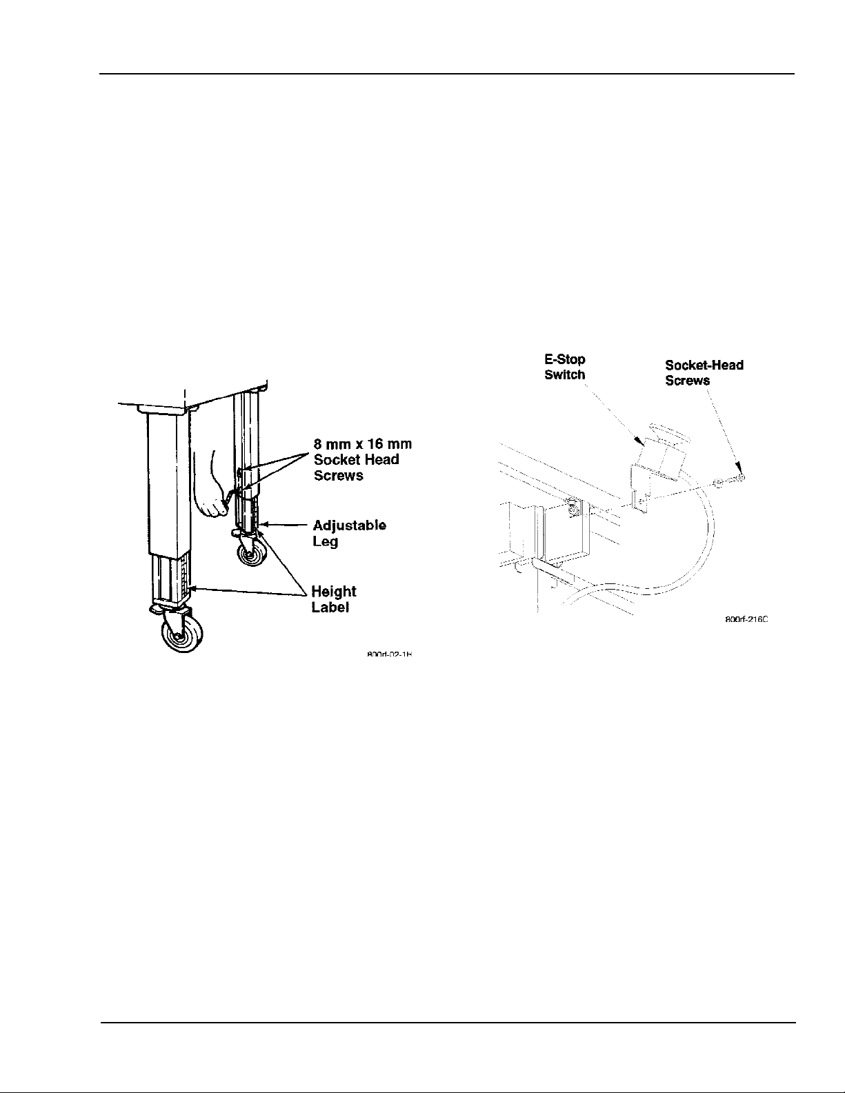
2-3-1. Case Sealer Bed Height
The legs on the case sealer can be adjusted to obtain
different bed heights from the factory set-point. The
bed height can be set from 25-7/8 inches [657 mm]
minimum through 32 inches [815 mm] maximum. Set
the bed height as follows:
1. Block up the case sealer frame to allow adequate
leg adjustment.
2. Using a 6 mm hex key wrench, loosen, but do not
remove, two M8 x 16 mm socket-head cap screws
in one leg. Refer to Figure 2-2.
2-3-2. Rear Emergency Stop Switch
Installation
A latching Emergency Stop (E-Stop) switch is
electrically connected to the case sealer, but not
mounted to the machine. Install this E-Stop switch on
the rear side of the case sealer.
1. Remove the protective wrap from the E-Stop
switch and bracket assembly.
2. Secure the E-Stop switch bracket to the rear
sliding door support bracket with the socket-head
screw provided. Refer to Figure 2-3.
Figure 2-3. Rear E-Stop Switch Installation
Figure 2-2. Bed Height Adjustment
3. Using the height label as a guide, adjust the leg
length to the desired conveyor bed height. Retighten the two screws to secure the leg.
4. Adjust the five remaining legs in the same way.
Copyright 1999, 3M IPC. All rights reserved. 2-3
Page 28

Installation 3M-Matic 800rf Case Sealer
2-3-3. Warning Beacon Installation
A red warning beacon is electrically connected to the
case sealer, but not mounted to the machine. Install
this warning beacon on top of the frame support
member to which it is connected.
1. Remove the protective wrap from the warning
beacon and L-bracket assembly.
2. Remove the top hex-head screw from the frame
support member. Refer to Figure 2-4.
3. Secure the warning beacon L-bracket to the
frame support member with the screw just
removed.
2-3-4. Pneumatic Connection
The case sealer requires a compressed air supply of
75 140 PSIG [5.2 9.5BAR] 7.0 SCFM [11.89m
o
C, 101kPa] maximum at maximum cycle rate. The
21
optimum operating set-point on the gauge is 95 100
PSIG. As shown in Figure 2-5, an On/Off Valve, Main
Air Pressure Regulator, and Filter are provided to
service the air supply.
Connect the air supply line to the Main Air Pressure
Regulator On/Off Valve.
ü Note
The air supply On/Off Valve has provisions for
lockout/tagout according to plant regulations.
3
/h
Figure 2-4. Warning Beacon Installation
Figure 2-5. Air Supply Components
2-4 Copyright 1999, 3M IPC. All rights reserved.
Page 29
3M-Matic 800rf Case Sealer Installation
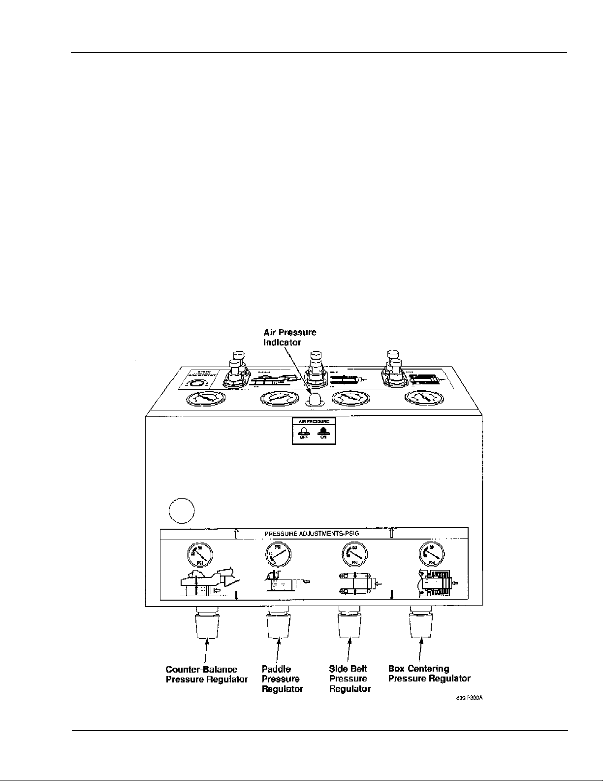
2-3-5. Air Pressure Indicator
The Pneumatic Control Panel (Figure 2-6) is
equipped with an Air Pressure Indicator to show, in
red, when the air circuit is energized. The Air
Pressure Indicator is located in the top center of
the control panel.
2-3-6. Air Pressure Regulators
There are four air pressure regulator control knobs
located on the underside of the Pneumatic Control
Panel. Their corresponding gauges are located across
the top of the Pneumatic Control Panel. Refer to
Figure 2-6.
Refer to the Adjustments section of this manual for
the recommended set points for each regulator
(Counter-Balance Pressure Regulator, Paddle Pressure Regulator, Side Belt Pressure Regulator, and
Box Centering Pressure Regulator). Also refer to the
label located on the lower front portion of the Pneumatic Control Panel.
To adjust any of these air pressure regulators, turn
its control knob clockwise (CW) to increase
pressure and counterclockwise (CCW) to decrease
pressure.
Figure 2-6. Pneumatic Control Panel
Copyright 1999, 3M IPC. All rights reserved. 2-5
Page 30

Installation 3M-Matic 800rf Case Sealer
2-3-7. Electrical Connection
!
Caution
Before making the electrical connection,
make sure that the red Latching Emergency
Stop switch located on the Electrical
Control Panel is depressed. Also ensure
that all packaging materials and tools are
removed from the case sealer.
The case sealer and its Electrical Control Panel are
wired for 208 240 VAC, 50/60 Hz, 3-phase power
and a power cord is connected. However, no power
plug is supplied. The power cord can be wired
directly into a power distribution box or a plug can be
installed. The recommended plug is a L15-20, 4-pin
twist-lock. Possible wire code combinations are:
Black Phase X or Black Phase X
White Phase Y Brown Phase Y
Red Phase Z Blue Phase Z
Green Ground Yel/Grn Ground
1. Turn the electrical power on by rotating the Main
Disconnect switch CW. Refer to
Figure 2-8. The white POWER indicator lights to
show that power is available. Refer to
Figure 2-7.
2. The red lights on the Electrical Control Panel
indicate a Fault/E-Stop switch condition. Turn
the red latching E-Stop switch CW to release
the switch. The red FAULT and E-STOP/
SLIDING DOOR indicators should turn off.
3. Press the blue RESET button on the Electrical
Control Panel. You should observe air-powered
movement of the Upper Head Assembly and the
Rear Flap Folding Arm, which moves to an
upright (extended) position.
4. Press the green START button on the Electrical
Control Panel. Pressing this button applies
electrical power to the two side belt drive motors
and the infeed roller drive motors. The RUN
indicator should light.
Viewing the case sealer from its infeed end, you
should observe the right/rear drive belt turning in
a CW direction and the left/front drive belt
turning in a CCW direction. With the belts
rotating as described, they will draw a carton
into the machine. This is the normal operating
condition.
ü Note
If the drive belts rotate in reverse, interchange any
two of the black, white, or red 208 220 VAC
wires at the plug or power distribution box. This
will restore the motors to the correct rotation.
2-6 Copyright 1999, 3M IPC. All rights reserved.
Page 31

3M-Matic 800rf Case Sealer Installation
Figure 2-7. Electrical Control Panel
(Top View)
Figure 2-8. Electrical Control Panel
(Front View)
Copyright 1999, 3M IPC. All rights reserved. 2-7
Page 32

Installation 3M-Matic 800rf Case Sealer
2-4. Tape Loading
Warning!
Turn air and electrical supplies off and
disconnect before servicing taping heads.
Never attempt to work on the taping heads
or load tape when the box drive system is
running. Each taping head is equipped
with an extremely sharp cut-off knife.
Before working with the taping heads or
attempting to load/thread tape, identify the
knife locations. Keep hands out of these
areas except as necessary to service the
taping heads. Failure to comply with these
warnings can result in severe personal
injury and/or equipment damage.
Figure 2-9 shows the components of the top taping
head.
The taping heads are pre-set to accommodate 2-inch
[48 mm] wide tape rolls. To use and apply 1-1/2 inch
[36 mm] or 1-3/4 inch [42 mm] wide tapes, refer to
the Adjustments section for set up information.
A tape-threading tool is shipped with the case sealer
for tape loading convenience. Retain the tool for
continued use in the tape loading operation. For
operator assistance, a threading diagram is applied to
the taping heads. However, it is recommended that
the more detailed instructions and illustrations in this
manual be referred to the first few times the tape is
loaded until the operator becomes thoroughly familiar
with the tape loading operation.
For convenience in loading, the bottom taping head
can be removed by lifting it out of the bed of the case
sealer. The upper head assembly must be in its
uppermost position to load tape in the top tape head.
Figure 2-9. Top Taping Head Components
2-8 Copyright 1999, 3M IPC. All rights reserved.
Page 33

3M-Matic 800rf Case Sealer Installation
2-4-1. Top Tape Head Loading
1. Turn off the Main Disconnect Switch on the
Electrical Control Panel.
2. Insert the tape-threading tool downward around
the rollers, as shown in Figure 2-10.
Figure 2-11. Attach Tape to Threading Tool
Figure 2-10. Insert Tape Threading Tool
3. Place the tape roll on the drum to dispense tape
from the bottom of the roll toward the infeed end
of the machine with the tape adhesive-side up.
Attach the tape leading end to the upper end of
the tape-threading tool, as shown in
Figure 2-11.
4. Manually turn the tape roll to create slack tape
while pulling the tape-threading tool through the
tape-applying mechanism until the tool is in
alignment with the applying roller.
5. Cut off the excess tape with a scissors or knife
below the applying roller. Refer to Figure 2-12.
Retain the tape-threading tool for future use.
Figure 2-12. Cut Off Tape
Copyright 1999, 3M IPC. All rights reserved. 2-9
Page 34

Installation 3M-Matic 800rf Case Sealer
2-4-2. Bottom Tape Head Loading
The bottom taping head is loaded and threaded in the
same manner as the top taping head. For ease in
loading, lift the bottom taping head from the conveyor bed and follow the top tape head loading
procedure. Refer to Figure 2-13.
Figure 2-13. Bottom Taping Head
2-10 Copyright 1999, 3M IPC. All rights reserved.
Page 35

3M-Matic 800rf Case Sealer Installation
2-5. Tape Drum Friction Brake
1. Refer to Figure 2-14. Turn the locking nut
clockwise to increase the braking force or counterclockwise to decrease the force.
2. Adjust the friction brake for the minimum
braking force that prevents excessive overtravel.
ü Note
Excessive braking force causes poor tape application
and may lead to tape tabbing on the trailing tape leg.
2-6. Checkout Inspection
(to be performed by an authorized
3M Service Technician)
2-6-2. Static Tests
1. Connect the air supply line and the electrical
power to the case sealer and power up the machine.
a. Turn the Air On/Off Valve to the ON posi-
tion.
b. Turn the Main Disconnect Switch on the
Electrical Control Panel to the ON position.
c. Press the RESET button on the Electrical
Control Panel.
2. Verify the following conditions:
• Air Pressure Indicator on the Pneumatic
Control Panel is red, showing that air pressure
is applied to the system, the rear flap folding
arm is extended, and the flap folder is retracted.
Figure 2-14. Friction Brake Adjustment
• Paddle is down.
• Side belts are out.
• Box centering rails are out.
• Box stop gate is up.
3. Check the Main Input Air Pressure Regulator.
The pressure gauge should read 95 PSIG.
a. If the pressure is lower, check the input
pressure at the source. If the pressure is lower
than 75 PSIG, there is not enough pressure to
operate the case sealer properly.
b. If the pressure is above 95 PSIG, adjust the
air pressure regulator to read 95 PSIG on the
gauge. (CW increases pressure,
CCW decreases pressure).
Copyright 1999, 3M IPC. All rights reserved. 2-11
Page 36

Installation 3M-Matic 800rf Case Sealer
4. Check the Box Centering Pressure gauge on the
Pneumatic Control Panel. Refer to Figure 2-15.
The gauge should read 40 60 PSIG. If the
pressure does not fall within this range, adjust the
pressure regulator (CW increases pressure,
CCW decreases pressure).
5. Check the Side Belt Pressure gauge on the
Pneumatic Control Panel. The gauge should read
40 60 PSIG. If necessary, adjust the Side Belt
Pressure Regulator to this setting. (CW increases pressure, CCW decreases pressure).
6. Check the Paddle Pressure gauge on the Pneumatic Control Panel. The gauge needle should be
at 7 PSIG. Adjust as needed.
7. Check the Counter-Balance Pressure gauge on the
Pneumatic Control Panel. The gauge should read
40 60 PSIG. If the pressure does not fall within
this range, adjust the pressure regulator (CW
increases pressure, CCW decreases pressure).
Figure 2-15. Pneumatic Control Panel
2-12 Copyright 1999, 3M IPC. All rights reserved.
Page 37

3M-Matic 800rf Case Sealer Installation
8. Press the START button on the Electrical Control
Panel. Refer to Figure 2-16. Verify that the side
belts and the infeed rollers start turning.
ü Note
If pressing the START button does not result in
continuous running of the side belt drive motors and
the infeed drive motors, then a Fault Condition
exists. Check the motor overload circuit breakers
OL1, OL2, OL3, and OL4, which are the most likely
cause. These circuit breakers are located inside the
Electrical Control Panel. Make sure the green
START buttons are all pushed in.
Figure 2-16. Electrical Control Panel
9. Check the operation of the red latching
Emergency Stop switches (one E-Stop switch is
located on the Electrical Control Panel and the
other switch is located at the rear of the machine)
and the STOP button on the Electrical Control
Panel. Verify that the drive motors stop when
either E-Stop switch is pressed or the STOP
button is pressed.
The case sealer must be restarted each time it
stops before checking the next switch. Restart the
machine by pressing the RESET button and then
the START button.
Caution
!
If the EMERGENCY STOP switches or the
STOP button do not function properly, do
not continue with the checkout. Refer to the
Theory of Operation and Troubleshooting
sections and correct the situation before
continuing.
Warning!
Steps 10 and 11 require opening the
Electrical Control Panel door. This exposes
220 VAC. Be cautious or personal injury
can result.
Copyright 1999, 3M IPC. All rights reserved. 2-13
Page 38

Installation 3M-Matic 800rf Case Sealer
10. Check the operation of the electrical interlocks
for the sliding doors. With the drive motors
running, move each sliding door, one at a time,
from its closed position. Verify that the drive
motors stop and that they cannot be restarted by
pressing the RESET button and then the START
button until the door is closed.
Verify also that when the door is open only
OUTPUT LEDs 13 and 14 are ON and no INPUT
LEDs are displayed on the Programmable Controller located inside of the Electrical Control
Panel.
11. Refer to Figure 2-17. Check the operation of the
photocells PC1 through PC6. Cover each photocell in turn and observe the associated INPUT
LED number displayed on the Programmable
Controller. The INPUT LED should be ON when
the associated photocell is covered.
Photocell INPUT LED
PC1 IN 4
PC2 IN 5
PC3 IN 6
PC4 IN 7
PC5 IN 8
PC6 IN 9
Figure 2-17. Photocell Locations
2-14 Copyright 1999, 3M IPC. All rights reserved.
Page 39

3M-Matic 800rf Case Sealer Installation
2-6-2. Programmable Controller Inputs and
Outputs
Figure 2-18 shows the SLC 500 Programmable
Controller used in the 3M-Matic 800rf Type 39800
Case Sealer. The Programmable Controller is located
inside of the Electrical Control Panel.
Figure 2-18. SLC 500 Programmable Controller
Copyright 1999, 3M IPC. All rights reserved. 2-15
Page 40

Installation 3M-Matic 800rf Case Sealer
Figure 2-19 shows the Programmable Controller
lights that turn on during the following startup
conditions.
POWER ON RESET START
POWER POWER POWER
PC RUN PC RUN PC RUN
INPUT 3 INPUT 0, 3, 11, 15 INPUT 0, 3, 11, 15
OUTPUT 1, 3 , 7, 12, 15
Figure 2-19. Programmable Controller Startup Conditions
2-16 Copyright 1999, 3M IPC. All rights reserved.
Page 41

3M-Matic 800rf Case Sealer Installation
Table 2-1 lists the INPUT LEDs displayed on the
Programmable Controller, the names of the input
signals that feed the LEDs, and the conditions that
cause the LEDs to turn ON or OFF.
View the LEDs with the Main Disconnect Switch and
the Air On/Off Valve turned to their ON positions.
Table 2-1. Programmable Controller Inputs
INPUT LED Input Signal Name LED Condition
0 Stop OFF when STOP button is pushed.
1 Start ON when START button is pushed.
2 Reset ON when RESET button is pushed.
3 E-Stop/Sliding Door OFF when E-Stop switch is pushed or door is opened.
4 PC1 ON when photocell PC1 is blocked.
5 PC2 ON when photocell PC2 is blocked.
6 PC3 ON when photocell PC3 is blocked.
7 PC4 ON when photocell PC4 is blocked.
8 PC5 ON when photocell PC5 is blocked.
9 PC6 ON when photocell PC6 is blocked.
10 Box Height (Paddle) Switch ON when paddle is pushed up.
11 Head Upper Limit Switch ON when upper head assembly is at its upper limit.
12 Minimum Width Switch ON when side belt assemblies close to innermost position.
13 Fixed Mode Switch ON when selector switch is set to FIXED position.
14 Bypass Mode Switch ON when selector switch is set to BYPASS position.
15 Low Air Pressure Switch ON when air pressure is above 50 PSIG.
16 Flap Folder Arm Switch ON when cylinder piston is near reed switch.
17 Overload ON when any motor overload switch trips.
18 Not used
19 Not used
20 Not used
21 Not used
22 Not used
23 Not used
Copyright 1999, 3M IPC. All rights reserved. 2-17
Page 42

Installation 3M-Matic 800rf Case Sealer
Table 2-2 lists the OUTPUT LEDs displayed on the
Programmable Controller, the names of the output
signals that feed the LEDs, and the conditions that
cause the LEDs to turn ON or OFF.
View the LEDs with the Main Disconnect Switch and
the Air On/Off Valve turned to their ON positions.
Table 2-2. Programmable Controller Outputs
OUTPUT LED Output Signal Name LED Condition
0 Side Belt Lock ON when side belts lock.
1 Side Drive Motors ON when side belt drive motors are running.
2 Flap Folder Arm ON when flap folder arm is down.
3 Infeed Gate ON when infeed gate is down.
4 Centering Rails ON when photocell PC1 is blocked.
5 Side Drive Assembly Closing ON when photocell PC3 is blocked.
6 Paddle Cylinder ON when paddle is pushed up.
7 Fork Cylinder ON when fork is up.
8 Head Assembly Cylinder Brakes ON when brakes turn on.
9 Head Raising Cylinder Lower Port ON when upper head assembly lowers.
10 Head Raising Cylinder Upper Port ON when upper head assembly raises.
11 Rear Flap Folder ON when rear flap folder folds last minor flap.
12 Infeed Motors (2) ON when infeed motors are running.
13 Alarm ON when any fault condition exists.
14 E-Stop Signal ON when either E-Stop switch is pushed.
15 Ready Signal ON when START button is pushed.
2-18 Copyright 1999, 3M IPC. All rights reserved.
Page 43

3M-Matic 800rf Case Sealer Installation
2-6-3. Dynamic Tests
The following procedures check the actual operation
of the 800rf Case Sealer. The following conditions
must be observed.
• Electrical power and compressed air are available
and turned on.
• The four safety doors are in their closed posi-
tions.
• Cases should have:
− the bottoms folded closed
− a minimum weight to hold the case on the
conveyor bed with the bottom flaps flat
− the front and rear flaps inside the side flaps
1. Apply air pressure and electrical power and press
the RESET and the START buttons on the
Electrical Control Panel.
2. If applicable, run the longest box (19 inches to 24
inches) through the case sealer. Check the
following sequence of events.
a. The box feeds from the infeed conveyor
rollers. The box is centered by the box
centering rails and the box stop gate moves
up.
f. The side belts restart.
g. Just before the sides of the box are folded
down, the rear flap of the box is folded down
into place.
ü Note
The timing of step g will vary depending on the
length of the box.
h. The sides of the box are folded down.
i. The top flap compression rollers touch the
sides of the top of the box without causing
the side flaps to overlap.
j. C-clips of tape are applied to both the top and
bottom center seams of the box.
k. The box exits the case sealer.
l. The head rises to its upper position, the side
belts return to their outer position, the fork
rises to its normal position, and the box stop
gate lowers to allow the next box to be fed
into the machine.
ü Note
If any of the steps outlined above do not occur
correctly, refer to the appropriate adjustment in the
Adjustments section of this manual.
b. The box is released and moves to the side
belts.
c. The side belts move inward and hold the box,
driving it toward the fork.
d. The box arrives at the fork and the side belts
stop driving the box.
e. The head lowers to the box, stopping at the
top of the box without distorting it.
3. If applicable, repeat the procedure outlined in
step 2 using the shortest box (8 inches to 13
inches).
4. If applicable, repeat the procedure outlined in
step 2 using a box between 12 and 19 inches.
5. Now that a representative sample of boxes has
been checked and appropriate adjustments have
been made, flood the infeed line with a random
array of boxes and check for consistent operation of the case sealer.
Copyright 1999, 3M IPC. All rights reserved. 2-19
Page 44

Installation 3M-Matic 800rf Case Sealer
2-7. Placing 800rf Case Sealer in
Production Line
When installing the 800rf Case Sealer into a production line, ensure compliance with the following
requirements:
• The case sealer must be level.
• The customers infeed conveyor may be powered
or inclined to the case sealer.
• The customers infeed conveyor box delivery
speed CANNOT exceed 60 ft/min.
• The customers exit conveyor may be powered or
inclined whichever positively conveys boxes
away from the exit end of the case sealer.
• The width of the customers infeed conveyor and
exit conveyor should fall within 22 inches [560
mm] minimum to 38 inches [965 mm] maximum.
Figure 2-20 shows the 800rf Case Sealer connected to
customer-supplied infeed and exit conveyors.
!
Caution
The 800rf Case Sealer must not be run in a
production line without being joined to the
customers infeed conveyor. This is to
restrict an operator from being exposed to
moving case sealer components during its
operation.
Figure 2-20. Typical Conveyor Setup
2-20 Copyright 1999, 3M IPC. All rights reserved.
Page 45

3M-Matic 800rf Case Sealer Installation
2-8. Special Setup Procedure
2-8-1. Relocating Pneumatic and Electrical
Control Panels
Warning!
Turn off electrical power and air supply and
disconnect power cord from electrical
supply before beginning this procedure.
Failure to comply with these warnings can
result in severe personal injury and/or
equipment damage.
Relocating the case sealer Pneumatic and Electrical
Control Panels from their standard position which is
the left/front side, as viewed from the infeed end of
the machine, enables the case sealer to be operated
from the right/rear side of the machine.
At various steps of this procedure it is recommended
that two (2) people be involved in moving certain
components from the front to the rear of the case
sealer.
ü Note
Following these procedures will accomplish having
the control panels located to the right/rear of the case
sealer and will orient the Electrical Control Panel on
the left and the Pneumatic Control Panel on the right,
as viewed by the operator facing the rear side of the
machine.
Removing Air On/Off Valve/Regulator/Filter,
Pneumatic Control Panel, and Brackets
1. Disconnect the air supply from the Air On/Off
Valve.
2. Open the Pneumatic Control Panel (use 8 mm hex
wrench) to assist in removing the input air line
from the air outlet on the Main Air Pressure
Regulator. Push in and hold the collet (release
ring) and pull the air line free. Refer to
Figure 2-21.
To prevent the case sealer from rolling, lock all the
casters before starting these procedures.
Figure 2-21. Disconnecting Air Line
Copyright 1999, 3M IPC. All rights reserved. 2-21
Page 46

Installation 3M-Matic 800rf Case Sealer
3. Disconnect the plastic conduit at the Electrical
Control Panel, which connects to the Pneumatic
Control Panel. This conduit contains the electrical wires for the valve solenoids.
4. Slide the left front sliding door all the way to the
right to provide additional access.
5. Remove the Air On/Off Valve/Regulator/Filter
bracket.
a. Remove the 2 socket-head screws (6 mm)
securing the bracket to the mainframe
bracket. Refer to Figure 2-22.
b. Set this bracket (with Air On/Off Valve/
Regulator/Filter attached) aside for use later.
6. Prepare two (2) blocks (10 long x 8 wide x 18
high). These blocks will be used to support the
control panels later in this procedure.
!
Caution
Blocks must be capable of supporting the
weight of the Electrical Control Panel, which
is about 50 pounds [22.7 kg].
7. Remove the Pneumatic Control Panel.
a. Place a block under the Pneumatic Control
Panel.
b. Remove the 4 socket-head screws (6 mm)
securing the control panel to the left and right
brackets. Refer to Figure 2-23.
c. Save these screws for use later.
d. Ease the control panel onto the block. Make
sure the block is centered under the control
panel so the panel is stable.
Figure 2-22. Removing Air On/Off Valve/
Regulator/Filter Bracket
Figure 2-23. Removing Pneumatic Control Panel
2-22 Copyright 1999, 3M IPC. All rights reserved.
Page 47

3M-Matic 800rf Case Sealer Installation
8. Remove the left and right mainframe brackets
that support the Pneumatic Control Panel. Refer
to Figure 2-24.
a. Remove 8 socket-head screws (6 mm)
securing the left support bracket to the case
sealer (4 screws holding the bracket to the
mainframe, and 4 screws holding the 2 L
brackets).
b. Remove 4 socket-head screws (6 mm)
securing the right support bracket to the case
sealer.
c. Save these screws and brackets for use later.
Moving Support Brackets and Installing Pneumatic Control Panel
9. Install the left support bracket and L brackets
(removed from the front of the machine) at the
rear of the machine. Refer to Figure 2-25. Secure
the brackets with the socket-head screws (6 mm).
10. Remove the right mainframe bracket from the
rear of the machine and install it at the front left
of the case sealer. Refer to Figure 2-25.
12. Install the Pneumatic Control Panel at the rear of
the case sealer.
a. Lift the Pneumatic Control Panel from the
block and slide it through the undercarriage
to the rear of the case sealer.
b. Block the control panel and then lift it and
carefully set it onto the support brackets.
c. Hold the control panel in place and secure it
to the support brackets with 4 socket-head
screws.
a. Remove the 6 socket-head screws (6 mm)
securing the mainframe bracket to the case
sealer (4 screws holding the bracket to the
mainframe, and 2 screws holding the bracket
to the underside of the door frame).
b. Install this bracket at the front left of the case
sealer. Secure the bracket to the mainframe
with 4 socket-head screws, and secure the
bracket to the underside of the door frame
with 2 socket-head screws.
11. Install the right support bracket (removed from
the front of the machine) at the rear right of the
case sealer. Refer to Figure 2-25. Secure the
bracket to the mainframe with 4 socket-head
screws.
Figure 2-24. Removing Support Brackets for
Pneumatic Control Panel
Copyright 1999, 3M IPC. All rights reserved. 2-23
Page 48

Installation 3M-Matic 800rf Case Sealer
Figure 2-25. Moving Support Brackets for Pneumatic Control Panel
2-24 Copyright 1999, 3M IPC. All rights reserved.
Page 49

3M-Matic 800rf Case Sealer Installation
Installing Air On/Off Valve/Regulator/Filter
13. Locate the Air On/Off Valve/Regulator/Filter and
bracket.
14. Rotate the bracket 180°.
a. Remove the lower socket-head screw (4
mm) and loosen the upper screw, but do not
remove it. Refer to Figure 2-26.
b. Punch a hole in the label. Then rotate the
bracket 180°. The label will be upside-down
(a replacement label is available and may
be ordered as replacement parts are ordered).
c. Secure the Air On/Off Valve/Regulator/
Filter to the bracket by installing the lower
socket-head screw and tightening the upper
screw. Refer to Figure 2-27.
15. Mount the bracket with the Air On/Off Valve/
Regulator/Filter to the left bracket that supports
the Pneumatic Control Panel.
Figure 2-26. Air On/Off Valve/Regulator/Filter
and Bracket
Figure 2-27. Air On/Off Valve/Regulator/Filter
and Bracket Rotated 180°
Copyright 1999, 3M IPC. All rights reserved. 2-25
Page 50

Installation 3M-Matic 800rf Case Sealer
16. Remove and separate the Air On/Off Valve
from the Regulator/Filter.
a. Loosen the hex screw in the bracket that
holds the two assemblies together. Refer to
Figure 2-28.
b. Separate the Air On/Off Valve from the
Regulator/Filter by removing both assemblies from the bracket.
17. Rotate the Regulator/Filter assembly 180°.
a. Swap the air gauge and air plug. Do this by
unscrewing the gauge and the plug, then
install the gauge in the hole previously
containing the plug, and vice versa.
b. Remove the air outlet and install it on the
opposite side of the regulator body.
c. Remove the filter bowl and shield by sliding
the lock down, rotating the unit in either
direction, and separating the unit from the
regulator body.
d. Install the filter bowl and shield so the lock
is located directly under the gauge.
18. Install the Air On/Off Valve and Regulator/
Filter so the air outlet on the Regulator/Filter is
facing the Pneumatic Control Panel and the Air
On/Off Valve is facing the Electrical Control
Panel. Refer to Figure 2-29.
a. Place the two assemblies in the bracket that
holds them together and tighten the hex
screw.
Figurer 2-28. Separate Air On/Off Valve from
Regulator/Filter
Figurer 2-29. Air On/Off Valve/Regulator/Filter
Reconfigured
2-26 Copyright 1999, 3M IPC. All rights reserved.
Page 51

3M-Matic 800rf Case Sealer Installation
19. Connect the air line from the Pneumatic Control
Panel to the air outlet on the regulator body.
a. Open the Pneumatic Control Panel (8 mm
hex wrench) and remove the center of the left
knockout grommet.
b. Locate the input air line, pull it out and loop
it around, then route it through the hole in
the left grommet (be careful not to kink the
air hose). Refer to Figure 2-30.
c. Connect the input air line to the air outlet by
inserting the air line fully into the collet and
pulling gently back to lock the air line into
place.
Figure 2-30. Rerouting Input Air Line
Copyright 1999, 3M IPC. All rights reserved. 2-27
Page 52

Installation 3M-Matic 800rf Case Sealer
Removing Electrical Control Panel
20. Remove the Electrical Control Panel. This step
requires two people.
a. Disconnect the large electrical connector and
the two smaller infeed motor electrical
connectors located under the Electrical
Control Panel.
b. Place two (2) blocks (described in Step 6)
under the Electrical Control Panel.
c. While holding the control panel firmly
against the support brackets, remove the 4
socket-head screws (6 mm) securing the
panel to the left and right brackets. Refer to
Figure 2-31.
d. Save these screws for use later.
e. Ease the control panel onto the blocks. Make
sure the blocks are centered under the control
panel so the panel is stable. Be careful not to
damage the electrical connectors.
f. Carefully move the blocked Electrical
Control Panel aside for later work.
Moving Support Brackets and Installing Electrical
Control Panel
21. Slide both sliding doors all the way to the exit
end of the machine to provide additional access.
22. Remove the right support bracket from the front
of the machine and install it at the rear right of
the case sealer.
a. Remove 6 socket-head screws (6 mm)
securing the right support bracket to the case
sealer (4 screws holding the bracket to the
mainframe, and 2 screws holding the bracket
to the two L brackets attached to the underside of the door frame). Refer to Figure 2-32.
b. Install this bracket at the rear right of the
case sealer. Refer to Figure 2-33. Secure the
bracket to the mainframe with 4 socket-head
screws.
Figure 2-32. Removing Support Brackets for
Electrical Control Panel
Figure 2-31. Removing Electrical Control Panel
2-28 Copyright 1999, 3M IPC. All rights reserved.
Page 53

3M-Matic 800rf Case Sealer Installation
Figure 2-33. Moving Support Brackets for Electrical Control Panel
23. Remove the mainframe bracket and E-Stop
switch from the rear left of the machine and
install the mainframe bracket at the front right of
the case sealer. Refer to Figure 2-33.
a. Remove 1 socket-head screw securing the
E-Stop switch and bracket to the mainframe
bracket. Set the E-Stop switch aside; it will
be installed later.
b. Remove 6 socket-head screws (6 mm)
securing the mainframe bracket to the case
sealer (4 screws holding the bracket to the
mainframe, and 2 screws holding the bracket
to the two L brackets attached to the underside of the door frame).
c. Install this bracket at the front right of the
case sealer. Secure the bracket to the mainframe and L brackets with 6 socket-head
screws.
24. Remove the left support bracket from the front
of the machine and install it at the rear left of the
case sealer. Refer to Figure 2-33.
a. Remove 4 socket-head screws (6 mm)
securing the left support bracket to the case
sealer.
b. Install this bracket at the rear left of the case
sealer. Secure the bracket to the mainframe
and L brackets with 6 socket-head screws.
25. Install the Electrical Control Panel at the rear of
the case sealer. This step requires two people.
a. With one person on each side, lift the
Electrical Control Panel from the blocks and
carefully set it onto the support brackets.
b. Hold the control panel in place and secure it
to the support brackets with 4 socket-head
screws.
Copyright 1999, 3M IPC. All rights reserved. 2-28
Page 54

Installation 3M-Matic 800rf Case Sealer
26. Connect the electrical connectors and cables to
the Electrical Control Panel.
a. Route the electrical connectors and cables
through the undercarriage to the rear of the
case sealer.
b. Connect the large electrical connector and
the two smaller infeed motor electrical
connectors to the receptacles located under
the Electrical Control Panel.
c. Connect the plastic conduit from the Pneu-
matic Control Panel to the receptacle located
under the Electrical Control Panel.
27. Install the E-Stop switch.
a. Locate the E-Stop switch and gently pull
sufficient wire (extra wire is coiled in the
frame) from the frame to route the E-Stop
switch under the machine to the front right
mainframe bracket.
b. Secure the E-Stop switch bracket to the
mainframe bracket with 1 socket-head screw.
Refer to Figure 2-34.
Verify Correct Operation
28. Close all four sliding doors to engage the
interlock switches.
29. Connect the main air supply to the Air On/Off
Valve.
30. Connect the power cord to the electrical supply.
31. Turn on the case sealer air supply and electrical
power.
32. Verify correct operation by running test cartons
through the case sealer.
Figure 2-34. Installing E-Stop Switch and Bracket
2-30 Copyright 1999, 3M IPC. All rights reserved.
Page 55

3M-Matic 800rf Case Sealer Adjustments
Table of Contents
3. Adjustments ...................................................................................................................................................3-1
3-1. Case Sealer Bed Height ..................................................................................................................... 3-1
3-2. Pneumatic Device Factory Set Points ................................................................................................3-2
3-3. Main Air Pressure Regulator ............................................................................................................. 3-4
3-4. Box Centering Pressure Regulator .....................................................................................................3-4
3-5. Side Belt Pressure Regulator ............................................................................................................. 3-5
3-6. Side Belts Closure Drive Chain .........................................................................................................3-5
3-7. Side Belts In/Out Rates ...................................................................................................................... 3-6
3-8. Side Belt Inner Limit ......................................................................................................................... 3-7
3-9. Side Belt Tension ...............................................................................................................................3-8
3-10. Motor Drive Belts, Upper and Lower ................................................................................................ 3-9
3-11. Drive Chain ...................................................................................................................................... 3-10
3-12. Safety Door Interlock....................................................................................................................... 3-10
3-13. Flap Folder Arm and Flap Folder Flow Controls - Speed Controls................................................. 3-11
3-14. Flap Folder Arm Reed Switch ......................................................................................................... 3-12
3-15. Cylinder Cushion Setting ................................................................................................................. 3-13
3-16. Paddle Pressure Regulator ............................................................................................................... 3-13
3-17. Counter-Balance Pressure Regulator ............................................................................................... 3-14
3-18. Case Top Sensitivity ........................................................................................................................3-14
3-19. Fork Cylinder Flow Controls - Speed Controls ............................................................................... 3-15
3-20. Infeed Box Stop-Gate Flow Control - Speed Control ...................................................................... 3-16
3-21. Box Centering Rails In/Out Rates ................................................................................................... 3-17
3-22. Upper Head Assembly Down/Up Rates........................................................................................... 3-18
3-23. Top Flap Compression Rollers ........................................................................................................ 3-19
3-24. Tape Web Alignment........................................................................................................................ 3-19
3-25. Tape Drum Friction Brake ............................................................................................................... 3-20
3-26. Tape Applying Mechanism Spring................................................................................................... 3-20
3-27. One-Way Tension Roller .................................................................................................................. 3-21
Copyright 1999, 3M IPC. All rights reserved. 3-i
Page 56

Adjustments 3M-Matic 800rf Case Sealer
3-28. Low Air Pressure Switch ................................................................................................................. 3-22
3-29. Overload Circuit Breaker ................................................................................................................. 3-23
3-30. Head Travel Limit Switch................................................................................................................ 3-23
3-ii Copyright 1999, 3M IPC. All rights reserved.
Page 57

3.
3M-Matic 800rf Case Sealer Adjustments
3. Adjustments
3-1. Case Sealer Bed Height
Specification
Adjust the case sealer bed height so that it is the same
height as the conveyor line to which it is attached.
Adjustment
1. Raise and support the case sealer frame to allow
adequate leg adjustment.
1. Using a 6 mm hex key wrench, loosen, but do not
remove, two M8 x 16 mm socket-head cap screws
in one leg. Refer to Figure 3-1.
Figure 3-1. Bed Height Adjustment
3. Using the height label as a guide, adjust the leg
length to the desired conveyor bed height.
Retighten the two screws to secure the leg.
4. Adjust the five remaining legs in the same way.
Copyright 1999, 3M IPC. All rights reserved. 3-1
Page 58

Adjustments 3M-Matic 800rf Case Sealer
3-2. Pneumatic Device Factory Set Points
Table 3-1 lists the factory set points for regulator pressure controls, Pneumatic Control Panel mounted speed
controls, and cylinder mounted speed controls. The table also describes the location of each adjustment.
Table 3-1. Pneumatic Device Factory Set Points and Adjustment Locations
Regulator Pressure Controls
Regulator Pressure Controls Set Value Adjustment Location
Main Input Air Pressure 95 PSIG Air On/Off Valve/Filter/Regulator and gauge
assembly
Box Centering Pressure 50 PSIG Regulator Underside of Pneumatic Control Panel,
extreme right
Side Belt Pressure 40 PSIG Regulator Underside of Pneumatic Control Panel,
second from extreme right
Paddle Pressure 7 PSIG Regulator Underside of Pneumatic Control Panel,
third from extreme right
Box Counter-Balance Pressure 40 PSIG Regulator Underside of Pneumatic Control Panel,
extreme left
To increase air pressure, turn the regulator knob clockwise (CW). To decrease air pressure, turn the regulator
knob counterclockwise (CCW). There is an air pressure gauge label located on the front of the Pneumatic
Control Panel referencing the gauges located on the top of the panel.
Pneumatic Control Panel Mounted Speed Controls
Air Rate Exhaust Restriction
Controls (Speed Controls) Set Value Adjustment Location
Centering Arms OUT 6 turns CCW Upper (OUT) of two restriction controls Top of
Pneumatic Control Panel, extreme right
Centering Arms IN 11 turns CCW Lower (IN) of two restriction controls Top of
Pneumatic Control Panel, extreme right
Side Belts OUT 9 turns CCW Upper (OUT) of two restriction controls Top of
Pneumatic Control Panel, center
Side Belts IN 6 turns CCW Lower (IN) of two restriction controls Top of
Pneumatic Control Panel, center
Head DOWN 11 turns CCW Lower (DOWN) of two restriction controls Top of
Pneumatic Control Panel, extreme left
Head UP 15 turns CCW Upper (UP) of two restriction controls Top of
Pneumatic Control Panel, extreme left
All adjustments are made from the fully closed position. Loosen the locking nut and turn the brass knurled
screw fully CW, then turn the screw CCW the number of turns specified above.
3-2 Copyright 1999, 3M IPC. All rights reserved.
Page 59

3M-Matic 800rf Case Sealer Adjustments
Table 3-1. Pneumatic Device Factory Set Points and Adjustment Locations (Continued)
Cylinder Mounted Speed Controls
Air Rate Exhaust Restriction
Controls (Speed Controls) Set Value Adjustment Location
Infeed Gate UP 3/4 of turn CCW On Gate Cylinder Underside of entrance end of
case sealer
Infeed Gate DOWN Not applicable No control device is present
Fork UP 12 turns CCW On Fork Cylinder cap end Remove center
conveyor bed to expose cylinder
Fork DOWN 13 turns CCW On Fork Cylinder rod end Remove center
conveyor bed to expose cylinder
Folder Arm EXTEND 11 turns CCW On Folder Arm Cylinder rod end Through access
holes in Arm Assembly cover
Folder Arm RETRACT 5 turns CCW On Folder Arm Cylinder cap end Through access
holes in Arm Assembly cover
Rear Flap Folder EXTEND 16 turns CCW On Rear Flap Folder Cylinder rod end Through
access holes in Folder Assembly cover
Rear Flap Folder RETRACT 10 turns CCW On Rear Flap Folder Cylinder cap end Through
access holes in Folder Assembly cover
All adjustments are made from the fully closed position. Use a standard straight edge screwdriver or loosen the
knurled ring nut and adjust the thumbscrew fully CW, then turn the thumbscrew CCW the number of turns
specified above.
Copyright 1999, 3M IPC. All rights reserved. 3-3
Page 60

Adjustments 3M-Matic 800rf Case Sealer
3-3. Main Air Pressure Regulator
Specification
The case sealer requires a compressed air supply of
75 140 PSIG [5.2 9.5 BAR] 7.0 SCFM
[11.89 m
cycle rate.
The optimum operating set point on the gauge is
95 100 PSIG.
Adjustment
If the pressure is lower than that specified, check the
input pressure at the source. If the source pressure is
lower than 75 PSIG [5.2 BAR], there is not enough
pressure to operate the case sealer properly. Also
note that the inner diameter and length of the
incoming air supply can affect final air pressure and
recovery rate SCFM.
If the pressure at the source is between 75 140
PSIG (this is the maximum pressure shown on the
gauge), make the following adjustment.
3
/h, 21oC, 101 kPa] maximum at maximum
ü Note
3-4 . Box Centering Pressure Regulator
Specification
The Box Centering Pressure Regulator should be
set to permit positive centering of the various
weights of boxes the customer is using. Set the
pressure to provide sufficient centering force
without creating excessive drag. Keep in mind the
maximum box weight capacity (filled) is 65 pounds,
and the minimum weight must be sufficient to hold
the case on the conveyor bed with the bottom flaps
flat.
Adjustment
1. Refer to Figure 3-3. Adjust the Box Centering
Pressure Regulator on the underside of the
Pneumatic Control Panel (CW increases
pressure, CCW decreases pressure). Observe
the Box Centering Pressure Gauge on the top of
the panel.
1. Refer to Figure 3-2. Adjust the Main Air Pressure
Regulator to read 95 100 PSIG on the gauge
(CW increases pressure, CCW decreases
pressure).
Figure 3-3. Box Centering Pressure Regulator
Adjustment
Figure 3-2. Main Air Pressure Regulator
Adjustment
3-4 Copyright 1999, 3M IPC. All rights reserved.
Page 61

3M-Matic 800rf Case Sealer Adjustments
3-5. Side Belt Pressure Regulator
Specification
The side belt pressure should be set so that cases are
driven smoothly through the sealing process by the
belts without the cases being deformed by excessive
side pressure.
!
Caution
Excessive belt wear occurs when side belts
are allowed to slip on the boxes.
Adjustment
1. Refer to Figure 3-4. Adjust the Side Belt
Pressure Regulator on the underside of the
Pneumatic Control Panel so that the gauge
reads 40 PSIG with the Main Air Pressure
Regulator set correctly (CW increases
pressure, CCW decreases pressure).
Observe the Side Belt Pressure Gauge on
the top of the panel.
ü Note
Air pressure can be reduced for light-weight cases.
Adjust side belt pressure so that the cases are centered and are driven smoothly.
3-6. Side Belts Closure Drive Chain
This is not a routine adjustment. Normally, it is
necessary only after major disassembly or repair of
related components.
Specification
Adjust the side belts closure drive chain so that the
side drive belts are equally spaced from the center of
the case sealer bed at their outermost position. The
tension of the drive chain must be tight enough to
ensure smooth inward drive.
Adjustment
1. Remove the case sealer bed plates as described in
Section 4-6, Case Sealer Bed Plates.
2. Refer to Figure 3-5. Loosen the lock nuts on the
drive chain.
3. Turn the adjustment bolts to obtain the proper
position and tension.
ü Note
If correct belt position cannot be obtained by means
of the adjustment bolts, remove the chain and
reposition it.
Figure 3-5. Side Belts Closure Drive Chain
Adjustment
4. Reinstall all parts removed in step 1.
Figure 3-4. Side Belt Pressure Regulator
Adjustment
Copyright 1999, 3M IPC. All rights reserved. 3-5
Page 62

Adjustments 3M-Matic 800rf Case Sealer
3-7. Side Belts In/Out Rates
This is not a routine adjustment. Normally, it is
necessary only after major disassembly or repair of
related components.
Specification
Adjust the Side Belt IN/OUT speed flow controls to
allow the side belts to move to the center of the case
sealer bed at approximately the same speed as they
return to their outer position. The rate of closure (IN)
is the primary measure of a good speed. It must be
slow enough to help center but not bounce a small
box, and not so slow as to reduce the overall production rate.
ü Note
If the side belts do not return (move OUT) from the
center of the case sealer bed when no box is present,
refer to Section 3-8, Side Belt Inner Limit, before
proceeding.
Adjustment
1. Pass an average size box through the case sealer.
2. Observe the rates of side belt closure and return.
3. Adjust the Side Belt IN/OUT speed control
valves, as shown in Figure 3-6 (CW decreases
speed, CCW increases speed). These controls
are located on the top of the Pneumatic Control
Panel.
ü Note
If there is any confusion as to where to set the speed
control valves, turn the valves fully CW and then
turn the OUT control 9 full turns CCW and turn the
IN control 6 full turns CCW. Refer to Table 3-1,
Pneumatic Device Factory Set Points and Adjustment Locations.
Figure 3-6. Side Belt IN/OUT Rate Adjustment
3-6 Copyright 1999, 3M IPC. All rights reserved.
Page 63

3M-Matic 800rf Case Sealer Adjustments
3-8. Side Belt Inner Limit
This is not a routine adjustment. Normally, it is
necessary only after major disassembly or repair of
related components.
Specification
With no box in the case sealer, adjust the side drive
belt assembly inner limit reed switch so that the
assembly closes to the center of the case sealer bed.
All side drive belt motors stop and the assembly
returns to its outermost position.
Adjustment
1. Raise the upper head assembly to its uppermost
position by setting the mode selector switch to
RANDOM and pressing the RESET button.
2. Turn off the main air valve and the electrical
disconnect switch.
3. Refer to Section 4-6, Case Sealer Bed Plates, and
remove the center roller assembly.
6. If the side drive belt assembly does not move to
its outermost position, press the STOP button.
The assembly will move out so the following
adjustment can be made.
7. Refer to Figure 3-7. Using a 2 mm hex wrench
loosen the screws on the reed switch. Move the
switch to the right in increments until, when
tested as described earlier, the assembly returns
to its outermost position.
8. Replace the center roller assembly.
4. Turn on the main air valve and the electrical
disconnect switch. Press the RESET button then
the START
5. Block the light path from PC1 and then PC3.
Blocking the light path of PC3 causes the side
drive belt assembly to move in to the center. This
closes the limit reed switch on the assembly
movement cylinder. The switch closing initiates
an input to the Programmable Controller resulting in a fault condition, which causes the assembly to return to its outermost position.
Figure 3-7. Side Belt Inner Limit Adjustment
Copyright 1999, 3M IPC. All rights reserved. 3-7
Page 64

Adjustments 3M-Matic 800rf Case Sealer
3-9. Side Belt Tension
This is not a routine adjustment. Normally, it is
necessary only after major disassembly or repair of
related components.
Specification
Adjust the tension of the side belts so that the cases
move through the machine positively and the belts
wrap tightly around the surface of the idler pulleys at
each end of the frame.
Warning
Warning!
Turn all electrical power off and disconnect
the power cord from the power outlet before
doing this adjustment.
Measurement
1. Turn the case sealer off and disconnect the power
cord.
!
Caution
In the following adjustment, be sure to
adjust BOTH belt tension assemblies.
1. Remove the side drive belt assembly. (Refer to
Section 4-3, Side Drive Belt Assembly.)
2. Loosen the lock nuts on both the upper and
lower belt tension assemblies. Refer to
Figure 3-9.
2. Use a force gauge to pull each side belt outward 1
inch [25.4 mm], near its mid-span. The gauge
should read 7 lb. [3.2 kg]. Refer to Figure 3-8.
Figure 3-8. Side Belt Tension Test Adjustment
Figure 3-9. Side Belt Tension Adjustment
3. Turn the adjustment screws equally on both the
upper and lower belt tension assemblies. Turn the
screws CW to decrease belt tension; CCW to
increase belt tension.
ü Note
If you decrease belt tension, be sure to push the idler
(end) pulley inward, toward the adjustment screws,
before tightening the lock nuts.
4. Tighten both the upper and lower lock nuts.
3-8 Copyright 1999, 3M IPC. All rights reserved.
Page 65

3M-Matic 800rf Case Sealer Adjustments
3-10. Motor Drive Belts, Upper and Lower
This is not a routine adjustment. Normally, it is
necessary only after major disassembly or repair of
related components.
Specification
Adjust the motor drive belts to maintain proper belt
tension.
Adjustment
Warning!
Warning
Turn the main air supply and electrical
power off before making this adjustment.
1. Remove the cover from the side drive belt
assembly. Refer to Figure 3-10.
5. Loosen, but do not remove, the four screws
securing the motor to its base. Refer to
Figure 3-11.
Figure 3-10. Side Belt Removal
2. Unplug the drive motor using the
quick-disconnect plug.
3. Release side belt tension. Refer to
Section 3-9, Side Belt Tension.
4. Remove the side drive belt.
Figure 3-11. Motor Drive Belts Adjustment
6. Loosen, but do not remove, the lower self-locking
nut on the jockey pulley.
7. Move the jockey pulley toward the belt to tighten
the drive motor lower belt. Secure the lower
self-locking nut on the jockey pulley.
8. Move the drive motor toward the exit end of the
case sealer to tighten the drive motor upper belt.
Tighten the four motor mounting screws.
9. Reinstall the side drive belt and adjust the belt
tension as described in Section 3-9, Side Belt
Tension.
10. Reinstall the belt cover and reconnect the drive
motor power plug.
Copyright 1999, 3M IPC. All rights reserved. 3-9
Page 66

Adjustments 3M-Matic 800rf Case Sealer
3-11. Drive Chain
This is not a routine adjustment. Normally, it is
necessary only after major disassembly or repair of
related components.
Specification
There is no exact chain tension specification.
Adjust the chain so that it is just tight enough to
drive reliably without slack.
Adjustment
Loosen three bolts, adjust the chain, and retighten
the bolts. Refer to Figure 3-12.
ü Note
If you adjust the drive chain, it is also necessary to
adjust the upper and lower motor drive belts. Refer
to Section 3-10, Motor Drive Belts, Upper and
Lower.
3-12. Safety Door Interlock
This is not a routine adjustment. Normally, it is
necessary only after major disassembly or repair of
related components.
Specification
Adjust each door interlock switch so that it deactuates when the safety door is fully closed and
actuates when the safety door is opened slightly.
Adjustment
1. Check that all four doors are aligned flush with
the door frames, and that each switch actuator
mounted on the door fits securely into the red
interlock switch.
2. Loosen the two screws securing the interlock
switch to the door frame. Refer to Figure 3-13.
3. With the door fully closed, hold the switch
actuator and interlock switch firmly together and
tighten the screws.
Figure 3-12. Drive Chain Adjustment
4. Test the door interlock with the electrical power
on.
a. Open the door. The red E-STOP/SLIDING
DOOR indicator lights on the Electrical
Control Panel.
b. Close the door. The indicator turns off.
Figure 3-13. Safety Door Interlock Adjustment
3-10 Copyright 1999, 3M IPC. All rights reserved.
Page 67

3M-Matic 800rf Case Sealer Adjustments
3-13. Flap Folder Arm and Flap Folder Flow
Controls - Speed Controls
This is not a routine adjustment. Normally, it is
necessary only after major disassembly or repair of
related components.
Specification
Adjust the cylinder-mounted speed flow controls
for optimum stroke operation. Consider a smooth
cylinder extension and retraction without banging at
the end of either motion.
Adjustment
The Flap Folder Arm Cylinder and the Flap Folder
Cylinder both have speed flow controls located at
each end of the cylinders; one control at the cap end,
and one control at the rod end. Refer to Figure 3-14.
1. Adjust the Flap Folder Arm Cylinder speed
flow controls (CW decreases speed,
CCW increases speed).
a. Adjust the cap end to control the speed of the
retract (down) motion.
b. Adjust the rod end to control the speed of the
extend (up) motion.
2. Adjust the Flap Folder Cylinder speed
flow controls (CW decreases speed,
CCW increases speed).
a. Adjust the cap end to control the speed of the
retract (out to fold flap) motion.
b. Adjust the rod end to control the speed of the
extend (in to home position) motion.
ü Note
If there is any confusion as to where to set the speed
flow controls, turn the adjusting screws fully CW.
Flap Folder Arm Cylinder turn the cap-end screw 5
full turns CCW and turn the rod-end screw 11 full
turns CCW. Flap Folder Cylinder turn the cap-end
screw 10 full turns CCW and turn the rod-end screw
16 full turns CCW. Refer to Table 3-1, Pneumatic
Device Factory Set Points and Adjustment Locations
(Cylinder Mounted Speed Controls).
Figure 3-14. Flap Folder Arm and Flap Folder
Speed Control Adjustments
Copyright 1999, 3M IPC. All rights reserved. 3-11
Page 68

Adjustments 3M-Matic 800rf Case Sealer
3-14. Flap Folder Arm Reed Switch
This is not a routine adjustment. Normally, it is
necessary only after major disassembly or repair of
related components.
Specification
The factory set position of the circular bracket that
holds the reed switch to the Flap Folder Arm Cylinder
wall is approximately 2.5 inches from the cap end of
the cylinder. When the switch signals an output, the
Flap Folder Cylinder activates and the Flap Folder
moves downward, folding the rear flap of the box
inward.
Adjustment
1. Observe when the Flap Folder activates. It
should begin to move downward when the Flap
Folder Arm is about midway between fully
extended and fully retracted. Refer to Figure 3-
15.
2. Loosen the screw securing the switch bracket and
move the reed switch and bracket toward the rod
end of the cylinder to activate the Flap Folder
sooner. Move the switch and bracket toward the
cap end of the cylinder to activate the Flap Folder
later.
3. When the reed switch is set correctly, tighten the
screw securing the switch bracket. Avoid switch
movement while doing this.
Figure 3-15. Flap Folder Arm Reed Switch Adjustment
3-12 Copyright 1999, 3M IPC. All rights reserved.
Page 69

3M-Matic 800rf Case Sealer Adjustments
3-15. Cylinder Cushion Setting
ü Note
This is a generic approach to adjusting the cylinder
cushion settings for all cylinders used in the 800rf
Case Sealer.
This is not a routine adjustment. Normally, it is not
necessary to adjust the cylinder cushion settings
unless a new cylinder is installed to replace an
original component.
Specification
Adjust cushion settings so that the cylinder does not
bottom out hard at the end travel of its stroke.
Adjustment
Set the cylinder cushions for the setting that allows
proper operation as described in the above specification. Typically, these are factory set and do not need
to be adjusted.
3-16. Paddle Pressure Regulator
Specification
The Paddle Pressure Regulator should be set so that
as the paddle makes contact with the top of the carton
when the upper head assembly descends, it does not
overtravel and deform the carton.
Adjustment
1. Refer to Figure 3-17. Adjust the Paddle Pressure
Regulator on the underside of the Pneumatic
Control Panel so the gauge reads 7 PSIG with
the Main Air Pressure Regulator set correctly
(CW increases pressure, CCW decreases
pressure). Observe the Paddle Pressure Gauge on
the top of the panel.
ü Note
Too much pressure results in excessive drag on the
top of the carton or deforming of the carton.
1. Refer to Figure 3-16 for adjusting screw locations. This is a generic view for all cylinders used
in the 800rf Case Sealer.
2. Turn the adjusting screws fully CW (closed).
3. Adjust by turning the screws 1/8 to 1/4 turn
CCW.
Figure 3-16. Cushion Adjusting Screw Locations
Figure 3-17. Paddle Pressure Regulator
Adjustment
Copyright 1999, 3M IPC. All rights reserved. 3-13
Page 70

Adjustments 3M-Matic 800rf Case Sealer
3-17. Counter-Balance Pressure Regulator
Specification
The Counter-Balance Pressure Regulator should be
set so the upper head assembly comes to a stop
between 0 and 1/8 inch from the top of the carton.
Adjustment
1. Refer to Figure 3-18. Adjust the Counter-Balance
Pressure Regulator on the underside of the
Pneumatic Control Panel so the gauge reads 40
PSIG with the Main Air Pressure Regulator
set correctly (CW increases pressure,
CCW decreases pressure). Observe the
Counter-Balance Pressure Gauge on the top of
the panel. Higher gauge pressure means more
pressure on top of the carton.
1. Observe production and examine cartons that
have been run.
ü Note
Too little pressure results in tape being cut improperly or not being cut at all (head too high above box).
Too much pressure results in dragging and scoring
on the top of the cartons (head too low).
3-18. Case Top Sensitivity
Specification
Adjust the case top sense reed switch so that the head
lowers just enough to ensure that the side flaps are
held securely against the top of the case during the
taping operation. The downward pressure of the top
taping head must not be great enough to distort the
box in any way.
Adjustment
1. Slide the safety door fully open to gain access to
the reed switch.
2. Loosen the set screw securing the reed switch and
move the switch toward the infeed end of the
case sealer to decrease sensitivity (increase
pressure on the top of the case). Move the switch
toward the exit end of the case sealer to increase
sensitivity (decrease pressure on the top of the
box). Refer to Figure 3-19. (The switch is located
inside the paddle assembly.)
ü Note
The normal position for the case top sense reed
switch is almost fully toward the infeed end of the
case sealer.
Figure 3-18. Counter-Balance Pressure Regulator
Adjustment
3. When the case top sensitivity is correct, tighten
the set screw securing the reed switch. Avoid
switch movement while doing this.
Figure 3-19. Case Top Sensitivity Adjustment
3-14 Copyright 1999, 3M IPC. All rights reserved.
Page 71

3M-Matic 800rf Case Sealer Adjustments
3-19. Fork Lift Flow Controls-Speed
Controls
These cylinder-mounted speed flow controls are
factory set and normally do not need adjusting unless
related components are replaced.
Specification
Adjust the Fork Cylinder speed flow controls so that:
1. The fork automatically moves down to its horizontal position before case movement forces it
down.
2. The fork returns to its upright vertical position
before the side belts begin to move inward to
receive the next carton.
3. Fork movement occurs without banging or
rebound.
Adjustment
Before making any adjustments on these speed flow
controls, the Main Air Pressure Regulator must be set
correctly.
ü Note
If there is any confusion as to where to set the speed
flow controls, turn the adjusting screws fully CW,
then turn the cap-end screw 12 full turns CCW and
turn the rod-end screw 13 full turns CCW. Refer to
Table 3-1, Pneumatic Device Factory Set Points and
Adjustment Locations (Cylinder Mounted Speed
Controls).
Figure 3-20. Fork Speed Control Adjustment
1. Remove the center conveyor bed as described in
Section 4-6, Case Sealer Bed Plates.
2. Refer to Figure 3-20. Adjust the Fork Cylinder
speed flow controls (CW decreases speed,
CCW increases speed).
a. Adjust the cap end to control the speed of the
retract (fork down) motion.
b. Adjust the rod end to control the speed of the
extend (fork up) motion.
3. Replace the center conveyor bed.
Copyright 1999, 3M IPC. All rights reserved. 3-15
Page 72

Adjustments 3M-Matic 800rf Case Sealer
3-20. Infeed Box Stop-Gate Flow Control-
Speed Control
This cylinder-mounted speed flow control is factory
set and normally does not need adjusting unless the
cylinder is replaced.
Specification
Adjust the Infeed Box Stop-Gate Cylinder speed flow
control for optimum stroke operation. Consider a
smooth cylinder extension without banging or
rebound.
Adjustment
1. Access the Infeed Box Stop-Gate Cylinder from
the underside of the infeed end of the case sealer.
2. Adjust the speed flow control (CW decreases
speed, CCW increases speed).
ü Note
If there is any confusion as to where to set the speed
flow control, turn the adjusting screw fully CW, then
turn the screw 3/4 of a turn CCW. Refer to Table 3-1,
Pneumatic Device Factory Set Points and Adjustment Locations (Cylinder Mounted Speed Controls).
3-16 Copyright 1999, 3M IPC. All rights reserved.
Page 73

3M-Matic 800rf Case Sealer Adjustments
3-21. Box Centering Rails In/Out Rates
This is not a routine adjustment. Normally, it is
necessary only after major disassembly or repair of
related components.
Specification
Adjust the Box Centering IN/OUT speed flow
controls to allow the centering rails to close (move
IN) and center the carton, then release (move OUT)
and open to their home position at approximately the
same speed. The rate of closure (IN) is the primary
measure of a good speed. It must be slow enough to
center but not bounce a small box, and not so slow as
to reduce the overall production rate.
Adjustment
1. Pass some average size boxes through the case
sealer.
2. Observe the speed of the centering rails closure
(IN) and return (OUT).
3. Adjust the Box Centering IN/OUT speed control
valves, as shown in Figure 3-21 (CW decreases
speed, CCW increases speed). These controls
are located on the top of the Pneumatic Control
Panel, extreme right.
ü Note
If there is any confusion as to where to set the speed
control valves, turn the valves fully CW and then
turn the OUT control 6 full turns CCW and turn the
IN control 11 full turns CCW. Refer to Table 3-1,
Pneumatic Device Factory Set Points and Adjustment Locations (Pneumatic Control Panel Mounted
Speed Controls).
Figure 3-21. Box Centering Rails IN/OUT Rate Adjustment
Copyright 1999, 3M IPC. All rights reserved. 3-17
Page 74

Adjustments 3M-Matic 800rf Case Sealer
3-22. Upper Head Assembly Down/Up Rates
This is not a routine adjustment. Normally, it is
necessary only after major disassembly or repair of
related components.
Specification
Adjust the Upper Head DOWN/UP speed flow
controls to allow the Upper Head Assembly to
descend and raise smoothly and without banging,
causing undue wear to the Upper Head Assembly and
its cylinders.
Adjustment
1. Pass some average size boxes through the case
sealer.
2. Observe the speed at which the Upper Head
Assembly descends (DOWN) and raises (UP).
3. Adjust the Upper Head Assembly speed control
valves, as shown in Figure 3-22 (CW decreases
speed, CCW increases speed). These controls
are located on the top of the Pneumatic Control
Panel, extreme left.
ü Note
If there is any confusion as to where to set the speed
control valves, turn the valves fully CW and then
turn the DOWN control 11 full turns CCW and turn
the UP control 15 full turns CCW. Refer to Table 31, Pneumatic Device Factory Set Points and Adjustment Locations (Pneumatic Control Panel Mounted
Speed Controls).
Figure 3-22. Upper Head Assembly DOWN/UP Rate Adjustment
3-18 Copyright 1999, 3M IPC. All rights reserved.
Page 75

3M-Matic 800rf Case Sealer Adjustments
3-23. Top Flap Compression Rollers
Specification
Adjust the top flap compression rollers to hold the
top flaps of the case together during the taping
process. The flaps should not overlap or have space
between them after the taping process.
Adjustment
1. Adjust all compression rollers inward to hold the
top of the box more securely. Refer to Figure 3-
23.
2. Adjust all compression rollers outward if the box
binds.
3-24. Tape Web Alignment
Specification
Position the tape drum shaft so that the tape is
centered on the centerline of the taping head.
Adjustment
The tape drum assembly on each taping head is preset to accommodate 2 inch [48 mm] wide tape, but is
adjustable to handle narrower tapes. To center the
tape width on the centerline of the taping head, make
the adjustment as follows:
1. Use an adjustable wrench or a 25 mm open-end
wrench to loosen the locking hex nut on the tape
drum shaft behind the tape drum bracket. Refer to
Figure 3-24.
2. Use a 5 mm hex key wrench to turn the tape drum
shaft CW (in) or CCW (out) to center the tape
web on the centerline of the taping head.
Figure 3-23. Top Flap Compression Rollers
Adjustment
Figure 3-24. Tape Web Alignment Adjustment
3. Tighten the locking hex nut to secure the shaft in
this new position.
Copyright 1999, 3M IPC. All rights reserved. 3-19
Page 76

Adjustments 3M-Matic 800rf Case Sealer
3-25. Tape Drum Friction Brake
Specification
Adjust the tape drum friction brake to prevent excessive tape overtravel caused by a flywheel effect.
Adjustment
1. Refer to Figure 3-25. Turn the self-locking nut on
the shaft to adjust the braking force (CW
increases braking force, CCW decreases
braking force).
2. Adjust the friction brake for the minimum
braking force that prevents excessive overtravel.
ü Note
Excessive braking force causes poor tape application
and may lead to tape tabbing on the trailing tape leg.
3-26. Tape Applying Mechanism Spring
Specification
Adjust the position of the tape applying mechanism
spring so there is sufficient pressure to seal the box,
and after sealing the box, the tape buffing roller
returns to its rest position.
Adjustment
1. To gain access to the spring, remove the taping
head cover (four mounting screws).
2. Increase or decrease the pressure applied by the
tape applying mechanism spring by removing the
end loop from the spring holder and moving it to
another hole. Refer to Figure 3-26.
3. If a tape gap appears on the trailing surface of the
box, increase the spring pressure.
4. If the front of the box is being crushed by the
applying roller, decrease the spring pressure.
Figure 3-26. Tape Applying Mechanism Spring
Adjustment
Figure 3-25. Tape Drum Friction Brake
Adjustment
3-20 Copyright 1999, 3M IPC. All rights reserved.
5. Replace the taping head cover (four mounting
screws).
Page 77

3M-Matic 800rf Case Sealer Adjustments
3-27. One-Way Tension Roller
Specification
Adjust the one-way tension roller so that it slips
under a tangential force of 1 to 2 lbs. [0.5 to
0.9 kg]. Refer to Figure 3-27.
Figure 3-27. One-Way Tension Roller Adjustment
Measurement
1. Wrap a cord or small strap (non-adhesive) 4 to 6
turns around the tension roller.
2. Attach a spring scale to the end of the cord or
strap.
3. Pull the spring gauge until the one-way tension
roller slips. The spring gauge should read 1 to 2
lbs [0.5 to 0.9 kg] when slippage occurs.
Adjustment
Turn the self-locking adjusting nut to adjust the
holding force (CW increases holding force,
CCW decreases holding force).
Copyright 1999, 3M IPC. All rights reserved. 3-21
Page 78

Adjustments 3M-Matic 800rf Case Sealer
3-28. Low Air Pressure Switch
Specification
Adjust the Low Air Pressure Switch so the case sealer
shuts down if the main air pressure drops below 50
PSIG and a box feed is attempted.
ü Note
All adjustments to the Low Air Pressure Switch must
be made with the Main Air On/Off Valve in the Off
position.
Measurement
1. Set the Main Air Pressure Regulator Gauge to
read 50 PSIG.
2. With the electrical power and air pressure connected, start the machine by pressing the RESET
button and then the START button.
The case sealer side drive motors should
start and the red RESET lamp should light.
NOT
4. Connect the electrical power and air pressure,
turn the On/Off Air Valve to the On position, and
set the Main Air Pressure Regulator Gauge to
read 50 PSIG.
5. Press the RESET button and then the START
button. If the case sealer motors do not start, the
switch is set properly.
6. If the case sealer motors start at 50 PSIG, the Low
Air Pressure Switch is set too high and adjustment is necessary.
a. Turn the Main Air On/Off Valve to the Off
position.
b. Turn the Low Air Pressure Switch adjusting
screw CCW by 1/2-turn increments and
repeat steps 4 and 5 until the motors do not
start.
7. Reset the Main Air Pressure Regulator Gauge to
read 95 PSIG and perform a final operational test
by running a carton through the case sealer.
3. Set the Main Air Pressure Regulator Gauge to
read 95 PSIG.
4. Start the machine by pressing the RESET button
and then the START button.
The case sealer should operate properly (RUN
light is on, motors are on, and side belts are
rotating). You should be able to convey a carton
through the machine and have it successfully seal
the top and bottom seams of the carton.
Adjustment
1. Turn the Main Air On/Off Valve to the Off
position.
2. Locate the adjusting screw on top of the Low Air
Pressure Switch and turn it fully CCW until it
stops, being careful not to damage the adjusting
screw. Refer to Figure 3-28.
3. Preset the adjusting screw by turning it 9 full
turns CW.
Figure 3-28. Low Air Pressure Switch Adjustment
3-22 Copyright 1999, 3M IPC. All rights reserved.
Page 79

3M-Matic 800rf Case Sealer Adjustments
3-29. Overload Circuit Breaker
Specification
Adjust the setting screw on the Overload Circuit
Breaker to the 1.4 Amp setting.
Adjustment
Use a Phillips-head screwdriver to set the alignment
mark to the 1.4 Amp setting. Refer to Figure 3-29.
3-30. Head Travel Limit Switch
Specification
Adjust the Head Travel Limit Switch located on the
rear head raising cylinder so when the head is at the
rest position, it is approximately 3 inches above the
highest box being run.
Adjustment
1. Loosen the two securing screws. Refer to Figure
3-30.
2. Move the switch up or down as required.
3. Tighten the screws.
4. Check the head rest position.
5. Repeat steps 1 through 4 until the head rest
position is approximately 3 inches above the
highest box being run.
Figure 3-29. Overload Circuit Breaker
Adjustment
Figure 3-30. Head Travel Limit Switch
Adjustment
Copyright 1999, 3M IPC. All rights reserved. 3-23
Page 80

Adjustments 3M-Matic 800rf Case Sealer
This page intentionally left blank.
3-24 Copyright 1999, 3M IPC. All rights reserved.
Page 81

3M-Matic 800rf Case Sealer Disassembly/Reassembly
Table of Contents
4. Disassembly/Reassembly ..............................................................................................................................4-1
4-1. General ............................................................................................................................................... 4-1
4-2. Format ................................................................................................................................................4-1
4-3. Side Drive Belt Assembly .................................................................................................................. 4-2
4-4. Side Drive Belt................................................................................................................................... 4-3
4-5. Motor Drive Belts, Upper and Lower ................................................................................................ 4-4
4-6. Case Sealer Bed Plates....................................................................................................................... 4-6
4-7. Fork Cylinder .....................................................................................................................................4-7
4-8. Side Drive Belts Cylinder .................................................................................................................. 4-7
4-9. Flap Folder Cylinder ..........................................................................................................................4-8
4-10. Flap Folder Arm Cylinder.................................................................................................................. 4-8
4-11. Knife Replacement, Upper Taping Head ........................................................................................... 4-9
4-12. Knife Replacement, Lower Taping Head .........................................................................................4-10
4-13. Belt Drive Pulley Assembly Ribbed Rings ...................................................................................... 4-10
4-14. Infeed Rollers ...................................................................................................................................4-12
4-15. Overload Circuit Breaker ................................................................................................................. 4-14
3M 1998 December 4-i
Page 82

Disassembly/Reassembly 3M-Matic 800rf Case Sealer
This page intentionally left blank.
4-ii 3M 1998 December
Page 83

3M-Matic 800rf Case Sealer Disassembly/Reassembly
4. Disassembly/Reassembly
4-1. General
This section provides instructions for removing
components and major assemblies from the Model
800rf Type 39800 Case Sealer. Disassembly should
be done only to replace a faulty part. Be sure the
component is out of tolerance as defined in Section
3, Adjustments, before assuming it is worn or
defective.
4-2. Format
Many of the disassembly procedures in this section
are illustrated views with a minimum of supporting
text. The order of disassembly is indicated by circled
numbers with 1 being the first step, 2 the second step,
and so on. Reassembly is done in the reverse order of
disassembly.
Carefully review and understand each procedure
before the disassembly of any component. Often,
reference to the exploded view in Section 7,
Illustrated Parts Breakdown, aids disassembly and
subsequent reassembly.
Warning!
Turn off the main air supply and electrical
power before removing any components.
3M 1998 December 4-1
Page 84

Disassembly/Reassembly 3M-Matic 800rf Case Sealer
4-3. Side Drive Belt Assembly
Warning!
Turn off the main air supply and electrical
power before removing any components.
4-2 3M 1998 December
Page 85

3M-Matic 800rf Case Sealer Disassembly/Reassembly
4-4. Side Drive Belt
Warning!
Warning
Turn off the main air supply and electrical
power before removing any components.
1. Remove the side drive belt assembly using
Procedure 4-3 in this section.
ü Note
If the side drive belt being removed is without pin
and lacing, the belt must be cut to remove it. A
replacement side drive belt with pin and lacing is
needed to reassemble the unit.
5. Install the new drive belt.
6. After installing the new belt, adjust the side
drive belt tension. Refer to Side Belt Tension in
Section 3.
3M 1998 December 4-3
Page 86

Disassembly/Reassembly 3M-Matic 800rf Case Sealer
4-5. M
Turn off the main air supply and electrical
power before removing any components.
A gear puller is needed to complete this procedure.
Make sure a gear puller is available before beginning this procedure.
1. Remove the side drive belt assembly using
2. Remove the side drive belt using Procedure 4-4 in
3. Remove the self-locking nut and the washer from
4. Remove the bolt and washer from the bottom of
5. Remove the M22 nut from the bottom of the
otor Drive Belts, Upper and Lower
Warning!
ü Note
Procedure 4-3 in this section.
this section.
the top of the wrap pulley assembly [43].
the rod. Slide the rod out of the threaded sleeve.
threaded sleeve.
10. Remove the chain [75] by disconnecting the
removable link.
11. Remove the two standoffs on which the chain
cover [76] is mounted.
12. Remove the screw and washer holding the
sprocket [33] on the bottom of the drive pulley
assembly [27].
13. Remove the 3/8-inch keyed sprocket [33], using
a gear puller, and being careful not to lose the
key.
14. Remove the three (3) hex-head bolts and washers
holding the drive pulley assembly [27].
15. Remove the drive pulley assembly [27].
16. Remove the six (6) hex head bolts which hold the
two halves of the side drive belt assembly together from the bottom of the assembly.
17. Lift the lower half of the side drive belt assembly and move it aside from the upper half,
pivoting on the belt drive pulley assembly [15]
shaft.
18. Remove the wrap pulley assembly [43].
6. Loosen but do not remove the self-locking nut on
the jockey pulley assembly [35].
7. Remove the hex-head screw and the washer from
the bottom of the wrap pulley assembly [43].
8. Remove the nut and washer from the bottom of
the idler roller assembly [51].
9. Remove the two screws holding the chain cover
[76] in place and remove the chain cover.
19. Remove the timing belt(s) to be replaced.
20. To reassemble and reinstall the side drive belt
assembly, perform steps 1 through 19 of this
procedure in reverse order.
21. When the side drive belt assembly has been
reassembled and reinstalled, perform the following adjustment procedures described in Section 3.
• Motor Drive Belts, Upper and Lower
• Side Belt Tension
4-4 3M 1998 December
Page 87

3M-Matic 800rf Case Sealer Disassembly/Reassembly
3M 1998 December 4-5
Page 88

Disassembly/Reassembly 3M-Matic 800rf Case Sealer
4-6. Case Sealer Bed Plates
Warning!
Turn off the main air supply and electrical
power before removing any components.
1. Remove the side drive belt assembly using
Procedure 4-3 in this section.
4-6 3M 1998 December
Page 89

3M-Matic 800rf Case Sealer Disassembly/Reassembly
4-7. Fork Cylinder
Warning!
ng
Turn off the main air supply and electrical
power before removing any components.
1. Remove the case sealer bed plates using
Procedures 4-3 and 4-6 in this section.
4-8.
1. Remove the case sealer bed plates using
Side Drive Belts Cylinder
Warning!
g
Turn off the main air supply and electrical
power before removing any components.
Procedures 4-3 and 4-6 in this section.
5. Remove the associated air lines and hardware
from the cylinder.
6. Reassembly requires adjustment of fork speed.
Refer to Fork Cylinder Flow Controls Speed
Controls in Section 3.
2. Remove the associated air lines and hardware
from the cylinder.
Before removing the limit switch (sensor)
attached to the cylinder housing, note the switch
position on the cylinder so you can install the
switch at the same position on the replacement
cylinder. The position of the limit switch affects
cylinder extension, timing, etc.
3. Reassembly requires adjustment of side drive belt
pressure and side drive belts closure/retract rates.
Refer to Side Belt Pressure Regulator and Side
Belts In/Out Rates in Section 3.
3M 1998 December 4-7
Page 90

Disassembly/Reassembly 3M-Matic 800rf Case Sealer
4-9.
Steps 1 through 3 on the figure below refer to
removal of the Flap Folder Cylinder.
1. Remove associated hardware, air lines, and flow
2. If a flow control is replaced, adjust the new
Flap Folder Cylinder
Warning!
Turn off the main air supply and electrical
power before removing any components.
control valves.
flow control to match the one removed. Refer
to Flap Folder Arm and Flap Folder Flow
Controls Speed Controls in Section 3.
4-10. Flap Folder Arm Cylinder
Warning!
Turn off the main air supply and electrical
power before removing any components.
Steps 6 through 8 on the figure below refer to
removal of the Flap Folder Arm Cylinder.
1. Remove associated hardware, air lines, and flow
controls. Note the position of the limit switch
(sensor) attached to the cylinder housing so you
can install the switch at the same position on the
replacement cylinder. The position of the limit
switch affects cylinder extension, timing, etc.
2. If a flow control is replaced, adjust the new
flow control to match the one removed. Refer
to Flap Folder Arm and Flap Folder Flow
Controls Speed Controls in Section 3.
4-8 3M 1998 December
Page 91

3M-Matic 800rf Case Sealer Disassembly/Reassembly
4-11. Knife Replacement, Upper Taping
Head
Warning!
The Tape Cut-Off Knife is very sharp. To
avoid personal injury, handle the knife with
special care. Also, disconnect the power
before starting this procedure.
1. Apply air pressure to the machine and raise the
upper head assembly to its full upward position.
2. Pivot the knife guard back and hold it in this
position, as shown in the figure below.
3. Carefully cover the knife teeth with tape.
4. Loosen, but do not remove, the knife fastening
screws [A]. Remove and discard the old knife.
5. Clean the knife mounting bracket.
6.
Carefully cover the teeth on the new knife with tape.
7. Position the new knife [B] with the beveled side
away from the mounting bracket.
8. Mount the knife so that the screws bottom out in
the slots. This position automatically gives the
proper mounting and cutting angle.
9. Tighten the screws that secure the knife.
10. Slowly pivot the knife guard back and forth to
ensure proper clearance.
11. Remove the tape from the new knife.
Caution
!
Be sure the knife does not interfere with the
knife guard.
3M 1998 December 4-9
Page 92

Disassembly/Reassembly 3M-Matic 800rf Case Sealer
4-12. Knife Replacement, Lower Taping
Head
Warning!
The Tape Cut-Off Knife is very sharp. To
avoid personal injury, handle the knife with
special care. Also, disconnect the power
before starting this procedure.
1. Remove the lower taping head from the case
sealer and lay it on a flat work surface.
2. Replace the knife using the knife replacement
procedure described for the upper taping head;
Procedure 4-11 in this section.
4-13.
Belt Drive Pulley Assembly
Ribbed Rings
1. Remove the side drive belt assembly using
Procedure 4-3 in this section.
2. Remove the side drive belt using Procedure 4-4 in
this section.
3. Remove the bolt and washer from the bottom of
the rod. Slide the rod out of the threaded sleeve.
4. Remove the self-locking nut and the washer from
the top of the wrap pulley assembly [43].
5. Remove the nut and washer from the top of the
idler roller assembly [51].
6. Remove the M22 nut from the top of the threaded
sleeve.
7. Remove the three (3) hex-head bolts and washers
from the top of the belt drive pulley assembly
[15].
8. Remove the eight (8) hex-head bolts and washers
from the upper half of the side drive belt assembly.
9. Lift the upper half of the side drive belt assembly
off of the lower half, disengaging the upper
timing belt [71], and lay it aside.
10. If necessary, remove the old ribbed rings [17]
from the belt drive pulley assembly [15].
11. Slide the replacement ribbed rings [17] into
place, ensuring that the ribbed surface faces
outward.
4-10 3M 1998 December
Page 93

3M-Matic 800rf Case Sealer Disassembly/Reassembly
12. To reassemble and reinstall the side drive belt
assembly, perform steps 1 through 9 in reverse
order.
13. When the side drive belt assembly has been
reassembled and reinstalled, perform the following adjustment procedures described in Section 3.
• Motor Drive Belts, Upper and Lower
• Side Belt Tension
3M 1998 December 4-11
Page 94

Disassembly/Reassembly 3M-Matic 800rf Case Sealer
4-14. Infeed Rollers
1. Remove the photocell connectors [40] from
photocells PC1 and PC2.
2. Remove the front photocell support bracket [34]
secured by 3 hex-head screws.
3. Remove the Infeed front side cover [31] exposing
the roller drive chain [25], roller sprockets [23],
motor drive sprocket [11], and roller flanged
bearings [15].
4. Remove the rear photocell reflector support
bracket [34] secured by 3 hex-head screws.
5. Remove the Infeed rear side cover [31] exposing
the roller drive chain [25], roller sprockets [23],
motor drive sprocket [11], and roller flanged
bearings [15].
6. Loosen, but do not remove, the four (4) motor
positioning hex-head bolts.
7. Move the motor [26] upward providing slack in
the chain [25].
8. Tighten the motor bolts to hold the motor in this
position.
9. Remove the chain slide [13].
10. If the chain has enough slack, slip it over the
motor drive sprocket [11]. If the chain does not
have enough slack, locate and remove the master
chain link and remove the chain.
11. Identify the roller you are replacing and remove
the roller sprocket [23] secured by a hex screw at
the keyway.
12. Remove the front and rear roller flanged bearings
[15] secured by three (3) hex-head screws each.
13. Loosen the roller spacer collars located on the
roller shafts at each end of the roller. Each collar
is secured by (2) set screws. Loosen the set
screws until the collars turn freely.
14. Slide the roller shaft to the left through the hole
created by the bearing removal. Then, lift the
right side of the roller up and out of the Infeed
frame.
15. Install the new roller by following the reverse
order of the disassembly procedure.
ü Note
Be sure to align the drive chain. Install the chain
taunt around all roller and drive sprockets. Do this
by loosening the four (4) motor bolts, moving the
motor downward until the chain is taunt with no
slack, and then tightening the bolts. Also, be careful
when inserting the photocell electrical connectors.
Notice that the 4-pin connectors are keyed for proper
pin positioning.
4-12 3M 1998 December
Page 95

3M-Matic 800rf Case Sealer Disassembly/Reassembly
3M 1998 December 4-13
Page 96

Disassembly/Reassembly 3M-Matic 800rf Case Sealer
4-15. Overload Circuit Breaker
1. Pull and hold down on the silver release clip
located at the bottom and rear of the circuit
breaker. Refer to the figure below.
2. Pull outward on the bottom of the circuit breaker
and lift up and away from the DIN rail.
4-14 3M 1998 December
Page 97

3M-Matic 800rf Case Sealer Theory of Operation
Table of Contents
5. Theory of Operation ..................................................................................................................................... 5-1
5-1. General .............................................................................................................................................. 5-1
5-2. Operation Summary ...........................................................................................................................5-1
5-2-1. Random Mode....................................................................................................................... 5-1
5-2-2. Fixed Mode ...........................................................................................................................5-2
5-2-3. Bypass Mode......................................................................................................................... 5-2
5-3. Sequence Tables .................................................................................................................................5-2
5-4. Electrical System ............................................................................................................................. 5-14
5-4-1. Power Distribution .............................................................................................................. 5-14
5-4-2. Special Circuits/Components.............................................................................................. 5-14
5-4-3. Electrical Schematic ........................................................................................................... 5-16
5-5. Pneumatic System ............................................................................................................................ 5-20
Pneumatic Diagram............................................................................................................. 5-21
Copyright 1999, 3M IPC. All rights reserved. 5-i
Page 98

Theory of Operation 3M-Matic 800rf Case Sealer
This page intentionally left blank
5-ii Copyright 1999, 3M IPC. All rights reserved.
Page 99

3M-Matic 800rf Case Sealer Theory of Operation
5. Theory of Operation
5-1. General
This section begins with an operation summary,
which gives an overview of the operations that the
Model 800rf Type 39800 Case Sealer performs as it
seals a carton. Next, the sequence tables provide a
detailed sequence of actions the case sealer performs
while operating in Random mode, Fixed mode, or
Bypass mode. Then, the electrical system is described, including special circuits and components.
The section ends with a description of the pneumatic
system.
5-2. Operation Summary
The 800rf case sealer runs in three separate modes of
operation: Random, Fixed, and Bypass. These
operating modes are described in the following
subsections.
5-2-1. Random Mode
When a box enters and passes through the case sealer,
it passes six photocells in sequence. As the box clears
the light path of the first photocell, the infeed gate
moves up to prevent the entry of the next box. A pair
of centering rails then move inward to center the box
on the infeed rollers.
Infeed drive rollers move the box past a second
photocell which senses the presence of the box to
subsequently control the timing of the side belt
restart circuit.
The box continues to move, blocking the light path of
the third photocell. This causes the side belt drive
assemblies to move inward and press against the sides
of the box. The counter adds 1 to the cycle count, and
the box is carried forward, blocking the light path of
the fourth photocell. The side belt drive motors turn
off, and the box stops at the fork beneath the head
assembly.
When the box blocks the light path of the fourth
photocell, the side belt drive assemblies lock in
position, the upper head assembly brakes unlock, and
the head assembly begins to move downward. This
downward movement continues until a paddle presses
against the front flap of the box, folding the flap
inward. Downward movement of the head assembly
continues until resistance of the box leading edge
moves the paddle upward, actuating the box height
limit switch. An output from the controller stops
downward movement of the head assembly. At this
time, the head assembly and paddle lock in position,
the fork moves down, and the rear flap-folding
process occurs.
Rear flap folding begins with the action of the flap
folder arm. As this arm moves downward, an associated limit switch actuates an output from the controller which causes the rear flap folder to move down,
folding the rear flap of the box inward.
The timing for the side belt drive motors to start
depends on whether the box is short or long. For a
short box (second photocell not blocked), the drive
motors are delayed momentarily to allow the rear flap
to be folded and then the motors turn on. For a long
box (second photocell blocked), the side belt drive
motors turn on first and then the rear flap is folded
when the box clears the second photocell.
The side belt drive assemblies move the box toward
the taping heads. As the box moves forward, the side
flaps are folded inward and then held in position by
compression rollers. The box passes between the
taping heads and a C-clip of tape is applied to the top
and bottom center seams of the box.
As the box exits the case sealer, it clears the light
path of the fifth photocell and the controller homes
the case sealer, preparing it for the next box. At this
time, the flap folder arm and rear flap folder move up,
the side belt drive assemblies move out, the paddle
moves down, and the upper head assembly raises and
locks in the up position.
Copyright 1999, 3M IPC. All rights reserved. 5-1
Page 100

Theory of Operation 3M-Matic 800rf Case Sealer
During normal operation, as the box exits the case
sealer it blocks the light path of the sixth photocell
momentarily. When the box clears this light path, the
controller allows the next box to enter the machine.
If cartons accumulate on the customers exit conveyor, a box may be blocked and unable to exit the
case sealer, or a box may be pushed back into the
machine. In either case, the light path of the sixth
photocell is blocked. If it remains blocked for more
than a few seconds, the infeed gate stays up and the
rollers stop, preventing more boxes from being fed
into the case sealer until the blockage is removed.
5-2-2. Fixed Mode
Use Fixed mode to run boxes through the machine
that are all the same height. The upper head assembly
stays down and is locked in the position determined
by the first box run through the machine in Fixed
mode.
The Fixed mode flap folding and box taping processes operate the same as in Random mode. However, the side belt drive assemblies move out at the
beginning of the cycle rather than at the end of the
cycle. This allows the infeed gate to move down and
admit the next box before the previous box has left
the side belt drive assemblies.
The time saved by entering the next box early and by
not raising and lowering the upper head assembly
speed up the throughput of the machine.
5-2-3. Bypass Mode
Use Bypass mode to run boxes through the machine
without folding the upper flaps or taping them;
however, the bottom of the box will be taped. The
upper head assembly remains fully raised. In Bypass
mode, the infeed gate and side belt drive assemblies
operate the same as in Random mode.
5-3. Sequence Tables
The sequence tables list specific events, and give the
order in which the events occur as a box passes
through the machine. Table 5-1 is the sequence table
for Random mode, Table 5-2 is for Fixed mode, and
Table 5-3 is for Bypass mode.
The table column headings are described below:
SEQUENCE
This column lists the initial operating conditions, the
events that occur when the RESET button is pressed,
the condition that initiates each program step, and the
events that occur during each program step.
PLC
This column shows whether the Programmable Logic
Controller (PLC) output is latched (PLC output ON)
or unlatched (PLC output OFF). An X in this column
means the PLC output is ON only for the current step.
VA LV E
This column shows the solenoid valve associated
with an event. Solenoid valves are either actuated
(PLC output ON) or deactuated (PLC output OFF).
Refer to the 800rf Pneumatic Diagram in Section 55, Pneumatic System.
ACTION
This column shows the action associated with an
event. For example, an assembly moving in or out.
OUTPUT
This column shows the PLC output associated with
an event. PLC outputs shown in bold font are ON
(+24 VDC); PLC outputs with a minus sign and
regular font are OFF (0 VDC). Refer to the 800rf
Electrical Schematic in Section 5-4, Electrical
System.
INPUT
This column shows the PLC input associated with an
event. PLC inputs shown in bold font are ON (+24
VDC); PLC inputs with a minus sign and regular font
are OFF (0 VDC). Refer to the 800rf Electrical
Schematic in Section 5-4, Electrical System.
5-2 Copyright 1999, 3M IPC. All rights reserved.
 Loading...