

Page 1
Operator Manual
Version 2.0
Model #3960 – Control Module
Model #3968 – Test Module
Page 2

3M is a trademark of 3M
RAMP is a registered trademark of Response Biomedical Corporation.
Microsoft is a registered trademark of Microsoft Corp.
Microsoft Windows is a registered trademark of Microsoft Corp.
Microsoft Excel is a registered trademark of Microsoft Corp.
Zebra is a registered trademark of ZIH Corp.
Symbol is a registered trademark of Motorola, Inc.
© 3M 2009 All rights reserved
Made in Canada for:
3M Health Care
St. Paul, MN U.S.A.
55144 – 1000
www.3M.com
Technical Assistance:
3M Health Care Helpline 1-800-228-3957
Outside the U.S.A. and Canada, contact your local 3M Subsidiary
3M™ Rapid Detection Reader Operator Manual
34-8703-4755-5 (August 2009) Version 2.0 For use with Software Version 1.1
R0833 – AW, Manual, 3M Rapid Detection, v1_1 – 1r0
3M Health Care
D-41453 Neuss, Germany
Page 3

3M™ Rapid Detection Reader Table of Contents
Table of Contents
Warnings and Precautions........................................................................................................1
Summary of Warnings and Precautions...................................................................................2
Introduction...............................................................................................................................3
Overview.................................................................................................................................3
Intended Use..........................................................................................................................3
Unpacking and Setup................................................................................................................4
3M Rapid Detection Reader Components................................................................................4
Optional Accessories (Available from 3M)...............................................................................4
3M Rapid Detection Reader Setup..........................................................................................5
3M RAPID DETECTION Control Module............................................................................7
3M RAPID DETECTION Test Module.................................................................................7
3M Rapid Detection Reader (MODULES)..................................................................................8
Turning on the 3M Rapid Detection Reader.............................................................................8
Display Icons..........................................................................................................................9
Port Identification Nomenclature..............................................................................................9
Performing an Assay...............................................................................................................10
Using Lot Cards.....................................................................................................................10
Starting an Assay...................................................................................................................10
Running Quality Control.........................................................................................................12
LQC Icons..............................................................................................................................13
Running IQC..........................................................................................................................14
Working with Results and Logs..............................................................................................15
Viewing Saved Results...........................................................................................................15
Viewing Saved Logs...............................................................................................................15
Searching Results..................................................................................................................16
Searching Logs......................................................................................................................16
Manually Transferring / Printing Results or Logs.....................................................................17
Managing Settings...................................................................................................................18
Accessing the Settings Menus................................................................................................18
Assay................................................................................................................................19
LQC..................................................................................................................................19
Timer................................................................................................................................20
Printer...............................................................................................................................21
i
Page 4

3M™ Rapid Detection Reader Table of Contents
Login.................................................................................................................................21
File....................................................................................................................................22
About................................................................................................................................23
Edit Settings...........................................................................................................................24
Timers...............................................................................................................................24
Date/Time.........................................................................................................................25
Language..........................................................................................................................25
Misc..................................................................................................................................25
Restoring Defaults.................................................................................................................26
Managing Operators..............................................................................................................26
Adding/Modifying an Operator...........................................................................................27
Searching for an Individual Operator..................................................................................28
Editing Settings Using the Reader Configuration Utility (RCU)............................................29
Overview................................................................................................................................29
Installation.............................................................................................................................29
Getting Started.......................................................................................................................29
Emergency Password Reset Mechanism................................................................................30
Choosing a Configuration File Access Method........................................................................30
Setting Up a USB Flash Drive............................................................................................30
Setting Up Web Services Access:......................................................................................30
Accessing Configuration Files................................................................................................31
Setting Up Communications Between RCU and Readers.......................................................32
Files..................................................................................................................................32
Identifying Readers through the RCU.....................................................................................33
Non-networked Environment.............................................................................................33
Networked Environment....................................................................................................33
Importing Files.......................................................................................................................34
Exporting Files.......................................................................................................................34
Deleting Results.....................................................................................................................35
Maintenance.............................................................................................................................36
Exterior Cleaning...................................................................................................................36
Upgrading Device Software....................................................................................................37
Disposal of Equipment...........................................................................................................37
Troubleshooting......................................................................................................................38
Restoring the Supervisor Operator ID / Password...................................................................38
General..................................................................................................................................38
ii
Page 5

3M™ Rapid Detection Reader Table of Contents
Power On Self Test Message / IQC Messages.......................................................................39
Test Run Messages...............................................................................................................39
Lot Card Messages................................................................................................................41
Settings Messages.................................................................................................................42
LQC Related Messages.........................................................................................................43
Warnings and Confirmation Requests....................................................................................44
Printer Errors.........................................................................................................................44
Communications Errors..........................................................................................................45
USB Device Errors.................................................................................................................45
Specifications..........................................................................................................................47
Index........................................................................................................................................49
iii
Page 6
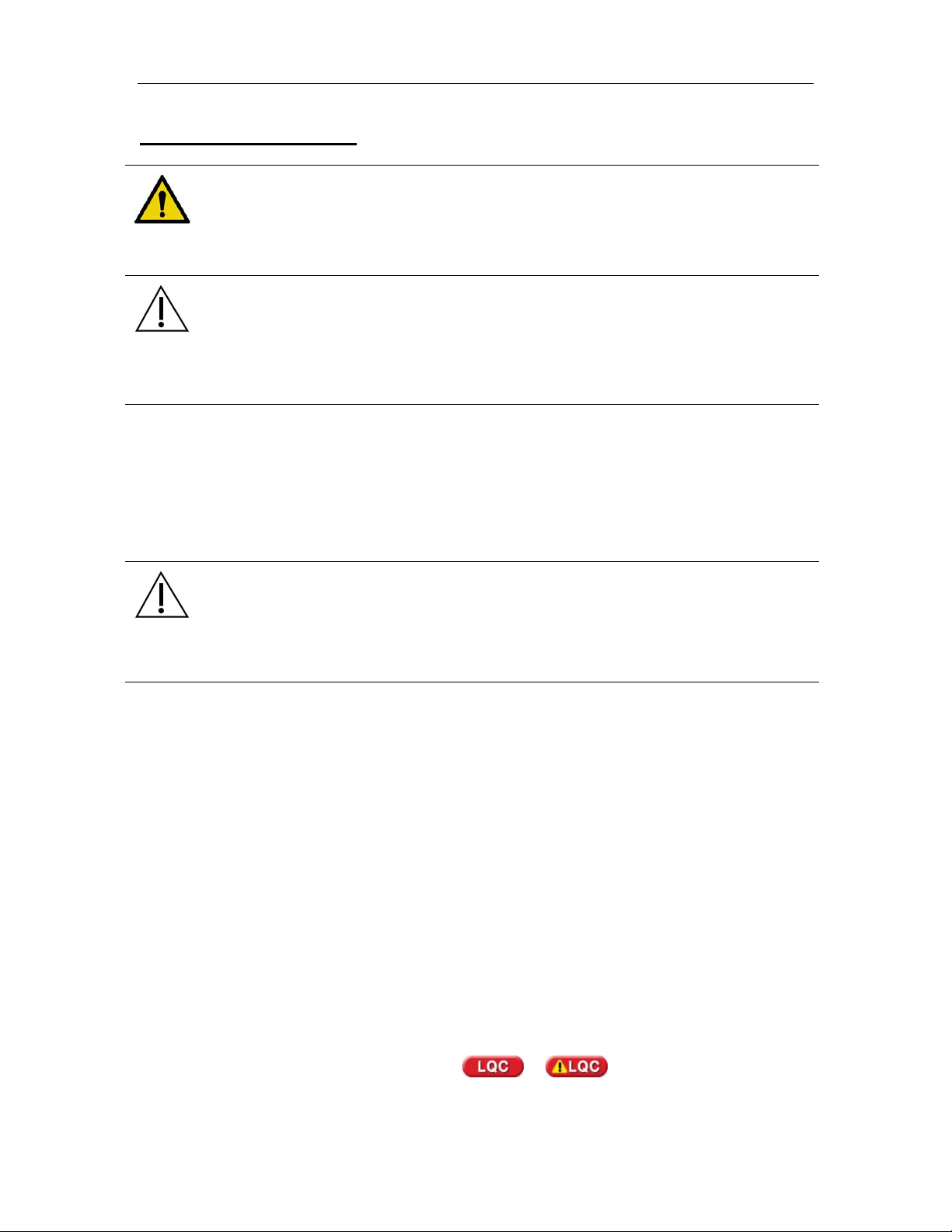
3M™ Rapid Detection Reader Warnings and Precautions
Warnings and Precautions
Read all contents of this manual prior to use.
The following symbols are used on the 3M Rapid Detection Reader, related components and
accessories, or in the text of this user manual:
WARNING!
Indicates a hazardous situation, which if not avoided, could result in death or injury,
e.g., fire, electrical shock or explosion.
WARNING! Hazardous Voltage
CAUTION. Indicates a situation, which if not avoided, could result in damage to the
device.
Consult Accompanying Documents
Consult Operator Manual
1
Page 7
3M™ Rapid Detection Reader Warnings and Precautions
Summary of Warnings and Precautions
The 3M Rapid Detection Reader and its related devices and accessories are designed to provide
safe and reliable service when used according to the instructions provided in this Operator
Manual.
The following warnings and precautions should be followed in order to avoid unsafe actions with
the 3M Rapid Detection Reader that could potentially result in personal injury or device damage.
WARNING!
To reduce the risk associated with hazardous voltage:
• Unplug the 3M Rapid Detection Reader before cleaning.
• Do not disassemble the 3M Rapid Detection Reader or any of its related
components and accessories. The instrument contains no operator-serviceable
components.
• Do not immerse any of the 3M Rapid Detection Reader components in any liquid.
• Do not use the 3M Rapid Detection Reader if there is apparent damage to a power
cord or power supply.
To reduce the risk associated with potentially infectious patient samples:
• Do not spill specimen or sample fluids on any of the 3M Rapid Detection Reader
components or on the outside of the Test Cartridge.
• If a spill occurs, disinfect external surfaces only, using a soft cloth containing a
solution of 0.5% bleach, 70% isopropyl alcohol or 70% ethanol.
CAUTION.
To reduce the risk associated with incorrect results:
• 3M Rapid Detection Reader should only be used by trained professionals and
operated in accordance with facility policies and procedures.
• 3M Rapid Detection Reader should only be operated in ambient temperature
conditions between 15-30°C (59-86°F) and out of direct sunlight.
To reduce the risk of instrument or accessory damage:
• 3M Rapid Detection Reader is not designed to withstand moisture, temperature
extremes, severe shock or vibration.
• 3M Rapid Detection Reader is intended for use indoors, located on a stable,
stationary surface such as a counter top.
• Do not open any 3M Rapid Detection Reader device enclosures, this will void the
warranty.
To reduce the risk associated with environmental contamination:
• Dispose of instrument and accessories in accordance with federal, state, and local
requirements.
2
Page 8

3M™ Rapid Detection Reader Introduction
Introduction
Overview
The 3M Rapid Detection Reader is a rapid immunochromatographic system for performing in vitro
diagnostic analyses.
The 3M Rapid Detection Reader is comprised of the 3M Rapid Detection Control Module (CM)
and the 3M Rapid Detection Test Module (TM). Each Test Module has two ports. Up to three
Test Modules are connected to each Control Module providing the user the ability to test 1-6
samples simultaneously. The configuration software and USB flash provided drive allow the user
to customize the Reader and maintain the test data. The optional barcode scanner and printer
provide ease and accuracy for data entry and record keeping.
Calibration and expiration information for Test Cartridges are input to the 3M Rapid Detection
Control Module (CM) through Lot Cards enclosed with the Test Kits.
To perform an assay, the operator places a sample into the well of a Test Cartridge and inserts
the Test Cartridge into the 3M Rapid Detection Test Module (TM).
Once the Test Cartridge has been inserted, no further intervention is required. A barcode on the
bottom of the Test Cartridge is read to determine the Test Kit lot number. Information loaded with
the Lot Card identifies lot specific parameters and expiration date. This ensures that an expired
cartridge is not used.
Analysis time is analyte specific and typically less than 20 minutes per sample. Results may be
viewed on the 3M Rapid Detection Reader display screen and/or output to the USB flash drive, a
printer, or network.
The 3M Rapid Detection Reader only accepts Test Cartridges specified for use with 3M Rapid
Detection Test Kits.
The 3M Rapid Detection Reader can operate in either local or network mode. Operator input is
accepted from the touch screen or an optional barcode scanner. Stored data including results
can be transferred via USB flash drive or sent to a printer or network file.
Intended Use
The 3M Rapid Detection Reader is a general use fluorometer that analyzes results produced by
immunoassays specified by 3M.
Full operation requires the use of 3M RAPID DETECTION Test Kit. Optional accessories include
a printer and barcode scanner.
3
Page 9

3M™ Rapid Detection Reader Unpacking and Setup
Unpacking and Setup
Inspect all components carefully. If any damage is visible, notify the carrier and your distributor or
3M to arrange for repair or replacement.
3M Rapid Detection Reader Components
Item Description
3M RAPID
DETECTION
Control Module
(CM)
Catalog # 3960
3M RAPID DETECTION Control Module
Operator Manual
Reader Configuration Utility CD
Power Supply*
USB Flash Drive**
3M RAPID
DETECTION
Test Module
(TM)
Catalog # 3968
*Only use the approved power cord provided with the 3M RAPID DETECTION CM. A power cord
approved for the North American market will be provided with each CM. Outside the North
American market, the CM will be supplied with an additional power cord approved for that market.
**Use manufacturer supplied USB Flash Drive. If a USB Flash drive is supplied by the operator,
ensure the drive folders match those folders listed in the Manually Transferring / Printing Results
or Logs section.
3M RAPID DETECTION Test Module
Interconnect Cable
Optional Accessories (Available from 3M)
Optional USB devices supported by the 3M Rapid Detection Reader include a printer and a
barcode scanner. Only use the approved USB cables supplied with these devices.
NOTE: Only one of each type of device can be connected to the CM at any given time.
Item Description
Printer
Catalog # 3965
Printer for self-adhesive roll labels, 2 - 2.5-inches
wide. Connects to the CM via USB. Zebra®
Technologies TLP 2824™.
Consumables:
Requires 2.25” W x 3” L Z-Select 4000T labels from
Zebra® Technologies (p/n: 800222-305).
Requires 57mm x 74m Wax/Resin Ribbon from
Zebra® Technologies (p/n: 800132-102).
Additional information available at www.zebra.com
or 1.847.634.6700.
4
Page 10

3M™ Rapid Detection Reader Unpacking and Setup
Item Description
Barcode Scanner
Catalog # 3967
Omni-directional, hands-free barcode scanner with
cradle for entering Operator and Patient/Sample ID.
The barcode scanner is shipped in the correct
configuration and is ready for use after connecting to
the CM via USB. Symbol Technologies Inc. model
LS9208. Additional information available at
www.symbol.com, 1.800.653.5350 or
1.631.738.2400.
3M Rapid Detection Reader Setup
The 3M Rapid Detection Reader is comprised of:
§ 3M RAPID DETECTION Control Module (CM)
User interface and connectors for all peripherals. Stores and displays test results (view, print,
transfer, search, filter/sort)
§ 3M RAPID DETECTION Test Module (TM)
1 – 3 TMs per CM
Each TM has two test cartridge ports for performing simultaneous 3M RAPID DETECTION
Tests
§ 3M RAPID DETECTION Reader Configuration Utility Software (RCU)
CD allows customized settings for the 3M Rapid Detection Reader
§ Power supply and interconnect cable
§ USB flash drive
Pre-configured with 4 subdirectories (folders) named: patient, lqc, iqc and log, for use in bidirectional information transfer in a non-networked environment. Also contains “File
Converter 1_1.xls”. See Manually Transferring/Printing Results or Logs section.
To set-up 3M Rapid Detection Reader:
1. Place the 3M Rapid Detection Reader components on a stable work surface within reach of
an electrical outlet. Access to the back of each module is required to connect components.
2. Remove dust protection stickers from TM ports
3. Connect the TM and any optional devices to the CM using the supplied interconnect cable(s).
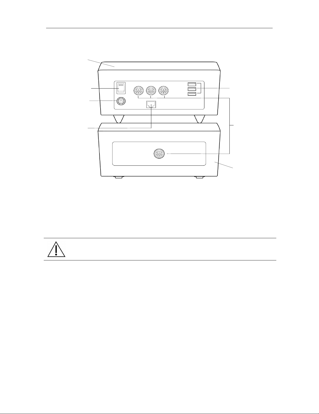
Refer to Figure 1 for connector locations.
Refer to manufacturer’s instructions for optional printer or barcode scanner for additional
information on set-up for these accessories.
4. Connect the supplied power cord to the CM. Plug the other end into a wall socket.
5
Page 11
3M™ Rapid Detection Reader Unpacking and Setup
3M Rapid Detection
Control
Module
Power On/Off
Power cord
Ethernet
connector for
3M Rapid
Detection Reader Test
USB connectors for
Figure 1. 3M Rapid Detection Reader - Rear View Showing Connectors and Power Switch
Reader
optional printer,
optional barcode
scanner and Flash
Drive
port
3M Rapid Detection
Reader Control
connection
to a network
Module to 3M Rapid
Module port
Detection Reader
Test Module
NOTE:
• 1, 2, or 3 TMs can be connected to each CM
• TMs can be stacked
• CM can be placed on top of the TM
• Do not place anything on top of the CM.
CAUTION.
Do not stack CM on top of TM unless all four feet are in place.
6
Page 12
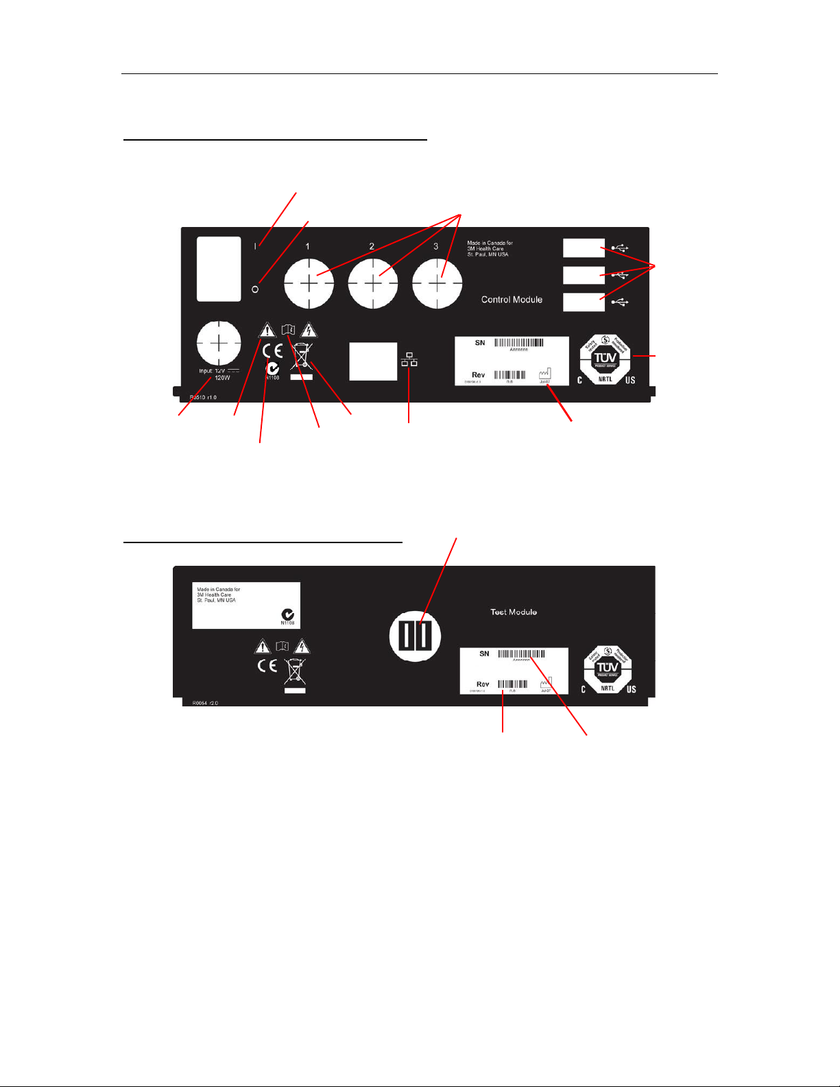
3M™ Rapid Detection Reader Unpacking and Setup
0 - OFF Switch
Safety
Date of
Ethernet
Electrical
Consult
manual
Hardware
Serial
Figure 1a. 3M Rapid Detection Reader – Rear view panel labels and description
3M RAPID DETECTION Control Module
I - ON Switch
TM Ports
USB Ports
certification
marking
Caution
rating
CE Marking
WEEE
connection
3M RAPID DETECTION Test Module
CM Port
revision
number
manufacture
number
7
Page 13
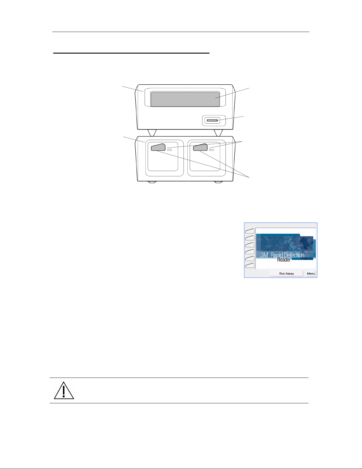
3M™ Rapid Detection Reader 3M Rapid Detection Reader (MODULES)
Touch
Lot Card
Test Cartridge
3M Rapid Detection Reader (MODULES)
Figure 2. 3M Rapid Detection Reader Features - Front View
Control Module
Screen
Display
Insertion Slot
Test Module (3 max)
Port LEDs
Ports
Turning on the 3M Rapid Detection Reader
The power On/Off switch is located on the rear panel of the CM
(Figure 1). When the power is switched on, the 3M Rapid Detection
Reader performs a number of internal self-tests, including IQC, to
ensure the system is operating within specifications. For additional
information, refer to Running Quality Control section.
When switched ON, the LEDs on the front of the TM illuminate blue.
When the power-on sequence is complete, the Home screen is
displayed (Figure 3). The power-on sequence takes approximately
1 minute.
Once the Home screen is displayed, selections can be made by
touching the appropriate prompt on the display (i.e., Run Assay to
initiate an assay, or Menu to go to the Main Menu screen (Figure 4)).
The display is touch-sensitive and can accept input from a bare/gloved
finger or a blunt stylus.
The 3M Rapid Detection Reader can be operated immediately after
set-up using the pre-programmed default settings. The date, local
time and some settings can be edited manually through the Settings
menu on the CM touch screen. Most settings can be edited using the
Reader Configuration Utility (RCU) supplied with the CM. For
additional information on editing user settings, refer to Managing
Settings and Editing Settings Using the Reader Configuration Utility
(RCU).
Figure 3. Home
CAUTION.
Pens or other sharp instruments will damage the touch screen.
8
Page 14
3M™ Rapid Detection Reader 3M Rapid Detection Reader (MODULES)
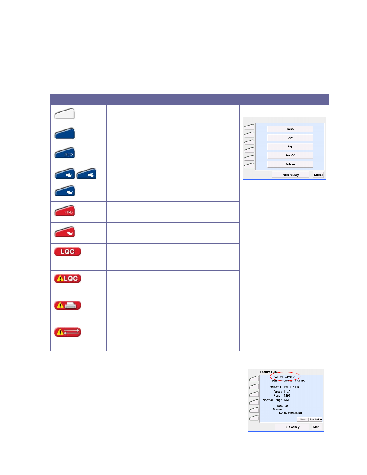
Display Icons
The left hand column of the screen displays an icon for each available port. Touching these icons
leads to a full screen display of the status of that port.
The lower left corner of the display screen, below the port icons, displays LQC, Printer and
Communication warning icons.
The meaning of the displayed icons is as follows:
Icon Meaning
(Non-selectable)
(Non-selectable)
Port Idle
Port Busy
Assay Timing
Sample processing and cartridge movement
Error – (HRB for example only). For detailed
information see Troubleshooting
Aborting assay, cartridge ejecting, error
message to follow
Liquid Quality Control Warning
See Running Quality Control
Liquid Quality Control Expired Warning
See Running Quality Control
Figure 4. Main Menu
(Non-selectable)
(Non-selectable)
Printer Error
See Troubleshooting
Data Transfer Error
See Transferring Results or Troubleshooting
Port Identification Nomenclature
Ports on the 3M Rapid Detection Reader are identified by a multicharacter nomenclature system. The first set of characters is the
serial number of the TM; the last character is a letter (A or B) referring
to the left (A) or right (B) port for a particular TM. This is displayed at
the top of the screen (Figure 5) when the port icon is touched or if
there is an IQC port error and in the IQC results log.
9
Figure 5. Port Identification
Page 15
3M™ Rapid Detection Reader Performing an Assay
Performing an Assay
WARNING!
To reduce risk to the operator:
• Observe local protocols and appropriate precautions in the collection, handling,
and disposal of specimens.
CAUTION.
• When entering data via the CM touch screen (e.g., Sample/Patient/User ID), enter
characters one at a time as failure to do so may result in erroneous data entry.
• Be familiar with all of the instructions in the Test Kit Package Insert including
Warnings and Precautions prior to performing an assay.
Using Lot Cards
The Lot Card provides lot specific information and the expiration date for each Test Kit and is only
required to be read once for each Test Kit lot. Prior to performing any assay, insert the Lot Card
for that Test Kit lot into the Lot Card Insertion Slot (Figure 2). The CM can store information from
50 different Test Kit lots. If the maximum is exceeded, the oldest entry is overwritten.
CAUTION.
To avoid damaging the Lot Card:
• Do not touch the contact pads on the Lot Card.
• Store the Lot Card in the anti-static pouch provided.
To use the Lot Card:
1. Remove the Lot Card from the anti-static pouch.
2. Hold the Lot Card so that the arrow is on the top side and pointing away.
3. Insert the Lot Card, contact end first, into the slot located on the front of the CM.
4. The display provides status messages: Reading Lot Card, Complete, Lot ID: XXX,
Remove Lot Card.
5. Remove Lot Card and store in its original pouch.
6. If an error message is displayed, or if there is no response to insertion of a lot card, refer
to the Troubleshooting Section.
7. Keep the Lot Card for the life of the Test Kit.
Starting an Assay
NOTE: The default setting of the 3M Rapid Detection Reader does not require an Operator ID or
password. These login requirements can be edited via the Edit Operator settings menu or RCU
(See Managing Settings). If using default settings, Figure 6 will not appear.
If the following Liquid Quality Control warnings or appear, refer to Running
Quality Control.
10
Page 16
3M™ Rapid Detection Reader Performing an Assay
NOTE: The message Lot # XXX Not Found, Insert Lot Card or Cancel will be displayed if a
Test Cartridge is inserted and the Lot Card data is not stored in the CM. The Lot Card must be
inserted within 40 seconds or the assay will be aborted. Touch OK to return to the Home screen.
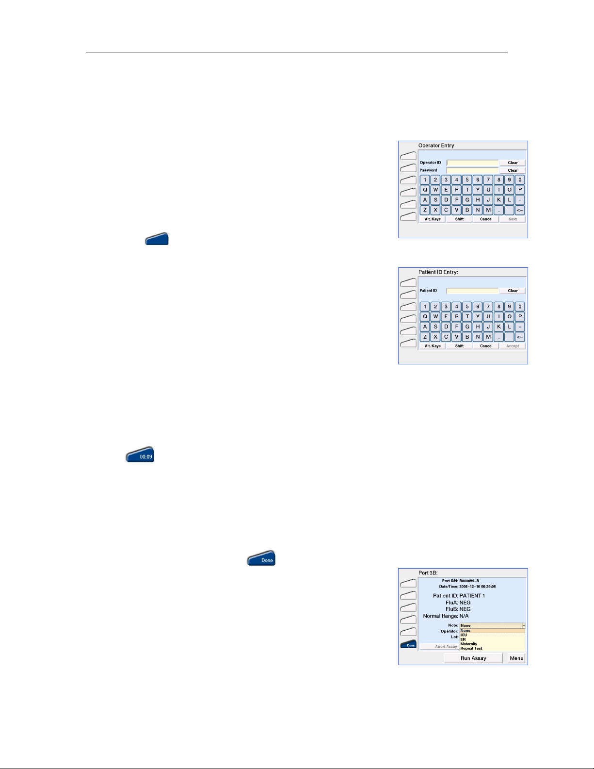
1. Touch Run Assay. If prompted, enter Operator ID and/or
Password (Figure 6) using either the touch screen or the barcode
scanner. To accept the displayed information, touch Accept.
Figure 6. Operator Entry
NOTE: The Operator ID and Password entries are casesensitive.
2. When prompted, enter the Patient ID/Sample ID using either the
touch screen or barcode scanner (Figure 7). Touch Accept.
3. When prompted to Add Sample & Insert the Test Cartridge, the
LED on a free port of the TM will flash blue and the corresponding
port icon on the display will illuminate blue (Refer to Test
Kit Package Insert for detailed instructions on sample handling).
4. Prepare Sample and Test Cartridge as stated in the Test Kit
Figure 7. Patient ID Entry
Package Insert and insert Test Cartridge into the flashing port.
If the cartridge is not inserted within 5 minutes of the Add
Sample & Insert prompt, the system will time-out. Touch OK to
return to the Main Menu.
NOTE: The Test Cartridge must be inserted into the TM within
~30 seconds of sample application. Otherwise, FAIL will be
displayed in the port icon and the assay will be aborted.
Do not use excessive force when inserting the Test Cartridge. The TM will guide the Cartridge
into place.
NOTE: If the cartridge won’t fit or won’t enter the cartridge port, clear the cartridge port of any
obstruction or blockage.
Once the Cartridge Inserted message clears, the previous screen is displayed and the active port
icon shows a timer that counts up until sample flow is detected, then counts down until the
assay is complete.
Another assay can be started once Assay Initialization is complete by touching Run Assay.
5. To check the assay progress, touch the port icon. The details of the assay will be displayed.
Touch Exit to return to the previous screen. Touching Abort Assay will cause the cartridge to be
ejected and a Failed Assay to be recorded in the Events Log.
6. When an assay is complete, the Test Cartridge is ejected and the
corresponding port icon displays . To view the test details
touch the icon.
Figure 8. Results, prior to
cartridge removal
7. Before removing the Test Cartridge from the TM, a predefined
note can be added to the result from the drop down menu on the
Result Details screen (Figure 8). Once the Test Cartridge is
removed, a note cannot be added or changed.
Up to 10 notes can be defined using the RCU (Refer to Editing
Settings Using the Reader Configuration Utility section).
8. Remove the Test Cartridge and discard according to local
hazardous waste policy.
11
Page 17
3M™ Rapid Detection Reader Running Quality Control
Running Quality Control
Two types of quality control test records are stored by the 3M Rapid Detection Reader:
• LQC (Liquid Quality Control) - external surrogate sample test results.
• IQC (Internal Quality Control) - self-diagnostic test results including a check of the power
supply voltage, system memory, cartridge transport system, cartridge barcode sensor, LED
function, and incubator function for heated assays.
Running LQC
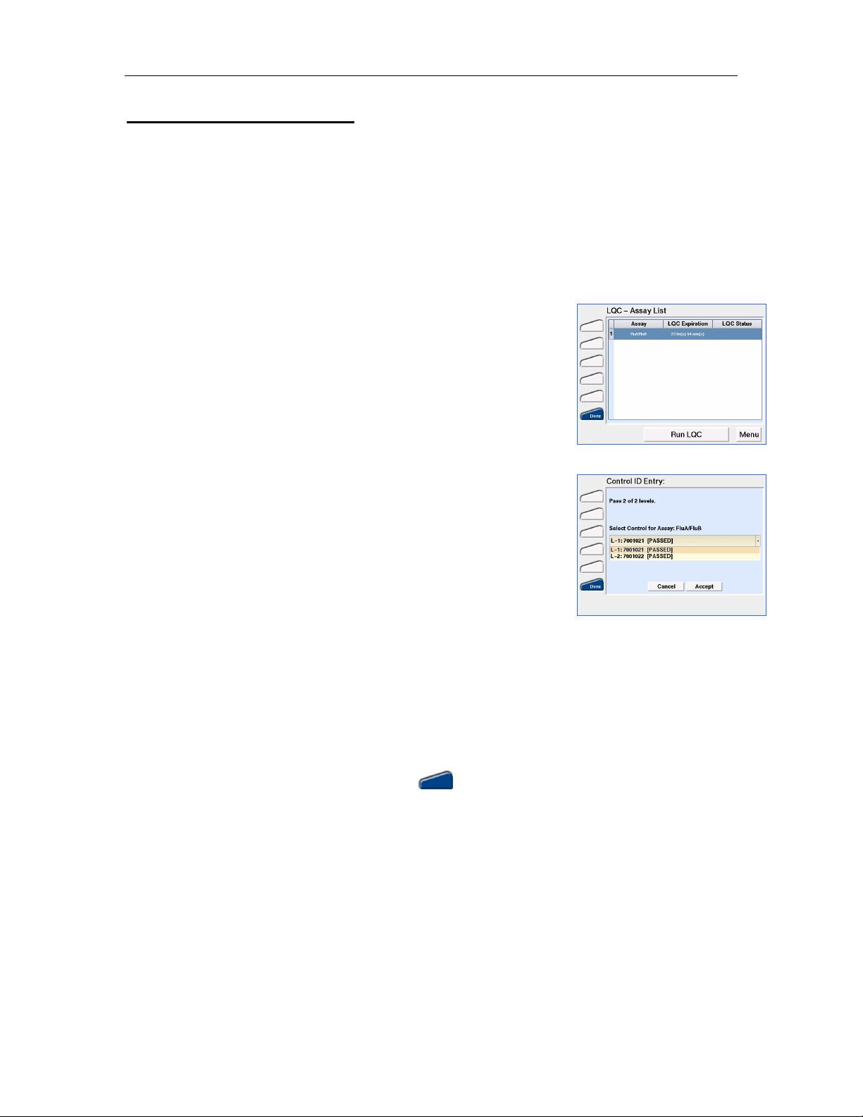
1. From the Main Menu screen (Figure 4) touch LQC. The LQC –
Assay List screen will open (Figure 9). This screen will display
the entire list of assays sorted in ascending order by the Time to
Figure 9. LQC - Assay List
Expiry before assay lockout as displayed in the LQC Expiration
column. If LQC is due, this column will display “Run x of y levels”
where x is the number of levels required and y is the number of
defined LQC levels for that assay. Both the number of levels
required and the available defined levels are set using the RCU.
The LQC status column shows the requirements for any LQC
levels that have failed. If any LQC fails, that specific control level
must be run successfully prior to proceeding with a patient’s test.
If the maximum number of Failures before LQC Lockout is
reached, this column will display “LQC Lockout”.
Figure 10. Control ID Entry
NOTE: The assay list is defined in RCU. Any new assays added
in the RCU or through the CM will default to LQC disabled and
will be listed with N/A in the LQC Expiration column. Refer to the
RCU Help Manual for further instruction.
2. Select the assay for which LQC will be performed. Touch Run
LQC. If prompted, enter Operator ID and/or Password using
either the touch screen or the barcode scanner. To accept the
displayed information touch Accept.
NOTE: Both the Operator ID and Password are case-sensitive.
3. When prompted (Figure 10), select the appropriate Control ID using the drop down menu. Touch
Accept.
NOTE: If LQC has failed for the assay selected, the number of LQC attempts allowed prior to
assay lockout is displayed.
4. When prompted to Add Control & Insert the Test Cartridge, the LED on a free port of the TM will
flash blue and the corresponding port icon on the display will illuminate blue (Refer to Test
Kit and Quality Control Package Inserts for detailed instructions).
5. Prepare Test Cartridge as per Test Kit Package Insert and insert Test Cartridge into the flashing
port.
If the cartridge is not inserted within 5 minutes of the Add Control & Insert prompt, the system
will time-out and return to the Main Menu.
NOTE: The Test Cartridge must be inserted into the TM within ~30 seconds of sample
application. Otherwise, FAIL will be displayed in the port icon and the assay will be aborted.
12
Page 18

3M™ Rapid Detection Reader Running Quality Control
Do not use excessive force when inserting the Test Cartridge. The TM will guide the Cartridge
into place.
Once the Cartridge Inserted message clears, the previous screen is displayed and the active port
icon shows a timer that counts up until sample flow is detected, then counts down until the
assay is complete.
NOTE: Touching Run Assay or Run LQC will start another assay/LQC and the test sequence
will begin again using a different available port. The assay progress can be checked by touching
the port icon. Touch Exit to return to the previous screen.
6. When an assay is completed, the corresponding port icon displays and the Test Cartridge
is ejected. Touch the icon to view the test details.
7. Remove the Test Cartridge and discard according to local hazardous waste policy.
LQC Icons
Icon Meaning
LQC will be due shortly. Appears when the LQC timer for an assay has less than the
user defined % of time remaining until lockout.
LQC has expired for one or more assays. If icon is
displayed, the Assay Status Warnings screen
(Figure 11) will display upon touching the Run Assay
Figure 11. Assay Status Warnings
button. Touch Continue if the desired assay is not
listed.
A limited number of overrides can be configured via
the RCU. If overrides are available, touch Continue
to override lock out (i.e., perform a patient test after
LQC is due). The decision to use an Override will be
confirmed (Figure 12). Once all overrides have been
used, LQC must be performed prior to any further
patient testing. If an assay with no overrides is
inserted into the TM, an LQC Overdue, Assay
Figure 12. Override Confirmation
Locked warning will display and the assay will be
aborted.
NOTE: These warnings are display only and are not selectable. To determine the assay(s) for
which LQC is due, view the LQC – Assay List (Figure 9).
NOTE: If there is more than one level of LQC defined for an assay, and LQC has expired for this
assay, the LQC timer will be reset to the time at which the earliest LQC level passes in the set.
e.g.: Two levels of QC are required, Level 2 passes LQC but Level 1 fails; once Level 1 is
repeated and passes, the "Time to Expiry" column in the LQC menu will display the count down
from the time when Level 2 passed.
13
Page 19

3M™ Rapid Detection Reader Running Quality Control
Running IQC
IQC runs automatically every time the 3M Rapid Detection Reader is turned on. IQC can also be
initiated manually or configured to run at predefined intervals. IQC takes less than 1 minute to
complete.
When IQC is initiated, the appropriate tests are performed on each port in each attached TM.
IQC verifies the power supply voltage, system memory, cartridge transport system, LED function
and incubator function for heated assays. During IQC the system also determines system power,
verifies the system clock and verifies the Reader calibration.
Should there be a test in progress in a port, IQC will begin for that port once the test cartridge is
removed on assay completion. Results of the IQC are stored for each cartridge port in the IQC
results database.
To run IQC manually:
1. From the Main Menu screen (Figure 4), touch Run IQC. If
prompted, enter the Operator ID and/or Password using either the
touch screen or barcode scanner. To accept the displayed
information, touch Accept. The IQC Status screen is displayed
(Figure 13).
Figure 13. IQC Status
NOTE: Both the Operator ID and Password are case-sensitive.
IQC is started on all idle ports and will automatically start as ports
become free.
2. Touch OK to return to the Main Menu. If IQC fails, the TM port
LED illuminates red, the port icon turns red and the failed port can
no longer be used. e.g.,
To run IQC automatically:
To run IQC automatically at predefined intervals, the Reader is configured using the RCU or the
CM.
To configure the Reader to run IQC at defined intervals through the RCU, refer to Editing Settings
Using the Reader Configuration Utility (RCU) section.
To configure the Reader to run IQC at defined intervals through the CM, refer to the Managing
Settings section.
14
Page 20

3M™ Rapid Detection Reader Working with Results and Logs
1. From the
Main Menu
screen
(
Figure 4
), touch
Log
. If prompted,
Working with Results and Logs
The 3M Rapid Detection Reader can store up to 900 results (300 assay results, 300 LQC results
and 300 IQC results). When the CM database is full, the oldest result is over-written. Dual
analyte assay results are stored as two separate patient records. IQC results are stored
separately for each individual test port.
In manual transfer mode only (i.e., when 3M Rapid Detection Reader is not connected to a
network), the warning “Database Almost Full, Backup Data” will be displayed when the assay or
LQC result databases have less than 20 spaces left. This message will continue to be displayed
until the database is cleared.
In auto transfer mode, only new results that have not been previously transferred are transferred
during an upload. Data is not deleted from the CM upon transfer.
The 3M Rapid Detection Reader can store up to 500 Log records (including system power up,
upload/download of data, assay and LQC errors). When the database is full, the oldest result is
over-written. A warning message is not displayed when the Log database is full.
Viewing Saved Results
1. From the Main Menu screen (Figure 4), touch Results. If
prompted, enter Operator ID and/or Password using either the
touch screen or the barcode scanner. To accept the displayed
information, touch Accept.
Figure 14. Assay Results
NOTE: Both the Operator ID and Password are case-sensitive.
The screen displays a list of all Assay Results (Figure 14). The
most current assay result is the first listed. For each assay result,
the Patient ID, assay name, result value, and date/time is
displayed.
To view a list of LQC or IQC results, touch the circle next to the
words LQC Results or IQC Results (in the display header) to
specify the type of results to be viewed. The list of results will be
displayed.
2. To view the details of a particular result, touch the result, and
then touch View. To return to the result list, touch Results List.
Viewing Saved Logs
enter Operator ID and/or Password using either the touch screen
or the barcode scanner. To accept the displayed information,
touch Accept.
NOTE: Both the Operator ID and Password are case-sensitive.
Figure 15. Results Detail
Figure 16. All Events
A list of all events will be displayed (Figure 16). The most recent
event is listed first. For each event, the Date/Time is displayed.
To view a list of assay or LQC errors only, touch the circle next to
the words Failed Assays or Failed LQC (in the display header)
to specify the type of results to be viewed. The list of events will
15
Page 21

3M™ Rapid Detection Reader Working with Results and Logs
be displayed.
To view the details of a particular event, touch the event, and
then touch View.
2. To return to the event list, touch Events List.
Searching Results
Result Type Search Options
Assay
LQC
IQC
Operator Name Sample/Patient ID Assay Name
Operator Name Control ID Assay Name
Operator Name Port
1. From the Assay (or IQC or LQC) Results screen, touch Search to
open the Search Assay Results screen (Figure 17).
2. Use the drop down arrow € on the Operator Name to change the
Figure 17. Search Assay Results
search parameter.
3. Use the touch screen or barcode scanner to enter the desired
value to search. Touch Alt. Keys or Shift to display extended
character sets.
NOTE: Enter the first few characters or the entire name or ID to
be found.
4. Touch either All Results or Date Range. All Results is the default
setting. When Date Range is touched, the From/To Y M D fields
become active. Enter the desired dates in YYYY MM DD format.
5. Touch Search to generate a list of results based on the search criteria entered or touch Cancel to
clear the search criteria and return to the main Results screen.
6. If no results matching the search criteria are found, Empty Search will be displayed.
7. When viewing the records for a particular search, touch View All to return to viewing the complete
Results list.
Searching Logs
Log Type Search Options
All Events
Failed Assays
Failed LQC
Operator Name
Operator Name Sample/Patient ID Assay Name
Operator Name Control ID Assay Name
Follow the directions above for Searching Results.
Event Text (enter any part of field, not casesensitive)
16
Page 22

3M™ Rapid Detection Reader Working with Results and Logs
Manually Transferring / Printing Results or Logs
Results (assay, patient or IQC) that have been selected on the Results screen can be transferred
to a printer, USB flash drive or to a network. It is important to note that the user should manually
delete the results from the Reader after manual transfer or they will be transferred again, unless a
specific range of results is selected when the next manual transfer is performed.
Log events (All, Failed Assays or Failed LQC) that have been selected on the Events screen can
be transferred to a USB flash drive or to a network. Only Failed Assays and Failed LQC can be
printed from the CM.
NOTE: A single USB flash drive can be used to transfer results from all Readers as the file
names start with their respective control module serial numbers. The USB flash drive must be
preconfigured with 4 subdirectories (folders) named: patient, lqc, iqc and log, for this use.
CAUTION.
Do not remove the USB flash drive from the control module while data is being
transferred.
1. From the Assay Results (Figure 14) or All Events (Figure 16)
screen, select record(s) by touching the desired record(s). Touch
Transfer to open the Results or Events Transfer screen (Figure
18 shows results transfer as an example).
Figure 18. Results Transfer
IQC and LQC results or failures can be transferred or printed in
the same manner from their respective screens.
2. On the Results or Events Transfer screen, touch Print, USB or
Network as desired. On the Events Transfer screen, touch
USB or Network as desired. Only options for which the
connections are available will be functional.
3. Confirm the transfer by touching Confirm. Touch Cancel to
Figure 19. Result Transfer
Confirmation
abort transfer. (Figure 19)
When the transfer is complete, touch OK and the Results screen
(or Events screen) will be displayed. If transfer fails the
warning icon and a failure message are displayed, touch OK to
return to Results or Events screen (the screen depends on the
previous context, e.g., if transferring LQC results, then LQC
Results screen will be shown).
Once results have been transferred, File Converter 1_1.xls on the
supplied USB flash drive may be used to convert the data files to
an Excel format.
Open the file “File Converter 1_1.xls”, enable Macros, and follow the directions on the screen.
You will be prompted to save the Excel-formatted file.
NOTE: File Converter 1_1.xls must be used for this purpose. Data will not be formatted properly
if an earlier version of File Converter.xls is used.
17
Page 23

3M™ Rapid Detection Reader Managing Settings
Managing Settings
The 3M Rapid Detection Reader can be operated immediately after set-up using the preprogrammed default settings. Each Reader also has customizable features which can be
configured to enhance its functionality and data management capability. Customizable features
include LQC timer, Operator ID and password, and data transfer options (USB, print, network).
Some of these features can be configured in the CM Settings menu. In the default configuration,
these settings can only be viewed or changed by an operator with Supervisor access. Most
feature configurations are set using the Reader Configuration Utility (RCU) by a Full Access User.
For instruction on configuring settings on the CM, refer to Edit Settings and Edit Operators. For
instructions on configuring settings using the RCU, refer to Editing Settings Using the Reader
Configuration Utility (RCU).
Feature (See Detailed
Descriptions Below)
Assay defaults √
LQC √
Update / Upload Features √
Printer Settings √
Full Access User
Edit on RCU
Supervisor
Edit on CM
Login Requirements √ √ (limited)
File Settings √ √
Menu Idle / Timeout √
Date / Time (without Network
NTP only √
Time Protocol – NTP)
Language √
Auto IQC Interval √ √
Network Transfer Timers √
Sound √
Accessing the Settings Menus
From the Main Menu (Figure 4), touch Settings. Access to the
Settings menu is Operator ID and Password protected. The default
login for access to the Settings menus is:
Operator ID: SUPERVISOR
PASSWORD: PASSWORD
Both entries are case-sensitive. To provide additional security, it is
highly recommended that this login be changed.
Figure 20. Settings Menu
NOTE: The default privilege access to the Settings menu is Supervisors only (Figure 25). The
privilege access to this menu can only be changed via the RCU. In the default setting, any operator
defined in the Operator List as Supervisor [Operator Type] is able to access the Settings menu. Refer
to Managing Operators for additional information.
Touch View Settings from the Settings menu (Figure 20). This will open the screen shown in Figure
21. Settings in the View Settings screen cannot be edited.
18
Page 24

3M™ Rapid Detection Reader Managing Settings
Settings: View Tabs
Tab Screen
Assay
Edit through RCU only.
Sample/Patient ID
Purpose: Define the field name as Patient ID or Sample ID.
Default: Patient ID.
String length can be set from 1 to 18.
Default: Min Length 1, Max Length 18.
New Assay Lockout
Purpose: Define ability of operators to perform assays not in the
assay list. The assay list is displayed on the LQC-Assay List
screen (Figure 9). Set as either Yes or No.
Yes: End users cannot run any assays that are not on the RCU
defined assay list.
No: End users can run any 3M Rapid Detection Reader assay.
Default: No.
Predefined Notes
Purpose: Define up to 10 notes that an operator can attach one
of these notes to each patient test result prior to removing the
Test Cartridge from the TM. The Note becomes part of the result
record when the Cartridge is removed from the TM.
Figure 21. Settings: View Assay
Tab
NOTE: The predefined note can be up to 20 characters in length.
Make sure the note entered through the RCU is less than or
equal to 20 characters in length.
LQC
Edit through RCU only.
Default: Timer Reset (hours) = 0, LQC will not time-out.
Hide Numeric LQC Results
Purpose: To Hide LQC results and report only PASS/FAIL
Yes: Pass/Fail will be displayed in place of results.
No: Actual result will be displayed.
Default: No.
LQC Timeout Warning (% remaining)
Purpose: Define the percentage of the LQC interval remaining (if
LQC Timer is set in RCU) before LQC expires for any assay.
Default: 10%.
Figure 22. Settings: View LQC Tab
19
Page 25

3M™ Rapid Detection Reader Managing Settings
Settings: View Tabs
Tab Screen
LQC continued
Max Failures Before Lockout
Purpose: Define the number of LQC failures allowed before the
assay is Locked Out when LQC Timer is set in RCU. LQC
Failure count is reset upon successful completion of LQC. Can
be set from 1-9.
Default: 9.
Control ID
Purpose: Define control IDs.
Default: Min length 1, Max length 18.
Timer
The ability to edit the settings of the TIMER tab varies by item
and is defined below.
Timer Intervals
Menu Idle Timeout
Edit on CM. Cannot edit through RCU.
Purpose: Define the amount of idle time before the 3M Rapid
Detection Reader returns to the Home screen.
Range: 1 -10 minutes.
Default: 5 minutes.
Update/Upload Start Date/Time
Edit through RCU only.
The date and time used to calculate the start of the following
intervals.
Update Interval
Edit through RCU only.
Purpose: Interval at which the Reader checks for changes to
settings in a networked environment. Disable by entering 0.
Figure 23. Settings: View Timer
Tab
Range: 0 – 1440 minutes.
Default: 1.
Upload Results Interval
Edit through RCU only.
Purpose: Interval at which the Reader sends changes or
additions to the result and event logs in a networked environment.
Disable by entering 0.
Range: 0 - 1440 minutes.
Default: 0 (Disabled).
20
Page 26

3M™ Rapid Detection Reader Managing Settings
Settings: View Tabs
Tab Screen
Timer continued
NOTE: Only new results that have not been previously
transferred are transferred during an upload. Data is not deleted
from CM upon transfer. When the CM database is full, the oldest
result is over-written.
NOTE: It is important that the upload interval be set to ensure
data capture and transfer prior to records being overwritten.
Auto IQC Interval
Edit on CM and through RCU.
Purpose: The interval between automatic IQC self-diagnostics in
either local or networked environment. Disable by entering 0.
Range: 0 – 1440 minutes.
Default: 0 (Disabled).
Printer
Edit through RCU only.
Auto Print
Purpose: Defines if automatic printing is enabled. Settings are
independent for assay, LQC and IQC results.
On: Result will automatically print upon completion.
Off: Result will not print automatically.
Default: Off.
Print Headers
Purpose: Define customized print header information that will be
visible on every printout.
Login
Edit through RCU only.
Device Name
Purpose: Define name assigned to the device.
Default: Blank.
Lockout
Figure 24. Settings: View Printer
Tab
Figure 25. Settings: View Login
Tab
Purpose: Disable Reader.
Device Locked: Assays cannot be run.
Device Unlocked: Assays can be run (Default).
21
Page 27

3M™ Rapid Detection Reader Managing Settings
Settings: View Tabs
Tab Screen
Login continued
Login Requirements
Purpose: Define login requirements independently for Operators
and Supervisors requiring None, ID and Password, ID only or
Password only. If None, an Operator ID cannot be entered when
running assays.
Default: Operators – None, Supervisors – ID and Password.
Privilege Requirements
Purpose: Defines the access privileges for each level user.
All Operators: Operators and Supervisors have access.
Supervisor only: Only Supervisors have access.
Default: Default settings are shown in Figure 25.
File
Edit through RCU only.
Purpose: Define network settings for the Reader
Network Settings
Manual Transfer mode: 3M Rapid Detection Reader is being
used without being connected to a shared network.
IP Address: Automatically assigned when the 3M Rapid
Detection Reader is connected to a network and in Auto transfer
mode.
MAC Address (Machine Address Control): This is a static
address that represents the identity of the 3M Rapid Detection
Reader.
Default: Manual Transfer Mode.
File Locations
Purpose: Define the directory where the 3M Rapid Detection
Reader files reside, defined when implementing connectivity
through the RCU.
Please consult the local IT administrator and the online help for
guidance on the use of these settings.
Figure 26. Settings: View File Tab
22
Page 28

3M™ Rapid Detection Reader Managing Settings
Settings: View Tabs
Tab Screen
About
Purpose: This tab displays the details the Serial Number,
software and hardware versions of the 3M Rapid Detection
Reader System. This information will assist in discussions with
Technical Support.
Figure 27. Settings: View About
Tab
23
Page 29

3M™ Rapid Detection Reader Managing Settings
Edit Settings
From the Main Menu select Settings. Only a Supervisor, when in the default systems
configuration, can access the Settings menu. (Refer to Access the Settings Menus for
additional information.) Touch Edit Settings on the Settings menu, and use the tabs to select
those settings to be changed.
On all the Settings: Edit dialogs:
• Use the touch screen or dropdown lists to enter/select the desired settings.
• Touch Save to save your settings.
• Touch Cancel to return to the previous screen without saving your changes.
• Touch Reset to undo entry and return to the default setting.
• Touch Alt. Keys or Shift to display extended characters (available characters will vary
depending on Language setting).
Settings: Edit Tabs
Tab Screen
Timers
The ability to edit the settings of the TIMER tab varies by item
and is defined with each item below.
IQC Interval (minutes) – Edit on CM and RCU.
Purpose: The interval between automatic IQC self-diagnostics.
Range: 0 – 1440 minutes.
Default: 0 (Disabled).
Menu Idle Timeout (minutes)
Edit on CM. Cannot be edited through RCU.
Purpose: Amount of idle time before the 3M Rapid Detection
Reader returns to the Home screen.
Range: 1 – 10 minutes.
Default: 5 minutes.
File
Edit on CM and RCU.
Purpose: Define the locations for the device, group and time
server settings.
Please consult the local IT administrator and the online help for
guidance on the use of these settings.
Figure 28. Settings: Edit Timer
Tab
Figure 29. Settings: Edit File Tab
24
Page 30

3M™ Rapid Detection Reader Managing Settings
Settings: Edit Tabs
Tab Screen
Date/Time
Edit on CM. Can only edit through RCU if NTP is enabled.
Purpose: Set the current date and time for the 3M Rapid
Detection Reader.
If in Auto transfer Mode, the 3M Rapid Detection Reader date and
time may be synchronized with the NTP server. The date format
in the Reader is variable.
To Change:
1. Use drop down menu to scroll through times zones and select
correct time zone offset for your location.
2. Enter Current time.
NOTE: When adjusting for changes in daylight savings time
ensure the time zone offset is adjusted – not only the current
time.
NOTE: After changing the date or time, the CM power must be
cycled to reset auto-IQC and data transfer timers.
NOTE: The date format in the RCU is the same as for other
applications running on that PC.
NOTE: Periodically check that the clock is correct and has not
been inadvertently changed.
Figure 30. Settings: Edit
Date/Time Tab
Language
Edit on CM only.
Purpose: Set the display language for the 3M Rapid Detection
Reader.
Misc.
Manual / Auto Transfer Mode
Edit on CM. Cannot edit through RCU.
Manual Transfer Mode: 3M Rapid Detection Reader is set up for
stand-alone operation.
Auto Transfer Mode: 3M Rapid Detection Reader is set up for
network operation.
Default: Manual Transfer Mode.
Figure 31. Settings: Edit
Language Tab
Figure 32. Settings: Edit Misc. Tab
25
Page 31

3M™ Rapid Detection Reader Managing Settings
Settings: Edit Tabs
Tab Screen
Misc. continued
Sound
Edit on CM. Cannot edit through RCU.
Test: Touch to hear indicator.
On: The audio indicator is ON and sounds at the completion of
an assay and when a USB device is connected or disconnected.
Off: The audio indicator is OFF.
Default: On
There is no volume adjustment feature.
Restoring Defaults
NOTE: Restoring device settings to factory defaults will erase all stored settings, assay results
and operator information. Back up all device databases prior to restoring factory defaults. To
transfer files from the 3M Rapid Detection Reader to another device, see Exporting Files.
1. From the Settings Menu (Figure 20), touch Restore Defaults.
The Settings: Restore Defaults screen will open (Figure 33).
2. Touch Restore Defaults to restore factory defaults or Cancel to
Figure 33. Settings: Restore
Defaults
return the Settings menu.
3. After selecting Restore Defaults, a confirmation prompt will
appear. Touch Confirm to restore defaults or Cancel to return to
the settings menu.
4. When prompted, turn 3M Rapid Detection Reader off and on
again to complete restoration of defaults.
Managing Operators
If an Operator ID or password is required, only individuals with Operator IDs stored on the 3M
Rapid Detection Reader can perform assays and LQC, or select Menu options. The operator
login requirements can be set on CM and RCU.
To access the Operator List on the Reader:
1. From the Main Menu screen (Figure 4), touch Settings and
enter the Operator ID and Password (Figure 6).
The default login for access to the Settings menu is:
Figure 34. Settings: Operators
Operator ID: SUPERVISOR
Password: PASSWORD
Both entries are case-sensitive
26
Page 32

3M™ Rapid Detection Reader Managing Settings
2. From the Settings menu (Figure 20), touch Edit Operators.
The Settings: Operators screen will open (Figure 34).
A complete list of all operators authorized to use the device with
Figure 35. Settings: Operator
Detail
Display Name and Operator Type is displayed.
The 3M Rapid Detection Reader will store a maximum of 600
operators.
The default Operator List includes the Operator ID defined as
SUPERVISOR; the Display Name as DefaultUser; the Type set
as Supervisor. This is the default login (see step 1 above).
The Operator Login Requirements (Figure 34) determines if an
Operator (Operator Type = Operator) requires an Operator ID
and/or Password. The Operator Login Requirements can be
set to None, Operator ID only, or ID and Password by selecting
the € icon.
NOTE: The login requirements for operators (Operator Type = Supervisor) are defined and
changed through the RCU. The default Login Requirements for Supervisors is ID and Password
(Figure 25).
3. To view detailed information for an Operator, touch the Operator’s entry and touch View.
4. To modify an existing operator, touch the Operator’s entry and touch Modify. The Add button
changes to Modify. (For additional instructions see Adding/Modifying an Operator.)
5. To add a new operator, touch Add when no operator entry is highlighted. (For additional
instructions see Adding/Modifying an Operator.)
6. To search for a specific operator, touch Search. (For additional instructions see Searching for an
Individual Operator.)
7. To delete an operator, touch Delete Operator while viewing an operator’s details.
Adding/Modifying an Operator
The 3M Rapid Detection Reader will store a maximum of 600
operators.
Access the Settings: Operators: Add screen (Figure 36) as
described above.
To Add an Operator
1. Enter the Operator ID, Display Name, Password, Verify and, if
desired, the Expire information.
Operator ID: Characters entered to access 3M Rapid Detection
Reader (Maximum length 18 characters).
Display Name: Characters displayed with results for this
Operator ID (Maximum length 50 characters).
NOTE: Although 50 characters may be entered for a Display
Name, the CM screen and print out will truncate. The full 50
character Display Name will only be visible in the Edit Operators
screen in the Settings menu or through the RCU.
Figure 36. Settings: Operators:
Add
Password: Maximum length 18 characters.
Verify: Re-enter Password.
27
Page 33

3M™ Rapid Detection Reader Managing Settings
Expire: Date that operator’s permission to use the 3M Rapid Detection Reader expires. Operator
will be locked out after that date.
Disable expiration feature by leaving the field blank.
2. Use the € arrow to select the desired Operator Type: Supervisor or Operator.
3. Touch Accept. (The Next button changes to Accept.)
4. An entry verification screen appears. Select Confirm to add the operator information or Cancel to
reject.
To Modify an Operator
If modifying an existing operator, the screen title will be Settings: Operators: Modify and the fields
will be populated.
1. Modify the desired fields.
2. Touch Accept. (The Next button changes to Accept.)
3. An entry verification screen appears. Select Confirm to add the operator information or Cancel to
reject.
Searching for an Individual Operator
1. Access the Settings: Operators: Search screen (Figure 37) as
described above.
Settings: Operator: Search screen allows selection of operators
Figure 37. Settings: Operator
Search
by:
• Operator Name
• Operator ID
• Expiry Date
2. To search for a specific Operator, select Operator Name or
Operator ID using the € arrow and the drop down list. Enter the
desired Name / ID to search.
Touch All Operators to disable expiry date fields for searching.
3. To search for operators whose permission to use the 3M Rapid Detection Reader expires in a
given date range, touch Expiry Date and enter the date range.
Default: from current date to current date + 10 years.
4. Touch Search or Cancel.
5. To return to the main list of operators, touch View All.
28
Page 34

3M™ Rapid Detection Reader Editing Settings Using the Reader Configuration Utility (RCU)
Editing Settings Using the Reader Configuration Utility (RCU)
Overview
The Reader Configuration Utility (RCU) allows the user to set up Readers according to the needs
of their institution. The RCU stores this setup information in a set of Reader configuration files.
Each Group of one or more Readers has its own directory containing a set of configuration files
that define how the Readers in that Group operate. These files include assay lists and settings,
LQC lists and settings and operator lists and settings. Note that more than one Group can share
the same assay list, control list and/or operator list by either setting the list locations to the same
directory for each Group OR by using Save As to save a list in multiple directories.
In a network environment, Readers can be set to periodically check their assigned Group
directory for configuration changes. In addition, Readers can be configured to send new results
and log information to a network directory.
In non-networked environments, a portable USB flash drive (supplied) is used to download the
configuration files to the Reader and gather result and log files from the Reader. It is
recommended that a separate USB flash drive should be used for configuring each Reader
Group, this provides safe archive/restore functionality.
Complete instructions on the use of the RCU may be found in the RCU program under HELP or
from the START menu under All Programs > Reader Configuration > Reader Configuration
Manual.
Installation
The RCU is a software only product that can be installed on Client workstations running the
Microsoft® Windows Operating System (2000/XP/Vista). Before beginning installation, be sure to
have the necessary login privileges for installation of software on your workstation.
1. Insert the RCU CD into an available CD drive on your workstation.
2. A welcome menu should be displayed on your workstation.
3. Select “Install Reader Configuration Utility”.
4. Follow the on-screen prompts to complete the installation.
NOTE: If the installation does not auto-start, go to START>Run and type {CD drive}:install.hta
<enter>.
Getting Started
Open the RCU from the START menu: All Programs >Reader
Configuration> Reader Configuration Program (Figure 38).
Login
When the RCU is initially installed, the default login is User ID:
“Supervisor” and Password: “password” (case-sensitive). For
increased security, it is strongly recommended to change these login
details immediately to limit program access.
Figure 38. Configuration Login
29
Page 35

3M™ Rapid Detection Reader Editing Settings Using the Reader Configuration Utility (RCU)
To change the default login
1. Select the Settings menu to open the Reader Configuration:
System Settings screen (Figure 39).
2. Under Reader Configuration Utility Accounts, change the User ID,
Account Name and Password.
3. Be certain that the Privilege level remains as Full Access.
To save your settings select File > Save.
New RCU accounts may also added from this screen. These
accounts may be “Limited” or “Full Access”.
“Limited Access" accounts only have access to the Controls
Editor feature.
"Full Access" users have complete access to all the program's
functions.
See the RCU Help for information on adding / editing and deleting
users.
Figure 39. Reader Configuration
System Settings: Settings
Emergency Password Reset Mechanism
If you forget your password, it may be temporarily reset to allow access to the encoded password
list. To use this feature, type "override" in the User ID field of the RCU Login screen and select
the "Login" button.
You will be presented with a message that says to contact Tech Support with a five digit number
(Permit #). Please leave this prompt on the screen until you speak with your Technical Support
Representative.
After receiving an override number, type this number into the "Password" field and click the
"Login" button. You will have temporary access to the "Settings" screen, where you can view the
user list and passwords.
NOTE: If the override number is entered incorrectly, it can be re-entered. If the number is
entered incorrectly the second time, a new number is required.
Choosing a Configuration File Access Method
The RCU can be configured to access configuration files stored on a USB flash drive, a Network
shared drive and/or a Web server.
Setting Up a USB Flash Drive
1. Select the Settings menu to open the Reader Configuration: Systems Settings screen
(Figure 39).
2. Select the Connection type: USB.
3. Enter the “drive letter:” for the USB port that will be used.
4. Save your settings by selecting File > Save from the menu.
Setting Up Web Services Access:
1. Select the Settings menu to open the Reader Configuration: Systems Settings screen
(Figure 39).
2. Select the Connection type: Web.
30
Page 36

3M™ Rapid Detection Reader Editing Settings Using the Reader Configuration Utility (RCU)
3. Enter the Web server directory. Contact the local IT administrator for the appropriate
Web server directory.
4. Save your settings by selecting File > Save from the menu.
No additional setup is required to access configuration files on a network shared drive.
Accessing Configuration Files
A Group is defined as a common configuration shared by multiple Readers. As many Groups as
necessary can be defined. Each Group MUST have its own Directory. A Directory contains a set
of configuration files that define how the Readers in that Group operate. For example, one Group
may be defined for Readers in an emergency department environment with files saved in a
directory “ED”, while a separate set of configuration files, for use in an intensive care setting,
would be defined in the Group “ICU” and saved in a directory “ICU”.
A default Group Directory (C:\Program Files\Reader Configuration\) is set up during software
installation. If only one group is needed, the initial files can be modified and saved in this
directory.
If more than one group is needed, copy the default folder (C:\Program Files\Reader
Configuration) and re-name or use the Save As command to save all files to a new directory.
Each new folder MUST contain the following files: assays.dtv, controls.dtv, grp_settings.dtv, and,
userlist.opl.
If transferring files by USB, all files in the Group Directory MUST be copied to the root directory of
the USB.
CAUTION.
Do not change the file names.
To open all files for a group
Figure 40. Reader Configuration
System Settings: File
Click File > Open Group..., select the folder containing the files to be
used and click OK. If only one group is being used, the default
location is C:\Program Files\Reader Configuration\. This will open the
following files: group settings, userlist, controls and assays.
Detailed information on the use of the RCU files can be found in the
RCU HELP sections.
31
Page 37

3M™ Rapid Detection Reader Editing Settings Using the Reader Configuration Utility (RCU)
To open an Individual Configuration File
Figure 41. Open Default
Configuration
If only one configuration file requires modification, for example, when
updating Operator Lists, there is no need to open all the Group files,
just the file to be changed (in this example, userlist.opl). To do this,
click on File > Open, and then select Defaults..., Network... or USB
Device....
A “File Open” screen will display allowing navigation to the drive
containing the files of interest (Figure 41).
To select different types of files to load, select the Files of Type
dropdown list. As each file type is selected, a list of those files
present in the currently selected directory will be made available.
Select the desired file name and then click Open.
Setting Up Communications Between RCU and Readers
In the RCU: Open the default Group Settings file (Figure 42).
Files
This page sets the file locations where the Reader(s) looks for specific configuration information.
The Reader supports the HTTP, HTTPS, FTP and FTPS file transfer protocols. Directories are
specified in URL notation. Please consult the local IT administrator for guidance on the use of
these settings in the local network environment. If Readers will use the USB flash drive for
configuration information, all file location fields should be set to: file:/// as in the default settings
(except time server, which should be blank).
Examples of supported configurations are listed below.
• USB Flash drive: "file:/// "
Figure 42. Reader Configuration:
Group Settings
• Web Server: "http://medsvr/3M Rapid Detection Reader/ "
• Network drive: "ftp://fileserver/3M Rapid Detection
Reader_share/"
The Group Directory field identifies where the Reader(s) looks for all
group specific information.
The Assay List field identifies where the Reader(s) looks for its list of
supported assays.
The LQC Controls List field identifies where the Reader(s) looks for
its list of LQC controls.
The Operator Accounts List field identifies where the Reader(s)
looks for its operator list.
The Results Directory field identifies where the Reader(s) places
exported result files. In a networked environment one or more groups
can share the same destination directory.
The Device Directory field identifies where the Reader(s) should read and write device specific
information – this is typically set to the same directory as the Group Directory.
The Time Server Location allows the Reader group to access an NTP (Network Time Protocol)
server to keep the Reader's internal clocks set to the correct time. This field should be left blank
in non-networked environments or networked environments that lack access to an NTP server.
32
Page 38

3M™ Rapid Detection Reader Editing Settings Using the Reader Configuration Utility (RCU)
Identifying Readers through the RCU
The RCU uses Reader information files to identify the Readers installed within an institution.
Once a Reader has been identified, the RCU may be used to change Reader specific settings.
Non-networked Environment
A USB flash drive is used to transfer Reader settings between the Reader and the RCU. It is
recommended that the USB flash drive provided with the 3M Rapid Detection Reader is used as it
is pre-configured with the appropriate folders.
1. Insert a USB flash drive in an available USB port on the CM. Ensure that the USB drive
contains four folders named: lqc, patient, iqc, log.
2. Navigate to the Reader Settings screen and touch Export Configuration.
3. Touch Export to USB Flash Drive.
4. All settings files and result logs are exported.
5. Steps 1 to 3 can be repeated for additional Readers, if desired.
6. Insert the USB flash drive into the RCU computer’s USB drive.
7. From the RCU, click on File > Open, select USB Device (navigate to the correct location
of the USB Device if this function does not work automatically). Select the Files of Type
– Readers. Select the desired Reader Serial number and then click Open.
8. Changes to settings for the selected Reader may now be defined on the Reader Settings
menu.
For more information see Importing Files or Exporting Files below.
Networked Environment
Each Reader must be placed into network mode and must be assigned a device information
directory prior to successful bi-directional communications.
1. Using the Reader Touch screen, navigate to the Reader Settings: Edit Settings: File
screen (Figure 29).
2. Enter the Device and Group Directory Settings for the Reader as defined in the RCU.
3. Navigate to the Reader Settings: Edit Settings: Misc screen (Figure 32) and enable
Auto Transfer mode.
4. From the RCU, click on File > Open, and then select Auto Transfer Mode. Select the
Files of Type – Readers. Browse to the device directory for the Reader of interest,
select the desired Reader serial number and then click Open.
Settings for the selected Reader may now be defined on the Reader Settings menu.
For detailed information on all the RCU functions, refer to the Help Menu in the RCU program.
33
Page 39

3M™ Rapid Detection Reader Editing Settings Using the Reader Configuration Utility (RCU)
Importing Files
Device settings, including Operator Lists from the RCU or another 3M Rapid Detection Reader,
can be imported using the USB flash drive.
1. From the Settings menu (Figure 20), touch Import
Configuration. The Settings: Import Configuration screen
opens (Figure 43).
2. Insert the USB flash drive into an available USB port.
3. Touch the files required, touch Transfer.
Transfer is indicated by blue circles across the bottom of the
screen. If necessary, touch Cancel to stop the transfer.
A Transfer Complete notification (Figure 44) is displayed when
transfer is finished. Touch OK to return to the Settings menu.
If Transfer fails, the warning icon is displayed. (Refer to
the Troubleshooting Section.)
Exporting Files
Exporting files allows back-up of critical information from the 3M
Rapid Detection Reader including configuration files, operator lists
and results files. Back-ups should always be created prior to
relocating the 3M Rapid Detection Reader.
1. From the Settings menu (Figure 20), touch Export
Configuration. The Settings: Export Configuration screen
opens (Figure 45).
2. Insert the USB flash drive into an available USB port.
Figure 43. Settings: Import
Configuration
Figure 44. Settings: Import
Configuration Transfer Complete
Figure 45. Settings: Export
Configuration
Touch Export to USB Flash Drive.
NOTE: The Flash Drive must be pre-configured with 4
subdirectories (folders) named: patient, lqc, iqc and log (casesensitive).
Transfer is indicated by blue circles across the bottom of the
screen. Eleven files are transferred (listed in Figure 45, All
Results includes 3 files).
A Transfer Complete notification (Figure 46) is displayed when
transfer is finished. Touch OK to return to the Settings menu.
If Transfer fails, the warning icon is displayed. (Refer to
the Troubleshooting Section.)
Figure 46. Settings: Export
Configuration Transfer Complete
34
Page 40

3M™ Rapid Detection Reader Editing Settings Using the Reader Configuration Utility (RCU)
Deleting Results
The 3M Rapid Detection Reader can store up to 900 results (300 patient, 300 LQC and 300 IQC)
and 500 events (log file entries). When the CM database is full, the oldest result is over-written.
In Manual Transfer mode only (i.e., when 3M Rapid Detection Reader is not connected to a
network), the warning “Database Almost Full, Backup Data” will be displayed when the patient or
QC result databases have less than 20 spaces left. No warning is displayed when the event log
is full.
NOTE: Prior to deleting results, transfer and store all data in accordance with applicable local,
state and/or federal guidelines or accreditation requirements and each facility’s protocol.
In Auto Transfer mode, only new results that have not been previously transferred are transferred
during an upload. Data is not deleted from CM upon transfer.
1. From the Settings menu (Figure 20), touch Delete Results. The
Delete Results screen will open (Figure 47).
2. Touch Delete All Results or Delete Results Prior to Date.
Delete All Results:
Touch Confirm.
Figure 47. Settings: Delete Results
Delete Results Prior to Date:
Enter the desired date (Figure 48), touch Confirm.
Once Results Deleted message is displayed, touch OK to return
to the Settings menu.
Figure 48. Settings: Delete Results
Prior to Date
35
Page 41

3M™ Rapid Detection Reader Maintenance
Maintenance
WARNING!
The 3M Rapid Detection Reader requires no regular maintenance or calibration during its
intended life span, other than exterior cleaning as needed.
Any liquids on the external surface of a Test Cartridge must be cleaned before inserting into the
ports of the TM.
To reduce the risk associated with hazardous voltage:
• Unplug the 3M Rapid Detection Reader before cleaning.
• Do not disassemble the 3M Rapid Detection Reader or any of its related
components and accessories. The instrument contains no operator-serviceable
components.
• Do not immerse any of the 3M Rapid Detection Reader components in any liquid.
• Do not use the 3M Rapid Detection Reader if there is apparent damage to a power
cord or power supply.
To reduce the risk associated with potentially infectious patient samples:
• Do not spill specimen or sample fluids on any of the 3M Rapid Detection Reader
components or on the outside of the Test Cartridge.
• If a spill occurs, disinfect external surfaces only, using a soft cloth containing a
solution of 0.5% bleach, 70% isopropyl alcohol or 70% ethanol.
Exterior Cleaning
CAUTION.
The external surfaces of the TM and CM can only be disinfected using a solution of 0.5% bleach,
70% isopropyl alcohol or 70% ethanol applied to a soft cloth.
To reduce the risk of instrument or accessory damage:
• Do not immerse the 3M Rapid Detection Reader or related devices in any liquid.
• Do not spill liquids on the 3M Rapid Detection Reader and related accessory
devices.
• Do not expose the 3M Rapid Detection Reader to temperatures above 60°C
(140°F). Do not disinfect or sterilize the 3M Rapid Detection Reader using devices
such as autoclaves, ultrasonic cleaners, or pasteurizers. Use of such methods to
disinfect/sterilize the 3M Rapid Detection Reader will cause permanent device
damage and void the warranty.
CAUTION.
Possible device damage:
• DO NOT USE STRONG BLEACH (>0.5% solution) OR ACETONE! Oxidants and
solvents could damage the 3M Rapid Detection Reader casing and touch screen.
• Clean external surfaces only.
36
Page 42

3M™ Rapid Detection Reader Maintenance
If the 3M Rapid Detection Reader requires repair or replacement, it must be disinfected prior to
repackaging and shipping.
Upgrading Device Software
In the event there are enhancements made to the 3M™ Rapid Detection Reader software,
upgrades will be available through a USB Flash Drive. Attach the drive containing the latest
software to the CM and follow the instructions provided with the USB and those below.
1. From the main Settings menu (Figure 20), touch Upgrade.
The Settings: Upgrade screen will open (Figure 49).
2. Touch the appropriate selection:
• Upgrade All Software: upgrades CM software only.
• Upgrade Port Software: upgrades the TM only
• Upgrade Languages Only: upgrades language software
• Cancel: returns to the Settings menu without upgrade
3. Touch Confirm to confirm software upgrades (Figure 50) or
Cancel to return to Settings menu.
4. When prompted, turn 3M Rapid Detection Reader off and on
again to complete the upgrade.
Figure 49. Settings: Upgrade
Figure 50. Settings: Upgrade
Confirmation
Disposal of Equipment
Do not dispose of this product in municipal waste. Please contact your local 3M subsidiary to
arrange disposal and recycling.
37
Page 43

3M™ Rapid Detection Reader Troubleshooting
Troubleshooting
The following information is to be used to diagnose and resolve general errors and error
messages displayed by the CM. If additional assistance is needed, please contact 3M Health
Care Helpline.
3M Health Care Helpline - 1-800-228-3957
Outside the U.S.A. and Canada, contact your local 3M subsidiary.
Restoring the Supervisor Operator ID / Password
By default, only a Supervisor with a correct ID and password can access the Settings menu.
The default login is Operator ID: SUPERVISOR, password: PASSWORD. Both entries are
case-sensitive. If the login has been changed, the password is lost, and login fails, the user can
override and access the Settings menu.
1. From the Operator ID Entry screen (Figure 6), type OVERRIDE
in Operator ID field. Touch Next.
2. The Password Override screen (Figure 51) will open, prompting
the user to contact Technical Support with the displayed permit
number.
Figure 51. Password Override
3. Technical Support will provide the user with an Override Code
that must be entered into the Override Code field.
4. Touch Accept. The CM verifies the Code and restores the
factory default. Operator ID: SUPERVISOR, Password:
PASSWORD.
5. Touch OK.
6. The screen returns to the Settings menu (Figure 20), touch Edit Operators to go to the
Operators screen (Figure 34).
Touch Default user with Operator ID: SUPERVISOR from the Operator list, touch Modify to
change the Operator ID, Display Name, Password and Expiration Date.
General
Symptom Action
The CM touch screen is hard
to read (very dim), or colors
are not visible.
CM does not turn on or light
up.
Contact Technical Support to report the problem.
Check if cable connections are loose. Check system power;
ensure power supply is connected. If problem persists, contact
Technical Support to report the problem.
TM is not recognized by CM.
Check if connections are loose. Switch the CM off and switch back
on. If problem persists, contact Technical Support to report the
problem.
38
Page 44

3M™ Rapid Detection Reader Troubleshooting
Power On Self Test Message / IQC Messages
Message Cause Action
No Available Ports. IQC Failed
To Start.
Ports are disabled. All ports are disabled. Switch
the CM off and switch back on.
If problem persists contact
Technical Support to report the
problem.
Test Run Messages
To display the error message, before removing the cartridge, touch the red port icon for
detailed information about the failure. Once the cartridge is removed, this information is sent to
the appropriate Log files. Refer to Viewing Saved Logs for additional information.
Test Run Messages – indicated by red port icon
Port Display Error Message Cause (s) Action
CTG
HRB
LOW
Fail
Cartridge Error Possible defect in Test Cartridge.
High Background Possible interfering substances
in the sample causing high
running background.
Low Signal Insufficient sample transferred to
the Test Cartridge.
Insufficient mixing of the sample
with the supplied assay tip.
Interfering substances in the
sample.
Sample Error 1 Sample flow occurred before the
Test Cartridge was inserted into
the port.
The Test Cartridge is
ejected.
Remove and dispose of
appropriately.
Repeat the assay with a
fresh set of components.
If problem persists
contact Technical
Support to report the
problem.
Delay of more than 30 seconds
between sample addition and
Test Cartridge insertion.
Insertion of a used Test
Cartridge.
39
Page 45

3M™ Rapid Detection Reader Troubleshooting
Test Run Messages – indicated by red port icon
Port Display Error Message Cause (s) Action
Fail
Fail
Error XX
e.g., Error 2B
Sample Error 2 Sample flow has not been
detected.
Insufficient sample added to the
Test Cartridge.
Clogged sample pad.
Failure to use supplied assay tip.
Insufficient mixing of sample.
Interfering substances in the
sample.
Analyte levels significantly higher
than the upper reportable range.
Temperature Error TM not at proper temperature to
carry out specific assay
requested.
Port Disabled The identified port is disabled
due to failing IQC or a transport
carriage failure. LED remains
illuminated red.
The Test Cartridge is
ejected.
Remove and dispose of
appropriately.
Repeat the assay with a
fresh set of components.
If problem persists
contact Technical
Support to report the
problem.
Contact Technical
Support to report the
problem.
Contact Technical
Support to report the
problem.
Test Run Messages
Message / Symptom Cause Action
Insertion Error Remove &
Reinsert
Followed by:
Timed Out
The Test Cartridge was not
inserted properly into the 3M
Rapid Detection Reader or the
operator did not wait until
prompted.
User has not performed the
action required within time
period allowed.
Cancel the assay or reinsert the
Test Cartridge. Fully insert Test
Cartridge until firm resistance is
felt. Do not use excessive force.
The TM will guide the Test
Cartridge into the port.
NOTE: The Test Cartridge must
be reinserted into the TM port
within approximately 30 seconds
or an error message will be
displayed and the assay will be
aborted.
Repeat assay using a fresh set of
components.
40
Page 46

3M™ Rapid Detection Reader Troubleshooting
Test Run Messages
Message / Symptom Cause Action
Barcode Error Aborting
Assay
No Ports Available, Assays
in Progress
No Ports Available, Remove
Cartridge(s) Try Again
The 3M Rapid Detection
Reader was unable to read the
barcode on the Test Cartridge.
All ports are in use by other
assays.
Cartridges occupying all ports Remove Test Cartridge(s) for
Repeat assay using a fresh set of
components.
Touch OK to return to the main
menu and wait until an assay is
complete before attempting to run
another test.
completed assay(s).
Lot Card Messages
Message / Symptom Cause Action
No response to insertion of a
Lot Card.
Lot Card Error, Reinsert
Lot Card Assembly not
functioning.
The 3M Rapid Detection
Reader was unable to read the
Lot Card correctly.
The Lot Card may have been
removed too quickly, or not
fully inserted into the Lot Card
slot.
Contact Technical Support to
report the problem.
Touch OK, then reinsert the Lot
Card.
If the problem persists use a Lot
Card from another box of Tests
with the same Lot number.
If another Lot Card is not available
or alternate lot card fails, contact
Technical Support.
Lot # XXX Not Found, Insert
Lot Card or Cancel
Lot Card Expired
The 3M Rapid Detection
Reader does not contain the
data required to run Test
Cartridges with that Lot #
The Lot Card for this Test Kit
Lot may not have been
inserted before running the
assay.
The Lot Card inserted has
expired. Expiry falls on the last
day of the month.
41
Insert the Lot Card for the
specified lot or cancel assay.
NOTE: The correct Lot Card must
be inserted within approximately
30 seconds or the assay will be
aborted.
Repeat assay using a fresh set of
components.
Check the date/time settings
within the 3M Rapid Detection
Reader.
Use components that have not
expired.
Page 47

3M™ Rapid Detection Reader Troubleshooting
Settings Messages
Message Cause Action
Access denied. Try again.
Assay List Size Exceeded.
Assay Locked, Aborting.
Database Almost Full, Backup
Data
Default Restore Failed.
The user does not have the
login permissions necessary to
access selected function.
The list of assays permitted is
full. No further additions can be
made.
The assay is not permitted or
has been locked. May occur if
LQC has failed or assay is not in
the assay list.
Displayed when the3M Rapid
Detection Reader is not
connected to a network and
either the patient or LQC result
databases has less than 20
spaces left. This message will
continue to be displayed until
the database is cleared.
The action to restore defaults
has failed.
Confirm correct login details and
try again.
Delete existing assays from the
assay list (Refer to RCU online
help). The maximum number of
assay entries allowed is 200.
Contact Supervisor or RCU Full
Access User for more
information.
Transfer data to USB device
and delete the database.
Try this process again. If
problem persists contact
Technical Support.
ERROR: Invalid Code. Try
Again.
ERROR: Numbers Only.
Invalid Password, Try Again.
Invalid User, Try Again.
Locked, Contact Supervisor.
Empty Search.
The override code entered is
invalid.
Only numbers are permitted in
the override code field.
The password was incorrectly
entered.
The user is not recognized or
has been entered incorrectly.
The 3M Rapid Detection Reader
has been locked via the RCU.
The 3M Rapid Detection Reader
cannot find the record
requested. It may have been
deleted or details entered
incorrectly.
Contact Technical Support, then
enter the override code
provided.
Enter the number provided by
Technical Support.
Retype the password and try
again.
Retype user details and try
again.
Contact the RCU Full Access
User to unlock using the Reader
Settings screen.
Re-enter search data and try
again.
42
Page 48

3M™ Rapid Detection Reader Troubleshooting
Settings Messages
Message Cause Action
User Expired, Try Again
User certification has expired or
the details were entered
incorrectly.
Re-enter Operator ID or contact
Supervisor.
LQC Related Messages
Message Cause Action
LQC Lockout. Ejecting.
Invalid Control. Ejecting.
LQC Overdue, Assays Locked
LQC is overdue for this assay
and no overrides are available.
Control ID does not exist for this
assay or has been entered
incorrectly.
LQC has expired and all
available overrides have been
used. Tests cannot be run until
the required LQC has been run
and passed.
LQC must be run and passed,
or a Full Access User can reset
the LQC timer and/or overrides
for this assay in Reader
Settings on the RCU.
Repeat LQC with correct
Control ID or contact
Supervisor.
Run the required LQC.
LQC will be due shortly.
Appears when the LQC timer for
an assay has less than the user
defined % of time remaining until
lockout.
LQC has expired for one or more
assays. If icon is displayed, the
Assay Status Warnings screen
(Figure 11) will display upon
touching the Run Assay button.
Run the required LQC.
Run the required LQC.
A limited number of overrides
can be configured via the RCU.
If overrides are available, touch
Continue to override lock out
(i.e., perform a patient test after
LQC is due). The decision to
use an Override will be
confirmed (Figure 12). Once all
overrides have been used, LQC
must be performed prior to any
further patient testing. If an
assay with no overrides is
inserted into the TM, an LQC
Overdue, Assay Locked
warning will display and the
assay will be aborted.
43
Page 49

3M™ Rapid Detection Reader Troubleshooting
Warnings and Confirmation Requests
Message Cause Action
! All Databases Will Be
Erased
Back up files at Settings:
Export Configuration
System will restart following
this procedure
! All Results Will Be Deleted
ERROR - Missing Firmware
Version File
ERROR - Upgrade Failed
Restart to Try again
Request was made to upgrade
software or reset system to
default settings.
Request was made to delete all
results.
The file required to complete the
upgrade is missing.
Upgrade failed. Restart 3M Rapid Detection
Cancel if not intended.
Before performing this operation
all databases should be backed
up using Export Configuration
Contact Technical Support
Reader and re-try upgrade. If
problem persists contact
Technical Support.
Printer Errors
Message / Symptom Cause Action
Printer Error
Poor print quality
Failure to print
3M Rapid Detection Reader is
not able to communicate with
printer. Printer may be offline.
Poor print quality maybe due to
use of wrong print labels or print
ribbon.
Poor cable connection or
jammed printer.
Reconnect printer, switch on
and try again.
If printer is not being used turn
off Auto Print via RCU. Refer to
RCU help manual for details.
Refer to Printer Manual.
Consumables required for
printer: Labels: 2.25” W x 3” L
Z-Select 4000T labels from
Zebra® Technologies· Ribbon:
57mm x 74m Wax/Resin Ribbon
from Zebra® Technologies
Check if cable connections are
loose. Check if printer is
jammed; refer to Printer Manual
for instructions. If problem
persists contact Technical
Support to report the problem.
44
Page 50

3M™ Rapid Detection Reader Troubleshooting
Printer Errors
Message / Symptom Cause Action
Printer light does not turn on
Printer is not receiving power. Refer to Printer Manual. Check
system power; ensure power
supply is connected. Ensure
that switch on bottom right side
of the printer is turned to the ON
position. If problem persists
contact Technical Support to
report the problem.
Communications Errors
Message Cause Action
Transfer Error
Transfer Failed
Network communications error,
or error writing to USB flash
Drive.
Check all connections and try
again.
Ensure that the USB is preconfigured with the four
required directories: patient,
lqc, iqc and log.
If problem continues, contact
Supervisor or Technical
Support.
USB Device Errors
Message Cause Action
Multiple Printers Attached,
Remove Device
Multiple USB Drives attached,
Remove Device
Unrecognized Scanner or
Keyboard, Remove Device
USB Not Visible. Reinsert &
Try Again
Two USB printers are
connected. Only one printer is
permitted.
More than one USB device of
the same type is connected.
Device attached not supported
by 3M Rapid Detection Reader.
The USB device is not detected
by the 3M Rapid Detection
Reader.
Remove additional printer.
Remove the additional USB
device. Leave one connected.
Remove device. NOTE:
Barcode Scanner must be
configured for HID keyboard
emulation. (Refer to Scanner
Quick Start Guide.)
If problem persists, contact
Technical Support.
Re-connect the USB device and
try again.
45
Page 51

3M™ Rapid Detection Reader Troubleshooting
USB Device Errors
Message Cause Action
Unrecognized USB Drive
Attached, Remove Device
A USB drive without a valid
partition table is inserted into the
CM.
Use the USB drive supplied with
the 3M Rapid Detection Reader
46
Page 52

3M™ Rapid Detection Reader Specifications
Specifications
CAUTION.
Possible device damage and warranty invalidation. Changes or modifications to this
equipment, not expressly approved by the manufacturer could void the warranty.
TM Specifications
Model Name
Dimensions
Weight
External connections
CM Specifications
Model Name
Dimensions
Weight
Input Power Requirements
Power supply
Power cord length
Power supply input
connector
3M 3968
185mm D x 195mm W x 96mm H
1.5kg
(1) RS485 - TM to CM
3M 3960
177mm D x 195mm W x 105mm H
1kg
12 V DC, 120 W
100 - 240 VAC, 50-60 Hz
4 ft (1.22 m) min from power supply to CM
IEC 320 C14 compatible
Power supply standards
External Connections
Ethernet Connectivity
Controls
Certified for CE, CSA, UL, C-Tick, according to intended regions.
Conforms to WEEE requirements.
USB 2.0 and 1.1 (3 available), RJ-45 Ethernet, Serial RS-485 (3
available),
TCP/IP, DHCP dynamic IP addressing, SSL over TCP, HTTP,
HTTPS, FTP, FTPS
On/Off toggle switch. O = off / I = on.
Touch screen: VGA LCD alpha-numeric display, accepts input from
bare finger, latex or nitrile gloved finger, or stylus.
Touch screen buttons: Main Menu, Run Assay, Run LQC, IQC,
Results, Settings, Operator List, Cartridge status area (6).
47
Page 53

3M™ Rapid Detection Reader Specifications
CM Specifications
Supported USB Devices Label printer: Zebra® TLP 2824
Generic USB flash drive
Barcode scanner: Symbol Technologies LS9208.
Display 640 x 480 pixels, 5.7~6.5 “ diag (14.48~16.51 cm diag).
TM / CM Specifications
Operating temperature
Storage temperature
Operating Humidity
Operating/Storage
Elevation
Complies with:
Complies with the
following IEC Standards:
15 - 30º C (59 - 86º F)
-10 - 50º C (14 - 122º F)
20 – 90% relative humidity, non-condensing.
0 – 2000m
United States: Title 47 CFR Part 15; Canada: Title 47 CFR Part 15
or IEC 61326; European Union: IEC 61326; Australia: IEC 61326;
Japan: IEC 61326; China: IEC 61326.
UL/IEC 61010-1 - Safety requirements for electrical equipment for
measurement, control, and laboratory use.
UL/IEC 61010-2-010 - Particular requirements for laboratory
equipment for the heating of materials.
UL/IEC 61010-2-081 - Particular requirements for automatic and
semiautomatic laboratory equipment for analysis and other purposes.
UL/IEC 61010-2-101 - Particular requirements for in vitro diagnostic
laboratory (IVD) equipment.
UL/IEC 60529 - Degrees of protection provided by enclosures.
UL/IEC 60825-1 - Safety of laser products - Part 1: Equipment
classification, requirements, and user guide.
NOTE: This equipment has been tested and found to comply with the limits for a Class A digital
device, pursuant to Part 15 of the FCC Rules. These limits are designed to provide reasonable
protection against harmful interference when the equipment is operated in a commercial
environment. This equipment generates, uses, and can radiate radio frequency energy and, if not
installed and used in accordance with the instruction manual, may cause harmful interference to
radio communications. Operation of this equipment in a residential area is likely to cause harmful
interference in which case the user will be required to correct the interference at his own
expense.
48
Page 54

3M™ Rapid Detection Reader Index
Index
3M RAPID DETECTION READER
Overview and Product Description..........3
System Components..............................5
Access
Access Denied Message......................42
Access Privilege Requirements............22
Configuration File Access Method........30
Connecting Components........................5
RCU Accounts.....................................30
RCU Default Login...............................29
Setting All Operator Access..................22
Supervisor...........................................18
Web Services Access..........................30
Analysis Time............................................3
Assay
Assay Results Screen..........................15
Autoprinting Assay Results...................21
Checking Progress...............................11
Defaults...............................................18
List Size Exceeded Message...............42
Locked, Aborting Message...................42
LQC Overdue - Assay Locked........13, 43
LQC Timer...........................................13
Manually Transferring / Printing results.17
Manually Transferring Results..............17
New Assay Lockout..............................19
Performing an Assay..............................3
Search Assay Results Screen..............16
Searching for Assay Results................16
Starting an Assay.................................10
Viewing Saved Results.........................15
Assay List................................................32
Barcode
Error Messages....................................41
On Test Cartridge..................................3
Barcode Printer
Description.............................................4
Label Part Number.................................4
Manufacturer Contact Information..........4
Optional Accessories.............................4
Ribbon Part Number..............................4
Barcode Scanner
Connecting to Control Module................5
Description............................................5
Manufacturer Contact Information..........5
Operator Input.......................................3
Optional Accessories..........................3, 4
Supported USB devices........................48
Cautions
Warnings and Precautions.....................1
Cleaning
Exterior Cleaning..................................36
CM................................See Control Module
Communication
Error Writing to USB Flash Drive...........45
Errors...................................................45
Network Communication Error..............45
Setting Up Between RCU and Readers.32
Configuration Files
Accessing.............................................31
Accessing on a USB flash drive, Network
shared drive, or Web server..............30
Downloading with a USB Flash Drive....29
Locations..............................................32
Opening all Files for a Group................31
Opening an Individual File.....................32
Connector Locations.................................5
Control Module...................................3, 4, 5
Cleaning Exterior..................................36
Connecting the Barcode Scanner...........5
Connecting the Printer...........................4
Connecting to Test Module....................6
Data Transfer........................................15
Database Capacity.............15, 20, 21, 35
Display Names Truncated On...............28
Editing IQC Settings..............................14
Editing Settings On.........................18, 20
Entering Lot Card Data.........................11
Illustration and Description.....................7
Maximum Lot Card Data Input..............10
Parts and Features................................8
49
Page 55

3M™ Rapid Detection Reader Index
Power Switch Location...........................8
Rear View..............................................5
Restoring Supervisor Operator ID /
Password.........................................38
Setting Operator Login On....................26
Setup.....................................................5
Specifications.......................................47
Troubleshooting...................................38
Upgrading Software.............................37
Data Transfer
Error Icons.......................................9, 17
Data Transfer Error Icons..........................9
Database
Almost Full Warning.............................35
Date/Time
Adjusting for Daylight Savings Time.....25
Daylight Savings Time Adjustment.......25
Format.................................................25
Settings...............................................25
Defaults
Restoring.............................................26
Device Directory......................................32
Device Name
Default Name.......................................21
Disinfecting Exterior Surfaces..................37
Display Icons................................See Icons
Display Language
Setting the Display Language...............25
Ethernet Cable
Transferring Stored Data........................3
Extended Characters
Displaying......................................16, 24
File
Location Settings.................................22
Settings
Network settings, File location settings
....................................................22
Files
Exporting.............................................34
Importing..............................................34
Settings...............................................24
Full Access User
Editing Settings.....................................18
Editing Settings on Control Module.......18
Full Access Users.....................................30
Group
Creating Additional Groups...................31
Default Directory...................................31
Defined.................................................31
Directory, Setting Up.............................31
File Name Conventions.........................31
Opening Group Files.............................31
Settings................................................32
Transferring Files by USB.....................31
Group (of Readers)
Configuration Files................................29
Networked............................................29
Non-networked.....................................29
Group Directory........................................32
Group Settings
Setting Up in RCU................................32
Home Screen............................................8
Icons
Aborting Assay......................................9
Assay Complete..............................11, 13
Assay Timing.........................................9
Cartridge Movement..............................9
Data Transfer Error...........................9, 17
Display Icons.........................................9
Error......................................................9
IQC Fails..............................................14
LQC Due Shortly.............................13, 43
LQC Expired - Assay Locked..........13, 43
LQC Warning.........................................9
Port Busy...............................................9
Port Idle.................................................9
Printer Error......................................9, 44
Sample Processing................................9
Status Messages Displayed On.............9
Transfer Fails........................................34
IQC..........................................................14
Auto IQC Interval..................................18
Interval.................................................24
Running Manually.................................14
Status Screen.......................................14
50
Page 56

3M™ Rapid Detection Reader Index
Troubleshooting...................................39
Viewing/Printing Saved Results............15
Labels
Rear Panel Labels and Descriptions.......7
Language
Editing Settings....................................18
Settings...............................................25
Languages
Upgrading Software.............................37
Limited Access Accounts.........................30
LIS (Laboratory Information System...........3
Local Mode................................................3
Deleting Results...................................35
IP & MAC Address...............................22
Lockout
LQC Time Remaing.......................13, 43
Settings...............................................21
Time to Expiry......................................12
Log
Sent to Network directory.....................29
Login
Default User ID and Password.............29
Editing Settings....................................21
Login Requirements
Editing Settings....................................18
Operator/Supervisor Defaults...............22
Setting Up............................................22
Lot Card
Enclosed with Test Kit............................3
Error Messages, Troubleshooting.........41
How to Use..........................................10
Insertion Slot Location............................8
Lot Number Not Found.........................11
Potential Damage Warning...................10
LQC........................................................12
Assay List............................................13
Assay List Screen..........................12, 19
Assay Timer / Time to Expiry................13
Controls List.........................................32
Determing Assays That Require LQC...13
Editing Settings....................................18
Icons...........................................9, 13, 43
Messages.............................................43
Results, Pass/Fail vs. Numeric..............19
Running................................................12
Status Screen.......................................13
Viewing/Printing Saved Results.............15
Warnings Icons......................................9
Maintenance............................................36
Exterior Cleaning..................................36
Menu Idle / Timeout
Editing Settings.....................................18
Menu Idle Timeout....................................24
Editing Settings.....................................20
Messages
IQC.......................................................39
Warnings and Confirmation Requests...44
Network
Settings................................................22
Network Mode...........................................3
Date and time synchronized with NTP
Server...............................................25
Deleting results.....................................35
Transferring Results..............................15
Network Transfer Timers..........................25
Editing Settings.....................................18
Note............................See Predefined Note
NTP...................................................25, 32
NTP (Network Time Protocol)...................18
Operator
Accounts List........................................32
Expire Date...........................................28
Modifying an Existing, Adding, Searching
For, Deleting.....................................27
Searching For.......................................28
Setting Login Requirements..................26
Operator ID..............................................10
Operators
Defining Access Privileges....................26
Managing Operator IDs/Passwords.......26
Maximum Stored...................................27
Optional Accessories
Printer, Barcode Scanner.......................3
Override Code..........................................38
51
Page 57

3M™ Rapid Detection Reader Index
Password
Overriding a Lost Password.................38
Restoring Supervisor Password...........38
Patient ID
Editing Settings....................................19
Port Identification Nomenclature................9
Power Cord
Connector Location................................5
Predefined Note
Add to Results.....................................11
Defining...............................................11
Printer
Editing Settings....................................18
Error Icons.............................................9
Icons......................................................9
Settings, Autoprint, Headers.................21
Troubleshooting...................................44
Printing
Auto Print Settings...............................21
Customizing Print Headers...................21
Failure to Print.....................................44
Printing Results....................................17
Privilege Requirements..............See Access
Privileges
Quality Control........................See LQC/IQC
RCU
Accessing Configuration Files..............30
Adding New Accounts..........................30
Changing the Default Login..................30
Date/Time Editing................................25
Defining Settings in the Reader Settings
menu................................................33
Default User ID & Password.................29
Editing Settings....................................18
Editing Settings With............................29
File Settings (Local vs. Network)..........22
Indentifying Readers in Networked and
Non-networked Environments...........33
Language Settings...............................25
Login Settings......................................21
Opening the Application.......................29
Overview..............................................29
Predefined Notes.................................19
Printer Settings.....................................21
Setting Date/Time Format.....................25
Setting Up Communication Between RCU
and Readers.....................................32
RCU (Reader Configuration Utility)
Installation............................................29
Reader Configuration Utility...........See RCU
Restoring Defaults....................................26
Results
Deleting, Local and Network Mode........35
Manually Transferring...........................17
Maximum Number Stored.....................15
Printing.................................................17
Results Detail Screen...........................15
Results Directory..................................32
Results Transfer Screen.......................17
Search Assay Results Screen...............16
Transferring Results in Network Mode...15
Viewing Saved......................................15
Viewing Saved Logs.............................15
Working with.........................................15
Running an Assay
Operator ID Entry..................................11
Patient ID Entry....................................11
Test Cartridge Preparation....................11
Using Lot Cards....................................10
Running Quality Control...........................10
Sample ID
Editing Settings.....................................19
Settings
Date/Time.............................................25
Editing Settings.....................................24
Editing with the RCU.............................29
File Locations.......................................24
Importing Device Settings.....................34
Language.............................................25
Login....................................................21
Network................................................22
Printer...................................................21
Restoring Defaults................................26
Timers..................................................24
Troubleshooting....................................42
Settings Menu
52
Page 58

3M™ Rapid Detection Reader Index
Accessing............................................38
Settings Menu Screen.............................18
Settings Menus
Accessing............................................18
Setup
Reader Components Setup....................5
Software
Upgrading Device Software..................37
Sound
Setting On/Off......................................26
Specifications..........................................47
Supervisor
Editing Settings....................................18
Restoring Password.............................38
Supervisor Access
Settings Menus....................................18
Test Cartridge
Calibration and Expiration Information....3
Lot Number............................................3
Port Locations........................................8
Preparing.............................................12
Time Out Error.....................................12
Test Kit......................................................3
Expiry Date on Lot Cards.....................10
Package Insert Instructions..................11
Test Module..........................................3, 5
Cleaning Exterior.................................36
Illustration and Description.....................7
Inserting Test Cartridge........................40
Inserting Test Cartridges......................11
Not Recognized by the Control Module38
Parts and Features.................................8
Specifications.................................47, 48
Temperature Error...............................40
Test Cartridge Insertion Error...............40
Upgrading Software.............................37
Time Server Location...............................32
Timers..........................................20, 24, 25
Editing Network Transfer Timers..........25
Editing Settings..............................20, 24
Update Interval....................................20
Touch Screen Display
Location.................................................8
Transferring
Manually Transferring Results...............17
Troubleshooting
Communication Errors..........................45
IQC Messages......................................39
Lot Card Messages, Issues...................41
LQC Messages.....................................43
Printer Error Messages.........................44
Settings Messages...............................42
USB Device Errors................................45
Update Interval
Editing Timer Settings...........................20
Upgrading Software..................................37
Upload Results Interval
Editing Timer Settings...........................20
USB
Error Messages....................................45
Troubleshooting....................................45
USB Flash Drive
Configuration File Download.................29
Exporting Files With..............................34
Importing Files With..............................34
Pre-configured Subdirectories................3
Setup....................................................30
Transferring Group Directory Files........31
Transferring Stored Data........................3
Using to Transfer Results......................17
Disassembly.........................................36
Warnings
Data Transfer Error................................9
LQC.......................................................9
LQC Warnings................................10, 13
Printer Error...........................................9
Warnings and Precautions.....................1
Warnings and Confirmation Requests.......44
Web Server
Supported Configurations.....................32
Web Services
Setting Up Access................................30
TM..................................... See Test Module
53
 Loading...