

Page 1

Using the SuperStack® II
®
NETBuilder® SI
Bridge/Router
http://www.3com.com/
Part No. 09-1558-000
Published December 1998
Page 2

3Com Corporation
5400 Bayfront Plaza
Santa Clara, California
95052-8145
Copyright ©
in any form or by any means or used to make any derivative work (such as translation, transformation, or
adaptation) without permission from 3Com Corporation.
3Com Corporation reserves the right to revise this documentation and to make changes in content from time
to time without obligation on the part of 3Com Corporation to provide notification of such revision or change.
3Com Corporation provides this documentation without warranty of any kind, either implied or expressed,
including, but not limited to, the implied warranties of merchantability and fitness for a particular purpose.
3Com may make improvements or changes in the product(s) and/or the program(s) described in this
documentation at any time.
UNITED STATES GOVERNMENT LEGENDS:
If you are a United States government agency, then this documentation and the softwar e described herein are
provided to you subject to the following restricted rights:
For units of the Department of Defense:
Restricted Rights Legend:
forth in subparagraph (c) (1) (ii) for Restricted Rights in Technical Data and Computer Software Clause at 48
C.F.R. 52.227-7013. 3Com Corporation, 5400 Bayfront Plaza, Santa Clara, California 95052-8145.
For civilian agencies:
Restricted Rights Legend:
through (d) of the Commercial Computer Software - Restricted Rights Clause at 48 C.F.R. 52.227-19 and the
limitations set forth in 3Com Corporation’s standard commercial agreement for the software. Unpublished
rights reserved under the copyright laws of the United States.
If there is any software on removable media described in this documentation, it is furnished under a license
agreement included with the product as a separate document, in the hard copy documentation, or on the
removable media in a directory file named LICENSE.TXT. If you are unable to locate a copy, please contact
3Com and a copy will be provided to you.
Unless otherwise indicated, 3Com registered trademarks are registered in the United States and may or may
not be registered in other countries.
3Com, Boundary Routing, NETBuilder, NETBuilder II, and SuperStack are registered trademarks of 3Com
Corporation. 3TECH is a trademark of 3Com Corporation. 3ComFacts is a service mark of 3Com Corporation.
IBM is a registered trademark of International Business Machines Corporation. AppleTalk is a registered
trademarks of Apple Computer, Incorporated. XNS is a trademark of Xerox Corporation. 5ESS is a registered
trademark of AT&T. EWSD is a registered trademark of Siemans Corporation.
Other brand and product names may be registered trademarks or trademarks of their respective holders.
The software contained in this product may contain encrypted product which may not be exported
or transferred from the U.S. or Canada without an approved U.S. Department of Commerce export
license.
The ISDN cable is a TNV connection point as defined by EN 41 003. The ports L1, L2, Console, and SERIAL A
and B are SELV ports as defined by EN 41 003.
3Com Corporation, 1998.
Use, duplication, or disclosure by the Government is subject to restrictions as set
Use, reproduction, or disclosure is subject to restrictions set forth in subparagraph (a)
All rights reserved. No part of this documentation may be reproduced
Electromagnetic Compatibility Information
Classes
Various national agencies (in the United States, The Federal Communications Commission (FCC)) govern the
levels of electromagnetic emissions from digital devices. Electromagnetic emissions can interfere with radio
and television transmission. To reduce the risk of harmful interference these agencies have established
requirements for manufacturers of digital devices
The manufacturer of a digital device must test and label a product to inform an end-user of the maximum
emission level from the product when used in accordance with its instructions. The emission levels
encountered are classified as Class A or Class B. A system that meets the Class A requirement can be
marketed for use in an industrial or a commercial area. A system that meets the more stringent Class B
requirement can be marketed for use in a residential area in addition to an industrial or a commercial area.
The end user is generally held responsible for ensuring that her system is suitable for its environment as stated
in the above paragraph and bears the financial responsibility for correcting any harmful interference.
Modifications
Modifications or changes made to this device, and not approved by 3Com, may void the authority granted by
the FCC, or other such agency, to operate this equipment.
Page 3

Shielded Cables
Connections between 3Com equipment and other equipment and peripherals must be made using shielded
cables in order to maintain compliance with FCC, and other agency, electromagnetic frequency emissions
limits. This statement does not apply to the ISDN cable or 10BASE-T cables.
Federal Communications Commission Notice
This equipment has been tested and found to comply with the limits for a Class B digital device, pursuant to
Part 15 of the FCC rules. These limits are designed to provide reasonable protection against harmful
interference when the equipment is operated in a commercial environment. This equipment generates, uses
and can create radio frequency energy and, if not installed and used inaccordance with the instruction manual,
may cause harmful interference to radio communications. If this equipment does cause harmful interference to
radio or television reception, which can be determined by turning the equipment off and on, the user is
encouraged to try and correct the interference by one or more of the following measures:
Reorient or relocate the receiving antenna.
■
Increase the separation between the equipment and the receiver.
■
Connect the equipment into an outlet on a circuit different from that to which the receiver is
connected.
■
Consult the dealer or an experienced radio/TV technician for help.
In order to meet FCC Class B limits, this equipment must be used only with cables which comply with IEEE
802.3.
The user may find the following booklet prepared by the Federal Communication Commission helpful:
How to Identify and Resolve Radio-TV Interference Problems
This booklet is available from the U.S. Government Printing Office, Washington, DC 20402, Stock No.
004-000-00345-4.
Canadian Notice
This digital apparatus does not exceed the Class B limits for radio noise emissions from digital apparatus set
out in the interference-causing equipment standard entitled “Digital Apparatus,” ICES-003 of the Department
of Communications.
Avis Canadien
Cet appareil numérique respecte les limites bruits radioélectriques applicables aux appareils numériques de
Classe A prescrites dans la norme sur le matériel brouilleur: “Appareils Numériques”, NMB-003 édictée par le
ministre des Communications.
Japanese Notice
Page 4

Canadian Certification Notice
The Industry Canada label identifies certified equipment. This certification means that the equipment meets
certain telecommunications network protective, operational, and safety requirements. The Department does
not guarantee the equipment will operate to the users’ satisfaction.
Before installing this equipment, users should ensure that it is permissible to be connected to the facilities of
the local telecommunications company. The equipment must also be installed using an acceptable method of
connection. In some cases, the inside wiring associated with a single line individual service may be extended by
means of a certified connector assembly. The customer should be aware that compliance with the above
conditions may not prevent degradation of service in some situations.
Repairs to certified equipment should be made by an authorized Canadian maintenance facility designated by
the supplier. Any repairs or alterations made by the user to this equipment, or equipment malfunctions, may
give the telecommunications company cause to request the user to disconnect the equipment.
Users should ensure for their own protection that the electrical ground connections of the power utility,
telephone lines, and internal metallic water pipe system, if present, are connected together. This precaution
may be particularly important in rural areas.
CAUTION:
the appropriate inspection authority or an electrician, as appropriate.
Users should not attempt to make electrical ground connections by themselves, but should contact
FCC Part 68
This eqquipment complies with Part 68 of the Federal Communications Commission (FCC) rules. On the
product is a label that contains the FCC registration number for this device. If requested, this information must
be provided to the telephone company.
This equipment is designed to be connected to the telephone network or premises wiring using a compatible
modular jack which is Part 68 compliant. See installation instructions for details.
If this device causes harm to the telephone network, the telephone company will notify you in advance that
temporary discontinuance of service may be required. The telephone company may request that you
disconnect the equipment until the problem is resolved.
The telephone company may make changes in its facilities, equipment, operations or procedures that could
affect the operation of this equipment If this happens, the telephone company will provide advance notice in
order for you to make necessary modifications to maintain uninterrupted service.
If trouble is experienced with this equipment or for repair or warranty information, please follow the applicable
procedures explained in the “Technical Support” section of this manual.
CSU/DSU Module
This device is intended to connect to Digital Data Services in the USA. Please inform the telephone company of
the following information pertaining to this device before installation. Note that this device does not handle
encoded analogue content and therefore does not require that a Digital Affidavit be filed with the telephone
company.
FCC Registration Number See label on product
Required connector (USOC) RJ-48S
Service Order Code (SOC) 6.OF
Facility Interface Codes (FIC) 04DU5-56, 04DU5-64
NT1 Module
This device is intended to connect to ISDN Basic Rate Service in the USA. Please inform the telephone company
of the following information pertaining to this device before installation. Note that this device does not handle
encoded analogue content and therefore does not require that a Digital Affidavit be filed with the telephone
company.
FCC Registration Number See label on product
Required Connector (USOC) RJ-49
Service Order Code (SOC) 6.OF
Facility Interface Codes (FIC) 02IS5
Page 5

CE Notice
Marking by the symbol indicates compliance of this equipment with the EMC,
Telecom and Low Voltage Directives of the European Community. Such marking is indicative that this
equipment meets or exceeds the following technical standards:
EN55022
— Limits and methods of measurement of radio interference characteristics of information
technology equipment.
EN50082-1
light industrial.
CTR2
CTR 3
EN 60950
EN 41003
— Electromagnetic compatibility - generic immunity standard part 1: residential, commercial, and
— Connection of WAN ports to X.25 packet switching and X.21 leased line services.
— Connection to Basic Rate ISDN services.
— Safety of Information Technology Equipment including Electrical Business Equipment.
— Particular safety requirements for electrical equipment to be connected to Telecom networks.
Page 6

Page 7

ONTENTS
C
BOUT THIS GUIDE
A
Conventions 15
Year 2000 Compliance 16
EATURES AND SPECIFICATIONS
1
F
Features 17
Back and Front Panels 18
DIP Switches 20
Hardware Interrupt Switch 20
Reset Button 21
Serial Device Requirements 21
U
2
SING THE BRIDGE/ROUTER IN YOUR NETWORK
Overview 23
Using Ethernet LAN Ports 23
Using WAN and Serial Ports 24
ISDN Port (Model 43x, 53x, 44x and 54x) 24
56/64K CSU/DSU Port (Model 45x
and 55x) 24
T1/FT1 CSU/DSU Port (Model 46x and 56x) 24
Serial Ports 25
Telco Services 25
Using PPP on Dial-Up and Leased Lines 26
Using Packet-Switched Network Services 26
IBM Legacy Networks 27
3
NSTALLING THE HARDWARE
I
Required Equipment 29
Environmental Requirements 30
Mounting the Bridge/Router 31
Page 8

Mounting Kit 31
Installing on a Tabletop 31
Stacking with Brackets 32
Installing in a Rack 33
Cabling the Connectors 34
Cabling the LAN Connectors 34
Cabling the WAN Connector 35
Model 43x and 53x ISDN S/T 35
Model 44x and 54x ISDN U 35
Model 45x and 54x 56/64K CSU/DSU 36
Model 46x and 56x T1/FT1 36
Cabling the Serial Connectors 37
Attaching a Redundant Power System 38
Connecting a PC, Terminal, or Modem 39
Shutting Down 39
I
NSTALLING OR REMOVING AN INTERFACE MODULE
4
Removing the Cover 41
Removing an Existing Module (Model 4xx) 43
Installing a New Module (Model 4xx) 45
Removing an Existing Module (Model 5xx) 47
Installing a New Module (Model 5xx) 49
5
OGGING ON AND PERFORMING ADMINISTRATIVE TASKS
L
Turning on the System 53
Verifying Successful Startup 54
Attaching a Console 55
Logging on to the System 55
Choosing the User Interface 56
Deciding which Interface to Use 56
Using Menus 56
Using the Command-line Interface 57
Changing the Root Password 59
Changing the Default Console Port Baud Rate 60
Adding User Accounts 60
Setting the Time and Date 61
Setting System Information 61
Page 9

Setting Up Security 62
ASIC CONFIGURATION OF PORTS AND PATHS
B
6
Paths, Ports, and Virtual Ports 63
Paths and Ports 63
Dynamic Paths 64
Multiple Static Paths per Port 65
Virtual Ports 65
Virtual Ports over Frame Relay and X.25 66
Virtual Ports over PPP 67
Parent Ports for Frame Relay and X.25 68
Path and Port Numbering 69
Configuring Ethernet Paths and Ports 70
Configuring ISDN on the WAN Port (43x, 44x, 53x, and 54x) 70
Configuring ISDN in the U.S. and Canada 70
Configuring ISDN in Europe, Australia, and Asia 71
Placing a Data Over Voice Call 72
Example 73
Enabling Digi64S2 73
Configuring the 56/64 Kbps CSU/DSU WAN Port (Model 45x and 55x) 74
Configuring the T1/FT1 RJ-48 Telco Port (Model 46x and 56x) 74
Configuring Serial Ports with DCEs 75
Configuring Serial Ports with DTEs 76
Where to Go From Here 77
7
A
DVANCED CONFIGURATION OF PORTS AND PATHS
Configuring Dial-Up Lines with PPP 79
ISDN on the WAN Port (43x, 44x, 53x and 54x) 80
Scenario 1: Using Each B Channel Separately 81
Scenario 2: Using Both B Channels Together 82
Scenario 3: Connecting to Multiple Destinations 82
Configuring Dial-Up over PPP with Modems or TAs 86
Scenario 1: Single Destination per Port 86
Scenario 2: Multiple Destinations 87
Configuring Bandwidth Management for PPP 89
Setting Normal Bandwidth 89
Enabling Dial-On-Demand 90
Page 10

Using Manual Dial 90
Configuring Bandwidth-On-Demand 91
Configuring Disaster Recovery 92
Configuring Frame Relay 93
Scenario 1: Multiple Destinations, Nonmeshed 94
Scenario 2: Partially Meshed Topology 95
Scenario 3: Fully Meshed Topology 97
Configuring X.25 97
Scenario 1: Multiple Destinations, Nonmeshed 98
Scenario 2: Fully Meshed Topology 99
Where To Go From Here 99
C
ONFIGURING BRIDGING AND ROUTING
8
Configuring the Central Node for Boundary Routing 101
Configuring Transparent Bridging 101
Managing the Bridge/Router 102
Per-Port Transparent Bridging 102
Configuring IP Routing 102
Assigning Addresses and Enabling IP Routing 103
Configuring Static Routes 103
Subnet Masks 105
Override Option 106
Learning Routes with OSPF 106
OSPF over Dial-On-Demand Dial-Up Lines 107
Configuring Route Redundancy 107
Using a Static Route 107
Using OSPF 107
Assigning Addresses Automatically from BOOTP Servers 108
Configuring IPX Routing 109
Assigning Addresses and Enabling IPX Routing 109
Optimizing IPX for Dial-On-Demand Dial-Up Lines 109
Configuring Static Routes 109
Defining a Default Route 110
Override Option 110
Configuring Route Redundancy Using a Static Route 110
Page 11

9
USTOMIZING YOUR SOFTWARE
C
Naming Paths and Ports 111
Path and Port Naming Restrictions 111
Using the 56/64 Kbps CSU/DSU Module Autobaud Feature 112
Prerequisites 112
Defaults 112
Procedure 112
Working with Dial Number Lists 113
Adding a Phone Number 113
Redialing When the Connection Fails 113
Dialing the Same Phone Number Multiple Times 113
Positioning a Phone Number 114
Editing an Existing Phone Number 114
Deleting a Phone Number 114
Using Statistics on the 56/64 Kbps CSU/DSU Port
(45x and 55x) 115
Using Statistics on the T1/FT1 RJ-48 Telco Port (46x and 56x) 116
Network Statistics 116
User Statistics 117
T1/FT1 Driver Statistics 118
T1/FT1 Parameter Configuration 119
Configuring Data Compression 119
T
A
ROUBLESHOOTING
Using the Monitor Utility 121
Boot 121
Configure Flash Load 122
Clear EEPROM 122
Display Files 122
Dump 122
Flash Load 123
Help 123
Repeat Last Command 123
Reset 123
Self Test 123
Normal LED Meanings 124
System LEDs 124
Page 12

Serial LEDs 124
WAN LEDs 125
LAN LEDs 125
Error LED Meanings 126
Troubleshooting During the Load Phase 126
Troubleshooting During the Test Phase 131
Errors Indicated by the Serial LEDs 131
Errors Indicated by the WAN LEDs 132
Performing Loopback Tests 133
Response to Local Loopback Assertion 133
Performing a Loopback Test on the ISDN Port (43x, 53x, 44x and
54x) 133
Prerequisites 133
Performing a V.54 Loopback Test on the CSU/DSU Port
(45x and 55x) 135
Performing a Local Loopback Test on the CSU/DSU Port
(45x and 55x) 137
Performing a Remote Loopback Test on a 56/64 Kbps CSU/DSU
Module 139
Performing a Local Loopback Test on the T1/FT1 Port
(46x and 56x) 141
Performing a Remote Loopback for V.54 on a T1/FT1 Port 142
Performing a Remote ATT Loopback Test on the T1/FT1 Port 142
Performing a Remote ANSI Loopback Test on the T1/FT1 Port 143
QRSS Testing on a T1/FT1 Port 143
Performing a Loopback Test on a Serial Port 144
Performing a Memory Dump 145
Configuring the Dump Destination 146
Obtaining the MAC Address 147
Creating a File for the Memory Dump 147
Verifying the TFTP Process 148
Verifying the Memory Dump Procedure 149
B
ELOADING THE
R
Reloading the Software 151
Load Errors 152
YSTEM SOFTWARE
S
Page 13

C SYNTAX CONVENTIONS
Full Form Syntax 153
Abbreviated Syntax 154
Symbols 154
Full and Abbreviated Syntax Examples 155
Variations in Command Syntax 156
Entering Service Names in Command Lines 157
Using Aliases 157
Command History Substitution 158
Privilege Level 159
ISDN-Related Syntax Variation (Models 43x and 44x) 159
Getting Help 160
D CONNECTORS AND CABLES
Console Connector and Cables 163
PC Cable 163
Terminal Cable 164
Modem Cable 164
LAN Connector and Cables 165
10BASE-T Cabling 165
Cabling Standards 166
100BASE-TX Cabling 166
Creating a Valid Network 166
WAN Connector and Cables 170
ISDN S/T Cable 170
ISDN U Cable 172
56/64K CSU/DSU Cable 173
RJ-48 T1 Cable 174
Serial Connectors and Flex-WAN Cables 174
RS-232 DTE Cable Pinouts 177
RS-232 DCE Cable Pinouts 178
V.35 DTE Cable Pinouts 179
V.35 DCE Cable Pinouts 180
X.21 DTE Cable Pinouts 181
X.21 DCE Cable Pinouts 182
RS-449 DTE Cable Pinouts 183
RS-449 DCE Cable Pinouts 184
Page 14

RS-530 DTE Cable Pinouts 185
E PROVISIONING YOUR ISDN LINE
Ordering U.S. and Canadian ISDN BRI Services 187
Switch Provisioning Tables 189
AT&T 5ESS Switch 189
AT&T 5ESS Custom Switch 190
DMS 100 and National ISDN 1 191
Siemens EWSD Switch 192
SPIDs 192
NT1s and Power Supplies 193
Ordering German ISDN BRI Services 194
Ordering Dutch ISDN BRI Services 195
F TECHNICAL SUPPORT
Online Technical Services 197
World Wide Web Site 197
3Com FTP Site 197
3Com Bulletin Board Service 198
Access by Analog Modem 198
Access by Digital Modem 198
3ComFacts Automated Fax Service 199
Support from Your Network Supplier 199
Support from 3Com 199
Returning Products for Repair 201
3COM CORPORATION LIMITED WARRANTY
Page 15
ABOUT THIS GUIDE
This guide includes basic software configuration information for the the
SuperStack
For more information about configuring the software, see Using
Enterprise OS Software.
This guide is intended for experienced system integrators and network
administrators.
If release notes are shipped with your product and the information there
differs from the information in this guide, follow the instructions in the
release notes.
Most user guides and release notes are available in Adobe Acrobat
Reader Portable Document Format (PDF) or HTML on the 3Com
World Wide Web site:
http://www.3com.com/
®
II NETBuilder® SI bridge/router:
Conventions Table 1 and Table 2 list conventions that are used throughout this guide.
Table 1 Notice Icons
Icon Notice Type Alerts you to...
Information note Important features or instructions
Caution Risk of personal safety, system damage, or loss
Warning Risk of severe personal injury
of data
Page 16

16 ABOUT THIS GUIDE
Table 2 Text Conventions
Convention Description
Screen displays This typeface represents information as it appears on the
screen.
Syntax Evaluate the syntax provided and supply the appropriate
values. Placeholders for values you must supply appear in
angle brackets. Example:
Enable RIPIP using:
SETDefault !<port> -RIPIP CONTrol = Listen
In this example, you must supply a port number for <port>.
Commands Enter the command exactly as shown in text and press the
Return or Enter key. Example:
To remove the IP address, enter:
SETDefault !0 -IP NETaddr = 0.0.0.0
This guide always gives the full form of a command in
uppercase and lowercase letters. However, you can
abbreviate commands by entering only the uppercase letters
and the appropriate value. Commands are not case-sensitive.
The words “enter”
and “type”
When you see the word “enter” in this guide, you must type
something, and then press Return or Enter. Do not press
Return or Enter when an instruction simply says “type.”
Keyboard key names If you must press two or more keys simultaneously, the key
names are linked with a plus sign (+). Example:
Press Ctrl+Alt+Del
Words in italics Italics are used to:
■ Emphasize a point.
■ Denote a new term at the place where it is defined in the
text.
■ Identify menu names, menu commands, and software
button names. Examples:
From the Help menu, select Contents.
Click OK.
Year 2000 Compliance
For information on Year 2000 compliance and 3Com products, visit the
3Com Year 2000 Web page:
http://www.3com.com/products/yr2000.html
Page 17

FEATURES AND SPECIFICATIONS
1
This chapter provides an overview of the SuperStack II NETBuilder SI
bridge/router and includes the following information:
■ Features
■ Back and Front Panels
■ DIP Switches
■ Hardware Interrupt Switch
■ Serial Device Requirements
Features Table 3 lists features of the SuperStack II NETBuilder SI bridge/router.
Table 3 Features of the SuperStack II NETBuilder SI Bridge/Router
Feature Description
Processor Motorola 68360 28.1 MHz
Ethernet ports Two LAN ports that can be used with 10BASE-T or
Boundary routers
(model 4xx only)
WAN port The WAN port can be an ISDN S/T, ISDN U, or
Boundary routers
(model 4xx only)
Models 43x and 53x WAN port is an ISDN S/T port
Models 44x and 54x WAN port is an ISDN U port
Models 45x and 55x WAN port is a 56/64 Kbps CSU/DSU port
Models 46x and 56x WAN port is a T1/FT1 CSU/DSU port
Memory 8 MB flash memory and 16 MB DRAM.
100BASE-TX Ethernet.
One active Ethernet port. If you upgrade to full
router software, the second port will be functional.
56/64 Kbps CSU/DSU port, depending on the
interface module installed.
One active serial or WAN port. The remaining two
ports can be used for back-up.
Page 18
18 CHAPTER 1: FEATURES AND SPECIFICATIONS
Table 3 Features of the SuperStack II NETBuilder SI Bridge/Router (continued)
Feature Description
Serial ports Two (model 4xx) or four (model 5xx) Flex-WAN
Boundary routers
(model 4xx only)
serial ports that can connect to RS-232, V.35,
RS-449, X.21, or RS-530 interfaces. See “Serial
Connectors and Flex-WAN Cables” on page 174
for information about Flex-WAN cables.
One active serial or WAN port. The remaining two
ports can be used for back-up.
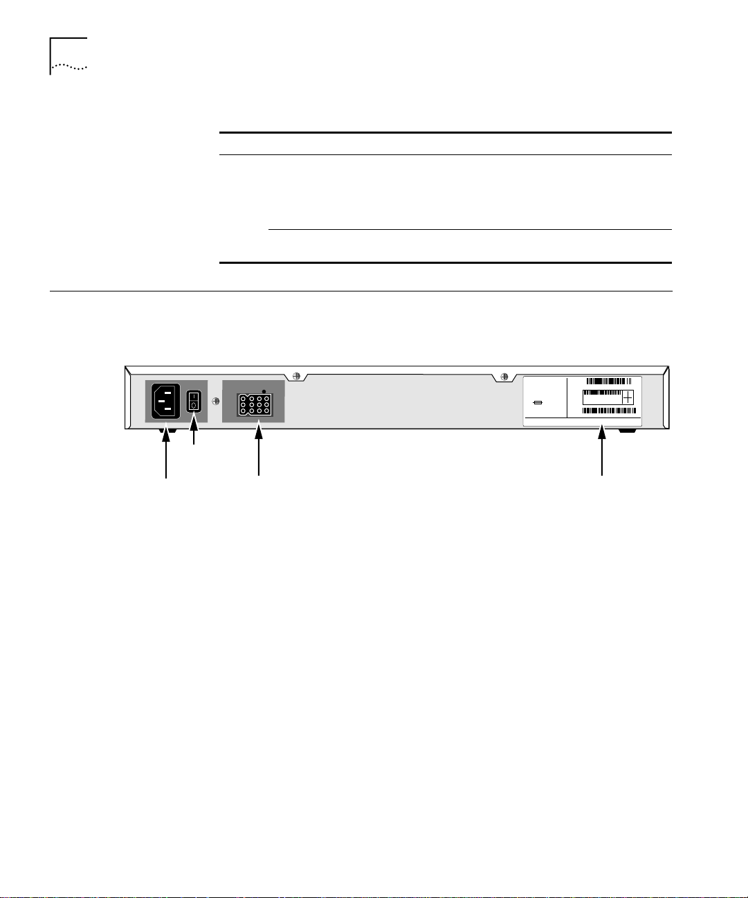
Back and Front Panels
Power
receptacle
Figure 1 shows the back panel of the SuperStack II bridge/router.
Figure 1 Back Panel
MODEL: xxxxxxx
S/N:
NETBUILDER
xxxxxx
xxx
NTWK
100-240VAC, 50/60HZ, 1.0-0.5A
ADDR:
250V, F2A
FOR CONTINUED PROTECTION
AGAINST FIRE HAZARD
REPLACE FUSE ONY WITH
SAME TYPE AND RATING
SANTA CLARA, CA. MADE IN USA
3COM CORP.
On/off
switch
RPS
connector
information label
Figure 2 shows the front panel of the model 4xx bridge/router and the
model 5xx bridge/router.
1SC05427
080002 04BA1E LAN
04BA1F
WAN-A
04BA20
WAN-B
04BA21
WAN-C
07/31/95
Product
8.3
20-0261-000
Page 19
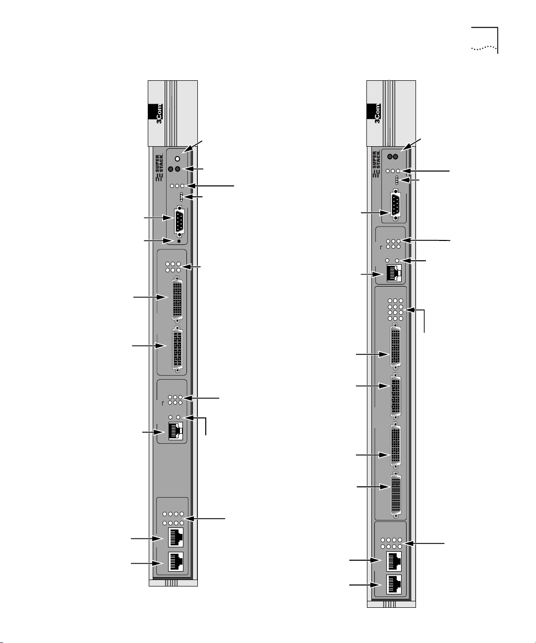
Figure 2 Models 4xx and 5xx Chassis Front Panel
Back and Front Panels 19
Console
connectors
SERIAL Flex-WAN
Model 4xx
connector
Reset
button
(A and B)
®
Aux
NETBuilder
SuperStack II
Link
B
A
B
SERIAL
A
Run
Load
Console
Reset
Active
Status
Power/
Fault
Fwd
Test
SYSTEM
Fault
Power/
Fault LED
Fwd
LEDs
Aux and
Run, Load,
Status
LEDs
Fault LEDs
and Test LEDs
(A and B)
Link, Active, and
Console
connector
WAN
connector
Model 5xx
®
Fwd
Run
NETBuilder
SuperStack II
Console
Link
B2
B1
Line
WAN
(CSU/DSU)
D
C
B
A
D
Power/
Fwd and
Fault LED
Power
/Fault
Load
Test
Status
SYSTEM
Status
Conn
Fault
Act
Line
Error
Link
Active
Fault
Run, Load,
and Test LEDs
LEDs
Link, Connect,
and Fault LEDs
Line Act and
B1 and B2)
(CSU/DSU
Line Error LEDs
Ethernet
L1 and L2
connectors
Connect
Fault
Link
B2
B1
Line
Error
Line
Act
WAN
(CSU/DSU)
WAN connector
100mb
Link
Fault
Active
L2
L1
L2
LAN
L1
Link, Connect,
and Fault LEDs
(CSU/DSU B1 and B2)
Line Act and
Line Error LEDs
100mb, Link, Active,
and Fault LEDs
(L1 and L2)
C
SERIAL
(A, B, C, and D)
B
SERIAL Flex-WAN connectors
A
100Mb
Link
Fault
Active
L2
L1
L2
LAN
Ethernet
L1 and L2
connectors
L1
Fault LEDs
(A, B, C, and D)
Link, Active, and
100Mb, Link, Active,
and Fault LEDs
(L1 and L2)
Page 20
20 CHAPTER 1: FEATURES AND SPECIFICATIONS
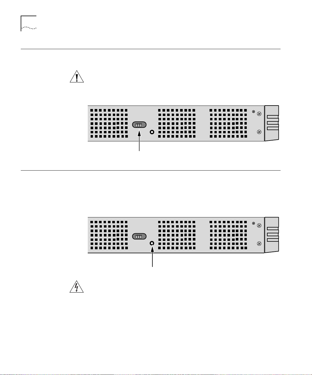
DIP Switches DIP switches are located on the left side of the bridge/router (when facing
the front panel) and are for 3Com use only.
CAUTION: To avoid accidentally erasing your flash memory or
reinitializing the EEPROM, make sure all switches are in the down
position.
Left side of unit
DIP switches
Hardware Interrupt Switch
The hardware interrupt switch is located on the left side of the
bridge/router (when facing the front panel). It is r ecessed into an opening
near the DIP switches. Press the switch with a nonconductive object, such
as a plastic stylus, to activate the monitor firmware utility.
Left side of unit
Hardware interrupt switch
WARNING: Use only a nonconductive object, such as a plastic stylus, to
press the hardware interrupt switch. Do not use the tip of a pencil.
Graphite particles from the pencil may cause you to receive an electric
shock and may damage components on the motherboard.
Page 21
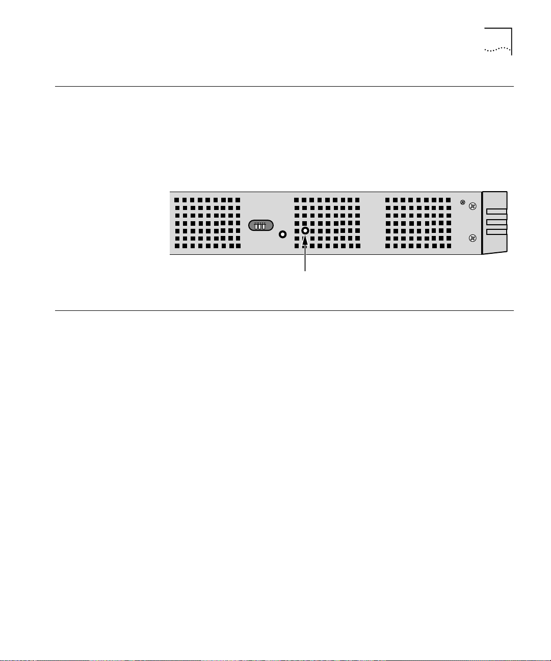
Reset Button 21
Reset Button Pressing the Reset button resets the bridge/router. The reset button on
the model 4xx bridge/router is on the front panel as shown in Figure 2.
The reset button on the model 5xx bridge/router is on the left side of the
bridge/router (when facing the front panel) as shown in Figure 3.
Figure 3 Reset Switch (Model 5xx)
Left side of unit
Reset switch
Serial Device Requirements
Serial devices using the V.25bis command set over a SuperStack II
bridge/router must support:
■ High-level data link control (HDLC) with NRZ.
■ CRN command.
■ 8 (data bits), N (no parity), and 1 (stop bit) if a parity option is
provided.
■ V.25bis addressed mode.
■ Synchronous data and DTE connection. The SuperStack II NETBuilder
bridge/router does not support an asynchronous serial connection.
Serial devices using the DTR command set over a SuperStack II
bridge/router RS-232 interface must support:
■ DTR State to Dial: HIGH.
■ DTR State Hangup: Low.
■ DTR State Answer: HIGH.
■ Synch Data Xmt (synchronous data and DTE connection). The
SuperStack II NETBuilder bridge/router does not support an
asynchronous serial connection.
■ Auto Answer mode.
■ User-stored phone number.
Page 22

22 CHAPTER 1: FEATURES AND SPECIFICATIONS
Page 23
USING THE BRIDGE/ROUTER IN
2
Overview SuperStack II bridge/routers maintain connectivity among small, midsize,
Y
OUR NETWORK
This chapter gives an overview of SuperStack II NETBuilder SI
bridge/routers and describes how they fit in your network. It also
describes the software features of the bridge/router.
and large branch offices and the corporate LAN.
SuperStack II NETBuilder SI bridge/routers come with two Ethernet ports,
two or four serial ports, and one of the following WAN ports: ISDN S/T
(models 43x and model 53x), ISDN U (models 44x and 54x), 56/64 Kbps
Carrier Service Unit/Data Service Unit (CSU/DSU) (models 45x and 55x), or
T1/FT1 Telco port (models 46x and 56x). You can change any model 4xx
bridge/router to another model 4xx, or any model 5xx to another model
5xx, by installing, removing, or replacing an interface module.
All models can be upgraded to any software package. All models have
dual-image software support for upgrading and backup.
Using Ethernet LAN Ports
The SuperStack II NETBuilder SI bridge/router provides connection to two
Ethernet LANs using either 10BASE-T or 100BASE-TX Ethernet. Boundary
router models have one port disabled. If you upgrade to full router
software, the second port will be functional.
Leaf node Boundary Routing
bridge/routers.
®
is not available on the model 5xx
Page 24

24 CHAPTER 2: USING THE BRIDGE/ROUTER IN YOUR NETWORK
Using WAN and Serial Ports
ISDN Port (Model 43x,
53x, 44x and 54x)
SuperStack II NETBuilder SI bridge/routers come with two or four serial
ports and one of the following WAN ports: a built-in ISDN S/T terminal
adapter (TA) (models 43x and 53x), a built-in ISDN U TA (models 44x and
54x), a built-in 56/64 Kbps CSU/DSU (models 45x and 55x) or a built-in
T1/FT1 Telco port (models 46x and 56x).
The ISDN port provides a basic rate interface (BRI). The BRI delivers two
bearer (B) channels and one delta (D) channel. Each B channel can
transmit up to 64 kilobits per second (kbps); the D channel transmits
information about the call to computers at the switching system at a rate
of 16 kbps. You can use both B channels together for a combined data
rate of 128 kbps, or use each 64 kbps B channel separately.
Some ISDN lines support up to 56 Kbps per B channel. For more
information, contact your ISDN service provider.
Order ISDN lines from the phone company. See Appendix E for more
information about ordering ISDN lines.
Installations in Hong Kong should be configured to originate and receive
ISDN calls at 64 Kbps. Due to the variety of ISDN switches in the Hong
Kong Telcom network, the SuperStack II NETBuilder SI bridge/router does
not handle rate adapted ISDN calls at 56 Kbps properly.
56/64K CSU/DSU Port
(Model 45x
and 55x)
T1/FT1 CSU/DSU Port
(Model 46x and 56x)
A CSU/DSU is equivalent to a modem for a digital line. The 56/64K
CSU/DSU port connects directly to a Digital Data Service (DDS).
Order DDS lines from the phone company. Contact your phone company
for more information about DDS lines and the services available for them.
A CSU/DSU is equivalent to a modem for a digital line. The T1/FT1
CSU/DSU port connects directly to a T1 line or a fractional T1 line.
Fractional T1 consists of 24 channels (DS0s) at 64 Kbps each, so you can
connect to one or more DS0s with the T1/FT1 port.
Order T1 lines from the phone company. Contact your phone company
for more information about T1 lines and the services available for them.
Page 25

Telco Services 25
Serial Ports The serial ports are multifunction Flex-W AN ports that provide connection
to industry-standard V.35, RS-232, RS-449, RS-530, or X.21 Data
Communications Equipment (DCE) or Data Terminal Equipment (DTE)
serial devices. You can buy Flex-WAN cables separately from 3Com. See
Appendix D for more information about Flex-WAN cables.
If you are using two SuperStack II NETBuilder SI bridge/routers connected
directly to each other by the serial ports (back-to-back), the
bridge/routers do not meet radiated emissions specifications.
For boundary routers, only one serial or WAN port can be active. The
remaining ports are used for back-up only.
Telco Services To create a WAN, you must buy lines and services from a
telecommunications company (Telco). Services include dial-up lines,
leased lines, and packet-switched services.
Dial-up lines, like ISDN, allow you to dial your destination when necessary
and hang up when you no longer need the connection. A leased line is
always available between two locations. Dial-up and leased lines both use
the Point-to-Point Protocol (PPP).
Packet-switched services, like Frame Relay, use a combination of leased or
dial-up lines with Telco-owned switching, which frees you from the cost
of owning the line the entire length.
Table 4 describes dial-up and leased line services available for the WAN
and serial ports. Table 5 describes packet-switched services.
Table 4 Dial-Up and Leased Line Services
Serial Device (Required
Telco Line Protocol
Dial-Up Lines:
Plain Old Telephone
Service (POTS)
ISDN BRI PPP TA 2 channels up to 64 Kbps each
Switched 56 PPP CSU/DSU 56 Kbps
Leased Lines:
E1 PPP CSU/DSU 2.048 Mbps
T1 PPP CSU/DSU 1.544 Mbps
PPP Modem Up to 56 Kbps
on Flex-WAN Serial Ports)
Data Transfer Rate
*
Page 26

26 CHAPTER 2: USING THE BRIDGE/ROUTER IN YOUR NETWORK
Table 4 Dial-Up and Leased Line Services
Serial Device (Required
Telco Line Protocol
Fractional T1 PPP CSU/DSU Up to 24 channels (DS0s) at 64
Digital Data Service (DDS) PPP CSU/DSU Up to 64 Kbps
*Some ISDN lines support up to 56 Kbps per B channel. For more information, contact your ISDN service provider.
Table 5 Packet-Switched Services
on Flex-WAN Serial Ports)
Data Transfer Rate
Kbps each
Packet-Switched
Services/Protocol
X.25 POTS Modem Up to 56 Kbps
Frame Relay Leased line CSU/DSU Up to 2.048 Mbps
SMDS Leased line CSU/DSU Up to 2.048 Mbps
Telco Line
Serial Device (Required on
Flex-WAN Serial Ports)
Data Transfer Rate
Using PPP on Dial-Up and Leased Lines
All dial-up and leased lines use PPP. If you want to use multiple lines or
channels to connect to the same destination, you can use Multilink PPP.
Multilink PPP is especially useful for ISDN, as described in the following
section.
ISDN ISDN consists of two bearer (B) channels and one delta (D)
channel. Each B channel can transmit up to 64 Kbps; the D channel
transmits signaling information about the call to computers at the
switching system at a rate of 16 Kbps.
With Multilink PPP, you can use both B channels together for a combined
data rate of 128 Kbps. With PPP, you can use each 64 Kbps B channel
separately.
Some ISDN lines support up to 56 Kbps per B channel. For more
information, contact your ISDN service provider.
Using Packet-Switched Network Services
You can use packet-switched services with your bridge/router instead of
dial-up or leased lines to take advantage of high performance for a
reasonable price. This section describes X.25 and Frame Relay.
X.25 An X.25 packet-switched network is defined by the International
Telecommunications Union (ITU) Recommendation X.25, a global
standard that began development in the 1970s. The recommendation
Page 27

Telco Services 27
defines a point-to-point interaction between DTEs and DCEs. In simpler
terms, when it is time to transmit data, a terminal connects to a modem
or packet switch, which then connects to packet switching exchanges
(PSEs) and other DCEs to transmit the data to its final destination at
another terminal. The links by which data is transmitted are called virtual
circuits. Virtual circuits allow data transfers between two points on the
network through any number of nodes in the network.
Frame Relay Frame Relay provides a packet-switched network that
transfers data between DTEs, which can be routers, bridges, and host
computers, by creating virtual circuits and using DCEs to transfer the data
to its destination.
Frame Relay differs from X.25 (which was developed to work over
voice-grade telephone lines) because it was designed to make use of
today’s higher speed digital lines. Frame Relay has also been designed to
work within complex internetworking environments with extensions
referred to as the local management interface (LMI).
LMI provides information about all devices that are accessible on the
Frame Relay network by listing all data link connection identifiers (DLCIs)
connecting the local system with the remote ones. The LMI improves
reliability between the DTE and DCE through frequent exchange of
keepalive packets that contain status information.
IBM Legacy Networks Each serial port can be attached directly with a Flex-WAN cable to IBM
legacy equipment like mainframes and automatic teller machines. See
Table 4 for supported IBM protocols.
Page 28

28 CHAPTER 2: USING THE BRIDGE/ROUTER IN YOUR NETWORK
Page 29

3
INSTALLING THE HARDWARE
This chapter describes how to install your SuperStack II NETBuilder SI
bridge/router.
Required Equipment
Table 6 lists the items you receive in the shipping carton and items you
need to provide.
Table 6 Equipment Received and Equipment Needed
Shipping carton contents ■ SuperStack II NETBuilder SI bridge/router
■ Power cable
■ Models 44x and 54x: ISDN U cable
■ Models 45x, 55x, 46x and 56x: CSU/DSU loopback plug
■ Rack-mount kit
■ Models 46x and 56x: RJ-48 T1 cable
■ Software CD-ROM
■ Documentation and documentation CD-ROM
What you need to provide ■ Synchronous serial devices like a channel service unit/digital service unit
(CSU/DSU), modem, or ISDN TA.
■ NT1 for models 43x and 53x in the U.S. and Canada
■ Interface module (available from 3Com — optional)
■ 10BASE-T or 100BASE-TX network cables
■ Flex-WAN cables (available from 3Com). See “Serial Connectors and Flex-WAN
Cables” on page 174 for more information about ordering Flex-WAN cables.
■ Models 43x and 53x: ISDN S/T cable
■ Models 45x and 55x: CSU/DSU cable
■ Terminal, PC, or modem and cable
*The software is preinstalled in the flash memory drive of the bridge/router and automatically loads when you turn on the power.
The software CD-ROM is for software recovery purposes only.
*
(except for boundary router models)
WARNING: To eliminate cable noise emission in excess of FCC
regulations, part 15, subpart J, and EN55022B, all interconnection cables
should be equipped with shielded connectors, the backshells of which
must completely surround the cable shield.
Page 30

30 CHAPTER 3: INSTALLING THE HARDWARE
For more information on cables, see Appendix D.
Environmental Requirements
Table 7 provides the environmental requirements of the SuperStack II
bridge/routers.
Table 7 Environmental Requirements
Parameter Minimum Requirement Maximum Requirement
Temperature
Operating 5 °C 40 °C
Nonoperating -40 °C 75 °C
Altitude
Operating 15,000 ft 15,000 ft
Nonoperating 40,000 ft 40,000 ft
Relative Humidity
Operating 10% noncondensing 90% noncondensing
Nonoperating 10% noncondensing 90% noncondensing
Page 31

Mounting the Bridge/Router 31
Mounting the Bridge/Router
Mounting Kit The mounting kit contains the following hardware:
You can mount your bridge/router on a tabletop, stack several with
brackets, or mount the bridge/router in a rack.
Figure 4 Mounting Kit Contents
Two brackets
Four adhesive-backed
rubber feet
Four 8-32 Phillips
flathead screws for use
when stacking bridge/routers
Installing on a
Tabletop
If you plan to install your
bridge/router on a tabletop, attach
the rubber feet as shown.
Attach feet to corners
of chassis bottom
Flex plastic sheet until
feet pop loose
Page 32

32 CHAPTER 3: INSTALLING THE HARDWARE
Stacking with
Brackets
See Figure 5 to securely stack several bridge/routers on a tabletop.
CAUTION: Do not restrict air flow around the sides and back of the
bridge/router.
Figure 5 Stacking Bridge/Routers
Attach brackets as shown
to lock two units together
Place screws in holes as shown
Bottom bracket acts as a support
Page 33

Mounting the Bridge/Router 33
Installing in a Rack To install the bridge/router in a rack, follow these steps:
CAUTION: Do not restrict air flow around the sides and back of the
bridge/router.
1 Secure the rack-mount brackets to each side of the chassis using two
flathead screws per bracket.
2 Hold the chassis between the poles of the rack and attach the brackets to
the rack using panhead screws (you must provide these screws). Tighten
each screw securely.
CAUTION: Using fewer than two screws to secure the brackets to the
rack may cause the boundary router to fall and sustain damage not
covered by the warranty.
Page 34

34 CHAPTER 3: INSTALLING THE HARDWARE
Cabling the Connectors
Cabling the LAN
Connectors
The SuperStack II NETBuilder SI bridge/router has two Ethernet ports,
either two or four serial ports depending on the model, and one of the
following WAN ports: ISDN S/T (43x and 53x), ISDN U (44x and 54x),
56/64 Kbps CSU/DSU (45x and 55x), or T1/FT1 CSU/DSU (46x and 56x).
This section describes how to cable each port on your bridge/router.
Boundary router models can use only one Ethernet port and only one
serial or WAN port can be active at a time. You can cable the remaining
serial or WAN ports to be used as back-up. If you upgrade to full router
software, the second Ethernet port and back-up serial ports will be
functional.
You can cable one or two Ethernet connectors using either 10BASE-T or
100BASE-TX cabling. If you have a boundary router, cable only the L1
connector.
LAN
L1
L1L2L2
100mb
Link
Active
Fault
10BASE-T or 100BASE-TX cables
For more information about Ethernet connectors and cables, see “LAN
Connector and Cables” on page 165.
Page 35

Cabling the Connectors 35
Cabling the WAN
Connector
This section describes the WAN connector for each bridge/router model.
Model 43x and 53x ISDN S/T
Models 43x and 53x bridge/routers have an ISDN S/T connector.
WAN
(CSU/DSU)
B2
B1
Line
Link
Act
Connect
Line
Error
Fault
ISDN-U BRI
Wall outlet
ISDN S/T cable
Network
termination
(NT1)/power
supply*
S/T interface
*required for U.S.
and Canada only
U interface
The ISDN S/T port uses an RJ-45 connector. In the U.S. and Canada,
purchase an NT1 from an ISDN equipment vendor, and use it between
the bridge/router and the ISDN outlet. In other countries, you do not
need to provide an NT1 because the function is provided by the ISDN
equipment at the customer site.
For more information on ISDN cables, see “ISDN S/T Cable” on page 170.
Model 44x and 54x ISDN U
Models 44x and 54x bridge/routers have an ISDN U connector.
WAN
(CSU/DSU)
B1
B2
Line
Link
Act
Connect
ISDN U cable
Line
Fault
Error
ISDN-U BRI
wall outlet
Page 36

36 CHAPTER 3: INSTALLING THE HARDWARE
The ISDN U port uses an RJ-45 connector. In the U.S. and Canada, you do
not need a separate NT1 between the bridge/router and the ISDN outlet
because the NT1 is built into the model 44x bridge/router.
For more information on ISDN cables, see “ISDN S/T Cable” on page 170.
Model 45x and 54x 56/64K CSU/DSU
Models 45x and 55x bridge/routers have a 56/64K CSU/DSU connector.
56/64 Kbps
CSU/DSU cable
The 56/64K CSU/DSU port uses an RJ-48S connector.
WAN
(CSU/DSU)
Act
Line
Error
B1 B2
LinkLine
Connect
Fault
DDS
wall outlet
For more information on CSU/DSU cables, see “56/64K CSU/DSU Cable”
on page 173.
Model 46x and 56x T1/FT1
Models 46x and 56x bridge/routers have a T1/FT1 RJ-48 connector.
WAN
(CSU/DSU)
B1 B2
LinkLine
Act
Connect
Line
Fault
Error
wall outlet
RJ-48 T1 cable
The T1/FT1 Telco port uses an RJ-48 connector.
Page 37

Cabling the Connectors 37
Cabling the Serial
Connectors
Flex-WAN cables
The SuperStack II bridge/router has either two or four Flex-WAN serial
connectors depending on the model. Order the appropriate Flex-WAN
cable from 3Com for your serial device. See “Serial Connectors and
Flex-WAN Cables” on page 174 for more information about the
Flex-WAN cables.
Model 4xx
SERIAL
A
Model 5xx
B
B
A
Link
Active
Fault
Connect to RS-232, RS-449,
V.35 or X.21 DTE or DCE
or RS-530 DCE
Flex-WAN cables
SERIAL
D
C
A
A
B
C
D
B
Link
Active
Fault
Connect to RS-232, RS-449,
V.35 or X.21 DTE or DCE
or RS-530 DCE
Page 38

38 CHAPTER 3: INSTALLING THE HARDWARE
Attaching a Redundant Power System
Wall outlet
You can attach your SuperStack II bridge/router to a SuperStack II
Redundant Power System (RPS).
SuperStack II bridge/router
SuperStack II Redundant Power System
Power cable
RPS cable
Power cable
For full power supply redundancy, attach one end of the RPS cable to the
rear panel on the bridge/router and the other end to the RPS. Then attach
one end of the power cord to the rear panel on the bridge/r outer and the
other end to a power outlet.
In this configuration, the internal supply provides power. If the internal
supply fails or is switched off, or if there is a power failure, the RPS is
activated and the bridge/router reboots.
To reset a bridge/router in this configuration, turn the power off, wait 5
seconds and turn it back on. The bridge/router switches to the RPS, then
switches back to the internal supply to reboot.
CAUTION: For system susceptibility protection, always leave the AC cord
attached to the bridge/router and to a power outlet.
Internal power supply failure is rare. If it occurs, the power switch on your
bridge/router will not operate. To reboot, unplug the RPS cable and then
plug it back in. Replace your bridge/router with another bridge/router
that has a functioning internal power supply as soon as possible. Contact
your 3Com representative to replace your bridge/router.
Page 39

Connecting a PC, Terminal, or Modem 39
Connecting a PC, Terminal, or Modem
Connect a PC running a terminal emulation program, a terminal, or a
modem to the console port on the SuperStack II bridge/router to
configure the bridge/router software and review startup and system
operation messages.
To connect a PC, terminal, or modem to the bridge/router, follow
these steps:
1 Obtain a cable to connect the device to the console port on the
bridge/router. See “Console Connector and Cables” on page 163 for
cable pinouts.
The console port is a 9-pin male connector.
For the PC, use a 9-pin female to 9-pin female null modem-type cable.
For the terminal, use a 9-pin female to 25-pin null modem-type cable.
For the modem, use a 9-pin female to 25-pin male straight-through-type
cable.
2 Connect one end of the cable to the console port on the SuperStack II
system and the other end to the serial port on the back of your device.
3 Verify that configurable parameters of your device match the
configuration settings of the console port specified in Table 8.
Table 8 Console Port Configuration Settings
Characteristic Setting
Baud rate 9600
Databits 8
Parity None
Stop bits 1
DTR Ignored
Duplex Full
Echo Off
Flow control X-on/X-off
4 Turn on the device.
Shutting Down If your SuperStack II system is not connected to an RPS, turn off the
power by pressing the off (0) side of the power switch on the back panel.
If your system is connected to an RPS, turn off the power by unplugging
the RPS cable from the system and then pressing the off (0) side of the
power switch.
Page 40

40 CHAPTER 3: INSTALLING THE HARDWARE
Page 41

INSTALLING OR REMOVING AN
4
I
NTERFACE MODULE
This chapter describes how to install or remove interface modules in
SuperStack II NETBuilder SI bridge/routers.
The following table lists each model number and the interface module it
contains.
Model Module Installed
43x/53x ISDN S/T port with no interface module
44x/54x ISDN U interface module
45x/55x 56/64 Kbps CSU/DSU module
46x/56x T1/FT1 CSU/DSU module
You can change any model 4xx bridge/router to another model 4xx, or
any model 5xx bridge/router to another model 5xx bridge/router by
installing, removing, or replacing the interface module.
Removing the Cover
To remove the cover, follow these steps:
1 Remove the power cord and all cables from the chassis.
2 If the bridge/r outer is mounted with brackets, unmount it and r emove the
brackets.
3 Remove the two screws from the back of the chassis.
Remove screws
MODEL: xxxxxxx
S/N:
NETBUILDER
xxxxxx
xxx
100-240VAC, 50/60HZ, 1.0-0.5A
FOR CONTINUED PROTECTION
AGAINST FIRE HAZARD
REPLACE FUSE ONY WITH
SAME TYPE AND RATING
3COM CORP.
250V, F2A
1SC05427
080002 04BA1E LAN
07/31/95
8.3
04BA1F
WAN-A
04BA20
WAN-B
04BA21
WAN-C
20-0261-000
NTWK
ADDR:
SANTA CLARA, CA. MADE IN USA
Page 42

42 CHAPTER 4: INSTALLING OR REMOVING AN INTERFACE MODULE
4 Remove the cover.
With the front panel facing you, push down on cover with both hands
Slide cover back slightly
Lift cover away from chassis
Page 43

Removing an Existing Module (Model 4xx) 43
Removing an Existing Module (Model 4xx)
To remove an existing module from a model 4xx bridge/router, follow
these steps:
1 Remove the screw from the standoff.
Rear panel
Front panel
Remove screw
2 Remove the module.
Front panel
Lift module straight up off the connectors
Page 44

44 CHAPTER 4: INSTALLING OR REMOVING AN INTERFACE MODULE
3 If you are not installing another module, change the jumper to the
left-hand set of pins and reinstall the screw on the standoff.
Front panel
Move the jumper to the
left-hand set of pins
4 Reinstall the cover and the cover screws.
CAUTION: The DIP switches should all be in the down position. The DIP
switches are accessible through an opening on the side of the chassis.
Install screws
DIP switches should all
be in the down position
5 If the bridge/r outer was mounted with brackets, r einstall the brackets and
remount it.
6 Reconnect the power cord and all cables.
Page 45

Installing a New Module (Model 4xx) 45
Installing a New Module (Model 4xx)
To install a new module in a model 4xx bridge/router, follow these steps:
1 Remove the screw from the standoff if necessary.
Front panel
Remove screw
2 Move the jumper to the right-hand set of pins.
Front panel
Move the jumper to the
right-hand set of pins
Page 46

46 CHAPTER 4: INSTALLING OR REMOVING AN INTERFACE MODULE
3 Insert the new module.
Front panel
Connectors
Install module by matching connectors
Connectors
(on underside
of module)
4 Reinstall the screw on the standoff.
5 Reinstall the cover and the cover screws.
CAUTION: The DIP switches should all be in the down position. The DIP
switches are accessible through an opening on the side of the chassis.
Install screws
DIP switches should all
be in the down position
6 If the bridge/r outer was mounted with brackets, r einstall the brackets and
remount it.
7 Reconnect the power cord and all cables.
Page 47

Removing an Existing Module (Model 5xx) 47
Removing an Existing Module (Model 5xx)
To remove an existing module from a model 5xx bridge/router, follow
these steps:
1 Remove the screw from the standoff.
Rear panel
Front panel
Remove screw
2 Remove the module.
Front panel
Lift module straight up off the connectors
Page 48

48 CHAPTER 4: INSTALLING OR REMOVING AN INTERFACE MODULE
3 If you are not installing another module, change the jumper to the
left-hand set of pins and reinstall the screw on the standoff.
Front panel
Move the jumper to the
left-hand set of pins
4 Reinstall the cover and the cover screws.
CAUTION: The DIP switches should all be in the down position. The DIP
switches are accessible through an opening on the side of the chassis.
Install screws
DIP switches should all
be in the down position
5 If the bridge/r outer was mounted with brackets, r einstall the brackets and
remount it.
6 Reconnect the power cord and all cables.
Page 49

Installing a New Module (Model 5xx) 49
Installing a New Module (Model 5xx)
To install a new module in a model 5xx bridge/router, follow these
steps:
1 Remove the screw from the standoff if necessary.
Rear panel
Front panel
Remove screw
Page 50

50 CHAPTER 4: INSTALLING OR REMOVING AN INTERFACE MODULE
2 Move the jumper to the right-hand set of pins.
Front panel
3 Insert the new module.
Front panel
Install module by matching connectors
Move the jumper to the
right-hand set of pins
Connectors
Connectors
(on underside
of module)
Page 51

Installing a New Module (Model 5xx) 51
4 Reinstall the screw on the standoff.
5 Reinstall the cover and the cover screws.
CAUTION: The DIP switches should all be in the down position. The
DIP switches are accessible through an opening on the side of the
chassis.
Install screws
DIP switches should all
be in the down position
6 If the bridge/router was mounted with brackets, reinstall the brackets
and remount it.
7 Reconnect the power cord and all cables.
Page 52

52 CHAPTER 4: INSTALLING OR REMOVING AN INTERFACE MODULE
Page 53

LOGGING ON AND PERFORMING
5
A
DMINISTRATIVE TASKS
This chapter describes how to start up the system, log on, use the user
interface, and perform basic administrative tasks that you must complete
before configuring the ports and paths and bridging or routing protocols
that you plan to run on your bridge/router.
Table 9 summarizes the administrative tasks described in this chapter and
indicates whether performing each task is required, recommended, or
optional.
Table 9 Administrative Task Summary
Task Status of Task
Changing the Root Password Required
Changing the Default Console Port Baud
Rate
Adding User Accounts Optional
Setting the Time and Date Recommended
Setting System Information Required
Setting Up Security Recommended
Do only if you want to attach a terminal
with a baud rate other than 9600.
Turning on the System
For more information on each of the commands and parameters used in
this section, see Reference for Enterprise OS Software.
To start up your bridge/router, plug one end of the power cord into the
rear panel of the bridge/router and the other end into your power outlet.
In addition, if you have a SuperStack II Redundant Power System (RPS),
attach one end of the RPS cable to the rear panel of the bridge/router and
the other end to the RPS.
Page 54

54 CHAPTER 5: LOGGING ON AND PERFORMING ADMINISTRATIVE TASKS
Verifying Successful
Startup
The startup process takes a few minutes. When the startup process has
successfully completed, the LEDs on the front panel should be on or off
as described in Table 10.
If the LEDs on your bridge/router appear different from those shown in
Table 10, the bridge/router may have a problem. See Appendix A for
more information.
Table 10 LED Status at Successful Startup
LED Status
LAN
Link On
Active On
Fault Off
WAN
Line Act On
Line Error Off
Link On
Connect On
Fault Off
SERIAL
Link On
Active On
Fault Off
SYSTEM
Status All off
Fwd Off or blinking
Power/Fault Green
Run On
Load Off
Test Off
AUX Off
If the bridge/router is configured for an ETSI switch and there are no ISDN
B channel connections, the ISDN Line Act LED is off. If a B channel is not
connected, the Link and Connect LEDs are also off. The LED configuration
shown in this figure occurs when all channels are connected.
Page 55

Attaching a Console 55
Attaching a Console You must attach a console to the bridge/router for initial software
configuration. For information about attaching a PC, terminal, or
modem, see the hardware installation guide for the bridge/router.
After you have configured the software, you can access the user interface
using one of the following methods:
■ Telnet to the bridge/router from a device (for example, a workstation)
on the same extended network or internetwork.
The software supports Transmission Control Protocol (TCP) and User
Datagram Protocol (UDP). These protocols allow you to Telnet to the
bridge/router using an Internet Protocol (IP) address. For more
information about using Telnet on a workstation, see the manual that
came with your Telnet application.
■ Use Simple Network Management Protocol (SNMP) to view and
configure a subset of the parameters from a remote host. For
information on preparing the bridge/router to run SNMP, see Using
Enterprise OS Software.
Logging on to
the System
When your bridge/router starts up, it takes a few minutes to complete the
initialization process. While the bridge/router is initializing, several
messages appear on your terminal. The bridge/router has finished
booting when the following message is displayed:
System Initialized and Running
To log on, follow these steps:
1 Press any key on the keyboard.
The following prompt is displayed:
NetLogin:
2 Enter:
root
Root is the default account name. The following prompt is displayed:
Password:
3 Press the Return key.
Pressing the Return key enters a null string, which is the default local
password. The Network Manager prompt is displayed:
Enterprise OS
#
Page 56

56 CHAPTER 5: LOGGING ON AND PERFORMING ADMINISTRATIVE TASKS
Choosing the User Interface
Deciding which
Interface to Use
Using Menus The MEnu command allows you to:
This section describes how to access the menu-driven and command-line
user interfaces. Detailed information for both types of interfaces is
provided so that you can choose the one that best suits your needs.
After you have accessed the user interface, you need to decide whether
to use the menu-driven or the command-line interface.
■ If you are unsure of the command syntax, use the menu-driven
interface.
For more information about the MEnu command, see Reference for
Enterprise OS Software. For information on how to use the
menu-driven interface, see the next section.
■ If you know the exact syntax, enter the command at the system
prompt.
For information about the command line and rules for entering
commands, see Appendix C. To access the command-line, see “Using
the Command-line Interface” on page 57. The syntax for each
command and parameter is described in Reference for Enterprise OS
Software.
■ Display a list of available services.
■ Choose a service and display the list of parameters available for
that service.
■ Display a list of parameters in the current service.
■ Choose a parameter and display the commands used with it.
■ Check the active and default values of a parameter.
■ Display the online help syntax of a parameter.
■ Enter the new value of a parameter.
The following prerequisites and notes apply when using the menu-driven
interface:
■ You must have Network Manager privilege.
■ You cannot access some parameters; for example, you cannot alter
the number of lines on the screen, or change privilege level.
■ To access the SuperStack II system thr ough the REMote command, you
must use the command-line interface.
Page 57

Choosing the User Interface 57
To use the menu-driven interface, follow these steps:
1 Log on as r oot or as a user with Network Manager privilege (see “Adding
User Accounts” on page 60 for more information about user accounts).
2 If you have not selected a particular service, enter:
MEnu
The Main menu display appears.
3 Select the desired service.
For example, selecting 1 from the Main menu display generates a menu
for the SYS Service.
4 Select the parameter you want to configure.
For example, if you selected 27 from the SYS Service menu, a display
appears for that parameter.
The first part of the screen displays the value of the parameter. The
second part lists the commands from which you can choose. For
information on the help menus, see “Getting Help” on page 160. For the
complete rules for entering commands and using aliases and history
substitution, see “Using Aliases” on page 157 and “Command History
Substitution” on page 158.
Using the
Command-line
Interface
5 To escape out of a menu, press the Return key, which takes you to the
previous menu level.
For example, if you are at the Main menu and you press the Return key,
you will return to the command-line interface.
For information about the command line and rules for entering
commands, see Appendix C.
To use the command-line interface, follow these steps:
1 Log on as r oot or as a user with Network Manager privilege (see “Adding
User Accounts” on page 60 for more information about user accounts).
2 Type the command name. For a complete list of commands, enter a
question mark (?).
If your command does not require a service name, parameter, or values,
skip to step 3. If your command requires more modification, continue to
step a.
a If the command has additional options, such as a port or path number,
include it after the command name.
Page 58

58 CHAPTER 5: LOGGING ON AND PERFORMING ADMINISTRATIVE TASKS
When you include a specific port or path number in the command,
that command focuses on that particular port or path. If the port or
path number is not included, the command provides information on
all ports or paths.
For more information on ports, paths, or commands, see Reference
for Enterprise OS Software.
b If the command is modified by a parameter, type the service name (if
necessary), the parameter name, and values.
The service part of the command focuses the action of the command
on a particular service of the system.
In some cases, you may not need to enter the service name. For
example, if a parameter is unique to a particular service, the service
need not be specified as part of the command. For more information,
see “Entering Service Names in Command Lines” on page 157.
The parameter is the object of the action of the command. If two or
more services have parameters of the same name, you must include
the service name in the syntax so the command can be executed
successfully.
The value part of the command specifies how you want the parameter
to be set. Values include numerics, strings, or addresses depending on
the parameter.
3 Press the Return key after typing the complete command.
The software includes online help for commands, services, parameters,
and syntax, and is described in “Getting Help” on page 160. The syntax
style that appears in the online help is the full form syntax; it contains full
names and visual cues for entering commands. You can also enter
commands using an abbreviated version of the syntax style.
For more information on syntax, see Appendix C.
Page 59

Changing the Root Password 59
Changing the Root Password
The default root password is a null string, which is generated by pressing
the Return key.
You should specify a new password immediately after you log on for the
first time. Changing the root password pr events unauthorized users fr om
accessing and executing software commands and parameters.
The root user has two privilege levels and passwords: Network Manager
and User . The User privilege enables only a subset of softwar e commands.
You should assign passwords for both levels. If you log in as root and
enter the Network Manager password, you have Network Manager
privilege. If you log in as root with the User password, you have User
privilege.
You might log on with the User password if you do not want to create
user accounts. If you want to change the privilege level without logging
off, use:
SET -SYS PRIvilege = User | NetMgr
The following guidelines exist when changing a password:
■ You must be logged on as root with Network Manager privilege.
■ You must change the Network Manager passwor d befor e you change
the User password.
■ You must clear the User password before you clear the Network
Manager password.
To change the password for both privilege levels, enter:
SysPassWord
A menu is displayed.
Follow the menu to set the Network Manager password and then the
User password.
CAUTION: You must set both the Network Manager and the User
password. If the User password is not set, any unauthorized user can
logon with User level privilege.
Page 60

60 CHAPTER 5: LOGGING ON AND PERFORMING ADMINISTRATIVE TASKS
Changing the Default Console Port Baud Rate
To attach a terminal with a baud rate other than 9600, follow
these steps:
1 At the Network Manager prompt (Enterprise OS #), enter:
SysconF
The System Configuration menu is displayed.
2 Select the Console Port option.
A submenu displays the console port baud rate options.
3 Select the baud rate you want to use.
4 Set the terminal baud rate to match the baud rate configured for the
console port.
CAUTION: Do not reset the bridge/router before changing the terminal
baud rate. After the bridge/router resets, the new baud rate is used and
you will not be able to access the system software to enter any
commands at the default 9600 baud rate.
5 After you change the terminal baud rate, reset the bridge/router.
The new console port baud rate does not become effective until you have
reset the bridge/router.
Adding User Accounts
You can add user accounts with either Network Manager or User
privilege. Some commands are available only to root.
To add a user account, log on as root and use:
AddUser [<username>]
If you do not specify a username, you will be prompted for one. Specify
the privilege and password at the prompts.
Delete an account using:
DELeteUser [<username>]
To force a user password to expire, use:
EXPire [<username>]
Any user can change their password by entering:
PassWord
Page 61

Setting the Time and Date 61
To manage multiple users and see all user accounts, enter:
UserManage
Setting the Time and Date
Setting System Information
3Com recommends setting the time and date. Use:
SET -SYS DATE = <YYYY/MM/DD HH:MM[:ss]>
Enter the time in 24-hour-clock format. For example, to set the date and
time to January 10, 1996, 2:40 p.m., enter:
SET -SYS DATE = 1996/1/10 14:40
You should set the system name to interoperate with other NETBuilder
bridge/routers. You can also set the location and contact so that other
system administrators can contact you for information.
To set the system name, location, and contact, follow these steps:
1 (Required) Assign a name to the bridge/router using:
SETDefault -SYS SysNAMe = “<string>”
For example, to set the system name to Engineering.SanJose, enter:
SETDefault -SYS SysNAMe = “Engineering.SanJose”
2 (Optional) Specify the system location using:
SETDefault -SYS SysLOCation = “<string>”
For example, to set the system location to SecondFloor.Lab, enter:
SETDefault -SYS SysLOCation = “SecondFloor.Lab”
3 (Optional) Identify the contact person managing the bridge/router using:
SETDefault -SYS SysCONtact = “<string>”
For example, to identify John Smith as the system contact and
(408)555-1111 as the phone number at which to reach him, enter:
SETDefault -SYS SysCONtact = “John Smith (408) 555-1111”
If the system contact is specified, users can obtain this information using
the SHow -SYS SysCONtact command.
Page 62

62 CHAPTER 5: LOGGING ON AND PERFORMING ADMINISTRATIVE TASKS
Setting Up Security To allow system administrator-only access to files, use these commands
and parameters:
■ RemoteManager
This SYS Service parameter specifies the Internet addresses of devices
that can connect to the system through the REMote command. For
information on how to use the RemoteManager parameter, see
Reference for Enterprise OS Software.
■ COMmunity
This SNMP Service parameter modifies the list of communities. For
information on how to use the COMmunity parameter, see Reference
for Enterprise OS Software.
■ To implement auto startup, many NETBuilder confi guration files are by
default accessible to any SNMP-based manager with read and write
privileges. To set SNMP access to read-only for all managers, enter:
DELete -SNMP COMmunity “anycom”
ADD -SNMP COMmunity “anycom” RO
■ The Audit Log feature generates a log message on a network
management workstation that captures configuration changes and
events for monitoring bridge/routers. For more information on this
feature, see Using Enterprise OS Software.
Page 63

BASIC CONFIGURATION OF PORTS
6
Paths, Ports, and Virtual Ports
AND PATHS
This chapter contains conceptual information about ports and paths and
contains basic configuation procedures for each of the interfaces on your
SuperStack II NETBuilder SI bridge/router.
Ports and paths are the fundamental interface units on the bridge/router,
and understanding the concept of ports and paths is important. This
section defines ports and paths and explains how they are numbered.
The fundamental difference between paths and ports is that the path is
the physical interface and the port is the logical interface in the software
that is mapped to the physical path. Figure 6 illustrates the relationship
between paths and ports.
Figure 6 Relationship Between Physical Paths and Logical Ports
Physical connectors
NETBuilder bridge/router chassis
Physical path
!<path>
Physical path
!<path>
Paths and Ports A path is the physical interface that connects a bridge/r outer to a physical
network medium such as Ethernet or a serial line. Each path is associated
with a connector. If you have a built-in ISDN connector, each B channel is
assigned a separate path, for instance 3.1 and 3.2.
Logical port
!<port>
Logical port
!<port>
Page 64

64 CHAPTER 6: BASIC CONFIGURATION OF PORTS AND PATHS
A port is the logical interface used by the software to represent a
connection to a network.
By default, each path is assigned to one port. For example, all network
traffic received on physical path 1 is tr eated by the software as arriving on
logical port 1, and all traffic that the software transmits through logical
port 1 passes through physical path 1.
A path that is assigned to one port is a static path. Some configurations
require the options described in Table 11.
Table 11 Port and Path Options
Option Description
Multiple paths per
port: dynamic paths
Multiple paths per
port: static paths
Multiple ports per
path: virtual ports
A dynamic path is not assigned to any one port, but is
available in a dial pool. A dial pool enables you to dial
multiple destinations, use bandwidth-on-demand, and
failover to another line without having to reserve specific
paths for a port. A port may require multiple paths from the
dial pool.
Use multiple static paths on the same port:
■ To use both B channels together on a built-in ISDN
■ To reserve a path for disaster recovery.
■ To use a path for dial-on-demand, failover, or
A virtual port can be assigned to a path or to a SysCallerID
that represents a remote site.
connector using Multilink PPP.
bandwidth-on-demand.
Dynamic Paths Ports running PPP can use a dial pool of available paths. A dial pool
enables you to dial multiple destinations, use bandwidth-on-demand,
and failover to another line without having to reserve specific paths for a
port. A dial pool is created when you unbind a path from its port by
using:
SETDefault !<path> -PATH DialCONTrol = DYNamic
See “Configuring Bandwidth Management for PPP” on page 89 for more
information about bandwidth management features such as
dial-on-demand.
Page 65

65
Multiple Static Paths
per Port
Virtual Ports To configure multiple ports over one path, you create virtual ports. A
If you assign multiple paths to a port, the port must be running PPP.
To use both B channels together on a built-in ISDN connector, to r eserve a
path for disaster recovery, or to use another path for dial-on-demand,
failover , or bandwidth-on-demand, you can assign both paths to one port
and use Multilink PPP using:
ADD !<port> -PORT PAths <path> [,<path>...]
You may want to use static ports instead of a dial pool if you are only
dialing one destination and do not need the versatility of a dial pool.
See “Configuring Bandwidth Management for PPP” on page 89 for more
information about bandwidth management features such as
dial-on-demand.
virtual port can be assigned to a static path, or for PPP, it can be assigned
to the SysCallerID of a remote site. SysCallerID virtual ports use paths in a
dial pool and are not associated to any one path.
A virtual port functions the same way as a nonvirtual port does, that is, as
a logical interface that represents a connection to a network.
For example, if a SuperStack II bridge/router central node needs to
connect to two separate boundary routers over the same ISDN port at
different times, you can create a virtual port for each boundary router.
The virtual ports would have all the connection information for each
boundary router.
Table 12 provides information on topologies that require virtual ports and
the node on which the virtual ports should be created.
Table 12 Topologies that Require Virtual Ports
Node That Virtual Ports
Topology Virtual Ports Required?
Boundary Routing over Frame Relay or X.25 Yes. Central node
Traditional routed environment: partially meshed or
nonmeshed Frame Relay and X.25 topologies
Multidestination dialing (modem pooling) over PPP Yes, for dynamic dial-up lines. Central node
Frame Relay topology with disaster recovery
configured
Depends on bridging or routing
protocol. See “Virtual Ports over
Frame Relay and X.25” for more
information.
Yes. Nodes on both ends of serial
Should Be Created On
Any router
line running Frame Relay
Page 66

66 CHAPTER 6: BASIC CONFIGURATION OF PORTS AND PATHS
Virtual Ports over Frame Relay and X.25
Frame Relay and X.25 are peer-to-peer protocols that connect two nodes
on the network. Boundary Routing and bridging, Internet Protocol-Open
Shortest Path First (IP-OSPF), DECnet IV, VINES, and Xerox Network
Systems (XNS) require virtual ports because they do not pr ovide a method
for dealing with Frame Relay or X.25 topologies where bridge/routers ar e
not directly connected to all others (full mesh). With Boundary Routing
system architecture, when you cr eate a virtual port over a particular path,
each remote network attached to the Frame Relay or X.25 cloud is
treated as a separate network.
Internet Protocol-Routing Information Protocol (IP-RIP), Internetwork
Packet Exchange (IPX), DECnet V, and AppleT alk can operate over partially
meshed or nonmeshed Frame Relay or X.25 topologies without the use of
virtual ports.
The next-hop split horizon feature in IP-RIP, IPX, and AppleTalk RTMP
allows communication between bridge/routers that are not directly
connected to one another. To configure next-hop split horizon for these
routing protocols, you must have a list of neighbors, which can be
dynamically generated or manually configured in IP-RIP. Next-hop split
horizon is configured by adding static mappings to the address mapping
table.
You can configure dynamic neighbor learning for IPX using the CONTrol
parameter in the NRIP, SAP, and NLSP Services.
Although it is not necessary to define virtual ports on IP-RIP, IPX, or
AppleTalk routers in partially meshed or nonmeshed Frame Relay or X.25
topologies, virtual ports do provide the following additional benefits:
■ A virtual port can be defined for each configured neighbor, which
allows you to set up such features as filters and routing policies on a
per-neighbor basis.
■ Virtual ports provide easier control over your network, turning your
network into several point-to-point lines.
If you want your SuperStack II bridge/router to act as an Open System
Interconnection (OSI) router in a Frame Relay or X.25 topology, you do
not need to create virtual ports.
Page 67

67
Table 13 lists each bridging and routing protocol and the technique you
must use to deal with the lack of connectivity in partially meshed and
nonmeshed Frame Relay and X.25 topologies.
Table 13 Connectivity in Partially Meshed and Nonmeshed Topologies
Protocol Technique
Bridging Virtual port
Boundary Routing Virtual port
*
IP-RIP
IP-OSPF Virtual port
*
IPX
*
APPN
DECnet IV Virtual port
OSI/DECnet V No special configuration required
VINES Virtual port
XNS Virtual port
AppleTalk
*When configuring this protocol and another protocol that requires virtual ports over the same
path, use virtual ports.
*
Next-hop split horizon
Next-hop split horizon
No special configuration if sending APPN only over Frame Relay
Next-hop split horizon
Virtual Ports over PPP
PPP virtual ports differ from Frame Relay and X.25 virtual ports in the
following ways:
■ A PPP virtual port can potentially use any path in the dial pool.
Frame Relay and X.25 virtual ports are always associated with a
particular path.
■ PPP virtual ports operate independently and do not have a parent
port. No parent port exists because the path was unbound from its
port and placed into the dynamic dial path pool.
Frame Relay and X.25 virtual ports inherit the attributes of the path
over which they are defined.
■ PPP virtual ports can be used with dial-up related parameters.
Frame Relay and X.25 virtual ports cannot be used with dial-up related
parameters.
You can use virtual ports in a PPP environment to provide dial pooling at
the central site router. With dial pooling, a set of dynamic paths is
Page 68

68 CHAPTER 6: BASIC CONFIGURATION OF PORTS AND PATHS
unbound from their default ports and waits in the dial pool for an
incoming call. When a call is received, the dynamic path that answers is
assigned to a virtual port, which is standing by with the appropriate
configuration information for the calling network. Because not all sites
using a dial pool call the central site at the same time, it is possible to
share a small group of paths with a larger group of sites. Each site that
can potentially call into the dial pool has its own virtual port defined, so
there are usually more virtual ports configured for the dial pool than
dynamic paths assigned to it.
Parent Ports for Frame Relay and X.25
When you configure an X.25, or Frame Relay virtual port, it inherits the
attributes of the path over which it is defined. It also inherits some of the
attributes of its parent port.
For PPP dial virtual ports, no parent port exists because the path was
unbound from its port and placed into the dynamic dial path pool.
Unlike Frame Relay and X.25 virtual ports, which are always associated
with a particular path, PPP virtual ports can potentially use any path in the
dynamic dial path pool. PPP virtual ports also can be used with dial-up
related parameters.
For example, if you create a Frame Relay or X.25 virtual port
associated with a wide area port, the virtual port inherits port attributes
from the following sources:
■ Default and configured values of PORT Service parameters specified
for a wide area port, with the exception PORT Service parameters that
are not related to X.25 and Frame Relay virtual ports.
■ Default and configured values of parameters from all other services
specified for a wide area port.
To configure a virtual port, you must specify the virtual port and not the
parent port. For example, if you are using the SETDefault !<port> -BCN
CONTrol = Enabled syntax, you must specify the virtual port number
instead of the parent port number for <port>. For complete information
on the numbering convention of virtual ports, see “Path and Port
Numbering” on page 69.
Page 69

Path and Port Numbering 69
Path and Port Numbering
The following tables outline the default port and path numbering for the
SuperStack II bridge/router.
Although the WAN connector on the model 5xx bridge/router is in a
different physical location than the WAN connector on the model 4xx
bridge/router, its path numbering is the same.
Table 14 Path and Port Numbering for Model 43x , 44x, 53x, and 54x
Bridge/Routers
Path No. Connector Mapped To Port No. Mapped To
1 L1 1
2 L2 2
*
3.1
3.2 WAN 4
4 Serial A 5
5 Serial B 6
6 Serial C (model 5xx only) 7
7 Serial D (model 5xx only) 8
*For built-in ISDN ports, the path numbering convention differs from the convention on a
non-ISDN port. Instead of numbering only the physical interface or connector, such as path 3,
ISDN sometimes requires that you number the connector and the multiple channels that
transmit data (path 3.n).
WAN 3
Table 15 Path and Port Numbering for Model 45x, 46x, 55x, and 56x
Bridge/Routers
Path No. Connector Mapped To Port No. Mapped To
1 L1 1
2 L2 2
3 WAN 3
4 Serial A 4
5 Serial B 5
6 Serial C (model 5xx only) 6
7 Serial D (model 5xx only) 7
Page 70

70 CHAPTER 6: BASIC CONFIGURATION OF PORTS AND PATHS
Configuring
Ethernet Paths and
Ports
Configuring ISDN
on the WAN Port
(43x, 44x, 53x, and
54x)
Configuring ISDN in
the U.S. and Canada
By default, the Ethernet paths and ports are enabled.
The software automatically detects the following settings:
■ Baud — 10 Mbps or 100 Mbps
■ Duplex — full or half
See Appendix 9 for information about naming paths.
You should not attempt to take any configuration files from a model 4xx
bridge/router and move them to a model 5xx bridge/router.
Model 43x, 44x, 53x and 54x bridge/routers have a built-in ISDN WAN
port. If you are attaching terminal adapters (TAs) to the serial ports, see
“Configuring Serial Ports with DCEs” on page 75. This section contains
the following configuration procedures:
■ Configuring ISDN in the U.S. and Canada
■ Configuring ISDN in Europe, Australia, and Asia
Before beginning this procedure, complete the following tasks:
■ Cable the ISDN port and connect it to the telephone network.
■ Log on to the system with Network Manager privilege.
To configure an ISDN line in the US and Canada, use the SpidWIZard
parameter to automatically detect the switch type and SPIDs. The
following switch types are supported by the SpidWIZard parameter:
■ DMS 100
■ AT&T 5ESS (also detects whether a line is point-to-point or multipoint)
■ AT&T 5ESS Custom (also detects whether a line is point-to-point or
multipoint)
■ National ISDN
To configure the ISDN port, follow these steps:
1 Set the local telephone number for each B channel using:
SETDefault !3.1 -PATH LocalDialNo = “<string>”
SETDefault !3.2 -PATH LocalDialNo = “<string>”
Page 71

Configuring ISDN on the WAN Port (43x, 44x, 53x, and 54x) 71
If you have only one local telephone number, enter the same number for
both channels.
2 If you are planning to use channel B2 as a separate line, and your
telecommunications carrier provided only one telephone number for all
channels, specify a subaddress using:
SETDefault !3.2 -PATH LocalSubAddr = “<string>”
3 Enable the SpidWIZard parameter and re-enable the path by entering:
SETDefault !3 -PATH SpidWIZard = Trigger
SETDefault !3 -PATH CONTrol = Enable
The bridge/router automatically detects the switch type and SPIDs of the
ISDN line and disables the parameter. If you change your local telephone
number, you will have to re-enable the SpidWIZard parameter.
Do not disable the SpidWIZard parameter while it is detecting the switch
type and SPIDs. If you do, you will have to restart the bridge/router.
If the SpidWIZard parameter does not detect the switch type and SPIDs
correctly, complete the procedure in the next section.
Configuring ISDN in
Europe, Australia,
and Asia
Before beginning this procedure, complete the following tasks:
■ Cable the ISDN port and connect it to the telephone network.
■ Log on to the system with Network Manager privilege.
To configure an ISDN port in Europe, Australia, or Asia, or if the
SpidWIZard parameter was not successful in the U.S and Canada, follow
these steps:
Installations in Hong Kong should be configured to originate and receive
ISDN calls at 64 Kbps. Due to the variety of ISDN swtiches in the Hong
Kong Telecom network, the SuperStack II NETBuilder SI bridge/router
does not properly handle rate-adapted ISDN calls at 56 Kbps.
1 Set the switch type. By default, the switch type is set to European
Telecommunications Standards Institute (ETSI). If you need to change the
switch type setting, see Table 16 and use:
SETDefault !<connectorID> -PATH SwitchType = ETSI | NTT | KDD |
NI1 | ATT5ESS | DMS100 | VN3 | AUSTEL
Page 72

72 CHAPTER 6: BASIC CONFIGURATION OF PORTS AND PATHS
Table 16 ISDN Switch Types Supported
SwitchType Setting Country or Region
NTT Japan (domestic)
KDD Japan (international)
ETSI Europe and Asia Pacific region
NI1
ATT5ESS
DMS100
AUSTEL Australia
VN3 France
2 In the U.S. and Canada, set the SPIDs and directory numbers (DNs) (if
assigned by the telephone company) for each channel using:
SETDefault !3 -PATH SPIDdn1 “<string>”
DNs may be required for some DMS 100 or NI1 switches. When
specifying both a SPID and a DN, enter the SPID, then a semicolon (;),
then the DN.
U.S. and Canada
Placing a Data Over
Voice Call
If you have a second SPID or DN, use:
SETDefault !3 -PATH SPIDdn2 “<string>”
3 Set the local telephone number for each B channel using:
SETDefault !3.1 -PATH LocalDialNo = “<string>”
SETDefault !3.2 -PATH LocalDialNo = “<string>”
If you have only one local telephone number, enter the same number for
both channels.
4 If you are planning to use channel B2 as a separate line, and your
telecommunications carrier provided only one telephone number for all
channels, specify a subaddress using:
SETDefault !3.2 -PATH LocalSubAddr = “<string>”
5 Enable both channels to make sure all settings take effect by entering:
SETDefault !3.1 -PATH CONTrol = Enabled
SETDefault !3.2 -PATH CONTrol = Enabled
In many areas, voice calls over ISDN are charged at a lower rate than data
calls. You can specify that calls to a given number be established as voice
calls. This feature is sometimes referred to as a TollSaver capability.
Telephone companies often refer to this type of call as Switched 56
Page 73

Configuring ISDN on the WAN Port (43x, 44x, 53x, and 54x) 73
Permissive. The answering device must be capable of generating the
2.1 KHz tone needed to disable any echo cancellers on the line. Consult
with the owner of the destination equipment to see whether it has this
capability.
To configure this feature, you must define the DialNoList entry with a type
of BriV, by using:
ADD !<port> -POrt DialNoList "<phone number>" Type=BriV
The Baud specifier in the ADD command, although not disallowed, is
ignored if present. Data sent over the B channel will only be sent at 56
Kbps.
Example
To place a data over voice call on port 2 to an ISP with the phone number
453-4444, enter:
ADD !2 -POrt DialNoList "4534444" Type=BriV
Enabling Digi64S2 There are two types of ISDN leased lines in Germany: Digi64S and
Digi64S2. Digi64S can run only on the B1 channel, but Digi64S2 can run
on the B1 and B2 channels.
To enable the Digi64S2 feature, follow these steps:
1 Set the LineType parameter to Digi64S2 by entering:
SETDefault !2.1 -PAth LineType = Digi64S2 (abbreviated d64s2)
SETDefault !2.2 -PAth LineType = Digi64S2
2 Toggle the respective paths by entering:
SETDefault !2.1 -PAth cont=e
SETDefault !2.2 -PAth cont=e
Path 2.1 is mapped to the B1 channel and path 2.2 is mapped to the B2
channel. This mapping is not interchangeable.
If one of the paths is set to Digi64S2, the path in the same connector line
is also set to Digi64S2. Mixtures of line types within a single connector
are not supported.
Page 74

74 CHAPTER 6: BASIC CONFIGURATION OF PORTS AND PATHS
Configuring the
56/64 Kbps
CSU/DSU WAN Port
(Model 45x and
55x)
Configuring the
T1/FT1 RJ-48 Telco
Port (Model 46x
and 56x)
This section describes how to set the baud rate for the 56/64 Kbps
CSU/DSU port.
Before beginning this procedure, complete the following tasks:
■ Cable the 56/64 Kbps CSU/DSU port and connect it to the telephone
network.
■ Log on to the system with Network Manager privilege.
The default baud rate is 64 Kbps. Change the baud rate if necessary
using:
SETDefault !3 -PATH Baud = <kbps> (56 or 64)
Re-enable the path by entering:
SETDefault !3 -PATH CONTrol = Enabled
This section describes how to configure the T1/FT1 RJ-48 Telco port.
Before beginning this procedure, complete the following tasks:
■ Cable the T1/FT1 RJ-48 Telco port and connect it to the telephone
network.
■ Log on to the system with Network Manager privilege.
To configure the T1/FT1 RJ-48 Telco port, follow these steps:
1 Select the channels that are mapped to the Fractional T1/T1 channel
using:
ADD !<path> -PATH T1ChannelMap <path number> (1-24)
Where <path number> is the DS0 channel you are adding.
2 Set the T1 line distance using:
SETDefault !<path> -PATH T1LineDistance = [LH1 | LH2 | LH3 | LH4 |
SH1 | SH2 | SH3 | SH4 | SH5|]
The following table lists the values associated with these options.
LH1 = 0 db SH1 = 0 - 133 feet
LH3 = 15 db SH3 = 266 - 399 feet
LH2 = 7.5 db SH2 = 133 - 266 feet
Page 75

Configuring Serial Ports with DCEs 75
LH4 = 22.5 db SH4 = 399 - 533 feet
SH5 = 533 - 655 feet
3 Set the baud rate (56 or 64 kbps) for the DS0 channel using:
SETDefault !<path> -PATH T1DSoChnlBaud = <FT156K|FT164K>
4 Set the path clock using:
SETDefault !<path> clock = [Internal | External]
5 Re-enable the path using:
SETDefault !<path> -PATH CONTrol = Enabled
The following optional settings are also available:
■ T1FrameMode
■ Superfame (SF)
■ Extended Superframe (ESF)
■ T1LineCoding
■ Binary with 8 zero substitution (B8ZS)
■ Alternate Mark Inversion (AMI)
■ Alternate Mark Inversion with bit 7 zero code substitution
(AMIB7ZCS)
Configuring Serial
Ports with DCEs
ISDN TAs If you are attaching an ISDN TA, you must configure the TA with the
This section describes how to configure the serial ports with modems,
CSU/DSUs, or ISDN TAs attached.
Before beginning this procedure, complete the following tasks:
■ Cable the serial port and connect it to the telephone network.
■ Log on to the system with Network Manager privilege.
The serial port automatically detects the following settings:
■ Line type — dial-up or leased
■ Clock — external
■ Connector type — RS-232, V.35, X.21, RS-449, or RS-530
SPIDs, switch type, local telephone numbers, and Multilink PPP options
Page 76

76 CHAPTER 6: BASIC CONFIGURATION OF PORTS AND PATHS
before you connect it to the SuperStack II bridge/router. See the
documentation that came with your TA for more information.
To configure the serial port with a DCE, follow these steps:
1 The default baud rate for the serial port is 64 Kbps. If you need to change
the baud rate, use:
SETDefault !<path> -PATH Baud = <kbps> (1.2-2048)
2 The default device type is Modem. Specify the external device type
attached to the Flex-WAN cable using:
SETDefault !<path> -PATH ExDevType = [Modem | Bri | Sw56]
3 If you have changed any of the default settings, re-enable the path to
make sure all settings on the path take effect using:
SETDefault !<path> -PATH CONTrol = Enabled
Configuring Serial
Ports with DTEs
This section describes how to configure the serial ports when connecting
directly to IBM legacy equipment.
Before beginning this procedure, complete the following tasks:
■ Attach the Flex-WAN cable to the serial port and the DTE.
■ Log on to the system with Network Manager privilege.
The Flex-WAN serial port automatically detects the following settings:
■ Line type — leased
■ Clock — internal
■ Connector type — RS-232, V.35, X.21, or RS-449
To configure the serial port with a DTE, follow these steps:
1 The default baud rate for the serial port is 64 Kbps. If you need to change
the baud rate, use:
SETDefault !<path> -PATH Baud = <kbps> (1.2-2048)
2 Set the owner of the serial port using:
SETDefault !<port> -PORT OWNer = BSC | ATUN | SHDLC | SDLC
See Using Enterprise OS Software for more information about IBM legacy
protocols.
Page 77

Where to Go From Here 77
Where to Go From Here
If you have a leased line, see Chapter 8 to configure bridging, IP, and IPX
routing.
For dial-up, Frame Relay, or X.25 lines, see Chapter 7 to complete your
port and path configuration.
Page 78

78 CHAPTER 6: BASIC CONFIGURATION OF PORTS AND PATHS
Page 79

ADVANCED CONFIGURATION OF
7
Configuring Dial-Up
Lines with PPP
P
ORTS AND PATHS
This chapter provides scenarios for configuring the WAN and Serial ports
for dial-up with PPP, Frame Relay, or X.25.
After completing basic configuration on the ports and paths as described
in Chapter 6, complete the scenarios in this chapter appropriate to your
network.
You should not attempt to take any configuration files from a model 4xx
bridge/router and move them to a model 5xx bridge/router.
This section includes dial-up scenarios for the built-in ISDN port on the
model 43x, 44x, 53x and 54x bridge/routers and for the serial ports on all
models.
Bandwidth management features that can be enabled after configuring
the ports and paths are described in Table 17.
Table 17 Bandwidth Management Features for Dial-Up Lines
Bandwidth
Management
Feature
Dial-on-demand or
manual dial
Description Location
To dial out on the ISDN and serial lines, you
can configure dial-on-demand or manual
dial. Dial-on-demand automatically dials the
destination bridge/router when network
traffic is present and hangs up when the
network is idle. Dial-on-demand also
provides failover support. If the primary line
goes down, the bridge/router will failover to
another available dial-up line, either from a
dial pool or from another path assigned to
the same port. To dial manually, use
NETBuilder commands to dial and hangup.
Dial-on-demand:
see page 90
Manual dial: see
page 90
Page 80

80 CHAPTER 7: ADVANCED CONFIGURATION OF PORTS AND PATHS
Table 17 Bandwidth Management Features for Dial-Up Lines (continued)
Bandwidth
Management
Feature
Description Location
Dial number list A dial number list allows the software to
select a phone number from a list of
destination phone numbers associated with
a port or virtual port. Numbers in the dial list
are selected sequentially. The dial number list
is required.
Bandwidth-ondemand
When the system detects traffic congestion
on a port, you can enable
bandwidth-on-demand to automatically
bring up more lines either from a dial pool or
from another path assigned to the same
port.
You specify the bandwidth that a port
should operate at normally, then define the
maximum amount of bandwidth above this
setting that the port can have.
Disaster recovery If the primary line fails, the bridge/router can
use a reserved dial-up line as back-up.
Procedure
included in
scenarios
More
information: See
Chapter 9
See page 91
See page 92
ISDN on the WAN
Port (43x, 44x, 53x
and 54x)
This section describes three scenarios using the built-in ISDN port:
■ Scenario 1: Using Each B Channel Separately
■ Scenario 2: Using Both B Channels Together
■ Scenario 3: Connecting to Multiple Destinations
Page 81

81
Scenario 1: Using Each B Channel Separately
If you need to connect to two separate locations at 64 Kbps, use each B
channel separately. Each B channel can connect to only one location,
though both locations can be separate ports on the same bridge/router.
Each B channel connects
separately to one destination.
Start here
Create the dial number list for ports 3 and 4:
ADD !3 -PORT DialNoList "1-408-555-1000" Baud = 64 Type = Bri
ADD !4 -PORT DialNoList "1-510-555-1234" Baud = 64 Type = Bri
Syntax: ADD !<port> -PORT DialNoList "<phone no>"
[Baud = <rate> (1.2–16000)] [Type = Modem | Bri | Sw56]
[Pos = <number>]
Done
!4
!3
!3.1 (path)
!3.2 (path)
B2: 64 K
B1: 64 K
NETBuilder/II
®
1-408-555-1000
1-510-555-1234
Page 82

82 CHAPTER 7: ADVANCED CONFIGURATION OF PORTS AND PATHS
Scenario 2: Using Both B Channels Together
If you need to connect to one location at 128 Kbps, use both B channels
together.
The destination must be running Multilink PPP, either on the NETBuilder
bridge/router with a built-in ISDN port or on the TA.
Both B channels connect
to one destination.
Start here
!3
!3.1 & !3.2 (paths)
Add path 3.2 to port 3:
ADD !3 -PORT PAths 3.2
B1 & B2: 128 K
Set the normal bandwidth for port 3:
SETDefault !3 -PORT NORMalBandwidth = 128
Syntax:
ADD !<port> -PORT PAths <connectorID.channelID> [,...]Syntax:
SETDefault !<port> -PORT NORMalBandwidth = <kbps> (>=0)
1-408-555-1000
Enable Multilink PPP on port 3:
SETDefault !3 -PPP MlpCONTrol = Enabled, NoFragment
Syntax:
SETDefault !<port> -PPP MlpCONTrol = ([Enabled | Disabled],
[Fragment | NoFragment])
Create the dial number list for port 3. If you have one phone number
for your destination, enter the number twice with a letter after the
second entry. If you have two numbers, enter each phone number:
ADD !3 -PORT DialNoList "1-408-555-1000" Baud = 64 Type = Bri
ADD !3 -PORT DialNoList "1-408-555-1000a" Baud = 64 Type = Bri
ADD !<port> -PORT DialNoList "<phone no>"
Syntax:
[Baud = <rate> (1.2–16000)] [Type = Modem | Bri | Sw56]
[Pos = <number>]
Done
Scenario 3: Connecting to Multiple Destinations
If you need to connect to multiple destinations using one or both B
channels, use a dial pool that contains all ISDN paths. The following
scenarios show how a SuperStack II bridge/router using a dial pool can
connect to three different locations.
Page 83

83
The following prerequisites apply to your network:
■ To use both B channels together, the destination must be running
Multilink PPP, either on the NETBuilder bridge/router with a built-in
ISDN port or on the TA.
■ If you use built-in ISDN ports and ISDN TAs in the same dial pool, and
you are using Multilink PPP on the SuperStack II bridge/router, you can
use the TA at only 56 or 64 Kbps.
■ When using a dial pool, you cannot accept phone calls from other
vendors’ bridge/routers.
"Saratoga"
128 K
1-408-555-1000
Call 1
"Saratoga"
128 K
1-408-555-1000
!3.1 (path)
!3.2 (path) !4 (path)
(B1) 64 K (B2) 64 K (TA) 64 K
Dial pool
"Berkeley"
64 K
NETBuilder/II
®
1-510-555-1234
!V1
!3.1 (path)
!3.2 (path) !4 (path)
(B1) 64 K (B2) 64 K (TA) 64 K
128 K
"Berkeley"
64 K
NETBuilder/II
®
1-510-555-1234
"LosAltos"
128 K
Line
Line
Act
System WAN ISDN LAN
Active
Line
B1 B2
Run
Error
Fault
Load
Status
Test
Pwr Fwd
Alert
OFFICE
CONNECT
NETBuilder
Router
Send
Active
Link
Fault
Connect
Fault
1-415-555-2000 (B1)
1-415-555-2001 (B2)
"LosAltos"
128 K
Line
Line
Act
System WAN ISDN LAN
Active
Line
Run
Error
Fault
Load
Status
Test
Pwr Fwd
Alert
OFFICE
CONNECT
NETBuilder
Router
Send
Active
Link
Fault
Connect
Fault
B1 B2
1-415-555-2000 (B1)
1-415-555-2001 (B2)
Description: The local bridge/router dials Saratoga.
Page 84

84 CHAPTER 7: ADVANCED CONFIGURATION OF PORTS AND PATHS
Call 2
!V2
!3.1 (path)
!3.2 (path) !4 (path)
(B1) 64 K (B2) 64 K (TA) 64 K
64 K
"Saratoga"
128 K
"Berkeley"
64 K
®
NETBuilder/II
"LosAltos"
128 K
Line
System WAN ISDN LAN
Active
Run
Fault
Load
Status
Test
Pwr Fwd
Alert
OFFICE
CONNECT
NETBuilder
Router
Send
Active
Link
Fault
Connect
Line
Fault
Act
Line
B1 B2
Error
1-415-555-2000 (B1)
1-408-555-1000
Description: The call to Saratoga is complete. The local bridge/router then dials Berkeley using
the first available path.
1-510-555-1234
1-415-555-2001 (B2)
Call 3
!V2 !V3
!3.1 (path)
(B1) 64 K (B2) 64 K (TA) 64 K
64 K
"Saratoga"
128 K
1-408-555-1000
Description: The call to Berkeley is still active when the local bridge/router dials Los Altos using
the next available paths.
!3.2 (path) !4 (path)
"Berkeley"
64 K
NETBuilder/II
®
1-510-555-1234
128 K
"LosAltos"
128 K
Line
Line
Act
System WAN ISDN LAN
Active
Line
B1 B2
Run
Error
Fault
Load
Status
Test
Pwr Fwd
Alert
OFFICE
CONNECT
NETBuilder
Router
Send
Active
Link
Fault
Connect
Fault
1-415-555-2000 (B1)
1-415-555-2001 (B2)
Page 85

Multiple destinations connect
with a dial pool.
Start here
Unbind each ISDN path from its port:
SETDefault !3.1 -PATH DialCONTrol = DYNamic
SETDefault !3.2 -PATH DialCONTrol = DYNamic
SETDefault !4 -PATH DialCONTrol = DYNamic
Syntax: SETDefault !<path> -PATH DialCONTrol = DYNamic | STAtic
Create a virtual port for each destination using their SysCallerIDs:
ADD !V1 -PORT VirtualPort SCID "Saratoga"
ADD !V2 -PORT VirtualPort SCID "Berkeley"
ADD !V3 -PORT VirtualPort SCID "LosAltos"
ADD !<port> -PORT VirtualPort SCID "<SysCallerID>"
Syntax:
Set the normal bandwidth for each virtual port that differs from the
default 64 Kbps:
SETDefault !V1 -PORT NORMalBandwidth = 128
SETDefault !V3 -PORT NORMalBandwidth = 128
SETDefault !<port> -PORT NORMalBandwidth = <kbps> (>=0)
Syntax:
85
Enable Multilink PPP on ports !V1 and !V3 to achieve 128 Kbps:
SETDefault !V1 -PPP MlpCONTrol = Enabled
SETDefault !V3 -PPP MlpCONTrol = Enabled
SETDefault !<port> -PPP MlpCONTrol = Enabled | Disabled
Syntax:
Create the dial number list for each virtual port. For 128 Kbps connections: if you have
one phone number for your destination, enter the number twice with a letter after the second
entry. If you have two numbers, enter each phone number:
ADD !V1 -PORT DialNoList "1-408-555-1000" Baud = 64 Type = Bri
ADD !V1 -PORT DialNoList "1-408-555-1000a" Baud = 64 Type = Bri
ADD !V2 -PORT DialNoList "1-510-555-1234" Baud = 64 Type = Bri
ADD !V3 -PORT DialNoList "1-415-555-2000" Baud = 64 Type = Bri
ADD !V3 -PORT DialNoList "1-415-555-2001" Baud = 64 Type = Bri
Note: The baud rate set in the dial number list matches the baud rate of the lines available
to the port. The normal bandwidth determines how many lines of size 64 Kbps to use.
ADD !<port> -PORT DialNoList "<phone no>" [Baud = <rate> (1.2–16000)]
Syntax:
[Type = Modem | Bri | Sw56] [Pos = <number>]
Done
Page 86

86 CHAPTER 7: ADVANCED CONFIGURATION OF PORTS AND PATHS
Configuring Dial-Up
over PPP with
Modems or TAs
ISDN TAs If you are using both B channels together for a 128 Kbps connection,
Model 44x
!6
!5
!5 (path)
!4 (path)
TA
128 K
TA
NETBuilder/II
®
1-408-555-7000
This section describes two dial-up scenarios:
■ Scenario 1: Single Destination per Port
■ Scenario 2: Multiple Destinations
each TA used at each end of the connection must support the same B
channel aggregation protocol: Multilink PPP or bonding.
You cannot use each B channel independently on an external ISDN TA.
Scenario 1: Single Destination per Port
This scenario shows a model 44x bridge/router connecting to one
destination on each serial port.
1-510-555-9876
Modem
Each Serial port connects to
one destination.
Start here
Set the normal bandwidth for ports 5 and 6:
SETDefault !5 -PORT NORMalBandwidth = 128
SETDefault !6 -PORT NORMalBandwidth = 28.8
Syntax: SETDefault !<port> -PORT NORMalBandwidth = <kbps> (>=0)
Create the dial number list for ports 5 and 6:
ADD !5 -PORT DialNoList "1-408-555-7000" Baud = 128 Type = Bri
ADD !6 -PORT DialNoList "1-510-555-9876" Baud = 28.8 Type = Modem
Syntax:
ADD !<port> -PORT DialNoList "<phone no>" [Baud = <rate> (1.2–16000)]
[Type = Modem | Bri | Sw56] [Pos = <number>]
28.8 K
Modem
Done
Page 87

87
Scenario 2: Multiple Destinations
If you need to connect to multiple destinations, use a dial pool that
contains one or both serial paths. The following scenarios show how a
model 45x bridge/router using a dial pool can connect to three different
bridge/routers. You cannot accept phone calls from other vendors’
bridge/routers when using a dial pool.
See “Configuring Dial-Up Lines with PPP” on page 79 for information
about using the built-in ISDN port and a TA in a dial pool.
The dial pool does not have to contain both serial paths. You can use one
path in the dial pool to connect to multiple destinations, one at a time.
Model 45x
"Princeton"
28.8 K
1-609-555-6000
!3 (path)
!4 (path)
modem 28.8 K modem 19.2 K
Dial pool
"Andover"
19.2 K
NETBuilder/II
®
1-619-555-2222 1-650-555-6969
"PaloAlto"
28.8 K
Line
System WAN ISDN LAN
Active
Run
Fault
Load
Status
Test
Pwr Fwd
Alert
OFFICE
CONNECT
NETBuilder
Router
Send
Active
Link
Fault
Connect
Line
Fault
Act
Line
B1 B2
Error
Page 88

88 CHAPTER 7: ADVANCED CONFIGURATION OF PORTS AND PATHS
Calls 1 & 2
Model 45x
!3 (path)
!4 (path)
!V2!V1
modem 28.8 K modem 19.2 K
28.8 K
19.2 K
"Andover"
"Princeton"
28.8 K
1-609-555-6000
Description: The local bridge/router dials Princeton using the first available 28.8 Kbps
path, and dials Andover at the same time using the first available 19.2 Kbps path.
Call 3
Model 45x
!3 (path)
modem 28.8 K modem 19.2 K
19.2 K
NETBuilder/II
®
"PaloAlto"
28.8 K
Line
System WAN ISDN LAN
Active
Run
Fault
Load
Status
Test
Pwr Fwd
Alert
1-619-555-2222 1-650-555-6969
!4 (path)
!V3!V1
OFFICE
CONNECT
NETBuilder
Router
Send
Active
Link
Fault
Connect
Line
Fault
Act
Line
B1 B2
Error
19.2 K
"PaloAlto"
Connected first
"Princeton"
28.8 K
"Andover"
19.2 K
®
NETBuilder/II
28.8 K
28.8 K
1-609-555-6000
Description: The call to Andover is complete. The call to Princeton is still active when the
local bridge/router dials Palo Alto. Because the 28.8 Kbps path is not available, the
bridge/router uses the next available modem path, which is the 19.2 Kbps path. If there had
been a path faster than 19.2 Kbps, the bridge/router would have chosen the faster path.
1-619-555-2222 1-650-555-6969
Line
Line
Act
System WAN ISDN LAN
Active
Line
B1 B2
Run
Error
Fault
Load
Status
Test
Pwr Fwd
Alert
OFFICE
CONNECT
NETBuilder
Router
Send
Active
Link
Fault
Connect
Fault
Page 89

Multiple destinations connect
with a dial pool.
Start here
Unbind each serial path from its port:
SETDefault !4 -PATH DialCONTrol = DYNamic
SETDefault !5 -PATH DialCONTrol = DYNamic
Syntax: SETDefault !<path> -PATH DialCONTrol = DYNamic | STAtic
Create a virtual port for each destination using their SysCallerIDs:
ADD !V1 -PORT VirtualPort SCID "Princeton"
ADD !V2 -PORT VirtualPort SCID "Andover"
ADD !V3 -PORT VirtualPort SCID "PaloAlto"
Syntax:
Syntax:
ADD !<port> -PORT VirtualPort SCID "<SysCallerID>"
Set the normal bandwidth for each virtual port:
SETDefault !V1 -PORT NORMalBandwidth = 28.8
SETDefault !V2 -PORT NORMalBandwidth = 19.2
SETDefault !V3 -PORT NORMalBandwidth = 28.8
SETDefault !<port> -PORT NORMalBandwidth = <kbps> (>=0)
89
Configuring
Bandwidth
Management for PPP
Create the dial number list for each virtual port:
ADD !V1 -PORT DialNoList "1-609-555-6000" Baud = 28.8 Type = Modem
ADD !V2 -PORT DialNoList "1-619-555-2222" Baud = 19.2 Type = Modem
ADD !V3 -PORT DialNoList "1-650-555-6969" Baud = 28.8 Type = Modem
Note: The baud rate set in the dial number list matches the baud rate of the lines available
to the port. The normal bandwidth determines how many lines of size 28.8 or 19.2 Kbps to
use. If there is no line of the correct baud available to a port, the port will use an available
line of the correct type.
ADD !<port> -PORT DialNoList "<phone no>" [Baud = <rate> (1.2–16000)]
Syntax:
[Type = Modem | Bri | Sw56] [Pos = <number>]
Done
This section describes how to configure bandwidth management features
for dial-up lines.
Setting Normal Bandwidth
The -PORT NORMalBandwidth parameter specifies the amount of
bandwidth the port uses. The default normal bandwidth is usually
64 Kbps. Show the normal bandwidth for a port using:
SHow !<port> -PORT NORMalBandwidth
Set the normal bandwidth if required using:
SETDefault !<port> -PORT NORMalBandwidth = <kbps> (≥0)
Page 90

90 CHAPTER 7: ADVANCED CONFIGURATION OF PORTS AND PATHS
Enabling Dial-On-Demand
Dial-on-demand automatically dials the destination bridge/router when
network traffic is present and hangs up when the network is idle.
Dial-on-demand also provides failover support. If the primary line goes
down, the bridge/router will failover to another available dial-up line,
either from a dial pool or from another path assigned to the same port.
The bridge/router may use multiple lines to acheive the normal
bandwidth.
To use failover or to use multiple lines to acheive normal bandwidth, you
must have multiple phone numbers in the dial number list. The first
number is for the primary line. If the primary line fails or provides less
than normal bandwidth, the port dials the second number in the list, then
the following numbers in succession if required. The dial number list
allows you to use a different path for each phone number by specifying
the baud rate and device type.
For example, the first number in my dial number list uses a 64 Kbps BRI
line. The second number uses a 28.8 modem. If the ISDN line fails, the
port will dial the 28.8 modem next.
See “Working with Dial Number Lists” on page 113 for more information
about dial number lists.
To enable dial-on-demand, follow these steps:
1 Enable dial-on-demand for a port or virtual port using:
SETDefault !<port> -PORT DialInitState = DialOnDemand
2 Set the amount of time before the dial-up line is disconnected if it is not
in use:
SETDefault !<port> -PORT DialIdleTime = <seconds> (0-3600)
Using Manual Dial
Manual dial is enabled by default. To place a call manually, follow these
steps:
1 If you have previously enabled dial-on-demand, enable manual dial using:
SETDefault !<port> -PORT DialInitState = ManualDial
2 Place the call using:
DIal !<port> [-PORT] [“<dial-string>”]
Page 91

If you do not enter a telephone number for dial-string, the software uses
the first number in the dial number list.
The dial string must be a number in the dial number list.
3 Hang up the call using:
HangUp !<port> [-PORT]
Configuring Bandwidth-On-Demand
When the system detects traffic congestion on a port, you can enable
bandwidth-on-demand to automatically activate more lines from a dial
pool or from another path assigned to the same port.
You specify the bandwidth that a port should operate at normally, then
define the maximum amount of bandwidth above this setting that the
port can have.
Bandwidth-on-demand only works with dial-on-demand. To use
bandwidth-on-demand, you must have multiple phone numbers in the
dial number list. The first number is for the primary line. If you need more
bandwidth, the port dials the second number in the list, then the
following numbers in succession if required.
91
See “Working with Dial Number Lists” on page 113 for more information
about dial number lists.
To configure bandwidth-on-demand, follow these steps:
1 Enable bandwidth-on-demand and specify the amount of additional
bandwidth to allocate for a port using:
SETDefault !<port> -PORT BODIncrLimit = <kbps>
The bridge/router allocates additional bandwidth in increments equal to
the Kbps you specify. Maximum total bandwidth equals the
BODIncrLimit plus the normal bandwidth.
2 Specify the conditions that activate bandwidth-on-demand using:
SETDefault !<port> -PORT BODTHreshold = <%>(0–100)
The increase or decrease in bandwidth is based on a percentage of the
outgoing traffic rate. Bandwidth is increased when the outgoing traffic
rate exceeds the percentage of the current port bandwidth. Bandwidth is
decreased when the rate of traffic runs below the specified percentage.
For example, normal available bandwidth is 64 Kbps and you set
BODTHreshold to 50%. To activate another line, traffic would have to
Page 92

92 CHAPTER 7: ADVANCED CONFIGURATION OF PORTS AND PATHS
increase to 32 Kbps (50% of 64 Kbps). After the additional 64 Kbps line
is up, total bandwidth available is 128 Kbps. To activate the next line,
traffic would have to increase to 64 Kbps (50% of 128 Kbps). The same
process happens in reverse to deactivate the additional lines.
3 Specify the amount of time bandwidth management should wait to take
action to activate or deactivate a port using:
SETDefault !<port> -PORT DialSamplPeriod = <seconds>(0–300),
(0–300)
Example To configure a line with a normal bandwidth of 28.8 kbps, enter:
SETDefault !4 -PORT BODIncrLimit = 28.8
SETDefault !4 -PORT BODTHreshold = 50
SETDefault !4 -PORT DialSamplPeriod = 30, 60
Traffic must exceed 14.4 kbps for 30 seconds before an additional dial
path is activated. The additional dial path is deactivated when the rate
of traffic is less than 28.8 kbps for longer than 60 seconds.
Configuring Disaster Recovery
If the primary PPP line fails, the bridge/router can use a reserved dial-up
line as back-up. See Chapter 8 to fine-tune the disaster recovery line for
your routing protocol.
To enable disaster recovery, follow these steps:
1 Enable dial-on-demand.
2 Add the back-up path to the same port as the primary line using:
ADD !<port> -PORT PAths <port> [,<port>...]
3 Enable disaster recovery using:
SETDefault !<port> -PORT DialCONTrol = DisasterRcvry
4 Configure the back-up line for disaster recovery only using:
SETDefault !<path> -PATH DialCONTrol = DisasterRcvry
5 Configure the dial number list for the back-up line using:
ADD !<port> -PORT DialNoList “<phone no>” [Baud = <rate>
(1.2–16000)] [Type = Modem | Bri | Sw56] | [Pos = <number>]
See “Working with Dial Number Lists” on page 113 for more information
about dial number lists.
Page 93

Configuring Frame Relay 93
Configuring Frame
Relay
This section describes three Frame Relay scenarios:
■ Scenario 1: Multiple Destinations, Nonmeshed
■ Scenario 2: Partially Meshed Topology
■ Scenario 3: Fully Meshed Topology
To configure a second Frame Relay line for disaster recovery, see Using
Enterprise OS Software.
These scenarios require your Frame Relay switch to support the Local
Management Interface (LMI) Protocol. If your switch does not support
LMI, see Using Enterprise OS Software for configuration procedures.
Obtain DLCIs for each remote site from the Frame Relay service provider.
A DLCI identifies a circuit from the bridge/router to a destination. The
destination uses a different DLCI for the cir cuit to the main site. Because a
DLCI is known only by one end of the link, DLCIs may not be unique.
In the following example, the DLCI from site A to site C is @100.
Coincidentally, the DLCI from site C to site A is also @100. Although the
numbers are the same, there is no relationship between them. The DLCI
from site A to site B is @90, but the DLCI from site B to site A is @80.
Site A
@80
@90
CSU/DSU
Site B
CSU/DSU
Frame
Relay
@100
@100
CSU/DSU
Site C
Page 94

94 CHAPTER 7: ADVANCED CONFIGURATION OF PORTS AND PATHS
Scenario 1: Multiple
Destinations,
Nonmeshed
A nonmeshed topology consists of bridge/routers that are not connected
directly to every other bridge/router, like in a Boundary Routing topology .
To achieve connectivity between all bridge/routers, create virtual ports for
each remote site on the central site so traffic can pass from one remote
site to another over the same parent port.
One serial port connects to
multiple destinations in a
nonmeshed topology.
Start here
!6 (port)
!5 (path)
CSU/DSU
Create a virtual port for each destination using the DLCIs:
ADD !V1 -PORT VirtualPort 5@90
ADD !V2 -PORT VirtualPort 5@100
ADD !<port> -PORT VirtualPort <path><DLCI>Syntax:
Done
!V2
!V1
@90
Frame
@100
Relay
CSU/DSU
Boundary routers
CSU/DSU
Page 95

Configuring Frame Relay 95
Scenario 2: Partially
Meshed Topology
A partially meshed topology consists of bridge/routers that are connected
directly to some destinations but not others. Use virtual ports to pass
traffic from one site to another over the same parent port.
Instead of using virtual ports (if you run out of virtual ports, for example),
you can use the next-hop split horizon feature in the routing protocol.
See Using Enterprise OS Software for more information.
In this scenario, site B is not connected to site C, and site A is not
connected to site D. Create virtual ports on site A so traffic from site B
can pass through site A to get to site C. Create virtual ports on site C so
traffic from site D can pass through site C to get to site A. For
redundancy, you can create virtual ports on site B and site D as well.
Site A
!3 (port)
!3 (path)
!V1 !V2
@70
@90
Frame Relay
@80
NETBuilder/II
®
Site B
@100
!V6
!5 (port)
!4 (path)
Site D
!V7
Site C
Page 96

96 CHAPTER 7: ADVANCED CONFIGURATION OF PORTS AND PATHS
One serial port connects to
multiple destinations in a
partially meshed topology.
Site A
Start here
Create a virtual port for each destination using the DLCIs:
ADD !V1 -PORT VirtualPort 3@90
ADD !V2 -PORT VirtualPort 3@100
ADD !<port> -PORT VirtualPort <path><DLCI>Syntax:
Configure Site C
Site C
Start here
Create a virtual port for each destination using the DLCIs:
ADD !V6 -PORT VirtualPort 4@70
ADD !V7 -PORT VirtualPort 4@80
Syntax:
Done
ADD !<port> -PORT VirtualPort <path><DLCI>
Page 97

Configuring X.25 97
!6 (port)
NETBuilder/II
®
CSU/DSU
CSU/DSU
CSU/DSU
CSU/DSU
!5 (path)
Frame Relay
Scenario 3: Fully
Meshed Topology
A fully meshed topology consists of bridge/routers that are connected
directly to every other bridge/router. Between each bridge/router, you
must order a Frame Relay circuit from the service provider.
No configuration is required for this scenario.
Configuring X.25 This section describes two X.25 scenarios:
■ Scenario 1: Multiple Destinations, Nonmeshed
■ Scenario 2: Fully Meshed Topology
See Using Enterprise OS Software to modify the default DTE profile, to
create a permanent virtual circuit (PVC), or to configure connection
services.
Page 98

98 CHAPTER 7: ADVANCED CONFIGURATION OF PORTS AND PATHS
Scenario 1: Multiple
Destinations,
Nonmeshed
A nonmeshed topology consists of bridge/routers that are not connected
directly to every other bridge/router. For example, boundary routers can
connect only to the central site. To achieve connectivity between all
bridge/routers, create virtual ports for each remote site on the
central site.
Obtain an X.25 address from the X.25 service provider for the serial port.
One serial port connects to
multiple destinations in a
nonmeshed topology.
Start here
Enable X.25 on port 6:
SETDefault !6 -PORT OWNer = X.25
SETDefault !<port> -PORT OWNer = X.25Syntax:
Set the X.25 address for port 6:
SETDefault !6 -X25 X25Address = 311041501111
Syntax:
SETDefault !<port> -X25 X25Address = <0-99999999999999> (1-15 digits)
If you are attached to a public data network (PDN), specify the type:
SETDefault !6 -X25 PDNetworkType = TELENET | TYMNET | PSS | DDN | BFE |
NET2 | DATEX | TRANSPAC | LAPOSTE
Syntax:
SETDefault !<port> -X25 PDNetworkType = TELENET | TYMNET | PSS |
DDN | BFE | NET2 | DATEX | TRANSPAC | LAPOSTE
!6 (port)
!5 (path)
311041501111
311041502222
Modem
Create a virtual port for each destination using their X.25 Addresses:
ADD !V1 -PORT VirtualPort 53110402222
ADD !V2 -PORT VirtualPort 5311041503333
Syntax:
Done
!V1
!V2
X.25
Modem
Boundary routers
ADD !<port> -PORT VirtualPort <path><X.25 Address>
Modem
311041503333
Page 99

Where To Go From Here 99
Scenario 2: Fully
Meshed Topology
311041502222
311041503333
A fully meshed topology consists of bridge/routers that are connected
directly to every other bridge/router.
Obtain an X.25 address from the X.25 service provider for the serial port.
!6 (port)
NETBuilder/II
®
!5 (path)
Modem
One serial port connects to
multiple destinations in a
fully meshed topology.
311041501111
Modem
X.25
311041504444
ModemModem
Start here
Enable X.25 on port 6:
SETDefault !6 -PORT OWNer = X.25
SETDefault !<port> -PORT OWNer = X.25Syntax:
Where To Go From Here
Set the X.25 address for port 6:
SETDefault !6 -X25 X25Address = 311041501111
SETDefault !<port> -X25 X25Address = <0-99999999999999> (1-15 digits)
Syntax:
If you are attached to a public data network (PDN), specify the type:
SETDefault !6 -X25 PDNetworkType = TELENET | TYMNET | PSS | DDN | BFE |
NET2 | DATEX | TRANSPAC | LAPOSTE
SETDefault !<port> -X25 PDNetworkType = TELENET | TYMNET | PSS |
Syntax:
DDN | BFE | NET2 | DATEX | TRANSPAC | LAPOSTE
Done
See Chapter 8 to configure bridging, IP routing, and IPX routing. To
configure other protocols, see Using Enterprise OS Software.
Page 100

100 CHAPTER 7: ADVANCED CONFIGURATION OF PORTS AND PATHS
 Loading...