

Page 1

AccessBuilder® 4000
®
Installation Guide
http://www.3com.com/
Part No. 09-0753-001
Published April 1997
Page 2

3Com Corporation
5400 Bayfront Plaza
Santa Clara, California
95052-8145
Copyright ©
reproduced in any form or by any means or used to make any derivative work (such as translation,
transformation, or adaptation) without permission from 3Com Corporation.
3Com Corporation reserves the right to revise this documentation and to make changes in content from
time to time without obligation on the part of 3Com Corporation to provide notification of such revision or
change.
3Com Corporation provides this documentation without warranty of any kind, either implied or expressed,
including, but not limited to, the implied warranties of merchantability and fitness for a particular purpose.
3Com may make improvements or changes in the product(s) and/or the program(s) described in this
documentation at any time.
UNITED STATES GOVERNMENT LEGENDS:
If you are a United States government agency, then this documentation and the software described herein
are provided to you subject to the following restricted rights:
For units of the Department of Defense:
Restricted Rights Legend:
forth in subparagraph (c) (1) (ii) for Restricted Rights in Technical Data and Computer Software Clause at 48
C.F.R. 52.227-7013. 3Com Corporation, 5400 Bayfront Plaza, Santa Clara, California 95052-8145.
For civilian agencies:
Restricted Rights Legend:
(a) through (d) of the Commercial Computer Software - Restricted Rights Clause at 48 C.F.R. 52.227-19 and
the limitations set forth in 3Com Corporation’s standard commercial agreement for the software.
Unpublished rights reserved under the copyright laws of the United States.
If there is any software on removable media described in this documentation, it is furnished under a license
agreement included with the product as a separate document, in the hard copy documentation, or on the
removable media in a directory file named LICENSE.TXT. If you are unable to locate a copy, please contact
3Com and a copy will be provided to you.
Unless otherwise indicated, 3Com registered trademarks are registered in the United States and may or may
not be registered in other countries.
3Com, Boundary Routing, CardFacts, LANplex, LinkBuilder, NETBuilder, NETBuilder II, NetFacts, Parallel
Tasking, EtherLink, SmartAgent, Star-Tek, TokenLink, TokenDisk, Transcend, and ViewBuilder are registered
trademarks of 3Com Corporation. 3TECH, EtherDisk, EthernLink Plus, EtherLink II, FDDILink, FMS, NetProbe,
and SuperStack are trademarks of 3Com Corporation. 3ComFacts is a service mark of 3Com Corporation.
Other brand and product names may be registered trademarks or trademarks of their respective holders.
Guide written and produced by Gary Halverson. Technical illustration by Chris Beatrice.
3Com Corporation, 1997.
Use, duplication, or disclosure by the Government is subject to restrictions as set
Use, reproduction, or disclosure is subject to restrictions set forth in subparagraph
All rights reserved. No part of this documentation may be
ii
Page 3
BOUT
A
T
HIS
G
UIDE
Introduction
How to Use This Guide
This guide describes how to install the AccessBuilder 4000. It will also
tell you what information you need to obtain in order to prepare for
installation, how to perform the hardware installation, and how to
install the Transcend AccessBuilder Manager (TABM) configuration
utility. Once you have installed TABM, you will then configure your
AccessBuilder using the on-line help information available within TABM.
If the information in the Release Notes shipped with your product
differs from the information in this guide, follow the Release Notes.
The following table shows where to find specific information.
If you are looking for:
An overview of the AccessBuilder 4000
Unpacking the AccessBuilder 4000 Chapter 2
An overview of the installation process Chapter 2
Electrical installation Chapter 2
Installing Transcend AccessBuilder Manager Chapter 3
An overview of Transcend AccessBuilder Manager Chapter 3
Troubleshooting the installation Chapter 4
AccessBuilder 4000 specifications Appendix A
Software updating procedures Appendix B
Installing I/O Cards Appendix C
Configuration Worksheets Appendix D
Technical support information Appendix E
Turn to:
Chapter 1
Page 4
iv
BOUT THIS GUIDE
A
Conventions
The following tables list conventions that are used throughout this
guide.
Table 1
Convention Description
“Enter” vs. “Type”
Keys When specific keys are referred to in the text, they are called
Italics
Table 2
Icon
Text Conventions
When the word “enter” is used, it means type your input,
then press the Return or Enter key. Do not press the Return
or Enter key when an instruction simply says “type.”
out by their labels, such as “the Return key” or “the Escape
key,” or they may be shown as [Return] or [Esc].
If two or more keys are to be pressed simultaneously, the
keys are linked with a plus sign (+), for example:
Press [Ctrl]+[Alt]+[Del].
Italics
are used to denote
new terms
or
emphasis
.
Notice Icons
Type Description
Information
Note
Caution Cautions contain directions that you must follow to
Information notes call attention to important features
or instructions.
avoid immediate system damage or loss of data.
Related Documentation
Warning Warnings contain directions that you must follow for
your personal safety. Follow all instructions carefully.
The following additional AccessBuilder documentation may be of value
to the system administrator and is available through your normal 3Com
ordering channel:
AccessBuilder Remote Client Quick Installation Guide (09-0752-000)
■
AccessBuilder Server Configuration Guide (09-0751-000, optional)
■
contains information about configuring the server using the
command line interface.
AccessBuilder Server Administrator’s Guide ((09-0750-000, optional)
■
provides detailed information about all AccessBuilder command line
menus, individual commands, parameters, and examples of specific
configurations.
Page 5

ONTENTS
C
BOUT THIS GUIDE
A
Introduction iii
How to Use This Guide iii
Conventions iv
Related Documentation iv
1
NTRODUCTION
I
General 1-1
Configuration 1-2
System Description 1-3
Hardware Description 1-4
Front Panel 1-4
Rear Panel 1-4
G
2
ETTING STARTED
AccessBuilder Configuration: Windows or Command Line UI 2-1
Preparation 2-2
Modems/ISDN TAs 2-3
User List 2-4
Network Basics 2-4
AccessBuilder Management 2-5
Unpacking the System 2-5
Hardware Installation 2-7
Stand Alone 2-7
Rack Mounting 2-7
LAN Connection (Mandatory) 2-8
Ethernet 2-8
Token Ring 2-9
Power Up 2-9
v
Page 6

Console/Modem Configuration (Optional) 2-10
For Terminal Connection 2-10
For Modem Connection 2-11
Telnet Users 2-11
SNMP Management 2-11
3
ONFIGURATION USING TRANSCEND ACCESSBUILDER
C
ANAGER
M
General 3-1
System Requirements 3-2
TABM Software Installation 3-3
About the TABM Application 3-9
Autodiscovery 3-9
Main Window (All Servers List View) 3-9
AccessBuilder Server External View 3-10
Conventions 3-12
Starting the TABM Application 3-13
Starting Up a New AccessBuilder Server 3-14
What’s Next? 3-15
Basic Configuration 3-15
Configuring an AccessBuilder Using Guided Configuration 3-16
Remote Client Configuration 3-16
AppleTalk Clients 3-16
PPP/SLIP Clients 3-17
PC Clients 3-17
(TABM)
Hardware 3-2
Software 3-2
IP Networks 3-9
IPX Networks 3-9
Tool Bar Icons 3-11
Port Color Conventions 3-12
@ Symbol 3-13
IP Networks 3-14
IPX Networks 3-14
vi
Page 7

T
4
ROUBLESHOOTING
System Does Not Power On 4-1
TABM Not Communicating with an AccessBuilder 4-1
IP Networks 4-2
IPX Networks 4-2
Attached Terminal or Modem Does Not Operate 4-3
System Does Not Respond to Terminal Commands 4-3
LED Functions 4-4
Error Messages 4-4
S
A
PECIFICATIONS
Hardware Specifications A-1
NOS Support A-2
Internet Protocol Support A-3
B
C
EMOTE SOFTWARE UP/DOWNLOADING PROCEDURES
R
Getting Started B-1
TABM B-2
TABM Procedures B-2
What To Do If An Image Download Fails B-3
Telnet B-4
Telnet Procedures B-4
Console Port B-5
Initial Setup B-6
General B-6
PC Terminal Emulator Setup B-7
Console Port Procedures B-8
AccessBuilder 4000 Software Image Download Procedure B-8
I
NSTALLING
Descriptions of I/O Cards C-1
Asynchronous I/O Cards C-1
Synchronous I/O Card C-2
ISDN Cards C-3
Installation Overview C-4
Installation Procedure C-4
I/O C
ARDS
vii
Page 8

Attaching I/O Cables C-6
Asynchronous Cards C-6
Synchronous Card C-7
ISDN Card C-8
D
E
ONFIGURATION WORKSHEETS
C
Instructions D-1
TABM Workstation Worksheets D-1
AccessBuilder Server Worksheets D-1
AccessBuilder Client Worksheets D-1
TABM Workstation on IP Network D-2
TABM Workstation on IPX Network D-3
AccessBuilder Server D-4
General Information D-4
Asynchronous Port Setup D-4
ISDN Information D-5
IP Network Information D-6
IPX Network Information D-6
AppleTalk Network Information D-6
User Table D-7
Remote Client D-8
T
ECHNICAL SUPPORT
Online Technical Services E-1
World Wide Web Site E-1
3Com Bulletin Board Service E-1
Access by Analog Modem E-1
Access by Digital Modem E-2
3ComFactsSM Automated Fax Service E-2
3ComForum on CompuServe® Online Service E-3
Support from Your Network Supplier E-3
Support from 3Com E-4
Returning Products for Repair E-5
3COM C
viii
ORPORATION LIMITED WARRANTY
Page 9
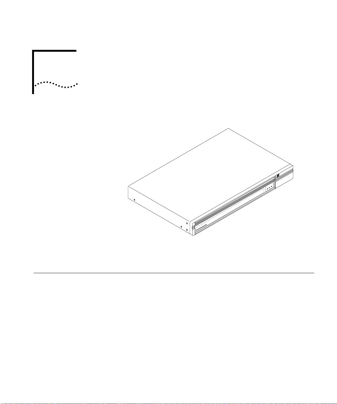
1
NTRODUCTION
I
SYSTEM STATUSSYSTEM STATUS
ActivityActivity
4000
AccessBuilder
PowerPower
StatusStatus
General
This chapter provides a brief introduction to the AccessBuilder 4000
system. Unpacking instructions are also provided.
The AccessBuilder 4000 series family are RISC-based multiprotocol,
multiport networking devices offering a simple and cost-effective
solution for remote users to access the corporate network for data
transmission or retrieval using the Public Switched Telephone Network
(PSTN), or the Integrated Services Digital Network (ISDN).
The system is designed for individual-to-LAN operation, which supports
situations where Macintosh, PC, and workstation users need to access
their corporate network from home or another remote location. The
AccessBuilder 4000 can also be used to connect two distant/remote
LANs over the PSTN, ISDN, or leased line facilities.
Page 10

1-2
HAPTER
C
NTRODUCTION
1: I
The AccessBuilder 4000 is designed for enterprise organizations having
remote LAN access requirements. It is well-suited for situations where
up to sixteen analog phone lines or up to eight ISDN lines (one line
supports two B channels providing up to 16 concurrent ISDN
connections) are required to support remote users who may include
business travellers or telecommuters.
The AccessBuilder 4000 is capable of routing IP and IPX protocols,
while protocols supported in the bridging mode include:
TCP/IP
■
■
IPX
■
AppleTalk Remote Access
NetBeui
■
■
DECNet
■
Banyan Vines
DECNet
■
■ XNS
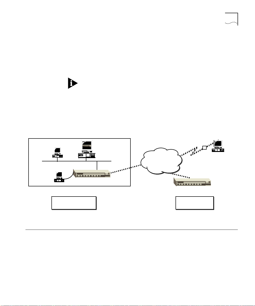
The AccessBuilder 4000 can be configured for individual-to-LAN,
LAN-to-LAN operation, or both depending on your needs. Figure 1-1
shows the two different configuration options.
Configuration Specific configurations are easily accomplished using 3Com’s easy to
use Transcend AccessBuilder Manager (TABM), a Windows-based
graphical user interface configuration utility. TABM features a detailed
graphic depiction of the hardware configuration of your selected
AccessBuilder, which serves as a navigational roadmap of AccessBuilder
functions. Built into TABM is a comprehensive on-line help system
providing in-depth context-sensitive help on demand. A convenient
“cue card” facility is also provided to display procedural information in
a separate window. TABM also includes a tool that automatically
discovers AccessBuilders on your network.
Configuration can also be performed using the AccessBuilder 4000’s
command line interface from either a locally connected terminal or over
the network via telnet for those more comfortable with a
DOS/UNIX-like command structure (requires optional support
documentation).
Page 11
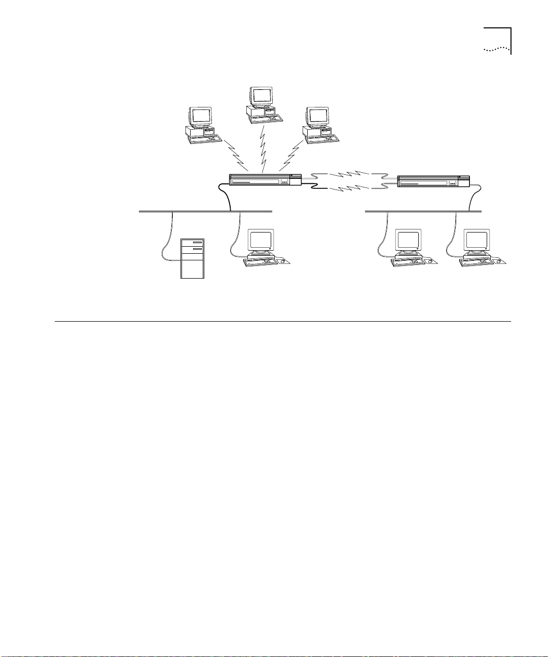
PC
System Description 1-3
Individual
to
LAN
SYSTEM STATUSSYSTEM STATUS
StatusActivity Power
AccessBuilderAccessBuilder
PC
40004000
LAN–to–LAN
LAN–to–LAN
Remote Access Server
net 2
AccessBuilderAccessBuilder
40004000
SYSTEM STATUSSYSTEM STATUS
StatusActivity Power
Work StationWork Station
net 1
PC
File Server
Individual
to
LAN
Remote Access Server
Work Station
Figure 1-1 AccessBuilder 4000 Configuration Options
System Description The AccessBuilder 4000 series servers consists of hardware and
software that provides a cost-effective solution to your remote access
networking needs. Both the Ethernet and Token Ring versions offer the
same high performance RISC-based engine. Optional plug-in line
interface modules may be installed to provide connections to a variety
of WAN types. These interface modules include 4-port, 8-port, and
8-port high speed serial cards for connection to analog modems, a
4-port ISDN Basic Rate Interface (BRI) interface (U or S/T), and a high
speed synchronous interface for leased lines.
Connection to the LAN supports three Ethernet media types, 10BaseT,
BNC (thin), and AUI. A three-position switch selects the desired
interface connection. The Token Ring version supports 4 or 16 Mbps
ring speeds.
A console port preconfigured for 9600 bps is provided as a
convenience when:
■ local configuration (using a dumb terminal or computer
communications emulation program) is desired, or
■ remote software downloading is desired.
Page 12
1-4 CHAPTER 1: INTRODUCTION
Hardware
Description
The following sections describe the system hardware components.
The AccessBuilder 4000 system consists of a chassis assembly which
contains one of two available main processor boards, power supply,
indicator lights, and two slots for I/O cards of your choice. The main
processor board is available with either an Ethernet, or a Token Ring
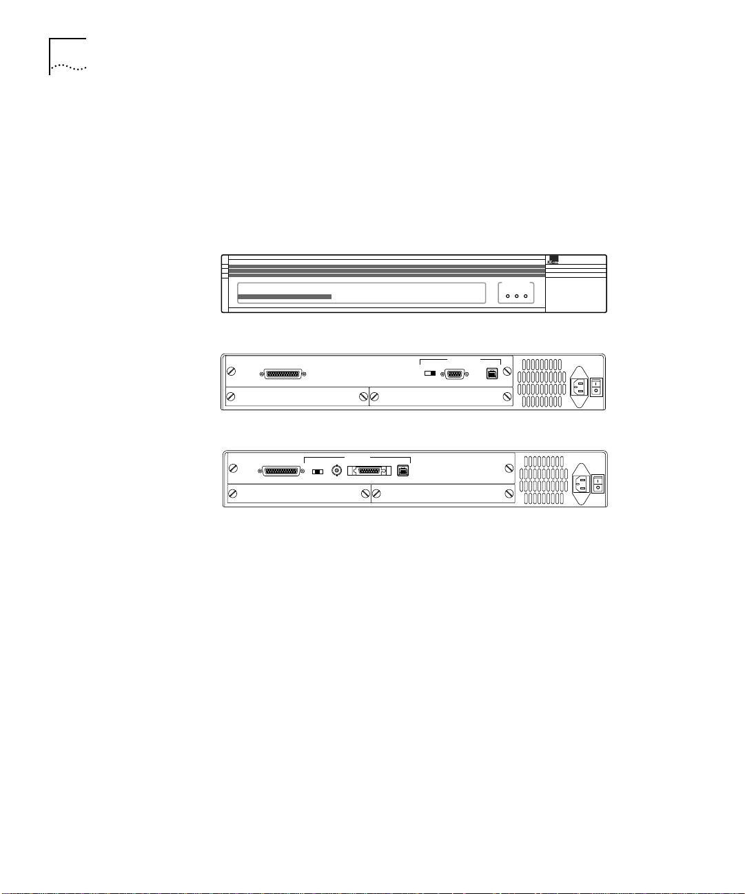
LAN interface. Figure 1-2 shows the front and back of the system.
AccessBuilder
4000
SYSTEM STATUSSYSTEM STATUS
Remote Access Server
Front Panel
TOKEN RING
STP
CONSOLE
SLOT 2 SLOT 1
4M/16M
Rear Panel Token Ring
CONSOLE
SLOT 2 SLOT 1
BNC/AUI/TPE
ETHERNET
BNC
TPE
AUI
Rear Panel Ethernet
StatusActivity Power
110-240 VAC
UTP
50-60 Hz 1A
110-240 VAC
50-60 Hz 1A
Figure 1-2 The AccessBuilder 4000 Front and Rear Panels
Front Panel The front panel of the AccessBuilder chassis has three LEDs, which
indicate Power, Status, and Activity, as shown in Figure 1-2.
Rear Panel Main Processor and I/O Card Slots. AccessBuilder has three slots in
the rear. The top slot contains the main processor board (Ethernet or
Token Ring) and the two smaller slots below are for the I/O cards. The
position of the slots and their numbering scheme are also shown in
Figure 1-2.
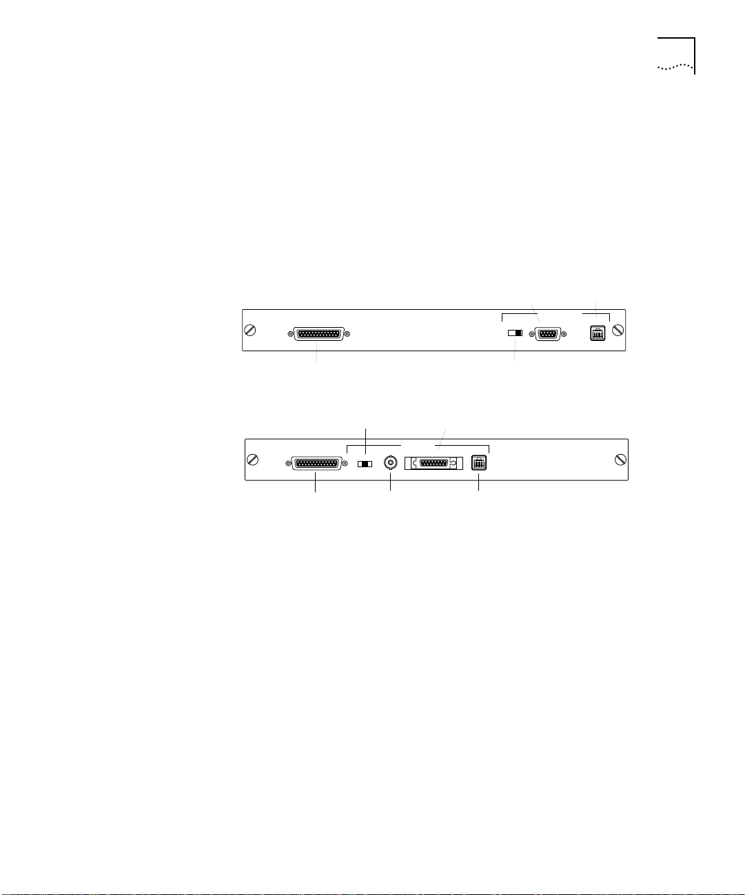
The main processor board has Flash ROM for program storage, DRAM
for software operation, NVRAM (non-volatile RAM) for configuration
storage, and built-in Ethernet or Token Ring capability. The Ethernet
version provides AUI, BNC, and 10BaseT connectors (switch selectable),
as shown in Figure 1-3 to connect to the on-board Ethernet port. The
Token Ring version provides connectors for shielded twisted pair (STP),
Page 13
System Description 1-5
and unshielded twisted pair (UTP) media connections. Ring speeds of
4Mbps or 16Mbps can also be selected.
A built-in RS-232 console port (DCE) is also provided on the main
processor boards (pinout information is provided in Appendix A). A
terminal or workstation running a terminal emulation program can be
connected to the console port for installing, configuring, and
monitoring your server.
TOKEN RING
CONSOLE
SLOT 2 SLOT 1
Console Connector
(DCE)
ETHERNET
CONSOLE
SLOT 2 SLOT 1
Console Connector
(DCE)
Media Type
Switch
BNC/AUI/TPE
BNC
Connector
BNC
AUI
Connector
ETHERNET
AUI
TPE
10BaseT
Connector
STP
Port
4M/16M
Ring Speed
Switch
TOKEN RING
STP
UTP
Port
UTP
Figure 1-3 Main Processor Boards
The I/O card slots shown in Figure 1-2 are shipped from the factory
with cover plates which must be removed before installing I/O cards.
For instructions on installing I/O cards, refer to Appendix C, “Installing
I/O Cards.”
The chassis assembly contains a bus that rests vertically against the
backplane of the card cage. DIN connectors secured on the backplane
mate with DIN connectors secured to the main processor and I/O cards.
Power Supply. The power supply module consists of the power
supply itself which adjusts (autoranges) the supply voltage to the
AccessBuilder chassis automatically. No operator intervention is
required for switching between 90 and 240-VAC operation.
Page 14

1-6 CHAPTER 1: INTRODUCTION
Power Switch and Receptacle. The AC power switch is marked
according to international 1/0 convention; when the 1 side is pressed,
the switch is on; when the 0 side is pressed, the switch is off. The
switch and power receptacle are accessible from the right rear of the
chassis.
The international CEE-22 AC power receptacle is approved for 6-amp
operation. The chassis ground is on the middle prong of the connector.
All systems are shipped with power cords; if your power cord does not
match your local requirements, contact your AccessBuilder supplier for
assistance.
Flash Memory. Flash memory on the processor board is used to
permanently store the AccessBuilder operating software. There are no
installation disks involved (unless upgrading to a newer version of the
operating software). Each system arrives from the factory with all of its
server software already loaded into flash memory.
Console Port. A built-in RS-232 console port (DCE) is also provided
on the chassis rear panel. Should you wish to use the command line
user interface for installing, configuring, and monitoring your server, a
terminal or workstation running a terminal emulation program can be
connected to the console port (using a straight through cable). The
console port is DB-25.
Error messages and remote user connection information are output to
the console port as these events occur. Attachment of this port to a
line printer or PC running a terminal emulator with a screen save utility
can be used to capture these messages for diagnostic use.
A modem may also be attached to this port (using a null modem cable)
to enable software updating from a remote server.
Page 15
2
GETTING STARTED
This section is designed to help you to quickly perform the installation
of an AccessBuilder 4000 network remote access server. Once you have
planned your installation and set up the hardware, you are then ready
to install and launch the Transcend AccessBuilder Manager (TABM)
configuration utility. From there, you’ll configure your AccessBuilder
using TABM’s on-line help information as required to perform specific
configuration items.
Before the Transcend
be used, the following condition must be true:
IP Networks: Your third-party TCP/IP stack must be installed and you
can ping a known host on the network.
IPX Networks: Your NetWare Windows client software must be
installed and you can attach to a NetWare server. A NetWare server
must also reside on the network to which the AccessBuilder is
attached.
AccessBuilder Manager configuration utility can
AccessBuilder
Configuration:
Windows or
Command Line UI
Nearly all AccessBuilder configuration can be performed using the
Transcend AccessBuilder Manager (TABM) configuration utility in a
Windows environment. There are, however, situations where it is
necessary to use the AccessBuilder’s command line interface to perform
specialized configurations. These situations include:
■ When a Windows platform with a third-party TCP/IP stack (IP
networks) or NetWare Client is not available on the network to
which the AccessBuilder is attached
■ When it is more convenient to use a local console on the
AccessBuilder’s asynchronous port
■ When using telnet (IP networks) to configure the AccessBuilder
■ When configuring bridging filters (refer to the Release Notes for any
other special circumstances)
Page 16

2-2 CHAPTER 2: GETTING STARTED
Should any of these special circumstances apply to your situation,
information about performing the software configuration using the
command-line interface is provided in the AccessBuilder Command Line
Interface Quick Reference, part number 09-0208-000, and the optional
AccessBuilder Configuration Guide, part number 09-0962-000, and
the AccessBuilder Administrator’s Guide, part number 09-0963-000.
You can obtain a copy of these guides through your normal 3Com
ordering channel.
Preparation Be sure to read the Release Notes included in this package. They
contain important late-breaking information about this software
release of which you should be aware.
Briefly, the basic categories of information you will need to obtain
before actually performing an installation are:
1 Modem/TA compatibility. Verify that the modems/terminal
adapters you intend to use with the AccessBuilder 4000’s WAN ports
are compatible with the unit. In the case of an ISDN application, be
sure to your phone company has furnished you will all necessary line
provisioning information.
2 User list. Determine all required information for each of the remote
users who will be calling into the AccessBuilder 4000.
3 Network basics. You will need to know your network protocol (IP or
IPX), the address that will be assigned to the AccessBuilder 4000 and
your Transcend management workstation, and the address of your
SNMP management station (if used).
4 AccessBuilder 4000 management method. Methods include:
■ using Transcend AccessBuilder Manager on a Windows PC
over the network (recommended method),
■ using Transcend AccessBuilder Manager on a Windows PC
running the AccessBuilder Remote Client software over a modem
into one of the AccessBuilder’s asynchronous ports,
■ using a third-party network management application,
such as HP OpenView, IBM’s NetView, etc., in conjunction with the
AccessBuilder MIB (supplied),
■ using the AccessBuilder’s command line user interface
through the local console port, remotely through a modem on the
console port, or by using telnet over the network.
Page 17
Preparation 2-3
Configuration worksheets are provided in Appendix D as a convenient
means of collecting and organizing this information.
Table 2-1 AccessBuilder Management Environments and Options
Manager Environment AccessBuilder 4000 Management Options
Workgroup Management ■ Transcend AccessBuilder Manager for Windows
Enterprise Management ■ Transcend Enterprise Manager for Windows
Console Management
(VT-100 character mode)
Third Party SNMP
Manager with MIB
Browser, such as:
■ SunNet Manager
■ HP OpenView
■ IBM NetView/6000
(bundled with product)
■ Console port access (RS-232/DCE)
■ Dial-in access
■ Telnet access (default port = 3000)
■ GET - SET supported
■ Traps defined
■ MIB II and private MIB extensions (AccessBuilder
MIB included with product)
Modems/ISDN TAs
1 Check to be sure the modems or terminal adapters you intend to use
are on the built-in modem list (or check the modem list in the Release
Notes). This list contains all modems or terminal adapters that have
been tested by 3Com and are supported for use with the AccessBuilder.
If your modems/terminal adapters are not on the list, you may need to
contact the manufacturer for assistance if script information is not provided
in the modem documentation.
For ISDN installations, refer to the AccessBuilder 4000 ISDN Basic Rate
Interface (BRI) Module Installation Guide for ISDN installation procedures.
All modems have unique AT command sets, even those claiming to be
“AT-compatible.” Use of an improper modem script may result in
transmission disruption, loss of carrier, failure of modems to answer,
slow response time and other serious problems that will hamper overall
performance. 3Com highly recommends using modems on the
AccessBuilder’s built-in modem list.
Page 18

2-4 CHAPTER 2: GETTING STARTED
For ARA and non-AppleTalk users to share the same ports, the use of
AppleTalk Remote Access version 2.0 or later is recommended. If,
however, you plan to support ARA 1.0, you will need to determine
which asynchronous serial ports to use, since these ports will be
dedicated to ARA 1.0 only.
2 You will need a list of telephone numbers for each modem or ISDN line
(or hunt group) connected to the AccessBuilder’s ports (these are the
numbers your remote users will use to dial into the AccessBuilder). If
you plan to use a modem on the AccessBuilder’s console port for
remote management, you will also need the telephone number
associated with this modem.
User List If you plan to use the AccessBuilder for individual-to-LAN service, it’s a
good idea to have a list of your remote access users including:
■ user name and password
■ callback number (if used), or modem line/phone number you wish
to assign to each user (note that callback only works when the
client is using the AccessBuilder Remote Client software or ARA).
■ type of access required (restricted, third-party security device used,
etc.)
For AppleTalk ARA users, be sure to install Apple’s ARA client software
on each user’s Macintosh computer.
For PC users, please refer to the AccessBuilder Remote Client Quick
Installation Guide for client software installation procedures.
If your remote users will be using the AccessBuilder Remote Access
Client software on their PCs to access the network, a convenient
fill-in-the-blank form (an exact screen shot of what they will see) is
provided in Appendix D of this Guide. This form may be photocopied
and customized for each user to include all the information they will
need to configure their AccessBuilder Remote Client software. The form
may then be sent or faxed to the user and filed for future reference.
Network Basics You will need to know the network address (IP networks) which will be
assigned to each AccessBuilder being configured, the protocols used on
the network, and whether any automated network functions are used,
such as RIP or ARP in the case of IP.
Page 19
Unpacking the System 2-5
If you plan to use SNMP functions, such as trap reporting or remote
device management, you will also need to know the community names
and IP addresses of the management station(s).
You may also wish to define the greeting message the remote users
will see when they log onto the AccessBuilder.
If the AccessBuilder greeting message will be more than one line, use
the vertical bar character (|) as a carriage return. Refer to the Transcend
AccessBuilder Manager System Dialog box on-line help for details.
AccessBuilder
Management
Console, accessed
via telnet
Console, accessed
via console port
Central Site
AccessBuilder(s)
Unpacking the System
You will want to consider how the AccessBuilder 4000 will be
managed. Figure 2-1 illustrates the methods of managing the
AccessBuilder family.
Transcend AccessBuilder
Manager for Windows
(SNMP w/GUI)
Analog or
ISDN Telco
Network
AccessBuilder 4000 or 2000
AccessBuilder 4000 or 2000
Remote Site
AccessBuilder
Figure 2-1 Managing the AccessBuilder
To unpack the system:
M
Console, accessed
remotely via
dial-up connection
1 Remove the unit from the original shipping carton.
2 Inspect the chassis for shipping damage.
If you find any damage, contact the shipping company to file a report.
If the chassis must be returned to the factory, repack and ship it in the
original shipping cartons.
Page 20

2-6 CHAPTER 2: GETTING STARTED
If the original carton was damaged in shipment, repack the system in a
carton that provides equivalent protection before returning it to 3Com.
3 Verify that you have received all items included with the unit.
Hardware AccessBuilder 4000 Chassis
Software 1 CD-ROM
Documentation Information Roadmap
Rack Adapter Kit
Power Cable
BNC Connector
AccessBuilder 4000 Installation Guide
Remote Client Installation Guide
AccessBuilder Server Release Notes
Remote Client Release Notes
If you have not received all items on the packing list, first check the
Release Notes for any late changes, then contact your AccessBuilder
supplier for assistance.
4 Verify that the AccessBuilder 4000 system's power specifications listed
in Appendix A corresponds to your facility's available power source.
If the available power source does not correspond to the acceptable
range, contact your AccessBuilder supplier for assistance.
5 Write down the serial number of the chassis and the MAC address.
The serial number and MAC address are listed on labels on the bottom
of the unit. The label contains the UL listing, FCC numbers, and the
serial number with a bar code.
WARNING: Before powering on the system, make sure that the cover is
properly secured in place. Powering on the system without the cover in
place can result in overheating the system and the potential for electric
shock.
Page 21
Hardware Installation 2-7
Hardware Installation
Stand Alone Pick a suitable location for the AccessBuilder 4000. Either a desktop or
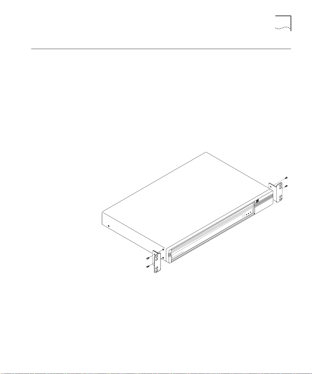
Rack Mounting If rack mounting is desired, attach the rack adapter ears (included) as
The following is a step-by-step procedure for performing the
AccessBuilder 4000 hardware installation.
similar level surface may be used. You may also want to locate the
modems near the unit. Be sure there are no obstructions on the sides
of the AccessBuilder to permit adequate airflow for cooling.
show in Figure 2-2. The AccessBuilder 4000 requires 1.5 RU (rack unit)
of height in the rack. Be sure there are no obstructions on the sides to
permit adequate airflow for cooling.
4000
AccessBuilder
PowerPower
SYSTEM STATUSSYSTEM STATUS
StatusStatus
ActivityActivity
Figure 2-2 Rack Ears Installation
Page 22
2-8 CHAPTER 2: GETTING STARTED
LAN Connection
(Mandatory)
This connection is required in either Ethernet or Token Ring
environments.
Ethernet
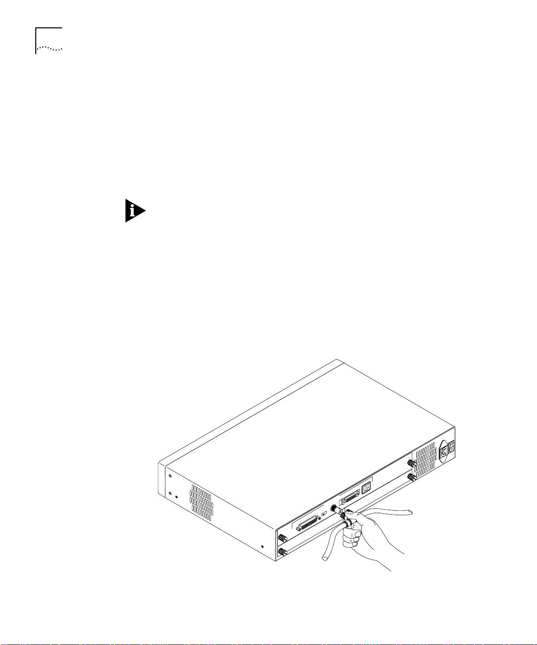
1 Connect your Ethernet LAN to the appropriate interface connector for
your media type (10BaseT, BNC, or AUI). These connectors are located
on the rear panel. If a 10Base5 (thick Ethernet) connection is required,
use a third-party AUI to coax transceiver. Move the media selector
switch to the appropriate position.
When using an external 10Base5 (thick Ethernet) transceiver, the
AccessBuilder’s LAN controller test will fail if the BNC interface is NOT
terminated. If this happens, be sure that a 50-ohm BNC termination
resistor is installed on each end of your cable run and reboot the
system.
2 Install and connect your I/O card (or cards) to your modems, CSU/DSU,
ISDN line, etc. Refer to Appendix C for details.
3 (Console connection -- optional step) Connect a terminal or a PC
running terminal emulation (DTE) with a straight-through cable to the
AccessBuilder’s console port (DCE). Default settings are 9600 Baudrate,
8 bits, 1 stop bit and no parity.
UTP
AUI
ETHERNET
BNC
BNC/AUI/TPE
CONSOLE
Thin Ethernet
SLOT 2
Connection
Figure 2-3 AccessBuilder Ethernet Thin LAN Connection
110-240 VAC
50-60 Hz 1A
SLOT 1
Page 23
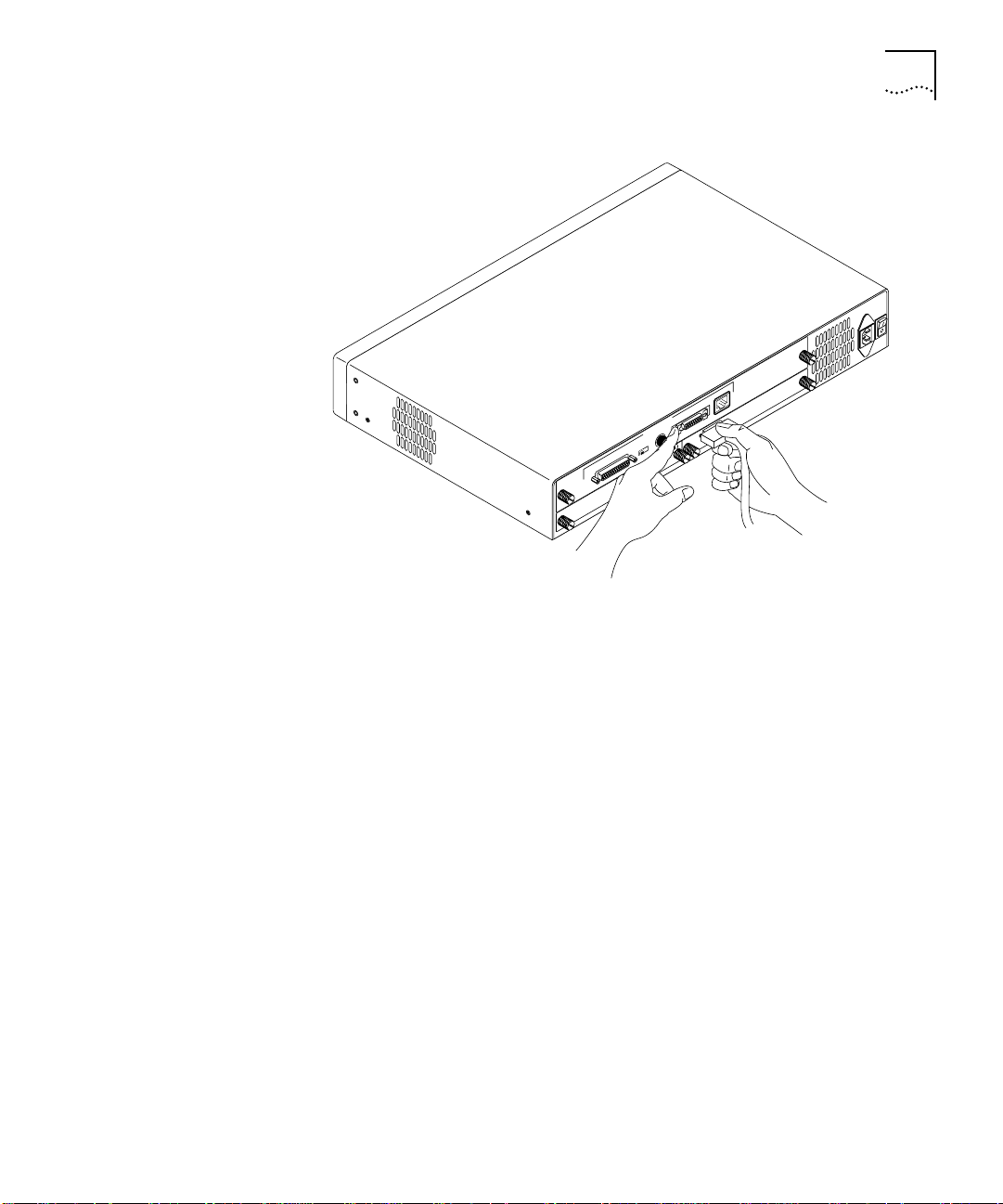
Hardware Installation 2-9
110-240 VAC
50-60 Hz 1A
UTP
AUI
ETHERNET
BNC
BNC/AUI/TPE
CONSOLE
SLOT 2
SLOT 1
AUI Connection
Figure 2-4 AccessBuilder Ethernet AUI LAN Connection
Token Ring
1 Set the Token Ring 4M/16M speed switch to the appropriate ring speed
and attach the AccessBuilder to your ring.
2 Install and connect your serial card (or cards) to your modems,
CSU/DSU, ISDN line, etc. Refer to Appendix C for details.
Power Up If you plan to use TABM to manage the AccessBuilder over an IP
network, be sure the TABM software has been installed and launched
on your management workstation before you power up the
AccessBuilder 4000. Otherwise the BootP requests (for assigning an IP
address) issued by the newly installed AccessBuilder will not be “heard”
by TABM.
Proceed to Chapter 3 to install the TABM software on your Windows
workstation. Once TABM has been installed and launched, newly
installed AccessBuilders on the network will be identified by the
TABMTOOL utility (IP only).
Page 24
2-10 CHAPTER 2: GETTING STARTED
When more than one AccessBuilder is installed on the network (IP or
IPX), record the MAC address of each unit (located on the rear panel)
so you will know which one you are configuring from TABM.
The Power indicator on the front panel will glow when the
AccessBuilder has been powered on.
Console/Modem
Configuration
(Optional)
If you have decided to configure the AccessBuilder locally using a
console, or wish to perform remote downloading of configuration or
system software, or wish to monitor the AccessBuilder, perform the
following:
For Terminal Connection
Connect a terminal or a PC running terminal emulation (DTE) with a
(user supplied) straight through cable to the AccessBuilder’s console
port (DCE). Default settings are 9600 Baudrate, 8 bits, 1 stop bit and
no parity.
After powering up the AccessBuilder, power-up tests and the 3Com
copyright notice should appear on the screen.
If you are not attached to a NetWare LAN right now (i.e., you are on
an IP network), you may see the following message "The IPX Network
for LocalPath ethernet couldn't be learned", this is due to
AccessBuilder's autoconfiguration function in a NetWare environment:
you can ignore this message.
Press the <CR> key once or twice to produce the login prompt. If the
login prompt fails to display, check the following:
■ Proper power service by confirming that the power light on the
front of the AccessBuilder unit is on.
■ Proper cabling configurations.
■ Proper terminal parameters.
If you still cannot obtain the login prompt, call your AccessBuilder
supplier or 3Com for technical assistance.
Page 25

Console/Modem Configuration (Optional) 2-11
For Modem Connection
(Remote AccessBuilder Management Only). Connect the modem
(a DCE device) to a null modem cable conforming to the VT-100
specification to the AccessBuilder’s console port (also DCE) on the rear
panel. The modem should be set to power up with default settings of:
9600 Baudrate, 8 bits, 1 stop bit and no parity.
It may be necessary to first connect the modem to a terminal in order
to reconfigure the modems’ default settings to autoanswer, etc. (refer
to your modem documentation for this procedure). Once this is
accomplished, the modem connection can be moved to the
AccessBuilder 4000’s console port.
Telnet Users (IP Only) If you wish to use Telnet to perform configuration, the \must
first have an IP address. This can be accomplished two ways:
1 Using TABMTOOL to detect the AccessBuilder’s BootP request, then
assigning the IP address through TABM’s AccessBuilder Configuration
Parameters dialog box. Note the TABM management station and the
AccessBuilder must on the same subnet.
2 Using the AccessBuilder’s command line user interface via a modem or
local console. Refer to the section “Setting the AccessBuilder’s IP
Address” in the Procedures section of TABM’s on-line help or Chapter 2
of the AccessBuilder Configuration Guide.
The Telnet default port in TABM and the AccessBuilder is 3000. If you
need to change the default, use the System dialog box in TABM to
change the selected AccessBuilder. To change the default on your
workstation, refer to your Telnet third-party documentation for
procedures.
SNMP Management If you wish to manage or obtain operational statistics for the
AccessBuilder via an SNMP based network management station, such
as HP OpenView or SunNet Manager, an AccessBuilder Enterprise
MIB is included on the backup diskette for this purpose. Refer to the
documentation provided with your network management MIB
compiler/parser software for instructions on how to integrate the
AccessBuilder MIB.
Note that in the case of an IP network, you must have previously
assigned an IP address to the AccessBuilder(s) you wish to manage.
Page 26

2-12 CHAPTER 2: GETTING STARTED
Page 27

CONFIGURATION USING
T
3
General The Transcend AccessBuilder Manager (TABM) application is a Microsoft
RANSCEND ACCESSBUILDER
M
ANAGER (TABM)
Windows-based tool for configuring and managing AccessBuilder
remote access servers. Features include:
■ Automatic discovery of all AccessBuilder servers that respond on
the network
■ At-a-glance list of all servers known to the application
■ External view of an AccessBuilder server showing status of any
installed ports
■ Menu-driven quick installation of new AccessBuilder servers
■ Password protection
■ Detailed on-line help
This section contains the following:
■ System Requirements
■ Installing the TABM Application
■ About the TABM Application and its on-line help
■ Starting the TABM Application
■ Starting Up a New Server
■ Configuring a Server Using Guided Configuration or Basic
Configuration
Basically, the purpose of this chapter is to help you get TABM installed
and launched, then pass you to TABM’s on-line help for configuration
procedures. If you plan to perform the AccessBuilder configuration
through the AccessBuilder’s command line interface, refer to the
optional AccessBuilder Server Configuration Guide for detailed
information about the various parameters and procedures involved in
setup.
Page 28

3-2 CHAPTER 3: CONFIGURATION USING TRANSCEND ACCESSBUILDER MANAGER (TABM)
System Requirements
Hardware
For best performance, the following system resources are
recommended:
■ A 486 or better platform
■ A hard disk with at least 3.5Mb of available space
■ At least 16Mb of RAM
■ A VGA video card and VGA compatible color monitor or better
(SVGA recommended)
■ A network adapter card compatible with your TCP/IP or IPX software
If you plan to use this application with a laptop computer that does not
include a color VGA display, be sure the display supports at least 16
shades of greyscale. Bear in mind, however, that you will lose certain
color-highlighted information, such as the async port status, etc.
Software
TABM 4.0 for IP is a 32-bit application which is compatible with
Microsoft Windows 95 and Windows NT. TABM 4.0 for IPX is a 16-bit
applicaiton which is compatible with Windows 3.1 and Windows 95.
3Com also offers a UNIX version of TABM.
Before installing TABM, be sure your network client software is
functional on your workstation. For IP networks, you should be able to
ping a known host on the network. For IPX networks, you should be
able to attach to a host on the network. Successful connection from
the workstation on which you plan to install TABM to the network is
required.
IP Networks. This utility requires that you have Windows 95 or
Windows NT installed on your PC. Be sure your TCP/IP stack is installed
before installing the TABM application. Within your TCP/IP stack, you
will also need to set the TCP connections to a minimum of 12.
IPX Networks. This utility requires that you have Windows version 3.1
or later installed on your PC, and Novell NetWare Windows Client
version 3.12 or later. You must also have a NetWare server on your
network.
Page 29

TABM Software Installation 3-3
TABM Software Installation
Version 4.0 of the Transcend AccessBuilder Manager application is
provided on CD-ROM. An extraction utility is provided to automatically
install the TABM software from the CD-ROM to your local hard drive, a
network server hard drive, or onto two diskettes.
Once installed, TABM is then used to configure your AccessBuilder
remote access servers. For convenience, basic configuration
information can be collected using the Configuration Worksheets
provided in Appendix D.
The following functional key conventions are used within TABM:
Key Label Function
Apply Apply changes made to the AccessBuilder, but leaves the dialog
box open.
Change Store the changes made locally without sending them to the
AccessBuilder.
The following procedure assumes installation from diskettes. If you are
installing from CD-ROM, refer to the instructions in the CD-ROM insert.
1 Start Microsoft Windows, and open the Program Manager window.
2 Insert the diskette labelled “Transcend AccessBuilder Manager for
Windows, Diskette 1” into a diskette drive on the Windows
workstation.
3 From the File menu, choose Run [Alt] + [F] + [R].
4 In the Run dialog box edit box type A:\SETUP and choose OK to invoke
the installation utility.
If you used a diskette drive other than drive A, use that drive’s
designator instead of A: before the SETUP command (for example,
B:\SETUP).
5 The AccessBuilder Manager Setup dialog box appears with a message
indicating initialization is occurring. After the initialization process has
finished, the Welcome dialog box appears. Choose the Continue
button to proceed with installation.
Page 30

3-4 CHAPTER 3: CONFIGURATION USING TRANSCEND ACCESSBUILDER MANAGER (TABM)
Figure 3-1 Welcome Dialog Box
6 The Registration dialog box appears. Enter your name and company
name and then choose the Continue button to proceed with
installation.
Figure 3-2 Registration Dialog Box
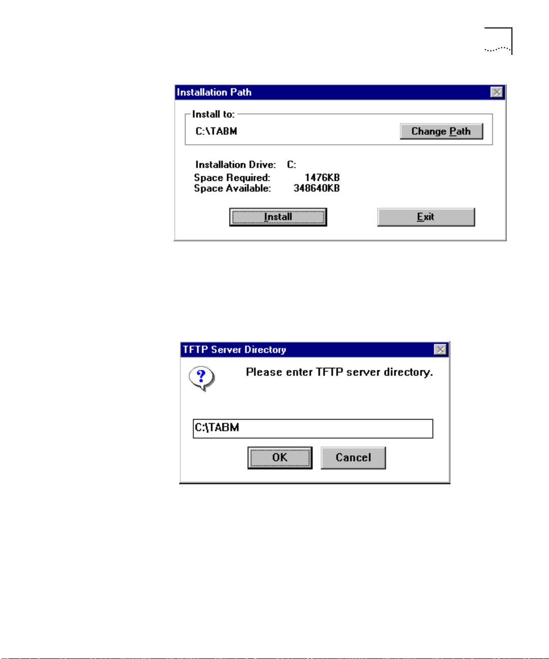
7 The Installation Path dialog box appears (Figure 3-3). If you want to
change the directory or drive, choose the Change Path button and
enter the desired destination (refer to your Configuration Worksheets).
When you are satisfied with the installation path, choose the Install
button to proceed with installation.
Page 31
TABM Software Installation 3-5
Figure 3-3 Installation Path Dialog Box
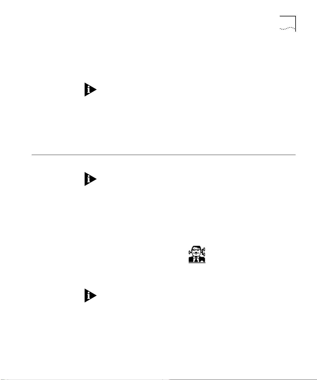
8 (IP Only) The TFTP Server Directory box appears (Figure 3-4) and
requests the path of the TFTP server, which is used to upload and
download AccessBuilder configuration and system files from and to
the AccessBuilder server from a computer’s disk file.
Figure 3-4 TFTP Server Directory Dialog Box
If the TFTP server is on the same computer on which you are installing
the TABM software, enter the path to the TFTP server now, then click
the OK button.
If the TFTP server is on a different system, or you do not plan on using
the upload/download feature, click the Cancel button now.
Page 32

3-6 CHAPTER 3: CONFIGURATION USING TRANSCEND ACCESSBUILDER MANAGER (TABM)
If your TFTP server is installed on a different computer, be sure to copy
the following files from the “Transcend AccessBuilder Manager for
Windows” installation diskette to the hard disk directory that contains
the TFTP server application files: ABUPCFG.HD0, ABUPCFG.HD1,
ABUPCFG.HD2, ABDNCFG.HD0, ABDNCFG.HD1, and ABDNCFG.HD2.
9 (IP Only) The AskPath dialog box appears (Figure 3-5) and requests the
path of the Ping and Telnet utilities included with your TCP/IP stack.
Note that both program files must be in the same directory. Enter the
full path of the directory containing the Ping and Telnet utilities. If the
program names of the utilities differ from those shown in the Ping and
Telnet utility file edit boxes, make the necessary changes now. Choose
the OK button to proceed with installation.
Figure 3-5 AskPath Dialog Box
Table 3-1 list this information for a few popular TCP/IP packages. For
additional information, refer to the documentation provided with your
TCP/IP package.
Page 33

TABM Software Installation 3-7
Table 3-1 Common TCP/IP Package Path Information
Application Manufacturer Path Ping Telnet
PCTCP FTP Software Inc. C:\PCTCP wping.exe wtnvt.exe
LAN Workplace Novell Inc. C:\NET\BIN ping.exe tnvt220.exe
PATHWAY Wollongong C:\PATHWAY winping.exe pwvt340.exe
Super TCP Frontier Technologies C:\SUPERTCP wping.exe vtterm.exe
Chameleon NetManage C:\NETMANAG ping.exe telnet.exe
10 At this point, you are prompted to replace the first diskette with the
second distribution diskette.
11 After the application files are copied to your hard disk, the Installation
Complete dialog box is displayed (Figure 3-6):
Figure 3-6 Installation Complete Dialog Box
12 To view the help file choose the Yes button. To bypass the help file,
choose the No button.
The TABM setup utility creates a Transcend AccessBuilder Manager
program group in the Program Manager window (TABMTOOL icon not
present if IPX).
Page 34

3-8 CHAPTER 3: CONFIGURATION USING TRANSCEND ACCESSBUILDER MANAGER (TABM)
Figure 3-7 AccessBuilder Manager Program Group (TABMTOOL not in IPX)
The AccessBuilder Manager program group contains three icons:
■ TABM Starts the AccessBuilder Manager application.
■ TABMTOOL (IP Only) Starts the AccessBuilder Manager Tool
(TABMTOOL) application and identifies newly installed AccessBuilders
so they can be given a network identity. This application is started
automatically when you run the TABM application, so you do not
need to start it manually.
TABMTOOL runs in the background “listening” for BootP requests
issued by a newly started AccessBuilder. Upon “hearing” a BootP
request from an AccessBuilder, (on the same network segment or
across a router) TABMTOOL displays a dialog box enabling the new
AccessBuilder to be assigned a network IP address and secured with
a unique Superuser password. The icon is included in the program
group so that you will recognize it when it appears on the screen
during an TABM session.
■ TABM Help Launches Windows help for the TABM application. You
can also launch Windows help from the TABM application from the
Help menu or by pressing the F1 key.
Page 35

About the TABM Application 3-9
About the TABM Application
Autodiscovery In addition to TABMTOOL listening for new AccessBuilder BootP
The TABM application is an easy-to-use, graphical environment for
configuring and monitoring AccessBuilder servers that are reachable
from your network.
requests, an autodiscovery facility is included. This facility issues a
proprietary UDP request to discover (previously configured)
AccessBuilders on the same network segment as the TABM
workstation. This request occurs automatically when TABM is
launched, or when the Autodiscover icon is clicked while TABM is
running.
A previously configured AccessBuilder residing on the opposite side of
a router on the same network segment as the TABM management
station cannot be discovered by TABM because the router cannot
bridge TABM’s special UDP requests. In this case the IP address of the
target AccessBuilder must be manually entered into TABM.
IP Networks
New servers that are connected to the network send configuration
requests (BootP requests) to the TABMTOOL application.
Upon receiving such a request, the application automatically displays a
dialog box so you can enter the required information. After you enter
the required information, the application (TABM) adds the new server
to the All Servers List, which is described in the next section.
Main Window (All
Servers List View)
IPX Networks
In IPX networks, the AccessBuilder Manager can auto discover the
AccessBuilders on the LAN without knowing the IPX address of the
management workstation on which it is running. All servers, including
those on different subnets that respond are added to the All Servers
List, which is described in the next section.
The main window appears when you first start the application. The
main window lists all servers known to the application by IP/IPX address
and user-defined name.
Page 36

3-10 CHAPTER 3: CONFIGURATION USING TRANSCEND ACCESSBUILDER MANAGER (TABM)
Menu Bar
Toolbar
Info read from
server highlighted
in Server List
Server List shows
all servers that
respond to auto
discovery
Status Bar
Status Bar
describes
current
function in
process
Displays the Single
Server External view
of the highlighted
AccessBuilder
Shows specific
information about
highlighted
server
Choose to add
a server
Choose to delete
highlighted
server
Use to change
AccessBuilder info
Accesses the online
help
AccessBuilder Server
External View
Figure 3-8 AccessBuilder Manager Main Window (IP version shown)
Highlighting any server in the All Server List displays information about
that server in the top half of the main window. The IP address and
name data fields in the statistics dialog box are editable, allowing you
to change the server’s name and add a new IP address.
To display the external view of any listed server, double-click that
server’s address/name in the server list of the main window.
The external view displays a graphical image of a single AccessBuilder
remote access server.
Page 37

About the TABM Application 3-11
Menu Bar
Tool Bar
Double-click this
area to view the
LAN statistics
dialog box
Name of server
Double-click this area to view the
Asynchronous Port dialog box for the
desired port
IP address of server
Double-click the logo for info on
the current software version
Figure 3-9 External View (Ethernet LAN Adapter shown)
Tool Bar Icons
The icons in the tool bar shown above are convenient shortcuts to
selecting commands from the Menu bar. They are defined in
Figure 3-10:
Front Panel of
the
AccessBuilder
2000
Rear Panel of
the
AccessBuilder
2000
Copy Server
Configuration
Verify
Config.
Download/
Upload
File
System
Protocols
Modem
Scripts
Async
Ports
Remote
Users
SNMP
Figure 3-10 Tool Bar Icon Definitions
Copy Server Configuration. Copies the current server configuration
to a specified AccessBuilder.
Verify Configuration. Displays current status of critical AccessBuilder
configuration information.
Page 38

3-12 CHAPTER 3: CONFIGURATION USING TRANSCEND ACCESSBUILDER MANAGER (TABM)
Download/Upload File . (IP only) Allows (1) AccessBuilder
configuration parameters to be uploaded to a specified TFTP server, (2)
configuration parameters to be downloaded from a specified TFTP
server to a specified AccessBuilder, (3) AccessBuilder server image to
be downloaded form a TFTP server to a specified AccessBuilder.
System Configuration Parameters. Opens a dialog box to
configure system-related parameters, such as server name, date, time,
greeting, etc.
Protocols. Allows specified protocol-related parameters to be enabled
or disabled.
Modem Scripts. Allows modem scripts to be added, created, edited
or deleted.
Async Ports. Allows the specified asynchronous port-related
parameters to be changed.
Remote Users. Allows remote user-related parameters such as phone
number, password, etc., to be added, deleted or changed.
SNMP. Allows defining or redefining of the set of SNMP
managers-related parameters or copying them to another
AccessBuilder server.
Conventions Port Color Conventions
The asynchronous ports are color-coded to show status, as shown in
the table below:
Table 3-2 Port Color Conventions
Color Meaning
White Not in use
Green In session (dial in)
Cyan (Greenish blue) In session (dial out)
Blue Disabled
Yellow Router (LAN-to-LAN)
Page 39
Starting the TABM Application 3-13
Double-click any asynchronous port in the graphical image to
configure asynchronous port parameters for that port. Use the
Configuration menu to access other configuration dialog boxes for the
displayed server.
The single server port status update process is automatically repeated
at an interval of n seconds, where n can be set to any value from 0 to
120 (the default time is 16 seconds).
@ Symbol
Throughout TABM’s dialog boxes, the @ symbol is used to indicate that
the respective parameter or group requires the AccessBuilder be reboot
in order for the new values to take effect.
Starting the TABM Application
The first time you start the TABM application, follow these steps:
If the host table of your TCP/IP stack contains the IP address of the
system running the TABM software, TABM program will use that IP
address. If the IP address is not available, the TABM program will ask
you to supply the IP address of the management system the first time
you run the TABM application (see step 2, below) and will save the IP
address for use thereafter.
1 From the Transcend AccessBuilder Manager program group,
double-click on the TABM icon:
2 The Transcend AccessBuilder Manager Login box then appears asking
for a password. Enter the factory default password: admin.
IP Only) If the IP address of the system running the TABM tool is not
available in the TCP/IP host table, a dialog box appears in which you
are requested to enter the management system’s IP address. Type in
the IP address in dot-delimited form (that is, separating each group of
numbers with period characters, i.e., 129.147.72.20). Then choose the
OK button.
Page 40

3-14 CHAPTER 3: CONFIGURATION USING TRANSCEND ACCESSBUILDER MANAGER (TABM)
3 At this point, you will want to change TABM’s login password from the
default to your own. From the Administration menu, choose Change
Password [Alt]+[A]+[C]. The Change Password dialog box appears.
4 In the Old Password edit box, type the default password: admin
5 In the New Password and Confirm Password edit boxes, type the new
password you want to assign to the TABM application.
6 Choose the OK button.
Starting Up a New AccessBuilder Server
IP Networks
When you run the TABM application (in a window or minimized as an
icon), it launches TABMTOOL to “listen” in the background for
configuration requests from new AccessBuilder servers (that is, servers
that have not yet been configured). When you connect such a server to
the network and power it up, the server sends configuration requests
(BootP requests) to the network which are intercepted by the
TABMTOOL.
Make sure the AccessBuilder is powered on after TABM is running. If
TABM is launched after the AccessBuilder has been power on, the
AccessBuilder’s BootP request will be missed.
Upon receiving a request for configuration parameters, the TABMTOOL
utility displays the AccessBuilder Configuration Parameters dialog box.
Use this dialog box to provide the following basic configuration
parameters:
■ IP address of the AccessBuilder
■ IP address of the system running the TABM application
■ Subnet mask for the AccessBuilder
■ Default gateway for the AccessBuilder (optional)
■ Super user password
IPX Networks
The AccessBuilder Manager can auto discover the AccessBuilders on the
LAN without knowing the IPX address of the management workstation
on which it is running. All servers, including those on different subnets
that respond are added to the All Servers List View window.
Page 41
Basic Configuration 3-15
Basically, an AccessBuilder only needs to be discovered in an IPX
network in order to proceed with it’s configuration. Once this occurs,
you are ready to perform either the Basic, or Guided Configuration.
What’s Next? Once the AccessBuilder has been discovered and you have entered the
initial configuration parameters itemized above and click the OK
button, this information is downloaded into the new AccessBuilder
which then appears in the All Servers List View. You now are ready to
proceed with a more specific AccessBuilder configuration.
1 From the All Servers List View, double click on the AccessBuilder you
wish to configure.
2 The SuperUser Password Dialog Box then appears asking for the
superuser password for your selected AccessBuilder. If this is a new
AccessBuilder that has never before been configured, simply press the
Return key (no SuperUser password).
3 You now have two choices: Basic Configuration, or Guided
Configuration.
At this point, refer to TABM’s on-line help and cue cards for further
instructions in performing the configuration procedure.
We recommend that you complete the Configuration Worksheets
provided in Appendix D prior to performing either Basic or Guided
Configuration for fastest and most accurate results.
Basic Configuration The TABM Basic Configuration selection is the quickest means of
getting an AccessBuilder up and running with a minimum configuration
for individual to LAN access for both IP or IPX networks.
Assuming you have entered the initial configuration parameters, the
Basic Configuration procedure can be completed:
1 From the Configuration menu, choose Basic Configuration.
2 Enter the System Greeting and the Time and Date information into
their respective edit boxes (use the on-line help as required).
3 Click on the Remote Users button. Enter the requested information for
each remote user (use the on-line help as required).
4 Click on the Async Ports button. Enter the requested information for
each port (use the on-line help as required).
Page 42

3-16 CHAPTER 3: CONFIGURATION USING TRANSCEND ACCESSBUILDER MANAGER (TABM)
Configuring an
AccessBuilder
Using Guided
Configuration
Guided Configuration enables a more comprehensive configuration of
the AccessBuilder than does the Basic Configuration.
When an AccessBuilder server is displayed in the external view window,
choose Guided Configuration from the System menu. Each of the
following dialog boxes are then displayed, in sequence:
■ System
■ Protocols
■ Asynchronous Ports
■ Remote Users
To perform a Guided Configuration, follow these steps (refer to the
on-line help as necessary):
1 Double-click the new server’s name/address in the list of servers
displayed in the All Servers List View. The single-server external view
appears for the server you selected.
2 From the Configuration menu, choose Guided Configuration. The
Guided Configuration procedure displays each required dialog box in
sequence.
3 Complete each dialog box (choose the Help button in each dialog box
for detailed instructions).
When you have finished filling out the last dialog box, the
AccessBuilder server is ready to use for individual-to-LAN operation. Be
sure your remote clients are configured to connect to the AccessBuilder.
Also note that the AccessBuilder must be reboot in order for the new
values to take effect.
Remote Client
Configuration
Once you have finished configuration of the AccessBuilder server, you
will want to ensure your remote clients have successfully installed their
remote access client software. Refer to the AccessBuilder server
Release Notes for current information regarding the various client type
supported.
AppleTalk Clients The AccessBuilder supports AppleTalk clients using the Apple Remote
Access (ARA) software. Refer to the Apple documentation provided
with the ARA software for installation details.
Page 43

Remote Client Configuration 3-17
PPP/SLIP Clients The AccessBuilder supports UNIX or PC-based PPP or SLIP clients. Refer
to the documentation provided with these packages and the
AccessBuilder Server Release Notes for specific types and versions
supported.
PC Clients The AccessBuilder Remote Client software is provided for use by
PC-based clients requiring remote LAN access. Refer to the
AccessBuilder Remote Client Quick Installation Guide and the on-line
help for instructions.
As a convenience, a remote client configuration worksheet is provided
in Appendix D. This worksheets can be customized and faxed to your
clients to aid in configuring the AccessBuilder Remote Client software.
Page 44

3-18 CHAPTER 3: CONFIGURATION USING TRANSCEND ACCESSBUILDER MANAGER (TABM)
Page 45

4
TROUBLESHOOTING
This chapter provides troubleshooting information which can be used
if the AccessBuilder or one of its components fails to operate correctly.
If after reviewing the information in this chapter, you cannot correct
the problem, contact your AccessBuilder supplier for further assistance.
System Does Not Power On
TABM Not Communicating with an AccessBuilder
If the system fails to operate after you power it on, try the following
procedures, one at a time, until the problem is solved.
1 Power off the system. Unplug the power cable from the wall outlet and
plug it in again; then power on the system.
2 Test for power at the wall outlet by plugging in another device.
Select another outlet on a different circuit if necessary.
If the unit does not appear on the list of AccessBuilders found
following the autodiscovery process, check the front panel LEDs for
activity. The Ethernet or Token Ring cable connections should then be
checked for proper electrical connections.
When operating dual protocols (IP and IPX) over the network segment
to which the TABM workstation is attached, TABM can manage
AccessBuilders only for the protocol selected. Once the Transcend
TABM application has been installed for either an IP or IPX network
type, it cannot be used to manage the other, i.e., when installed for IP,
TABM cannot manage IPX AccessBuilders.
Page 46

4-2 CHAPTER 4: TROUBLESHOOTING
IP Networks
1 Check to be sure you have your third-party TCP/IP stack installed
correctly. You should be able to ping a known host such as a router or
existing workstation.
2 Be sure the AccessBuilder and the TABM workstation are on the same
subnet. If the AccessBuilder and your TABM workstation are not on the
same subnet, you will need to assign a common SNMP community
name to the AccessBuilder and set up your workstation as the SNMP
community management station (see the TABM on-line help for
further information).
3 Verify that the AccessBuilder has been assigned an IP address. If the
BootP request issued by the new AccessBuilder when it was initially
powered on was not “heard” by TABM, you may need to power-cycle
the new AccessBuilder. Be sure TABM is running before the new
AccessBuilders are brought on-line.
If an AccessBuilder has been discovered (appears on the All Servers list),
but will not communicate when selected, one of the following may
have occurred:
IPX Networks
1 The AccessBuilder may have been powered off. Power it on and allow
one to two minutes for the BootP process to complete.
2 The Ethernet connection may have become disconnected or defective.
3 Someone else may have reset the AccessBuilder or altered its
configuration or SNMP community name via a telnet connection.
1 Check to be sure you have your Novell Windows NetWare client
software installed correctly. You should be able to attach to server on
the network.
2 Check your cabling and connections. Be sure your Ethernet connections
are correct and secure.
3 Make sure there is a NetWare server on the network to which the
AccessBuilder is attached. The AccessBuilder will automatically learn its
address from the NetWare server.
4 Be sure you have assigned a common SNMP community name to the
AccessBuilder and your workstation. The default community name is
abconfig.
Page 47

Attached Terminal or Modem Does Not Operate 4-3
Attached Terminal or Modem Does Not Operate
System Does Not Respond to Terminal Commands
(Only if a local console or modem is attached)
If a terminal or modem is attached to the console port and does not
seem to be operating properly, follow the troubleshooting procedures
recommended by the terminal/modem manufacturer. Also perform the
following steps:
1 Make sure that the cable connections at both ends are secure.
2 Ensure that the cable attached to the AccessBuilder is the proper cable
(straight-through for a terminal/PC and null modem for a modem).
If connecting to a terminal, a straight-through cable conforming to the
VT-100 specification must be used. This applies only to the
AccessBuilder 4000.
3 Check the console port configuration.
Refer to the “AccessBuilder Software Configuration Guide” for more
information. Verify that the terminal/PC or modem is configured as 8
data bits, no parity, one stop bit, 9600 baud rate, with flow control
parameters set to Xon and Xoff (software flow control).
(Only if a local console is attached)
If the AccessBuilder power is on but the terminal fails to respond to
commands entered at the keyboard, try the following procedures:
1 Verify that a straight-through cable is used between the AccessBuilder
and the terminal or workstation running the terminal emulator.
2 Power off the terminal, wait 30 seconds, and then power it on again.
3 If the system still does not respond to commands, power off the
AccessBuilder and terminal and check the keyboard cable connection to
ensure it is secure.
4 Power on the AccessBuilder and the terminal again.
5 Check the state of the LEDs on the front of the AccessBuilder as shown
in Table 4-1.
Page 48

4-4 CHAPTER 4: TROUBLESHOOTING
LED Functions The following table provides additional troubleshooting information
that may be obtained through observation of the front panel LEDs.
Table 4-1 LED Functions
LED Name Behavior Function
Power (green) On Always lit as long as the system is turned
Status (yellow) Off Off while the system is in self-test or boot
On Always lit as long as the system runs
Blinking Blinks only if the system fails its boot
Activity (green) Off Indicates there is no current network activity
On Indicates heavy network traffic through the
Blinking Indicates there is light/intermittent network
on.
mode. If the Power LED is also off, indicates
that there is no power to the system.
normally.
sequence, or there is an unrecoverable
problem detected by the software after the
system is operational. If this happens,
contact your AccessBuilder support
representative for further instructions.
through the main processor board's LAN
port. If the Power LED is also off, indicates
that there is no power to the system.
main processor board's LAN port.
activity.
Error Messages The AccessBuilder automatically generates an error message at the
console port whenever an error occurs. These messages are useful in
determining problems causes.
These messages are displayed only on the local AccessBuilder
management console, or the SNMP management station. They are not
available to the Transcend AccessBuilder Management station.
You can set the level of messages you want displayed, according to the
following categories:
■ Status level includes messages displayed by the system about the
status of hardware and software. These messages are usually for
information only and do not impact your ability to continue
working.
Page 49

Error Messages 4-5
■ Warning level (default) displays only messages that indicate potential
problems detected by the software. The system may continue to
function, but it is recommended that you take the action specified
in the following section to correct the problem.
■ Error level displays messages that indicate a configuration error
condition. The system may not function unless the error is corrected
by reconfiguring and rebooting the system.
■ Panic level displays messages that indicate a severe problem has
been detected. The system is halted, and enters monitor mode. You
must take the specified action, and reboot the system, to bring the
system up again.
All messages are displayed with a time stamp and the text of the
message.
A detailed list of these error messages along with a brief description
and suggestions for any action you should take may be found in the
optional AccessBuilder Administrators Guide. Messages in each
category are listed in alphabetical order.
Page 50

4-6 CHAPTER 4: TROUBLESHOOTING
Page 51

A
SPECIFICATIONS
This appendix contains the hardware specifications for the
AccessBuilder 4000 system.
Hardware
Specifications
Table A-1 Environmental Specifications
Condition Minimum Maximum
Storage
Temperature
Operating Temperature 32°F (0°C) 122°F (50°C)
Altitude Sea Level 15,000 ft (4,570m)
Humidity 0% 95%
Heat Output N/A 272 BTU/hr
Table A-2 Real-Time Clock Battery Specifications
Battery Specification
Type Ni-Cad, rechargeable, 3.6V/50mah
Duration 2 weeks without power
Recharge Capability Fully charged within 2 days under power
Table A-3 Power Supply Specifications
Type Value
AC Input 115V or 230V, autosensing
DC Output V1: +5v/8.0Amps
Fuse 230V / 3Amps
-40°F (-40°C) 168°F (78°C)
-22% to +10% single phase, 48 to 66 Hz, 100 watts
maximum
V2: +12V/3.0Amps
V3: -12V/0.5A
V4: -5V/0.5A
Page 52

A-2 APPENDIX A: SPECIFICATIONS
Table A-4 Console Specifications
Type Requirements
PC or ASCII VT-100 compatible, ASCII code emulation
Data Framing/Rate 8 bit data, no parity, one stop bit, 9600 baud rate
Flow control Xon/XOff
DCE Configured for direct terminal connection. Console
Table A-5 Asynchronous Port Specifications
connection to a modem requires null modem cable.
DB-25
Pin Number
20
3
2
7
22
5
4
8
6
RJ-45
Pin Number
1
2
3
4
5
6
7
8
Not Used
Signal Name Direction
Data Terminal Ready Output
Received Data Input
Transmitted Data Output
Signal Ground ----Ring Indicator Input
Clear to Send Input
Request to Send Output
Carrier Detect Input
Data Set Ready Input
Table A-6 Agency Approvals
UL/CSA FCC Class B CISPR22
NOS Support Refer to the AccessBuilder 4000 Release Notes for specific version
numbers currently supported.
Page 53

Internet Protocol Support
Internet Protocol Support A-3
RFC Name
791 Internet Protocol (IP)
768 User Datagram Protocol (UDP)
792 Internet Control Message Protocol (ICMP)
793 Transmission Control Protocol (TCP)
826 Ethernet Address Resolution Protocol (ARP)
854 Telnet Protocol (TELNET)
855 Telnet option specification
857 Telnet Echo option (TOPT-ECHO)
858 Suppress Go Ahead option (TOPT-SUPP)
894 IP Datagrams over Ethernet Networks
903 Reverse Address Resolution Protocol (RARP)
919 IP Broadcast Datagrams
922 IP Broadcast Datagrams in the presence of subnets
950 Internet Standard Subnetting Procedure
951 Bootstrap Protocol (BootP)
1042 IP Datagrams over IEEE 802 networks
1055 Transmission of IP over Serial Lines
1058 Routing Information Protocol (RIP)
1144 Compressing TCP/IP Headers over Serial Lines
1155 Structure of Management Information (SM)
1157 Simple Network Management Protocol (SNMP)
1212 Concise MIB Definitions (Concise-MIB)
1213 Management Information Base-II ( MIB-II)
1286 Bridge-MIB (note that RFC 1286 has been superseeded by RFC 1493
1332 PPP IP Control Protocol (IPCP)
1334 PPP Authentication--Password Authentication Protocol (PAP)
1350 Trivial File Transfer Protocol (TFTP) version 2 [obsoletes RFC 783]
1351 SNMP Administrative Model
1420 SNMP over IPX
1542 Clarifications and Extensions for the Bootstrap Protocol
1552 PPP Internetworking Packet Exchange Control Protocol (IPXCP)
1570 PPP LCP Extensions
1618 PPP over ISDN
1638 PPP Bridging Control Protocol (BCP)
1661 Point-to-Point Protocol (PPP)
1717 PPP Multilink Protocol (PPP MP)
Page 54

A-4 APPENDIX A: SPECIFICATIONS
Page 55

B
REMOTE SOFTWARE
U
P/DOWNLOADING PROCEDURES
This appendix describes the procedures involved in performing remote
AccessBuilder software image downloading and configuration file
uploads and downloads.
These functions can be accomplished using one of three methods:
■ TABM over an IP network (preferred)
■ Telnet over an IP network
■ Using the Windows X-Modem file transfer protocol to up/download
into the remote AccessBuilder 2000’s console port. This procedure
may be performed through TABM’s Remote Download dialog box,
or directly from Windows.
This section describes each of these procedures.
Getting Started The AccessBuilder TABM Version 3.0 is furnished on two diskettes. The
second diskette contains the following contents:
■ The files in the TFTP directory are required to download the new
image software onto the AccessBuilder server using TFTP.
■ The file in the Console directory is used to download the latest
release of software using the AccessBuilder console port.
■ Also included is an SNMP directory that has the AccessBuilder MIB
extensions and traps.
Page 56

B-2 APPENDIX B: REMOTE SOFTWARE UP/DOWNLOADING PROCEDURES
TABM This method (preferred) uses TABM to perform the desired
upload/download function over an IP network (requires a TFTP server to
be available -- normally specified as part of the TABM installation
procedure). You must have TABM installed on your workstation and can
see the target AccessBuilder on the All Servers View list. You will also
need to know the password for the target AccessBuilder.
AccessBuilder
4000
SYSTEM STATUSSYSTEM STATUS
Remote Access Server
Target AccessBuilder
StatusActivity Power
TFTP Server
TABM on
Work Station
Figure B-1 Remote Download/Upload Using TABM
TABM Procedures Before starting TABM on your workstation, be sure the files you plan to
download into the remote AccessBuilder (image or configuration) are
loaded on the TFTP server. These files are provided on one of the TABM
distribution diskettes. Copy the files ntksrvr.cde, ntksrvr.hd0,
ntksrvr.hd1, and ntksrvr.hd2 to the TFTP host’s directory.
CAUTION: Whenever an image or configuration file download transfer
occurs, the remote AccessBuilder suspends any user session in progress
and automatically resets upon completion, thus disconnecting any
active users. For this reason, maintenance downloads should be
announced to the system users well in advance of the event, and
scheduled at a time that minimizes network disruption.
Page 57

TABM B-3
1 Launch TABM and allow the autodiscovery process to occur. Locate the
target AccessBuilder in the View All Servers list and double-click on the
unit.
2 Enter the superuser password for the selected AccessBuilder.
3 Under the TABM System menu, select the Download/Upload dialog
box.
4 Enter the appropriate IP address of the TFTP server on which you have
placed the AccessBuilder files.
5 Select the desired function from the Download/Upload dialog box by
clicking on the appropriate radio button, then click on the OK bar.
The following table lists the AccessBuilder file names associated with
each function.
Table B-1 AccessBuilder Download/Upload TFTP Filenames
What To Do If An
Image Download
Fails
AccessBuilder
Model
2000 ntksrvr ntkdncfg.cfg ntkupcfg.cfg
4000 absrvr abdncfg.cfg abupcfg.cfg
Software
Image
Configuration
Download
Configuration
Upload
In the event of a failed file transfer, a failed transfer message prompt
will be issued by the AccessBuilder.
The AccessBuilder server then resets and resumes normal operation.
The download/upload procedure is now complete.
The image download procedure is handled by the AccessBuilder’s
internal executive monitor firmware, called "nindy". Normally, when
an image download is completed, the new image is copied into Flash
memory and the AccessBuilder automatically resets. In the event an
image download fails, the AccessBuilder should reset with the old
image. There is a possibility, however, that during the download
attempt a failure could occur which would erase the old image.
Should this occur, the AccessBuilder remains in the nindy mode and
cannot automatically reset. To recover, perform the procedures on
page B-9.
Page 58
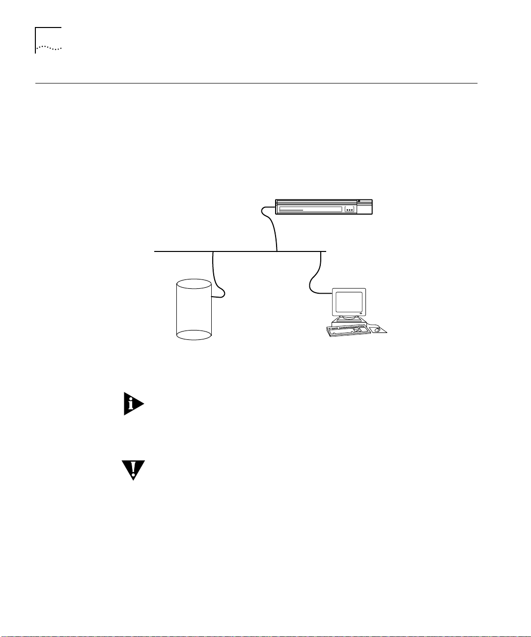
B-4 APPENDIX B: REMOTE SOFTWARE UP/DOWNLOADING PROCEDURES
Telnet This method allows you to telnet into the target AccessBuilder’s
command line user interface as a superuser and issue the "load"
command to perform the desired transfer function. Although you telnet
into the AccessBuilder, the load command uses TFTP as the transfer
mechanism (requires a TFTP server to be available for either the upload
or download functions). The IP address of the TFTP server and the
target AccessBuilder must be known, as well as the SuperUser
password for the AccessBuilder.
AccessBuilder
4000
SYSTEM STATUSSYSTEM STATUS
Remote Access Server
Target AccessBuilder
StatusActivity Power
TFTP Server
Work Station
on network
Figure B-2 Remote Download/Upload Using Telnet
The header file name selected dictates the action that occurs (direction
of flow). Refer to Table B-1 for filenames.
Telnet Procedures Be sure you have set up a TFTP server. Refer to Table B-1 for filenames.
CAUTION: Whenever an image or configuration file download transfer
occurs, the remote AccessBuilder suspends any user session in progress
and automatically resets upon completion, thus disconnecting any
active users. For this reason, maintenance downloads should be
announced to the system users well in advance of the event, and
scheduled at a time that minimizes network disruption.
1 Copy the files absrvr.cde, absrvr.hd0, absrvr.hd1, and absrvr.hd2 on the
AccessBuilder distribution diskette to the TFTP host's TFTP directory.
Page 59

Console Port B-5
2 Verify that the AccessBuilder IP address and default router address have
been properly configured (see TABM on-line help or the optional
AccessBuilder Software Configuration Guide).
3 If you are updating from software version 5.0 or above, use the Load
command followed by the desired filename, followed by the TFTP
server’s IP address. For example:
\> load absrvr 192.142.72.80
Where 192.142.72.80 is the IP address of the TFTP server.
The AccessBuilder server then resets and resumes normal operation.
The download/upload procedure is now complete.
In the event a TFTP image download fails, perform steps 4 through 8 of
the Console Port Download procedure (page B-9).
Console Port Download/upload operations may also be performed through the
AccessBuilder’s console port. Two methods may be used:
■ On-site, a local PC running a terminal emulator is attached to the
console port,
■ Remotely, the same as above but with modems in between.
This technique is based on using a PC with a terminal emulator (using
the Windows X-Modem file transfer protocol) to either directly connect
to the local AccessBuilder’s console port, or initiate a call into the
remote AccessBuilder 4000’s console port. Once connected to the
AccessBuilder’s command line interface, an appropriate transfer
command may be issued to perform the desired upload/download
function.
Page 60

B-6 APPENDIX B: REMOTE SOFTWARE UP/DOWNLOADING PROCEDURES
PC
Use null modem
cable here
PC
Telephone
Network
Remote Access Server
AccessBuilder 4000 Series
Use straigth-thru
cable here
Remote Access Server
AccessBuilderAccessBuilder
4000
SYSTEM STATUSSYSTEM STATUS
StatusActivity Power
AccessBuilderAccessBuilder
4000
SYSTEM STATUSSYSTEM STATUS
StatusActivity Power
Figure B-3 Remote Download/Upload Using The AccessBuilder Console Port
At the AccessBuilder 4000 remote site, you must have a modem
connected to the AccessBuilder 4000’s console port. Use a male DB-25
to male DB-25 null modem cable to connect the modem to the
AccessBuilder 4000’s console port.
If a dedicated phone line is not used, make arrangements to have an
available line connected to the modem. Be sure to obtain the phone
number of the line used.
Local PC . On your local PC you will need a terminal emulation
program capable of supporting the Windows X-Modem file transfer
protocol. The terminal emulator accessory supplied with Windows
provides this functionality. This function is also provided through TABM.
If you plan to download a new AccessBuilder 4000 server software
image, be sure the new server software image has been loaded onto
the local PC from the 3Com-provided AccessBuilder 4000 Software
distribution diskette.
Initial Setup General
1 Connect a PC directly to the console port using a straight-through
cable.
or
2 Connect a modem to the console port using a null modem cable. Then
have a PC connected to a modem dial in to the console port.
Page 61

Console Port B-7
For the PC (terminal emulator), the setup for either direct or modem
connection is the same:
■ 9600 baud
■ 8 data bits, 1 stop bit, no parity
■ hardware flow control
■ X-Modem binary file transfer
For the modem connected to the PC, use the following configuration:
■ 9600 baud
■ hardware flow control
For the modem to the AccessBuilder console port, use the following
configuration:
■ 9600 baud
■ autoanswer
■ disable results code
■ ignore DTR
■ no flow control
PC Terminal Emulator Setup
At your PC, it is first necessary to setup the telephone number of the
remote AccessBuilder site, the modem "AT" command string that
initializes your modem, and the communications parameters of your
Windows terminal emulator accessory. Once established, this
information can be saved in a specified file for convenience.
This procedure can be done either directly from Windows or from the
Transcend AccessBuilder Manager application, which automatically
loads the Windows Terminal accessory. Whichever way you go, perform
the initial setup:
1 From Windows, double-click on the Accessories icon, then double-click
on the Terminal icon.
From TABM, choose the Remote Download Image selection in the
System Dialog Menu.
2 Go to the Settings pull-down menu and select Communications. Set
the Baud Rate to 9600, the Flow Control to Hardware, and the COM
port to the port to which your PC modem is connected.
Page 62

B-8 APPENDIX B: REMOTE SOFTWARE UP/DOWNLOADING PROCEDURES
3 Next, go to the Modem selection and enter the "AT" string required to
initialize the modem you have connected to your COM port.
4 Select the Telephone Number selection and enter the phone number
of the modem connected to the remote AccessBuilder.
5 At this point this information should be saved in a filename related to
the target remote AccessBuilder.
Console Port
Procedures
AccessBuilder 4000 Software Image Download Procedure
This procedure is used to copy a new version of AccessBuilder system
software image from the local PC into the flash memory of a remote
AccessBuilder without affecting the existing configuration. Note that
the server is automatically reset upon successful completion of the
image download.
CAUTION: Whenever an image or configuration file download
transfer occurs, the remote AccessBuilder suspends any user session in
progress and automatically resets upon completion, thus disconnecting
any active users. For this reason, maintenance downloads should be
announced to the system users well in advance of the event, and
scheduled at a time that minimizes network disruption.
Downloading the software through the console port will take
approximately 25 minutes to perform.
1 From the local PC running either the TABM application or the Windows
terminal emulator, dial into the modem connected to the
AccessBuilder’s console port.
2 Navigate through the login prompts by entering the SU (SuperUser)
command and your password as described in the following example:
Login: su
Password:; type in your password here
3 W ithin the UI, type the following command to enter the nindy mode:
\> nindy;system will enter the nindy mode
4 W ithin nindy, type the following commands:
-> nh;start nindy header
-> rs ;reset the system
Page 63

Console Port B-9
If you are doing this via a modem you have to redial to the
AccessBuilder unit if the modem on the console port was not set to
ignore DTR.
5 After system reset, type the following command to start xmodem
downloading in nindy:
C> do;start xmodem downloading
6 Insert the “AccessBuilder server software” diskette (to be download)
into the PC. Within the Windows Terminal emulator, click the “Send
Binary File...” item under the “Transfer” menu, and then select the file
(usually, it is a file called “
absrvr.cf0”. At this time a progress meter
appears to show the status of downloading.
7 After the progress meter disappears, the xmodem downloading is
completed if you get no error messages reported; otherwise, you will
need to repeat steps 4 and 5. If not successful after several repeats,
type the commands “
ch” and “rs” (as in step 7) to reset the system to
its original state.
8 Press the “Enter” key to get the “C>” prompt in nindy, then type the
following commands to complete upgrading:
C> ef;erase flash rom
C> uf;update flash rom
C> ch;clear header
C> rs;restart
The system will reset and the AccessBuilder server resumes normal
operation.
The software upgrade is now complete. If you have any problems call
3Com technical support at 1-800-NET-3COM.
Page 64

B-10 APPENDIX B: REMOTE SOFTWARE UP/DOWNLOADING PROCEDURES
Page 65

C
INSTALLING I/O CARDS
This appendix describes how to install the WAN interface I/O cards, the
cards should be installed before you install the server on your network.
I/O cards provide an interface between outside users and the network.
Physically, each of the I/O card ports is connected to a modem or a
switched or dedicated digital line for connection to the outside world.
Three types of I/O cards are available:
■ asynchronous cards for dial-up telephone line connections (three
models)
■ ISDN cards (U and S/T interfaces)
■ a synchronous card for connections to high-speed leased lines.
Descriptions of I/O Cards
Asynchronous I/O
Cards
This section provides a brief description of each of the available I/O
cards.
The asynchronous cards are available in three versions:
■ A 4-port asynchronous card has four RJ-45 connector jacks with
port status LEDs,
■ an 8-port asynchronous card that has eight RJ-45 connector jacks
and supports operation to 57,600 bps,
■ an 8-port high speed asynchronous card that has eight RJ-45
connector jacks and supports operation to 115,400 bps.
Figure C-1 shows the asynchronous I/O cards and the external ports on
the back panel for the 4-port and 8-port asynchronous cards (since the
8-port cards look similar, only one is shown).
Page 66
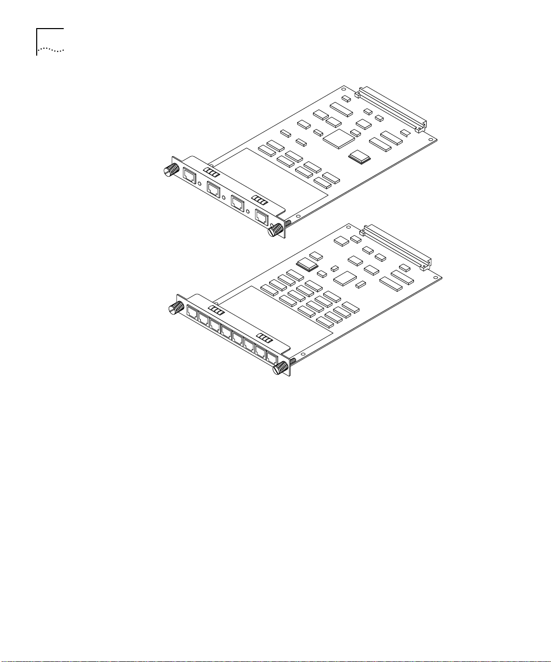
C-2 APPENDIX C: INSTALLING I/O CARDS
Port 4
Port 8
Port 1
Synchronous I/O
Card
Port 1
Figure C-1 Asynchronous I/O Card Major Components and Ports
The synchronous card provides a V.35, RS-449, RS-232, or X.21
synchronous interface that can be used to interconnect the
AccessBuilder to a synchronous modem for digital lease line
connections.
Figure C-2 shows the major components of the synchronous card and
the external port on the back panel.
Page 67

Descriptions of I/O Cards C-3
Figure C-2 Synchronous I/O Card Major Components and Port
ISDN Cards The S/T and U AccessBuilder ISDN adapter cards each have four ports.
The U version, with an integrated NT1, is designed for direct
connection to ISDN lines in North America, while the S/T version is
designed for use in Europe and Japan. The S/T card connects to a
network terminator unit, which in turn, connects directly to the ISDN
line.
Three status indicator are located to the left of each port (because both
cards look similar, only one is shown)
Figure C-3 ISDN Basic Rate Interface (BRI) Module
Page 68

C-4 APPENDIX C: INSTALLING I/O CARDS
Installation Overview
Installation Procedure
All of the I/O cards are installed in either Slot 1 or Slot 2, below the
main processor board. The installation procedures for all cards is
basically the same and involves these steps:
■ Removing the card from its protective bag
■ Removing the filler panel over the desired card slot
■ Inserting the card into the slot so it connects with the backplane
■ Fastening the card to the backplane
■ Connecting the I/O card connections to the network or modem(s)
To install an I/O card:
1 Remove the card from its antistatic bag.
Do not touch pins, leads, or solder connections on the card. Handle the
card by the edges only.
2 Inspect the card for shipping damage.
If you find any damage, contact the shipping company to file a report.
If the I/O card must be returned to the factory, ship it in the original
shipping carton and antistatic bag. If the original carton was damaged
in shipment, repack the card in a carton that provides equivalent
protection.
3 If you have not already done so, write down the serial number shown
on the component side of the card.
You will need this information if you have to contact your supplier for a
replacement.
4 Select a slot for the I/O card, either slot 1 or 2.
5 Remove the face plate from the slot you have selected.
To remove the plate, loosen the captive screws and slide the face plate
away from the slot, as shown in Figure C-4.
Page 69

Installation Procedure C-5
110-240 VAC
50-60 Hz 1A
UTP
AUI
ETHERNET
BNC
BNC/AUI/TPE
CONSOLE
SLOT 2
SLOT 1
Figure C-4 Removing a Face Plate
Only remove the face plate from the I/O slot you are planning to use.
All unused I/O slots must have the face plate installed to maintain
proper cooling of the unit and regulatory compliance. Failure to cover
open slots can result in overheating and void the warranty.
6 Insert the I/O card into the uncovered I/O slot as follows:
a With the connector end toward the backplane and the card panel
facing you, grasp the left and right sides of the back panel and fit
the card into the card guides in the I/O slot opening.
The card fits in only one way, the labels on the back panel should
be right side up.
b Slide the card into the chassis until the card engages the backplane
connectors.
c Secure the I/O card in the slot by tightening the captive screws
shown in Figure C-5.
Page 70

C-6 APPENDIX C: INSTALLING I/O CARDS
110-240 VAC
50-60 Hz 1A
UTP
AUI
ETHERNET
BNC
BNC/AUI/TPE
CONSOLE
SLOT 2
SLOT 1
Figure C-5 Fastening I/O Card Captive Screws
A solid connection of the I/O card to the chassis is required for proper
operation, but the screws should not be used to force the card into
place.
CAUTION: If the resistance is too great as you slide the card into
position, it may mean that the card and backplane connectors are not
aligned. Forcing the card can cause damage. If necessary, remove and
reinsert the card, making sure the card is properly aligned in the card
guides.
7 Check that the face of the newly inserted card is flush with the
AccessBuilder chassis and is aligned with the adjacent slot.
Once the card is inserted and secured in the slot, you are ready to
attach the external cables.
Attaching I/O Cables
Asynchronous Cards To cable an asynchronous card:
Page 71

Attaching I/O Cables C-7
1 Connect the RJ-45 end of the cable to the asynchronous port on the
I/O card, then attach the DB-25 end of the cable to the modem as
shown in Figure C-6.
110-240 VAC
50-60 Hz 1A
UTP
AUI
ETHERNET
BNC
BNC/AUI/TPE
CONSOLE
SLOT 2
SLOT 1
Figure C-6 Connecting a Cable to an Asynchronous I/O Card
Synchronous Card 3Com makes four types of cables to accommodate your network
requirements. Each cable has a DB-50 connector that plugs into the
synchronous I/O card, and a synchronous connector at the other end
for connection to the network.
The four cable types are shown in Table C-1.
Table C-1 Types of Synchronous Cables
Cable Type Description
V.35 cable The network connector is a male 34-pin V.35 block
RS-449 cable The network connector is a male 37-pin RS-449 connector
RS-232 cable The network connector is a male 25-pin RS-232 connector
connector for access to modem or data service unit
(CSU/DSU) interfaces.
for access to modem or data service unit (CSU/DSU)
interfaces.
for access to modem or data service unit (CSU/DSU)
interfaces.
Page 72

C-8 APPENDIX C: INSTALLING I/O CARDS
Table C-1 Types of Synchronous Cables
Cable Type Description
X.21 cable The network connector is a male 15-pin X.21 connector for
If you have mistakenly received the wrong synchronous cable with your
I/O card, contact your supplier for a replacement.
To cable a synchronous card:
1 Connect the DB-50 end of the cable to the synchronous port on the
I/O card, then attach the other end to the CSU/DSU or modem
connector, as shown in Figure C-7.
access to modem or data service unit (CSU/DSU) interfaces.
110-240 VAC
50-60 Hz 1A
UTP
AUI
ETHERNET
BNC
BNC/AUI/TPE
CONSOLE
SLOT 2
SLOT 1
Figure C-7 Connecting a Cable to a Synchronous I/O Card
ISDN Card To connect either the U card to the ISDN line, or the S/T card to the
NT1, (which in turn connects to the ISDN line), use the RJ-45 to RJ-45
cables 3Com supplies with the each card.
Page 73

Attaching I/O Cables C-9
110-240 VAC
50-60 Hz 1A
SLOT 2
Figure C-8 ISDN Card Connection
CONSOLE
BNC/AUI/TPE
ETHERNET
BNC
UTP
AUI
SLOT 1
Page 74

C-10 APPENDIX C: INSTALLING I/O CARDS
Page 75

CONFIGURATION WORKSHEETS
D
This Appendix provides sample configuration worksheets as a
convenience in assisting you to successfully configure the TABM
workstation, the AccessBuilder 4000 servers, and the remote user’s
AccessBuilder Remote Access Client software. This information can then
be transferred to the screens that appear during the configuration
procedure and may be photocopied and filled in for each workstation,
server, or remote user.
Instructions TABM Workstation Worksheets
Photocopy a page for each PC workstation on which you plan to install
TABM. Once the information has been defined, it can be used as a
ready reference when you perform the actual TABM installation.
AccessBuilder Server Worksheets
Photocopy a page for each server you plan to configure or maintain
using TABM. Once completed, the form can be used as a ready
reference when you perform the actual configuration using TABM. You
may wish to retain the form (in a secure place, of course) as a record of
specific AccessBuilder configuration details.
AccessBuilder Client Worksheets
Once each applicable page or screen has been completed for a specific
user, it may be mailed, faxed, or otherwise communicated to the
remote access user for use during the AccessBuilder Client
configuration procedure (PC-based users only). You may also wish to
keep a copy of the completed form as a record of that user’s
configuration.
Refer to the AccessBuilder Remote Client on-line help for details on
specific fields within each screen.
Page 76

D-2 APPENDIX D: CONFIGURATION WORKSHEETS
TABM Workstation on IP Network
IP Server Address/Name Server Location
1
2
3
4
5
6
7
8
9
10
11
12
13
14
15
Workstation (PC running TABM) IP Address:
What is the TABM password (default = admin)?
What are the directory paths on this workstation for the following?
Where TABM resides
TFTP Server (see Note 1)
Ping (or equivalent -- see Note 2)
Telnet (or equivalent-- see Note 2)
Note 1: If no directory is defined for a TFTP server, press Return to proceed.
Note 2: Optional in your TCP/IP stack (not required for TABM operation).
AccessBuilders to be managed from this TABM PC (must be on the
same Ethernet segment as this workstation -- see TABM on-line help
for information on managing AccessBuilders on different subnets):
Server SU
Password
Page 77

TABM Workstation on IPX Network D-3
TABM Workstation on IPX Network
IPX Server Name Server Location
1
2
3
4
5
6
7
8
9
10
11
12
13
14
15
Workstation (PC running TABM) IPX Address:
What is the TABM password (default = admin)?
AccessBuilders to be managed from this TABM PC:
Server SU
Password
Page 78

D-4 APPENDIX D: CONFIGURATION WORKSHEETS
AccessBuilder Server
General Information
Server MAC Address
Server Physical Location
Server Name
Super User Password
Network Security System Type
Sign-on Greeting Message
Login Options: Normal Disable Login No Password
Asynchronous Port Setup
Port Modem Speed Compression Data Type
1
2
3
4
5
6
7
8
9
10
11
12
13
14
15
16
Console 9600 No N/A
Page 79

AccessBuilder Server D-5
ISDN Information
Interface U S/T Switch Type ATT5ESS NI1 DMS100 INS64 VN3 NET3
Point-to-Point (If yes, no SPIDs or RNs required in North America) Yes No
SPID Numbers
Directory Number
Rotary/Hunt Group Number (if used)
Slot 1
Ports
Port 1, Ch 1
Port 1, Ch 2
Port 2, Ch 1
Port 2, Ch 2
Port 3, Ch 1
Port 3, Ch 2
Port 4, Ch 1
Port 4, Ch 2
Slot 2
Ports
Port 1, Ch 1
Port 1, Ch 2
Port 2, Ch 1
Port 2, Ch 2
Port 3, Ch 1
Port 3, Ch 2
Port 4, Ch 1
Port 4, Ch 2
Directory Number SPID Router/Auto
Directory Number SPID Router/Auto
V.120
or raw
V.120
or raw
Page 80

D-6 APPENDIX D: CONFIGURATION WORKSHEETS
IP Network Information
Server IP Address
Server Net Mask
Default Router IP Address
Telnet Admin Port (default = 3000)
Dial-out Enabled Yes No
Remarks
IPX Network Information
Local IPX Network Address
Ethernet Data Link Type 802.3 802.2 Ethernet II SNAP Autolearn
Remarks
AppleTalk Network Information
Dial-in Zone Name
(must be an existing zone name on the network)
Remarks
Page 81

User Table D-7
User Table
Users assign to AccessBuilder Name
User Name Password Callback Number* Privilege
Remarks Access Type
(Auto or ARA 1.0**)
512 users maximum on the AccessBuilder 4000
*Callback is only supported when the remote user is running the AccessBuilder Remote Client software.
**ARA 1.0 remote users must be assigned to a dedicated ARA 1.0 port.
Page 82

D-8 APPENDIX D: CONFIGURATION WORKSHEETS
Remote Client
Remote User Name
Date
Location
PC Type
COM Port UART Type
COM Port Used for Remote Access
Modem Type and Speed
Client NOS
Client Telephone Number
Callback Number
Client Telephone Number
Additional Phone Book Numbers
Remarks
Page 83

E
TECHNICAL SUPPORT
3Com provides easy access to technical support information through a
variety of services. This appendix describes these services.
Information contained in this appendix is correct at time of
publication. For the very latest, we recommend that you access 3Com
Corporation’s World Wide Web site as described below.
Online Technical Services
World Wide Web Site Access the latest networking information on 3Com Corporation’s World
3Com Bulletin Board
Service
3Com offers worldwide product support 24 hours a day, 7 days a
week, through the following online systems:
■ World Wide Web site
■ 3Com Bulletin Board Service (3ComBBS)
■ 3ComFacts
■ 3ComForum on CompuServe
Wide Web site by entering our URL into your Internet browser:
http://www.3Com.com/
This service features news and information about 3Com products,
customer service and support, 3Com Corporation’s latest news releases,
NetAge Magazine, and more.
3ComBBS contains patches, software, and drivers for all 3Com
products, as well as technical articles. This service is available via
modem or ISDN 24 hours a day, 7 days a week.
Access by Analog Modem
To reach the service by modem, set your modem to 8 data bits,
no parity, and 1 stop bit. Call the telephone number nearest you:
SM
automated fax service
®
online service
Page 84

E-2 APPENDIX E: TECHNICAL SUPPORT
Country Data Rate Telephone Number
Australia up to 14400 bps 61 2 9955 2073
Brazil up to 14400 bps 55 11 547 9666
France up to 14400 bps 33 1 6986 6954
Germany up to 28800 bps 4989 62732 188
Hong Kong up to 14400 bps 852 2537 5608
Italy (fee required) up to 14400 bps 39 2 27300680
Japan up to 14400 bps 81 3 3345 7266
Mexico up to 28800 bps 52 5 520 7853
P. R. of China up to 14400 bps 86 10 684 92351
Singapore up to 14400 bps 65 534 5693
Taiwan up to 14400 bps 886 2 377 5840
U.K. up to 28800 bps 44 1442 438278
U.S.A. up to 28800 bps 1 408 980 8204
Access by Digital Modem
ISDN users can dial in to 3ComBBS using a digital modem for fast
access up to 56 Kbps. To access 3ComBBS using ISDN, use the
following number:
3ComFacts
Automated Fax
Service
408 654 2703
SM
3Com Corporation’s interactive fax service, 3ComFacts, provides data
sheets, technical articles, diagrams, and troubleshooting instructions on
3Com products 24 hours a day, 7 days a week.
Call 3ComFacts using your Touch-Tone telephone using one of these
international access numbers:
Country Telephone Number
Hong Kong 852 2537 5610
U.K. 44 1442 278279
U.S.A. 1 408 727 7021
Local access numbers are available within the following countries:
Page 85

Support from Your Network Supplier E-3
3ComForum on
CompuServe
®
Online
Service
Telephone
Country
Australia 1 800 123853 Netherlands 06 0228049
Belgium 0800 71279 Norway 800 11062
Denmark 800 17319 Portugal 0505 442 607
Finland 98 001 4444 Russia (Moscow only) 956 0815
France 05 90 81 58 Spain 900 964 445
Germany 0130 81 80 63 Sweden 020 792954
Italy 1678 99085 U.K. 0800 626403
Number
Country
Telephone
Number
3ComForum is a CompuServe-based service containing patches,
software, drivers, and technical articles about all 3Com products, as
well as a messaging section for peer support. To use 3ComForum, you
need a CompuServe account.
To use 3ComForum:
1 Log on to CompuServe.
2 Type
go threecom
3 Press [Return] to see the 3ComForum main menu.
Support from Your Network Supplier
If additional assistance is required, contact your network supplier.
Many suppliers are authorized 3Com service partners who are qualified
to provide a variety of services, including network planning, installation,
hardware maintenance, application training, and support services.
When you contact your network supplier for assistance, have the
following information ready:
■ Diagnostic error messages
■ A list of system hardware and software, including revision levels
■ Details about recent configuration changes, if applicable
If you are unable to contact your network supplier, see the following
section on how to contact 3Com.
Page 86

E-4 APPENDIX E: TECHNICAL SUPPORT
Support from 3Com If you are unable to receive support from your network supplier,
technical support contracts are available from 3Com.
Contact your local 3Com sales office to find your authorized service
provider using one of these numbers:
Regional Sales Office Telephone Number Regional Sales Office Telephone Number
3Com Corporation
U.S.
3Com ANZA
East
West
3Com Asia Limited
China
Hong Kong
India
Indonesia
Korea
Malaysia
Singapore
Taiwan
Thailand
3Com Benelux B.V.
Belgium
Netherlands
3Com Canada
Calgary
Montreal
Ottawa
Toronto
Vancouver
3Com France
3Com GmbH
Austria
Czech and Slovak Republics
Germany
Hungary
Poland
Switzerland
800 NET 3Com or
1 408 764 5000
61 2 9937 5000
61 3 9866 8022
86 10 68492 568 (Beijing)
86 21 6374 0220 Ext 6115
(Shanghai)
852 2501 1111
91 11 644 3974
62 21 523 9181
82 2 319 4711
60 3 732 7910
65 538 9368
886 2 377 5850
662 231 8151 4
32 725 0202
31 30 6029700
403 265 3266
514 683 3266
613 566 7055
416 498 3266
604 434 3266
33 1 69 86 68 00
43 1 5134323
42 2 21845 800
49 30 3498790 (Berlin)
49 89 627320 (Munich)
36 1 250 83 41
48 22 6451351
41 31 996 14 14
3Com Ireland
3Com Japan
3Com Latin America
Argentina
Brazil
Chile
Colombia
Mexico
Peru
Venezuela
3Com Mediterraneo
Italy
3Com Middle East
3Com Nordic AB
Denmark
Finland
Norway
Sweden
3Com Russia
3Com South Africa
3Com UK Limited
353 1 820 7077
81 3 3345 7251
54 1 312 3266
55 11 546 0869
56 2 633 9242
57 1 629 4110
52 5 520 7841
51 1 221 5399
58 2 953 8122
39 2 253011 (Milan)
39 6 5279941 (Rome)
971 4 349049
45 39 27 85 00
358 0 435 420 67
47 22 18 40 03
46 8 632 56 00
007 095 2580940
27 11 807 4397
44 131 2478558 (Edinburgh)
44 161 8737717 (Manchester)
44 1628 897000 (Marlow)
Page 87

Returning Products for Repair E-5
Returning Products for Repair
02/06/97
Before you send a product directly to 3Com for repair, you must first be
obtain a Return Materials Authorization (RMA) number. Products sent
to 3Com without RMA numbers will be returned to the sender
unopened, at the sender’s expense.
To obtain an RMA number, call or fax:
Country Telephone Number Fax Number
U.S.A. and Canada 1 800 876 3266, option 2 408 764 7120
Latin America 1 408 326 7801 408 764 7120
Europe, South Africa and
Middle East
Outside Europe, U.S.A.,
and Canada
44 1442 438125 44 1442 435822
1 408 326 7804 1 408 764 7120
Page 88

E-6 APPENDIX E: TECHNICAL SUPPORT
Page 89

3Com Corporation LIMITED WARRANTY
HARDWARE 3Com warrants its hardware products to be free from defects in workmanship and materials, under
normal use and service, for the following lengths of time from the date of purchase from 3Com or its
Authorized Reseller:
Network adapters Lifetime
Other hardware products (unless otherwise specified above) 1 year
Spare parts and spares kits 90 days
If a product does not operate as warranted above during the applicable warranty period, 3Com shall, at
its option and expense, repair the defective product or part, deliver to Customer an equivalent product or
part to replace the defective item, or refund to Customer the purchase price paid for the defective
product. All products that are replaced will become the property of 3Com. Replacement products may be
new or reconditioned. Any replaced or repaired product or part has a ninety (90) day warranty or the
remainder of the initial warranty period, whichever is longer.
3Com shall not be responsible for any software, firmware, information, or memory data of Customer
contained in, stored on, or integrated with any products returned to 3Com for repair, whether under
warranty or not.
SOFTWARE 3Com warrants that the software programs licensed from it will perform in substantial conformance to the
program specifications therefor for a period of ninety (90) days from the date of purchase from 3Com or
its Authorized Reseller. 3Com warrants the media containing software against failure during the warranty
period. No updates are provided. 3Com’s sole obligation with respect to this express warranty shall be (at
3Com’s discretion) to refund the purchase price paid by Customer for any defective software products, or
to replace any defective media with software which substantially conforms to 3Com’s applicable published
specifications. Customer assumes responsibility for the selection of the appropriate applications program
and associated reference materials. 3Com makes no warranty or representation that its software products
will work in combination with any hardware or applications software products provided by third-parties,
that the operation of the software products will be uninterrupted or error free, or that all defects in the
software products will be corrected. For any third-party products listed in the 3Com software product
documentation or specifications as being compatible, 3Com will make reasonable efforts to provide
compatibility, except where the noncompatibility is caused by a “bug” or defect in the third-party’s
product.
STANDARD WARRANTY
S
ERVICE
Standard warranty service for hardware products may be obtained by delivering the defective product,
accompanied by a copy of the dated proof of purchase, to 3Com’s Corporate Service Center or to an
Authorized 3Com Service Center during the applicable warranty period. Standard warranty service for
software products may be obtained by telephoning 3Com’s Corporate Service Center or an Authorized
3Com Service Center, within the warranty period. Products returned to 3Com’s Corporate Service Center
must be pre-authorized by 3Com with a Return Material Authorization (RMA) number marked on the
outside of the package, and sent prepaid, insured, and packaged appropriately for safe shipment. The
repaired or replaced item will be shipped to Customer, at 3Com’s expense, not later than thirty (30) days
after receipt of the defective product by 3Com.
WARRANTIES EXCLUSIVE IF A 3COM PRODUCT DOES NOT OPERATE AS WARRANTED ABOVE, CUSTOMER’S SOLE REMEDY FOR
BREACH OF THAT WARRANTY SHALL BE REPAIR, REPLACEMENT, OR REFUND OF THE PURCHASE PRICE
PAID, AT 3COM’S OPTION. TO THE FULL EXTENT ALLOWED BY LAW, THE FOREGOING WARRANTIES AND
REMEDIES ARE EXCLUSIVE AND ARE IN LIEU OF ALL OTHER WARRANTIES, TERMS, OR CONDITIONS,
EXPRESS OR IMPLIED, EITHER IN FACT OR BY OPERATION OF LAW, STATUTORY OR OTHERWISE,
INCLUDING WARRANTIES, TERMS, OR CONDITIONS OF MERCHANTABILITY, FITNESS FOR A PARTICULAR
PURPOSE, AND SATISFACTORY QUALITY. 3COM NEITHER ASSUMES NOR AUTHORIZES ANY OTHER
PERSON TO ASSUME FOR IT ANY OTHER LIABILITY IN CONNECTION WITH THE SALE, INSTALLATION,
MAINTENANCE, OR USE OF ITS PRODUCTS.
Page 90

3COM SHALL NOT BE LIABLE UNDER THIS WARRANTY IF ITS TESTING AND EXAMINATION DISCLOSE
THAT THE ALLEGED DEFECT IN THE PRODUCT DOES NOT EXIST OR WAS CAUSED BY CUSTOMER’S OR
ANY THIRD PERSON’S MISUSE, NEGLECT, IMPROPER INSTALLATION OR TESTING, UNAUTHORIZED
ATTEMPTS TO REPAIR OR MODIFY, OR ANY OTHER CAUSE BEYOND THE RANGE OF THE INTENDED USE,
OR BY ACCIDENT, FIRE, LIGHTNING, OR OTHER HAZARD.
LIMITATION OF LIABILITY TO THE FULL EXTENT ALLOWED BY LAW, 3COM ALSO EXCLUDES FOR ITSELF AND ITS SUPPLIERS ANY
LIABILITY, WHETHER BASED IN CONTRACT OR TORT (INCLUDING NEGLIGENCE), FOR INCIDENTAL,
CONSEQUENTIAL, INDIRECT, SPECIAL, OR PUNITIVE DAMAGES OF ANY KIND, OR FOR LOSS OF REVENUE
OR PROFITS, LOSS OF BUSINESS, LOSS OF INFORMATION OR DATA, OR OTHER FINANCIAL LOSS ARISING
OUT OF OR IN CONNECTION WITH THE SALE, INSTALLATION, MAINTENANCE, USE, PERFORMANCE,
FAILURE, OR INTERRUPTION OF ITS PRODUCTS, EVEN IF 3COM OR ITS AUTHORIZED RESELLER HAS BEEN
ADVISED OF THE POSSIBILITY OF SUCH DAMAGES, AND LIMITS ITS LIABILITY TO REPAIR, REPLACEMENT,
OR REFUND OF THE PURCHASE PRICE PAID, AT 3COM’S OPTION. THIS DISCLAIMER OF LIABILITY FOR
DAMAGES WILL NOT BE AFFECTED IF ANY REMEDY PROVIDED HEREIN SHALL FAIL OF ITS ESSENTIAL
PURPOSE.
Some countries, states, or provinces do not allow the exclusion or limitation of implied warranties or the
limitation of incidental or consequential damages for certain products supplied to consumers or the
limitation for personal injury, so the above limitations and exclusions may be limited in their application to
you. This warranty gives you specific legal rights which may vary depending on local law.
GOVERNING LAW This Limited Warranty shall be governed by the laws of the state of California.
3Com Corporation, 5400 Bayfront Plaza, Santa Clara, CA 95052-8145 (408) 764-5000
9/1/96
 Loading...