

Page 1

SuperStack® II
®
Switch 9100
User Guide
http://www.3com.com/
Part No. DUA1770-5AAA01
Published January 2000
Page 2

3Com Corporation
5400 Bayfront Plaza
Santa Clara, California
95052-8145
Copyright © 1999, 3Com Technologies. All rights reserved. No part of this documentation may be reproduced
in any form or by any means or used to make any derivative work (such as translation, transformation, or
adaptation) without written permission from 3Com Technologies.
3Com Technologies reserves the right to revise this documentation and to make changes in content from time
to time without obligation on the part of 3Com Technologies to provide notification of such revision or
change.
3Com Technologies provides this documentation without warranty, term, or condition of any kind, either
implied or expressed, including, but not limited to, the implied warranties, terms or conditions of
merchantability, satisfactory quality, and fitness for a particular purpose. 3Com may make improvements or
changes in the product(s) and/or the program(s) described in this documentation at any time.
If there is any software on removable media described in this documentation, it is furnished under a license
agreement included with the product as a separate document, in the hard copy documentation, or on the
removable media in a directory file named LICENSE.TXT or !LICENSE.TXT. If you are unable to locate a copy,
please contact 3Com and a copy will be provided to you.
UNITED STATES GOVERNMENT LEGEND
If you are a United States government agency, then this documentation and the software described herein are
provided to you subject to the following:
All technical data and computer software are commercial in nature and developed solely at private expense.
Software is delivered as “Commercial Computer Software” as defined in DFARS 252.227-7014 (June 1995) or
as a “commercial item” as defined in FAR 2.101(a) and as such is p rovided with only such rights as are
provided in 3Com’s standard commercial license for the Software. Technical data is provided with limited rights
only as provided in DFAR 252.227-7015 (Nov 1995) or FAR 52.227-14 (June 1987), whichever is applicable.
You agree not to remove or deface any portion of any legend provided on any licensed program or
documentation contained in, or delivered to you in conjunction with, this User Guide.
Portions of this documentation are reproduced in whole or in part with permission from (as appropriate).
Unless otherwise indicated, 3Com registered trademarks are registered in the United States and may or may not
be registered in other countries.
3Com, the 3Com logo, EtherLink, and 3ComFacts are registered trademarks of 3Com Corporation.
Intel and Pentium are registered trademarks of Intel Corporation. IBM is a registered trademark of International
Business Machines Corporation. Microsoft, MS-DOS, Windows, and Windows NT are registered trademarks of
Microsoft Corporation. UNIX is a registered tra demark in the United States and othe r countries, li censed
exclusively through X/Open Company, Ltd. Netscape Navigator is a registered trademark of Netscape
Communications. JavaScript is a trademark of Sun Microsystems Corporation. CompuServe is a registered
trademark of CompuServe, Inc.
All other company and product names may be trademarks of the respective companies with which they are
associated.
Page 3

C
ONTENTS
BOUT THIS GUIDE
A
Terminology 11
Conventions 12
Related Documentation 13
Year 2000 Compliance 13
Product Registration 13
WITCH
1
S
About the Switch 9100 15
Summary of Features 15
Network Configuration Example 18
Switch 9100 Front View 20
Switch 9100 Rear View 22
Factory Defaults 23
9100 O
Port Connections 16
Full-duplex 17
Load Sharing 17
Switch Operation 17
Virtual LANs (VLANs) 17
Spanning Tree Protocol (STP) 18
Quality of Service (QoS) 18
Ports 20
LEDs 21
Power Sockets 23
Serial Number 23
MAC Address 23
Console Port 23
Reset Button 23
VERVIEW
Page 4

NSTALLATION AND SETUP
2
I
Determining the Switch 9100 Location 25
Configuration Rules for Ethernet 26
Installing the Switch 9100 26
Rack Mounting 26
Free-Standing 27
Stacking the Switch and Other Devices 28
Connecting Equipment to the Console Port 28
Powering-up the Switch 30
Checking the Installation 30
Power On Self-Test (POST) 30
Logging on for the First Time 31
3
CCESSING THE SWITCH
A
Understanding the Command Syntax 34
Syntax Helper 34
Command Completion with Syntax Helper 34
Abbreviated Syntax 35
Command Shortcuts 35
Switch 9100 Numerical Ranges 35
Names 35
Symbols 36
Line-Editing Keys 37
Command History 37
Common Commands 37
Configuring Management Access 40
Default Accounts 41
Changing the Default Password 41
Creating a Management Account 42
Viewing Accounts 42
Deleting an Account 43
Methods of Managing the Switch 9100 43
Using the Console Interface 43
Creating an Access Profile 44
Access Profile Rules 45
Access Profile Example 45
Using Telnet 46
Page 5

Connecting to Another Host Using Telnet 46
Configuring Switch IP Parameters 46
Using a BOOTP Server 46
Manually Configuring the IP Settings 47
Disconnecting a Telnet Session 49
Disabling Telnet Access 49
IP Host Configuration Commands 50
Using the Web Interface 50
Disabling Web Access 51
Using SNMP 51
Accessing Switch Agents 51
Supported MIBs 51
Configuring SNMP Settings 52
Displaying SNMP Settings 53
Resetting and Disabling SNMP 54
Checking Basic Connectivity 54
Configuring Switch 9100 Port Speed and Duplex Setting 55
100/1000BASE-T Ports 55
1000BASE-SX Ports 55
Enabling Autonegotiation 55
Flow Control 56
Switch 9100 Port Commands 56
Load Sharing on the Switch 9100 58
Load Sharing Algorithms 58
Configuring Switch 9100 Load Sharing 59
Load-Sharing Example 59
Verifying the Load Sharing Configuration 60
Switch 9100 Port-Mirroring 60
Port-Mirroring Commands 61
Switch 9100 Port-Mirroring Example 61
4
IRTUAL
V
Overview of Virtual LANs 63
Types of VLANs 66
LANS (VLANS)
Benefits 63
IGMP Snooping 64
Port-Based VLANs 66
Page 6

Spanning Switches with Port-Based VLANs 67
Tagged VLANs 69
Uses of Tagged VLANs 70
Assigning a VLAN Tag 70
Mixing Port-Based and Tagged VLANs 72
Protocol-Based VLANs 72
Predefined Protocol Filters 73
Defining Protocol Filters 74
Deleting a Protocol Filter 75
Precedence of Tagged Packets Over Protocol Filters 75
VLAN Names 75
Default VLAN 75
Configuring VLANs on the Switch 76
VLAN Configuration Examples 77
Displaying VLAN Settings 78
Deleting VLANs 79
ORWARDING DATABASE
5
F
Overview of the FDB 81
FDB Contents 81
FDB Entry Types 81
How FDB Entries Get Added 82
Associating a QoS Profile with an FDB Entry 82
Configuring FDB Entries 83
FDB Configuration Examples 83
Displaying FDB Entries 84
Removing FDB Entries 85
(FDB)
PANNING TREE PROTOCOL
6
S
Overview of the Spanning Tree Protocol 87
How STP Works 89
Initialization 89
Stabilization 90
Reconfiguration 90
Spanning Tree Domains 90
Defaults 91
STP Configurations 91
(STP)
Page 7

Configuring STP on the Switch 94
STP Configuration Example 96
Displaying STP Settings 96
Disabling and Resetting STP 97
7
UALITY OF SERVICE
Q
Overview of Quality of Service 99
Building Blocks 99
QoS Profiles 100
Modifying a QoS Profile 101
The Blackhole QoS Profile 102
Traffic Groupings and Creating a QoS Policy 102
MAC-Based Traffic Groupings 103
Permanent MAC addresses 103
Dynamic MAC Addresses 103
Blackhole 104
Broadcast/Unknown Rate Limiting 104
Verifying MAC-Based QoS Settings 104
Packet Groupings 104
802.1p Packets 105
Physical and Logical Groupings 105
Source Port 106
VLAN 106
Verifying Physical and Logical Groupings 106
Verifying Configuration and Performance 107
Displaying QoS Information 107
QoS Monitor 107
Modifying a QoS Policy 108
Configuring QoS 109
(QOS)
TATUS MONITORING AND STATISTICS
8
S
Status Monitoring 111
Port Statistics 113
Port Errors 114
Port Monitoring Display Keys 115
Logging 115
Local Logging 116
Page 8

Real-Time Display 117
Remote Logging 117
Logging Commands 118
RMON 119
About RMON 119
About the RMON Groups 120
Statistics 120
History 120
Alarms 120
Events 121
Benefits of RMON 121
Improving Efficiency 121
Allowing Proactive Management 121
Reducing the Traffic Load 121
RMON and the Switch 122
RMON Features of the Switch 122
Configuring RMON 123
Event Actions 123
10
9
SING THE WEB INTERFACE
U
Enabling and Disabling Web Access 125
Setting Up Your Browser 126
Accessing the Web Interface 126
Navigating the Web Interface 127
Ta s k F r a m e 1 2 7
Content Frame 128
Browser Controls 128
Status Messages 128
Standalone Buttons 128
Saving Changes 129
OFTWARE UPGRADE AND BOOT OPTIONS
S
Downloading a New Image 131
Rebooting the Switch 132
Saving Configuration Changes 132
Returning to Factory Defaults 133
Upgrading and Accessing BootROM 133
Page 9

Upgrading BootROM 133
Accessing the BootROM menu 133
Boot Option Commands 135
A
B
C
D
AFETY INFORMATION
S
Important Safety Information 138
Lithium Battery 140
L’information de Sécurité Importante 141
Batterie au lithium 143
Wichtige Sicherheitsinformationen 144
Europe 144
Lithiumbatterie 145
ECHNICAL SPECIFICATIONS
T
ROUBLESHOOTING
T
Port Configuration 152
VLANs 153
STP 155
ECHNICAL SUPPORT
T
Online Technical Services 157
World Wide Web Site 157
3Com Knowledgebase Web Services 157
3Com FTP Site 158
3Com Bulletin Board Service 158
Access by Analog Modem 158
Access by Digital Modem 159
3Com Facts Automated Fax Service 159
Support from Your Network Supplier 159
Support from 3Com 159
Returning Products for Repair 161
Page 10

LOSSARY
G
NDEX
I
NDEX OF COMMANDS
I
3COM C
EMC S
ORPORATION LIMITED WARRANTY
TATEMENTS
Page 11

A
BOUT
T
HIS
G
UIDE
Terminology
This guide describes the required information to install and configure the
SuperStack
This guide is intended for use by network administrators who are
responsible for installing and setting up network equipment. It assumes a
basic working knowledge of:
■
Local Area Networks (LANs)
Ethernet concepts
■
Ethernet switching and bridging concepts
■
■
Simple Network Management Protocol (SNMP)
If release notes are shipped with your product and the information there
differs from the information in this guide, follow the instructions in the
release notes.
Throughout this guide, the term Switch 9100 is used to refer to the
SuperStack II Switch 9100.
For definitions of other terms used in this guide, refer to the “
located at the end of the user guide.
The terms Forwarding Database and Switch Database are
interchangeable.
®
II Switch 9100 (3C17705).
Glossary,”
Most user guides and release notes are available in Adobe Acrobat
Reader Portable Document Format (PDF) or HTML on the 3Com
World Wide Web site:
http:/ /www.3com.com/
Page 12
12
A
BOUT THIS GUIDE
Conventions
Table 1 and Table 2 list conventions that are used throughout this guide.
Table 1
Icon Notice Type Description
Table 2
Convention Description
Screen displays
Commands
The words “enter”
and “type”
Keyboard key names If you must press two or more keys simultaneously, the key
Words in
Notice Icons
Information note Information that describes important features or
instructions
Caution Information that alerts you to potential loss of data or
potential damage to an application, system, or device
Warning Information that alerts you to potential personal injury
Text Conventions
This typeface represents information as it appears on the
screen.
The word “command” means that you must enter the
command exactly as shown and then press Return or Enter.
Commands appear in bold. Example:
To remove the IP address, enter the following command:
SETDefault !0 -IP NETaddr = 0.0.0.0
When you see the word “enter” in this guide, you must type
something, and then press Return or Enter. Do not press
Return or Enter when an instruction simply says “type.”
names are linked with a plus sign (+). Example:
Press Ctrl+Alt+Del
italics
Italics are used to:
Emphasize a point.
■
Denote a new term at the place where it is defined in the
■
text.
Identify menu names, menu commands, and software
■
button names. Examples:
From the
menu, select
Help
Contents
.
Click OK.
Page 13

Related Documentation
13
Related
Documentation
Year 2000 Compliance
Product Registration
The Switch 9100 documentation set includes the following documents.
To order additional copies, contact your sales representative.
SuperStack II Switch 9100 Quick Reference Guide
■
This guide describes the commands used to configure your
SuperStack II Switch 9100.
SuperStack II Switch 9100 Quick Installation Guide
■
This guide describes how to install your SuperStack II Switch 9100
system.
SuperStack II Switch 9100 Release Note
■
These notes provide information about the system software release,
including new features and bug fixes. They also provide information
about any changes to the SuperStack II Switch 9100 system’s
documentation.
For information on Year 2000 compliance and 3Com products, visit the
3Com Year 2000 Web page:
http://www.3com.com/products/yr2000.html
You can now register your SuperStack II Switch on the 3Com Web site to
receive up-to-date information on your product:
http://www.3com.com/productreg/pdd
Page 14

14
A
BOUT THIS GUIDE
Page 15

1
S
WITCH
This chapter describes the following:
Switch 9100 features
■
How to use the Switch 9100 in your network configuration
■
Switch 9100 front view
■
Switch 9100 rear view
■
Factory default settings
■
9100 O
VERVIEW
About the
Switch 9100
Summary of Features
Network managers are currently faced with the challenge of creating
networks that can provide high-speed and high performance to serve the
needs of today’s network users.
Part of the 3Com SuperStack
provides switching between six 100/1000BASE-TX ports and two
1000BASE-SX ports.
The Switch 9100 has the following features:
Six autosensing 100/1000BASE-TX ports and two 1000BASE-SX ports
■
Support for 128K addresses in the switch forwarding database
■
Fully nonblocking operation
■
All ports transmit and receive packets at wire speed
■
Full-duplex operation
■
4Mb packet memory
■
■
Virtual LANs (VLANs)
Support for 256 VLANs
■
Support for IEEE 802.1Q tagging
■
®
II range of products, the Switch 9100
Page 16

16
C
HAPTER
1: S
WITCH
9100 O
■
■
■
VERVIEW
Controls traffic (including broadcasts)
■
Provides extra security
■
Protocol-sensitive filtering for VLANs
■
Responds to 802.3x flow-control messages
Autonegotiation to IEEE 802.3z for Gigabit Ethernet
Load sharing on multiple ports
■
Spanning Tree Protocol (STP)
Multiple spanning trees (64)
■
IGMP snooping to control IP multicast traffic
■
SuperStack II architecture
■
Integrated network management
■
19-inch rack or free-standing mounting
■
Agent support
■
■
Simple Network Management Protocol (SNMP)
■
Remote Monitoring (RMON)
(IEEE 802.1d) with multiple STP domains
groups 1 to 4 — statistics, history,
alarms, and events
Repeater and Bridge
■
Easy software upgrades
■
BOOTP for automatic
■
Local management
■
Console command-line interface (CLI) connection
■
Telnet CLI connection
■
Web-based management interface
■
Management Information Base (MIB)
Internet Protocol (IP)
address configuration
Port Connections
Traffic mirroring for all ports
■
The Switch 9100 has six autosensing 100/1000BASE-TX ports with
standard RJ-45 connectors, and supports two 1000BASE-SX ports using
standard MT-RJ connectors. You can connect other 100/1000BASE-TX
devices (such as 100 Mbps or 100/1000 Mbps switches or modules) to
the Switch 9100. You can also connect Switch 9100 devices to each
other.
Page 17

Summary of Features
17
100/1000BASE-TX ports are configured as MDIX (crossover). A crossover
cable will typically be needed to connect these ports to another switch.
Full-duplex
Load Sharing
Switch Operation
The Switch 9100 provides full-duplex support for all ports. Full-duplex
allows frames to be transmitted and received simultaneously and, in
effect, doubles the bandwidth available on a link. All ports that are
configured for (or negotiate to) 1000Mbps operate at full-duplex.
Load sharing with Switch 9100 switches allows the user to increase
bandwidth and resilience between switches by using a group of ports to
carry traffic in parallel between switches. The sharing algorithm allows
the switch to use multiple ports as a single logical port. For example,
Virtual LANs (VLANs) see the load-sharing group as a single virtual port.
The algorithm also guarantees packet sequencing between clients.
For information on load sharing, refer to Chapter 3
.
The Switch 9100 uses the same algorithm as a conventional 802.1d
bridge for filtering, forwarding, and learning packets.
Virtual LANs (VLANs)
The Switch 9100 has a
Virtual LAN (VLAN)
feature that allows you to
build your network segments without being restricted by physical
connections. A VLAN is a group of location- and topology-independent
devices that communicate as if they are on the same physical
Network (LAN)
. Implementing VLANs on your network has the following
Local Area
three advantages:
It eases the change and movement of devices on networks. If a device
■
in VLAN
marketing
is moved to a port in another part of the network,
all you must do is specify that the new port belongs to VLAN
marketing
It helps to control broadcast traffic. If a device in VLAN
■
transmits a broadcast frame, only VLAN
.
marketing
marketing
devices receive the
frame.
It provides extra security. Devices in VLAN
■
communicate with devices on VLAN
marketing
using a device that provides
sales
can only
routing services.
For more information on VLANs, refer to Chapter 4
.
Page 18

18
C
HAPTER
1: S
WITCH
9100 O
VERVIEW
Network Configuration Example
Spanning Tree Protocol
The Switch 9100 supports the IEEE 802.1d
(STP)
Spanning Tree Protocol (STP),
which is a bridge-based mechanism for providing fault tolerance on
networks. STP allows you to implement parallel paths for network traffic,
and ensure the following:
Redundant paths are disabled when the main path is operational.
■
Redundant path is enabled if the main traffic paths fail.
■
For more information on STP, refer to Chapter 6
.
Quality of Service (QoS)
The Switch 9100 has a Policy-Based Quality of Service (QoS) feature that
enables you to specify service levels for different traffic groups. By
default, all traffic is assigned the "normal" QoS policy profile. If needed,
you can create other QoS policies and apply them to different traffic types
so that they have different guaranteed minimum bandwidth, maximum
bandwidth, and priority.
For more information on QoS, refer to Chapter 7
.
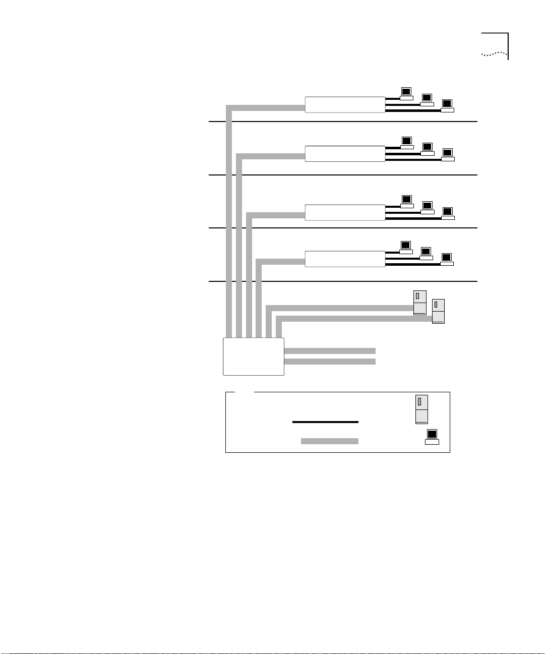
This section describes where to position the Switch 9100 within your
network. One common use of the Switch 9100 is on a Gigabit Ethernet
backbone. Figure 1
shows an example of a Gigabit Ethernet backbone
within a building.
Page 19
Network Configuration Example
Switch 3300
Switch 3300
Switch 3300
Switch 3300
19
Switch 9100
To Backbone
Key
Server
Workstation
91_001
Figure 1
Fast Ethernet
Gigabit Ethernet
Switch 9100 used in a backbone configuration
The Switch 3300 on each floor has a 1000Mbps full-duplex link to the
Switch 9100. Two servers on one floor of the building are connected to
the Switch 9100 by way of two Gigabit Ethernet links. The two Gigabit
Ethernet fiber ports on the Switch 9100 connect into a Gigabit Ethernet
campus backbone.
Using Gigabit Ethernet as a backbone technology removes bottlenecks by
providing scalable bandwidth, low-latency, and high-speed data
switching.
Page 20
20
C
HAPTER
1: S
WITCH
9100 O
VERVIEW
In addition to providing a Gigabit backbone between Fast Ethernet
workgroups, Gigabit Ethernet equipped file servers and services may be
directly attached to the Switch 9100 providing improved performance to
the Fast Ethernet desktop.
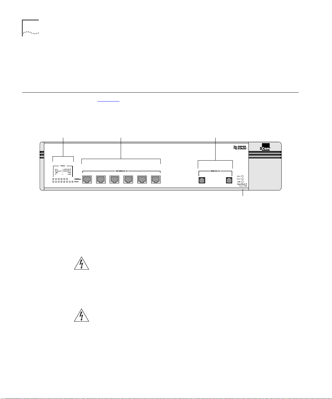
Switch 9100 Front View
Port status LEDs Gigabit Ethernet ports100/1000 Mbps ports
3C17705
Figure 2 shows the Switch 9100 front view.
Figure 2
456123
Switch 9100 front view
78
Unit status LEDs
The front panel has the following features:
Ports
WARNING: RJ-45 Ports.
These are shielded RJ-45 data sockets. They
cannot be used as telephone sockets. Only connect RJ-45 data
connectors to these sockets.
91_front
Either shielded or unshielded data cables with shielded or unshielded
jacks can be connected to these data sockets.
AVERTISSEMENT: Les ports RJ-45.
Il s'agit de prises femelles blindées
de données RJ-45. Vous ne pouvez pas les utiliser comme prise de
téléphone. Branchez uniquement des connecteurs de données RJ-45 sur
ces prises femelles.
Les câbles de données blindés ou non blindés, avec les jacks blindés ou
non blindés, l'un ou l'autre, peuvent être branchés à ces prises de courant
de données.
Page 21

21
WARNHINWEIS
Switch 9100 Front View
:
RJ-45 Ports. RJ-45-Anschlüsse.
Dies sind
abgeschirmte RJ-45-Datenbuchsen. Sie können nicht als
Telefonanschlußbuchsen verwendet werden. An diesen Buchsen dürfen
nur RJ-45-Datenstecker angeschlossen werden.
Diese Datenstecker können entweder mit abgeschirmten oder
unabgeschirmten Datenkabeln mit abgeschirmten oder unabgeschirmten
Klinkensteckern verbunden werden.
The Switch 9100 has six autosensing 100/1000BASE-TX ports using
standard RJ-45 connectors. It also has two 1000BASE-SX ports that use
standard MT-RJ connectors.
The Switch 9100 ports support the media types and distances listed in
Ta b l e 3
.
Table 3
Standard Media Type Mhz/Km Rating Maximum Distance
100BASE-TX Category 5 UTP Cable (100Mbps) 100 m
1000BASE-T Category 5 UTP Cable (1000Mbps) 100 m
1000BASE-SX (850 nm) 62.5/125 µm Multimode fiber
Media Types and Distances
62.5/125 µm Multimode fiber
50/125 µm Multimode fiber
50/125 µm Multimode fiber
160
200
400
500
220 m
275 m
500 m
550 m
For more information on 1000BASE-SX characteristics refer to IEEE Draft
P802.3z/D4.2 Tables 38-2 and 38-6.
LEDs
Ta b l e 4
Table 4
LED Color Indicates
1000BASE-SX Port Status LEDs
Link/activity Green
(continued) (continued)
Switch 9100 LEDs
describes the LED behavior on the Switch 9100.
Link is present; port is enabled.
Yellow
Green flashing
Off
Frames are being transmitted/received on this
port.
Link is present; port is disabled.
Link is not present.
Page 22
22
C
HAPTER
1: S
WITCH
9100 O
VERVIEW
Table 4
Switch 9100 LEDs (continued)
LED Color Indicates
100/1000BASE-TX Port Status LEDs
Link/activity Green
Yellow
Link is present; port is enabled.
Frames are being transmitted/received on this
port.
Green flashing
Off
Speed Status Green
Off
Link is present; port is disabled.
Link is not present.
1000BASE-T operation.
100BASE-TX operation.
Unit Status LED
Power 1 and Power 2 Green
Either or both LEDs green indicates the Switch
9100 is powered up.
Yellow
A yellow power LED indicates a power, overheat,
or fan failure on the corresponding PSU.
Off
Both LEDs off indicates the Switch 9100 is
powered off.
MGMT Green
Green flashing
(1Hz)
Green flashing
The Switch 9100 is operating normally.
Power On Self Test
download is in progress.
POST is in progress.
(0.5Hz)
Yellow
The Switch 9100 has failed POST.
(POST) complete, software
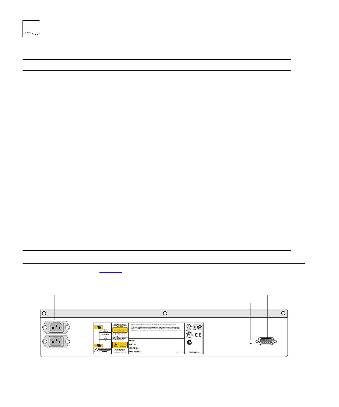
Switch 9100 Rear View
AC Connectors Console port
Figure 3 shows the Switch 9100 rear view.
Power 2
Power 1
Figure 3
Switch 9100 rear view
Reset
91_rear
Page 23

Factory Defaults
23
The rear panel has the following features:
Power Sockets
The Switch 9100 has two, fully redundant, load-sharing power supplies.
Both automatically adjust to the supply voltage. The power supplies
operate down to 90 V. The fuse is suitable for both 110 V AC and
220–240 V AC operation.
Serial Number
The serial number uniquely identifies this unit. You will need this serial
number for fault-reporting purposes.
MAC Address
This label shows the unique Ethernet MAC address assigned to this
device.
Console Port
The console port (9-pin, “D” type connector) is used to connect a
terminal and to carry out local out-of-band management.
Factory Defaults
Reset Button
The reset button reinitializes the switch. The unit reboots with the last
saved configuration settings.
Ta b l e 5 shows the factory defaults for the Switch 9100 features.
Table 5
Item Default Setting
Console port configuration 9600 baud, eight data bits, one stop bit, no
Serial or Telnet user account
Web network management Enabled
Virtual LANs One VLAN named
QoS All traffic is part of a single queue (qp2)
QoS monitoring Automatic roving
(continued)
Switch 9100 Factory Defaults
parity, XON/XOFF flow control enabled
admin
password
default VLAN; the default VLAN belongs to the
STPD named
with no password and
; all ports belong to the
default
s0
user
with no
Page 24

24
C
HAPTER
1: S
WITCH
9100 O
VERVIEW
Table 5
Switch 9100 Factory Defaults (continued)
Item Default Setting
Spanning Tree Protocol Disabled for the switch; enabled for each port in
the STPD
802.1p priority Recognition enabled
802.3x flow control Enabled on Gigabit Ethernet ports
802.1Q tagging All packets are untagged on the default VLAN
(
default)
Forwarding database aging
300 seconds (5 minutes)
period
IGMP Enabled
IGMP snooping Enabled
Port status Enabled on all ports
SNMP read community string
SNMP write community string
public
private
RMON history session Enabled
RMON alarms Enabled
Send trap if load is greater than 75% of available
bandwidth
Send trap if there are more than 10 errors in
1,000 packets
BOOTP Enabled on the default VLAN (
default
)
Page 25
2
I
NSTALLATION AND
This chapter describes the following:
How to decide where to install the Switch 9100
■
Ethernet configuration rules
■
How to install the switch in a rack or free-standing
■
How to connect equipment to the console port
■
How to check the installation using the
■
S
ETUP
Power On Self-Test (POST)
Determining the Switch 9100 Location
WARNING: Safety Information.
components from the Switch 9100 or carrying out any maintenance
procedures, you must read the safety information provided in Appendix A
of this guide.
AVERTISSEMENT: Consignes de sécurité.
tout composant du Switch 9100 ou d'entamer une procédure de
maintenance, lisez les informations relatives à la sécurité qui se trouvent
dans l'Appendice A de ce guide.
WARNHINWEIS: Sicherheitsinformationen.
aus dem Switch 9100 entfernen oder dem Switch 9100 hinzufuegen
oder Instandhaltungsarbeiten verrichten, lesen Sie die
Sicherheitsanweisungen, die in Appendix A (Anhang A) in diesem
Handbuch aufgefuehrt sind.
The Switch 9100 is suited for use in the office, where it can be
free-standing or mounted in a standard 19-inch equipment rack.
Alternatively, the device can be rack-mounted in a wiring closet or
equipment room. Two mounting brackets are supplied with the switch.
Before installing or removing any
Avant d'installer ou d'enlever
Bevor Sie Komponenten
Page 26

26
C
HAPTER
2: I
NSTALLATION AND SETUP
Configuration Rules
for Ethernet
CAUTION:
When using a rack mounting system, the switch must be
mounted on a shelf or runners. The rack mounting brackets alone are not
sufficient to support the weight of the switch. The rack mounting
brackets are provided to ensure stability across the horizontal plane. If
you stack switches, you must ensure that the shelf or runners are strong
enough to hold the combined weight. Ensure that the ventilation holes
are not obstructed.
After deciding where to install the switch, make sure that:
The switch is accessible and cables can be connected easily.
■
Water or moisture cannot enter the case of the unit.
■
Temperature must be within the range of 0 to 40 °C (32 to 104°F).
■
Air-flow around the unit and through the vents on the side of the case
■
is not restricted. You should provide a minimum of 75mm (3 in.)
clearance.
No objects are placed on top of the unit.
■
Units are not stacked more than four high if the switch is
■
free-standing.
The connectors, supported media types, and maximum distances for the
Switch 9100 are described in Chapter 1
.
Installing the Switch 9100
Rack Mounting
The Switch 9100 can be mounted in a rack, or placed free-standing on a
tabletop.
The Switch 9100 is 2U high and will fit in most standard 19-inch racks.
CAUTION:
The switch should only be used in a rack if it is mounted on
runners, a shelf, or a tray to support the weight. The rack mount kits
alone are not sufficient to support the weight of the switch. The rack
mount kits must not be used to suspend the switch from under a table or
desk, or attach it to a wall.
CAUTION:
Disconnect all cables from the switch before continuing.
Remove all self-adhesive pads from the underside of the switch, if they
have been fitted.
Page 27
Installing the Switch 9100
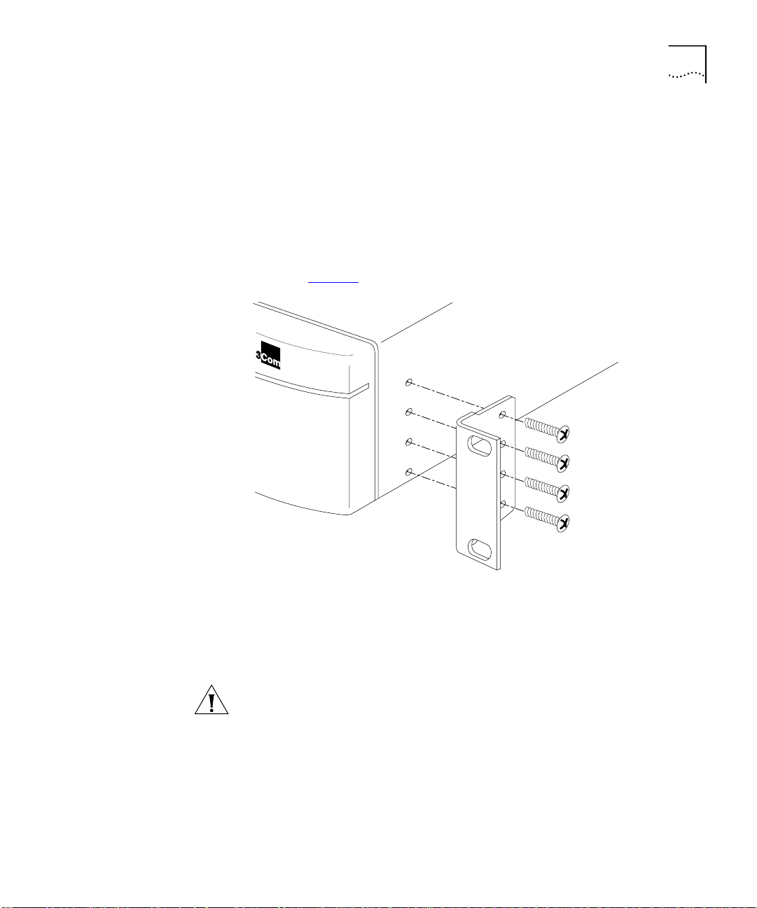
To install the mounting brackets on the switch, follow these steps:
Place the switch the right way up on a hard flat surface, with the front
1
facing toward you.
Remove the existing screws from the sides of the chassis.
2
Locate a mounting bracket over the mounting holes on one side of the
3
unit.
Insert the four screws and fully tighten with a suitable screwdriver, as
4
shown in Figure 4
.
27
Free-Standing
Figure 4
Repeat the three previous steps for the other side of the switch.
5
Refer to the instructions that shipped with your rack, runners, shelf or
6
Fitting the mounting bracket
tray to complete the installation of the switch into the mounting rack.
CAUTION:
When using rack mounting runners, a shelf, or a tray, make
sure that the ventilation holes on the side of the switch are not
obstructed.
Connect cables.
7
The Switch 9100 is supplied with four self-adhesive rubber pads. Apply
the pads to the underside of the device by sticking a pad in the marked
area at each corner of the switch.
Page 28

28
C
HAPTER
2: I
NSTALLATION AND SETUP
Stacking the Switch
and Other Devices
Connecting Equipment to the Console Port
Up to four units can be placed on top of one another. If mixing
SuperStack II devices, the smaller units must be positioned at the top
using rubber pads.
This section relates only to physically placing the devices on top of each
other. The switch cannot be used to form a logical stack. It cannot be
linked to other switches using special expansion cables to form a larger
switch.
Apply the pads to the underside of the device by sticking a pad in the
marked area at each corner of the switch. Place the devices on top of
each other, ensuring that the pads of the upper device line up with the
recesses of the lower device.
Connection to the console port is used for direct local management. The
Switch 9100 console port settings are set as follows:
■
Baud rate
■
Data bits
■
Stop bit
■
Parity
■
Flow control
— 9600
— 8
— 1
— None
— XON/XOFF
The terminal connected to the console port on the switch must be
configured with the same settings. This procedure will be described in the
documentation supplied with the terminal.
Appropriate cables are available from your local supplier. To make your
own cables, pinouts for a DB-9 male console connector are described in
Ta b l e 6
Table 6
Function Pin Number Direction
DCD (data carrier detect) 1 In
RXD (receive data) 2 In
TXD (transmit data) 3 Out
DTR (data terminal ready) 4 Out
(continued) (continued)
.
Console Connector Pinouts
Page 29
Connecting Equipment to the Console Port
29
Table 6
Function Pin Number Direction
GND (ground) 5 -
DSR (data set ready) 6 In
RTS (request to send) 7 Out
CTS (clear to send 8 In
Console Connector Pinouts (continued)
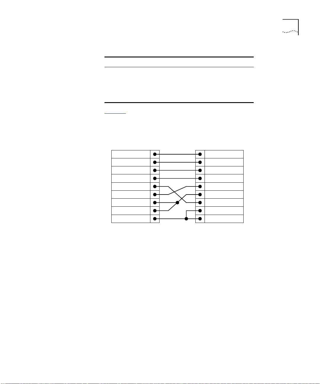
Figure 5 shows the pin-outs for a 9-pin to RS-232 25-pin null modem
cable.
Switch 9100
Cable connector: 9-pin female
Screen
TxD
RxD
Ground
RTS
CTS
DSR
DCD
DTR
Shell
3
2
5
7
8
6
1
4
PC/Terminal
Cable connector: 25-pin male/female
1
Screen
3
2
7
4
20
5
6
8
RxD
TxD
Ground
RTS
DTR
CTS
DSR
DCD
91_ser1
Figure 5
Null modem cable pin-outs
Page 30
30
C
HAPTER
2: I
NSTALLATION AND SETUP
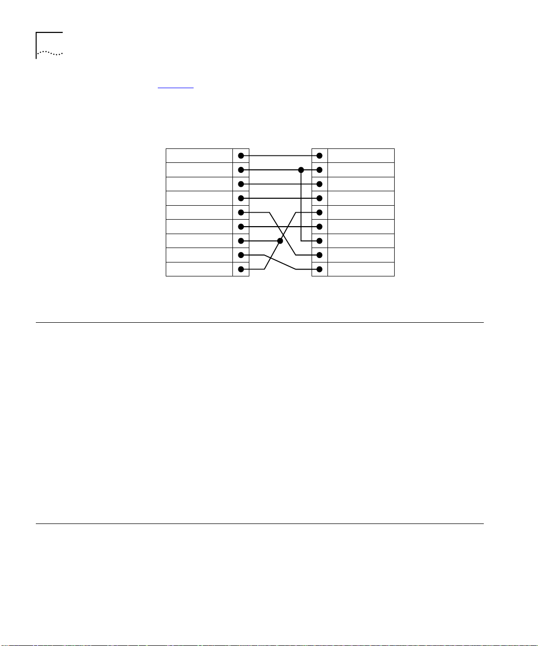
Figure 6 shows the pin-outs for a 9-pin to 9-pin PC-AT serial null modem
cable.
Powering-up the Switch
Switch 9100
Cable connector: 9-pin female
Screen
DTR
TxD
RxD
CTS
Ground
DSR
RTS
DCD
Figure 6
Shell
4
3
2
8
5
6
7
1
PC-AT serial cable pin-outs
PC-AT Serial Port
Cable connector: 9-pin female
Shell
Screen
1
2
3
4
5
6
7
8
DCD
RxD
TxD
DTR
Ground
DSR
RTS
CTS
91_ser2
The Switch 9100 contains two power supplies. When both are
connected, the power supplies operate in a load-sharing configuration. If
one power supply fails, the other power supply takes over, ensuring
uninterrupted network operation. Either one, or both power supplies may
be connected to power the switch. It is recommended that you connect
both power supplies.
Checking the Installation
Power On Self-Test
(POST)
To power-up the switch, follow these steps:
Connect one or both power cables to the switch.
1
Connect the power cable(s) to the wall outlet(s).
2
The switch automatically powers-up once it has been connected to the
wall outlet.
After turning on power to the Switch 9100, the device performs a
On Self-Test
(POST).
During the POST, all ports are temporarily disabled, the packet LED is off,
the power LED is on, and the MGMT LED flashes green. The MGMT LED
flashes until the switch has successfully passed the POST.
Power
Page 31

Logging on for the First Time
31
If the switch passes the POST, the MGMT LED stops blinking and remains
green. If the switch fails the POST, the MGMT LED shows a solid yellow
light.
Logging on for the
First Time
After the switch has completed the POST, it is operational. Once
operational, you can log on to the switch and configure an IP address for
the default VLAN (named
default
).
To manually configure the IP settings, perform the following steps:
Connect a terminal or workstation running terminal emulation software
1
to the console port.
At your terminal, press [Return] until you see the logon prompt.
2
At the logon prompt, enter the default user name
3
admin
to log on with
administrator privileges. For example:
login: admin
Administrator capabilities allow you to access all switch functions. For
more information on switch security, refer to Chapter 3
At the password prompt, press [Return].
4
The default name,
admin,
has no password assigned. When you have
.
successfully logged on to the switch, the command-line prompt displays
the name of the switch in its prompt.
Assign an IP address and subnetwork mask for VLAN
5
default.
The
example below assigns an IP address of 123.45.67.8 and a subnetwork
mask of 255.255.255.0.
config vlan default ipaddress 123.45.67.8 255.255.255.0
Your changes take effect immediately.
Save your configuration changes so that they will be in effect after the
6
next switch reboot, by typing
save
For more information on saving configuration changes, refer to
Chapter 10
When you are finished using the facility, log out of the switch by typing
7
logout
.
Page 32

32
C
HAPTER
2: I
NSTALLATION AND SETUP
Page 33

3
A
CCESSING THE
This chapter provides the following required information to begin
managing the Switch 9100:
Understanding the command syntax
■
Line-editing commands
■
Command history substitution
■
Configuring the switch for management
■
Switch management methods
■
Configuring SNMP
■
Checking basic connectivity
■
Enabling and disabling individual ports
■
Configuring the port speed (100/1000BASE-TX ports only)
■
S
WITCH
Configuring half- or full-duplex mode
■
Creating load-sharing groups on multiple ports
■
For configuration changes to be retained through a power cycle or
reboot, you must issue a SAVE command after you have made the
change. For more information on the SAVE command, refer to
Chapter 10
.
Page 34

34
C
HAPTER
3: A
CCESSING THE SWITCH
Understanding the Command Syntax
This section describes the steps to take when entering a command. Refer
to the sections that follow for detailed information on using the
command-line interface.
To use the command-line interface (CLI), follow these steps:
When entering a command at the prompt, ensure that you have the
1
appropriate privilege level.
Most configuration commands require you to have the administrator
privilege level.
Enter the command name.
2
If the command does not include a parameter or values, skip to Step 3. If
the command requires more information, continue to Step 2a.
If the command includes a parameter, enter the parameter name and
a
values.
The value part of the command specifies how you want the parameter
b
to be set. Values include numerics, strings, or addresses, depending on
the parameter.
After entering the complete command, press [Return].
3
If an asterisk (*) appears in front of the command-line prompt, it
indicates that you have outstanding configuration changes that have not
been saved. For more information on saving configuration changes, refer
to Chapter 10
.
Syntax Helper
Command
Completion with
Syntax Helper
The CLI has a built-in syntax helper. If you are unsure of the complete
syntax for a particular command, enter as much of the command as
possible and press [Return]. The syntax helper provides a list of options
for the remainder of the command.
The syntax helper also provides assistance if you have entered an incorrect
command.
The switch provides command completion by way of the [Tab] key. If you
enter a partial command, pressing the [Tab] key posts a list of available
options, and places the cursor at the end of the command.
Page 35

Understanding the Command Syntax
35
Abbreviated Syntax
Command Shortcuts
Abbreviated syntax is the shortest, most unambiguous, allowable
abbreviation of a command or parameter. Typically, this is the first three
letters of the command.
When using abbreviated syntax, you must enter enough characters to
make the command unambiguous, and distinguishable to the switch.
All named components of the switch configuration must have a unique
name. Components are named using the
create
command. When you
enter a command to configure a named component, you do not need to
use the keyword of the component. For example, to create a VLAN, you
must enter a unique VLAN name:
create vlan engineering
Once you have created the VLAN with a unique name, you can then
eliminate the keyword
from all other commands that require the
vlan
name to be entered. For example, instead of entering the Switch 9100
command
config vlan engineering delete port 1-3,6
you could enter the following shortcut:
config engineering delete port 1-3,6
Switch 9100
Numerical Ranges
Names
Commands that require you to enter one or more port numbers on a
Switch 9100 use the parameter
<portlist>
in the syntax. A portlist can
be a range of numbers, for example:
ports 1- 3
You can add additional port numbers to the list, separated by a comma:
ports 1- 3,6 ,8
All named components of the switch configuration must have a unique
name. Names must begin with an alphabetical character and are
delimited by whitespace, unless enclosed in quotation marks.
Page 36

36
C
HAPTER
3: A
CCESSING THE SWITCH
Symbols
You may see a variety of symbols shown as part of the command syntax.
These symbols explain how to enter the command, and you do not type
them as part of the command itself. Ta b l e 7
summarizes command syntax
symbols.
Table 7
Symbol Description
angle brackets < > Enclose a variable or value. You must specify the variable or value. For
square brackets [ ] Enclose a required value or list of required arguments. One or more values or
vertical bar | Separates mutually exclusive items in a list, one of which must be entered. For
braces { } Enclose an optional value or a list of optional arguments. One or more values
Command Syntax Symbols
example, in the syntax
config vlan <name> ipaddress <ip_address>
you must supply a VLAN name for
<ip_address>
brackets.
arguments can be specified. For example, in the syntax
use image [primary | secondary]
you must specify either the primary or secondary image when entering the
command. Do not type the square brackets.
example, in the syntax
config snmp community [readonly | readwrite] <string>
you must specify either the read or write community string in the command.
Do not type the vertical bar.
or arguments can be specified. For example, in the syntax
reboot {<date> <time> | cancel}
you can specify either a particular date and time combination, or the keyword
cancel
argument, the command will prompt, asking if you want to reboot the switch
now. Do not type the braces.
to cancel a previously scheduled reboot. If you do not specify an
when entering the command. Do not type the angle
<name>
and an address for
Page 37

Line-Editing Keys
37
Line-Editing Keys
Table 8
Key(s) Description
Backspace Deletes character to the left of cursor and shifts the remainder of line to left.
Delete or [Ctrl] + D Deletes character under cursor and shifts the remainder of line to left.
[Ctrl] + K Deletes characters from under cursor to the end of the line.
Insert Toggles on and off. When toggled on, inserts text and shifts previous
Left Arrow Moves cursor to left.
Right Arrow Moves cursor to right.
[Ctrl] + L Clears the screen and moves the cursor to the beginning of the line.
[Ctrl] + U Clears all characters typed from the cursor to the beginning of the line.
[Ctrl] + W Deletes the previous word.
Up Arrow Displays the previous command in the command history buffer and places
Down Arrow Displays the next command in the command history buffer and places cursor
Line-Editing Keys
Command History
Ta b le 8 describes the line-editing keys available using the CLI.
text to right.
cursor at end of command.
at end of command.
The switch “remembers” the last 49 commands you have entered. You
can display a list of these commands by using the following command:
history
Common Commands
Ta b l e 9 describes common commands used to manage the switch.
Commands specific to a particular feature are described in the other
chapters of this guide.
Table 9
Command Description
creat e acc ou nt [admin | user]
<username> {encrypted} {<password>}
(continued)
Common Commands
Creates a user account. The
option should only be used by the switch to
generate an ASCII configuration (using the
uploa d co nfi gu ration
parsing a switch-generated configuration
(using the
command).
encrypted
command), and
download configuration
Page 38

38
C
HAPTER
3: A
CCESSING THE SWITCH
Table 9
Common Commands (continued)
Command Description
creat e vla n <n am e>
config account <username> {encrypted}
{<password>}
Creates a VLAN.
Configures a user account password.
Passwords must have a minimum of four
characters and can have a maximum of 12
characters. User names and passwords are
case-sensitive.
config banner
Configures the banner string. You can enter
up to 24 rows of 80-column text that is
displayed before the login prompt of each
session. Press [Return] at the beginning of a
line to terminate the command and apply the
banner. To clear the banner, press [Return] at
the beginning of the first line.
config time <date> <time>
Configures the system date and time. The
format is as follows:
mm/dd/yyyy hh:mm:ss
The time uses a 24-hour clock format. You
cannot set the year past 2023.
config timezone <gmt_offset> {autodst |
noauto dst}
Configures the time zone information to the
configured offset from GMT time. The format
of
gmt_offset
time. Specify:
autodst
■
Savings Time change.
nosautodst
■
Daylight Savings Time change.
The default setting is
config vlan <name> ipaddress
<ip_address> {<mask>}
disable autodst
Configures an IP address and subnet mask
for a VLAN.
Disables automatic Daylight Savings Time
change.
enable autodst
Enables automatic Daylight Savings Time
change.
enable bootp vlan [<name> | all]
enabl e cli -c on fig-logg ing
Enables BOOTP for one or more VLANs.
Enables logging CLI configuration commands
to the syslog for auditing purposes.
enabl e cli pa gi ng
Enables pausing at the end of each CLI
screen, allowing you to use a scripting
language to get switch status.
(continued)
is +/- minutes from GMT
— Enables automatic Daylight
— Disables automatic
autodst
.
Page 39

Common Commands
39
Table 9
Command Description
enabl e idl et im eout
enable telnet {access-profile
<access_profile> | none} {port
<tcp_port_number>}
enable web {access-profile
<access_profile> | none} {port
<tcp_port_number>}
history
clear session <number>
disable bootp vlan [<name> | all]
disable cli-config-logging
disable clipaging
disable idletimeout
disable telnet
disable web
delete account <username>
delet e vla n <n am e>
(continued)
Common Commands (continued)
Enables a timer that disconnects all sessions
(both Telnet and console) after 20 minutes of
inactivity. The default setting is disabled.
Enables Telnet access to the switch. By
default, Telnet is enabled with no access
profile, and uses TCP port 23. The
option removes any previously configured
access profile assignment.
Enables web access to the switch. By default,
web access is enabled with no access profile,
using TCP port number 80. You must reboot
the switch before this command takes effect.
The
none
configured access profile assignment.
Displays the previous 49 commands entered
on the switch.
Terminates a Telnet session from the switch.
Disables BOOTP for one or more VLANs.
Disables logging CLI configuration
commands to the syslog for auditing
purposes.
Disables pausing at the end of each CLI
screen.
Disables the timer that disconnects all
sessions. Once disabled, console sessions
remain open until the switch is rebooted or
you logoff. Telnet sessions remain open until
you close the Telnet client.
Disables Telnet access to the switch.
Disables Web access to the switch.
Deletes a user account.
Deletes a VLAN.
none
option removes any previously
Page 40

40
C
HAPTER
3: A
CCESSING THE SWITCH
Table 9
Command Description
unconfig switch {all}
show banner
Configuring Management Access
Common Commands (continued)
The Switch 9100 supports the following two level levels of management:
User
■
Administrator
■
Resets all switch parameters (with the
exception of defined user accounts, and date
and time information) to the factory defaults.
If you specify the keyword
account information is reset as well.
Displays the user-configured banner.
A user-level account has viewing access to all manageable parameters,
with the exception of the following:
User account database
■
SNMP community strings
■
A user-level account can use the
reachability, and change the password assigned to the account name. If
you have logged on with user capabilities, the command-line prompt
ends with a (>) sign. For example:
, the user
all
command to test device
ping
3C17705:2>
An administrator-level account can view and change all switch
parameters. It can also add and delete users, and change the password
associated with any account name. The administrator can disconnect a
management session that has been established by way of a Telnet
connection. If this happens, the user logged on by way of the Telnet
connection is notified that the session has been terminated.
If you have logged on with administrator capabilities, the command-line
prompt ends with a (#) sign. For example:
3C17705:18#
The prompt text is taken from the SNMP
sysname
setting. The number
that follows the colon indicates the sequential line/command number.
Page 41

Configuring Management Access
41
If an asterisk (*) appears in front of the command-line prompt, it indicates
that you have outstanding configuration changes that have not been
saved. For example:
*3C177 05:19#
For more information on saving configuration changes, refer to
Chapter 10
.
Default Accounts
By default, the switch is configured with two accounts, as shown in
Ta b l e 1 0
Table 10
Account Name Access Level
admin This user can access and change all manageable
user This user can view (but not change) all manageable
.
Default Accounts
parameters. The admin account cannot be deleted.
parameters, with the following exceptions:
This user cannot view the user account database.
■
This user cannot view the SNMP community strings.
■
Changing the Default Password
Default accounts do not have passwords assigned to them. Passwords
must have a minimum of four characters and can have a maximum of 12
characters.
User names and passwords are case-sensitive.
To add a password to the default admin account, follow these steps:
Log in to the switch using the name
1
At the password prompt, press [Return].
2
admin
.
Add a default admin password by typing the following:
3
config account admin
Enter the new password at the prompt.
4
Re-enter the new password at the prompt.
5
Page 42

42
C
HAPTER
3: A
CCESSING THE SWITCH
To add a password to the default user account, follow these steps:
Creating a
Management
Account
Log in to the switch using the name
1
At the password prompt, press [Return], or enter the password that you
2
have configured for the
Add a default user password by typing the following:
3
config account user
Enter the new password at the prompt.
4
Re-enter the new password at the prompt.
5
admin
account.
admin
.
If you forget your password while logged out of the command-line
interface, contact your supplier, who will advise on your next course of
action.
The switch can have a total of 16 management accounts. You can use the
default names (
admin
and
), or you can create new names and
user
passwords for the accounts. Passwords must have a minimum of four
characters and can have a maximum of 12 characters.
To create a new account, follow these steps:
Log in to the switch as
1
At the password prompt, press [Return], or enter the password that you
2
have configured for the
admin
admin
.
account.
Add a new user by using the following command:
3
create account [admin | user] <username> {encrypted}
Enter the password at the prompt.
4
Re-enter the password at the prompt.
5
Viewing Accounts
To view the accounts that have been created, you must have
administrator privileges. Use the following command to see the accounts:
show accounts
Page 43

Methods of Managing the Switch 9100
Deleting an Account
To delete an account, you must have administrator privileges. Use the
following command to delete an account:
delete account <username>
43
Methods of
Managing the
Switch 9100
Using the Console
Interface
The account name
admin
cannot be deleted.
You can manage the switch using the following methods:
Access the CLI by connecting a terminal (or workstation with
■
terminal-emulation software) to the console port.
Access the CLI over a TCP/IP network using a Telnet connection.
■
Access the Web interface over a TCP/IP network, using a standard
■
Web browser (such as Netscape Navigator 3.0 or greater, or Microsoft
Internet Explorer 3.0 or greater).
Use an SNMP Network Manager over a network running the IP
■
protocol.
The switch can support multiple user sessions concurrently, as follows:
One console session
■
Eight Telnet sessions
■
One Web session
■
The CLI built into the switch is accessible by way of the 9-pin, RS-232 port
labelled
console
, located on the back of the Switch 9100.
Using Access
Profiles
For more information on the console port pinouts, refer to Chapter 2.
Once the connection is established, you will see the switch prompt and
you may log in.
Access profiles are used by several switch features as a way to restrict
access. An access profile is a named list of IP addresses and subnet masks.
To use access profiles, you must first define the list, and then apply the
named list to the desired application.
Page 44

44
C
HAPTER
3: A
CCESSING THE SWITCH
The most common applications that use access profiles allow you to
remotely manage the switch across the network, for example:
SNMP read access
■
SNMP read and write access
■
Te l n e t
■
Web access
■
Creating an Access
Profile
Access profiles are created to specifically permit or deny users access to
an application. Access is restricted by assigning an access profile to the
service that is being used for remote access. First, create and configure
the access profile with the desired controls. Next, configure the
application to use the access profile that you have created. You must
configure the application to use the named access profile. Otherwise, no
restrictions are applied. Ta b l e 1 1
Table 11
Command Description
config access-profile <access_profile>
add ipaddress <ipaddress>
<subnet_mask>}
config access-profile <access_profile>
delete ipaddress <ipaddress>
<subnet_mask>
config access-profile <access_profile>
mode [permit | deny]
create access-profile <access_profile>
type ip add re ss
delet e acc es s- profile <a ccess_pro fi le>
show ac ces s- pr ofile <acc ess_profi le >
Access Profile Configuration Commands
Adds an IP address to the access profile.
Deletes an IP address from the access profile.
Configures the access profile to be one of the
following:
permit
■
match the access profile description.
deny
■
the access profile description.
The default setting is
Creates an access profile. Once the access
profile is created, one or more addresses can
be added to it, and the profile can be used to
control access to an application.
Deletes an access profile.
Displays access-profile related information for
the switch.
lists access profile commands.
— Allows the addresses that
— Denies the addresses that match
permit
.
Page 45

Using Access Profiles
45
The subnet mask specified in the access profile command is interpreted as
a
reverse mask
. A reverse mask indicates the bits that are significant in
the IP address. In other words, a reverse mask specifies the part of the
address that must match the IP address to which the profile is applied.
If you configure an IP address that is an exact match that is specifically
denied or permitted, use a mask of /32 (for example, 141.251.24.28/32).
If the IP address represents a subnet address that you wish to deny or
permit, then configure the mask to cover only the subnet portion (for
example, 141.251.10.0/24).
If you are using off-byte boundary subnet masking, the same logic
applies, but the configuration is more tricky. For example, the address
141.251.24.128/27 represents any host from subnet 141.251.24.128.
Access Profile Rules
The following rules apply when using access profiles:
Only one access profile can be applied to each application.
■
The access profile can either permit or deny the entries in the profile.
■
The same access profile can be applied to more than one application.
■
There is an implicit aspect to access profiles. For instance, if an access
profile of mode permit is applied, then all other sources are assumed
denied, and are not permitted access to the application. On the other, if
an access profile of mode deny is applied, then all other sources are
assumed permitted.
Access Profile Example
The following example creates an access profile named
testpro
, and
denies access for the device with the IP address 192.168.10.10:
create access-profile testpro type ipaddress
config access-profile testpro mode deny
config access-profile testpro add ipaddress 192.168.10.10/32
The following command applies the access profile
enable telnet access-profile testpro
testpro
to Telnet:
To view the contents of an access profile, type:
show access-profile <access_profile>
Page 46

46
C
HAPTER
3: A
CCESSING THE SWITCH
To view the Telnet configuration, type:
show management
Using Telnet
Connecting to
Another Host Using
Te l n e t
Any workstation with a Telnet facility should be able to communicate
with the switch over a TCP/IP network.
Up to eight active Telnet sessions can access the switch concurrently. If
idle timeouts
are enabled, the Telnet connection will time out after
20 minutes of inactivity. If a connection to a Telnet session is lost
inadvertently, the switch terminates the session within two hours.
Before you can start a Telnet session, you must set up the IP parameters
described in the section “
Configuring Switch IP Parameters,” later in this
chapter. Telnet is enabled by default.
To open the Telnet session, you must specify the IP address of the device
that you want to manage. Check the user manual supplied with the
Telnet facility if you are unsure of how to do this.
Once the connection is established, you will see the switch prompt and
you may log in.
You can Telnet from the current CLI session to another host using the
following command:
telnet <ipaddress> {<port_number>}
If the TCP port number is not specified, the Telnet session defaults to
port 23. Only VT100 emulation is supported.
Configuring Switch IP
Parameters
To manage the switch by way of a Telnet connection or by using an SNMP
Network Manager, you must first configure the switch IP parameters.
Using a BOOTP Server
If you are using IP and you have a Bootstrap Protocol (BOOTP) server set
up correctly on your network, you must add the following information to
the BOOTP server:
Switch Media Access Control (MAC) address
■
IP address
■
Page 47

47
Subnet address mask (optional)
■
Using Telnet
The switch MAC address is found on the rear label of the switch.
Once this is done, the IP address and subnetwork mask for the switch will
be downloaded automatically. You can then start managing the switch
without further configuration.
You can enable BOOTP on a per-VLAN basis by using the following
command:
enable bootp vlan [<name> | all]
By default, BOOTP is enabled on the
default
VLAN.
If you configure the switch to use BOOTP, the switch IP address is not
retained through a power cycle, even if the configuration has been saved.
To retain the IP address through a power cycle, you must configure the IP
address of the VLAN using the command-line interface, Telnet, or Web
interface.
All VLANs within a switch that are configured to use BOOTP to get their IP
address use the same MAC address. Therefore, if you are using BOOTP
relay through a router, the BOOTP server must be capable of
differentiating its relay based on the gateway portion of the BOOTP
packet.
Manually Configuring the IP Settings
If you are using IP without a BOOTP server, you must enter the IP
parameters for the switch in order for the SNMP Network Manager,
Telnet software, or Web interface to communicate with the device. To
assign IP parameters to the switch, you must do the following:
Log in to the switch with administrator privileges.
■
Assign an IP address and subnetwork mask to a VLAN.
■
The switch comes configured with a default VLAN named
default
. To
use Telnet or an SNMP Network Manager, you must have at least one
VLAN on the switch, and it must be assigned an IP address and
subnetwork mask. IP addresses are always assigned to a VLAN. The
switch can be assigned multiple IP addresses.
For information on creating and configuring VLANs, refer to Chapter 4
.
Page 48

48
C
HAPTER
3: A
CCESSING THE SWITCH
1
2
3
4
To manually configure the IP settings, perform the following steps:
Connect a terminal or workstation running terminal-emulation software
to the console port.
At your terminal, press [Return] one or more times until you see the login
prompt.
At the login prompt, enter your user name and password. Note that they
are both case-sensitive. Ensure that you have entered a user name and
password with administrator privileges.
If you are logging in for the first time, use the default user name
■
admin
login: admin
to log in with administrator privileges. For example:
Administrator capabilities enable you to access all switch functions.
The default user names have no passwords assigned.
If you have been assigned a user name and password with
■
administrator privileges, enter them at the login prompt.
At the password prompt, enter the password and press [Return].
When you have successfully logged in to the switch, the command-line
prompt displays the name of the switch in its prompt.
Assign an IP address and subnetwork mask for the default VLAN by using
5
the following command:
config vlan <name> ipaddress <ipaddress> {<subnet_mask>}
For example:
config vlan default ipaddress 123.45.67.8 255.255.255.0
Your changes take effect immediately.
As a general rule, when configuring any IP addresses for the switch, you
can express a subnet mask by using dotted decimal notation, or by using
classless inter-domain routing notation (CIDR). CIDR uses a forward slash
plus the number of bits in the subnet mask. Using CIDR notation, the
command identical to the one above would be:
config vlan default ipaddress 123.45.67.8 / 24
Configure the default route for the switch using the following command:
6
config iproute add default <ipaddress> {<metric>}
Page 49

Using Telnet
For example:
config iproute add default 123.45.67.1
Save your configuration changes so that they will be in effect after the
7
next switch reboot, by typing
save
For more information on saving configuration changes, refer to
Chapter 10
When you are finished using the facility, log out of the switch by typing
8
.
49
Disconnecting a
Telnet Session
Disabling Telnet
Access
logout
or
quit
An administrator-level account can disconnect a management session
that has been established by way of a Telnet connection. If this happens,
the user logged in by way of the Telnet connection is notified that the
session has been terminated.
To terminate a Telnet session, follow these steps:
Log in to the switch with administrator privileges.
1
Determine the session number of the session you want to terminate by
2
using the following command:
show session
Terminate the session by using the following command:
3
clear session <session_number>
By default, Telnet services are enabled on the switch. You can choose to
disable Telnet by entering:
disabl e tel ne t
To re-enable Telnet on the switch, at the console port enter
enable telnet {access-profile <access_profile> | none} {port
<port_number>}
You must be logged in as an administrator to enable or disable Telnet.
Page 50

50
C
HAPTER
3: A
CCESSING THE SWITCH
IP Host
Configuration
Ta b l e 1 2 describes the commands that are used to configure IP settings
on the switch.
Commands
Table 12
Command Description
config iparp add <ipaddress>
<mac_address>
config iparp delete <ipaddress>
config iparp timeout <minutes>
clear iparp {<ipaddress> | vlan <name>}
config iproute add default <gateway>
{<metric>}
config iproute delete default <gateway>
show iparp {<ipaddress> | vlan <name> |
perman ent }
show iproute {vlan <name> | <ipaddress>
<mask> }
IP Host Configuration Commands
Adds a permanent entry to the Address
Resolution Protocol (ARP) table. Specify the IP
address and MAC address of the entry.
Deletes an entry from the ARP table. Specify
the IP address of the entry.
Configures the IP ARP timeout period. The
default setting is 20 minutes. A setting of 0
disables ARP aging.
Removes dynamic entries in the IP ARP table.
Permanent IP ARP entries are not affected.
Adds a default gateway to the routing table.
A default gateway must be located on a
configured IP interface. If no metric is
specified, the default metric of one is used.
Deletes a default gateway from the routing
table.
Displays the IP ARP table. You can filter the
display by IP address, VLAN, or permanent
entries.
Displays the contents of the IP routing table.
Using the Web Interface
The Web Interface is device-management software running in the switch
that enables you to access the switch over a TCP/IP network using a
standard Web browser. Any properly configured standard Web browser
that supports frames (such as Netscape Navigator 3.0 or Microsoft
Internet Explorer 3.0) can manage the switch over a TCP/IP network.
For more information on assigning an IP address, refer to the section,
“
Configuring Switch IP Parameters,” on page 46.
Page 51

Using SNMP
51
The default home page of the switch can be accessed using the following
command:
http://<ipaddress>
When you access the home page of the switch, you are presented with
the Logon screen.
Disabling Web Access
Using SNMP
For more information on using the Web Interface, refer to Chapter 9
.
By default, Web access is enabled on the switch. To disable it, enter the
following command:
disabl e web
To re-enable Web access, enter the following command:
enable web {access-profile <access_profile> | none} {port
<tcp_port_number>}
Reboot the switch for these changes to take effect.
For more information on rebooting the switch, refer to Chapter 10
.
Any Network Manager running the Simple Network Management
Protocol (SNMP) can manage the switch, provided the Management
Information Base (MIB) is installed correctly on the management station.
Each Network Manager provides its own user interface to the
management facilities.
The following sections describe how to get started if you want to use an
SNMP manager. It assumes you are already familiar with SNMP
management.
Accessing Switch
Agents
Supported MIBs
To have access to the SNMP agent residing in the switch, at least one
VLAN must have an IP address assigned to it.
For more information on assigning IP addresses, refer to Ta bl e 9
.
Any Network Manager running SNMP can manage the switch, provided
the MIB is installed correctly on the management station. In addition to
private MIBs, the switch supports the standard MIBs listed in Appendix B
.
Page 52

52
C
HAPTER
3: A
CCESSING THE SWITCH
Configuring SNMP
Settings
The following SNMP parameters can be configured on the switch:
■
Authorized trap receivers
— An authorized trap receiver can be one
or more network management stations on your network. The switch
sends SNMP traps to all trap receivers. You can have a maximum of six
trap receivers configured for each switch. Entries in this list can be
created, modified, and deleted using the RMON2 trapDestTable MIB
variable, as described in RFC 2021.
■
Authorized managers
— An authorized manager can be either a
single network management station, or a range of addresses (for
example, a complete subnet) specified by a prefix and a mask. The
switch can have a maximum of eight authorized managers.
■
Community strings
— The community strings allow a simple method
of authentication between the switch and the remote Network
Manager. There are two types of community strings on the switch.
Read community strings provide read-only access to the switch. The
default read-only community string is
. Read-write community
public
strings provide read and write access to the switch. The default
read-write community string is
. A total of eight community
private
strings can be configured on the switch. The community string for all
authorized trap receivers must be configured on the switch for the
trap receiver to receive switch-generated traps. SNMP community
strings can contain up to 126 characters.
■
System contact
(optional) — The system contact is a text field that
enables you to enter the name of the person(s) responsible for
managing the switch.
■
System name
— The system name is the name that you have
assigned to this switch. The default name is the model name of the
switch (for example, 3C17705).
■
System location
(optional) — Using the system location field, you
can enter an optional location for this switch.
Ta b l e 1 3
Table 13
Command Description
enabl e snm p ac ce ss
enabl e snm p tr ap s
(continued)
SNMP Configuration Commands
describes SNMP configuration commands.
Turns on SNMP support for the switch.
Turns on SNMP trap support.
Page 53

Using SNMP
53
Table 13
Command Description
config snmp access-profile [readonly |
readwrite] {<access_profile> | none}
confi g snm p ad d tr apreceive r
<ipad dr ess > co mmunity <s tring>
config snmp community [readonly |
readwrite] <string>
config snmp delete trapreceiver
[<ip_address> community <string> | all]
config snmp syscontact <string>
confi g snm p sy sn ame <string >
confi g snm p sy sl ocation <st ring>
SNMP Configuration Commands (continued)
Applies an access profile for SNMP access.
You can create different access profiles for
readonly and readwrite access to the switch.
The
none
configured access profile assignment.
Adds the IP address of a specified trap
receiver. The IP address can be a unicast,
multicast, or broadcast. A maximum of six
trap receivers is allowed.
Adds an SNMP read or read/write community
string. The default
string is
community string is
community string can have a maximum of
126 characters, and can be enclosed by
double quotation marks.
Deletes the IP address of a specified trap
receiver or all authorized trap receivers.
Configures the name of the system contact.
A maximum of 255 characters is allowed.
Configures the name of the switch. A
maximum of 32 characters is allowed. The
default sysname is the model name of the
device (for example,
sysname
Configures the location of the switch. A
maximum of 255 characters is allowed.
public
option removes any previously
readonly
. The default
private
3C17705)
appears in the switch prompt.
community
readwrite
. Each
. The
Displaying SNMP
Settings
To display the SNMP settings configured on the switch, enter the
following command:
show management
This command displays the following information:
Enable/disable state for Telnet, SNMP, and Web access
■
SNMP community strings
■
Authorized SNMP station list
■
SNMP trap receiver list
■
RMON polling configuration
■
Page 54

54
C
HAPTER
3: A
CCESSING THE SWITCH
Login statistics
■
Access profile assignments
■
Resetting and
To reset and disable SNMP settings, use the commands in Ta b l e 1 4
Disabling SNMP
Table 14
Command Description
disable snmp access
disable snmp traps
unconfig management
Checking Basic Connectivity
SNMP Reset and Disable Commands
Disables SNMP on the switch. Disabling SNMP access does
not affect the SNMP configuration (for example,
community strings).
Prevents SNMP traps from being sent from the switch. Does
not clear the SNMP trap receivers that have been
configured.
Restores default values to all SNMP-related entries.
The switch offers the
command enables you to send Internet Control Message Protocol
ping
(ICMP) echo messages to a remote IP device. The
available for both the user and administrator privilege level.
The
ping {continuous} {size <n>} <ip_address>
command syntax is
ping
command for checking basic connectivity. The
ping
command is
ping
.
Options for the ping command are described in Ta b l e 1 5 .
Table 15
Parameter Description
continuous
size <n>
<ipaddress>
If a
interrupted. Press any key to interrupt a
Ping Command Parameters
Specifies ICMP echo messages to be sent continuously. This
option can be interrupted by pressing any key.
Specifies the size of the packet.
Specifies the IP address of the host.
request fails, the switch continues to send
ping
ping
ping
request.
messages until
Page 55

Enabling and Disabling Switch 9100 Ports
55
Enabling and
Disabling
Switch 9100 Ports
Configuring Switch 9100 Port Speed and Duplex Setting
By default, all ports are enabled. To enable or disable one or more ports,
use the following command:
[enable | disable] ports <portlist>
For example, to disable ports 1, 3, and 5 through 7 on the Switch 9100,
enter the following:
disable ports 1,3,5-7
Even though a port is disabled, the link remains enabled for diagnostic
purposes.
100/1000BASE-T Ports
By default, the Switch 9100 is configured to use autonegotiation to
determine the port speed and duplex setting for each 100/1000BASE-TX
port. The 100/1000 Mbps ports can connect to either 100BASE-TX or
1000BASE-T networks. At 1000 Mbps, all ports operate at full-duplex,
only.
Autonegotiation is mandatory for a 1000BASE-TX connection, so cannot
be disabled if a 1000BASE-TX connection is required. If you do not want
your 100/1000BASE-TX ports to autonegotiate you can select to manually
configure the speed to 100 Mbps, and the duplex setting to full or
half-duplex operation
.
Enabling
Autonegotiation
To disable autonegotiation and configure port speed and duplex setting
for a fixed 100BASE-T connection, use the following command:
config ports <portlist> auto off speed 100 duplex [half |
full]
1000BASE-SX Ports
1000BASE-SX ports are statically set to 1 Gbps and full-duplex, neither of
which can be modified. By default, the ports autonegotiate. However,
you can manually disable autonegotiation, using the following command:
config ports <portlist> auto off duplex full
To configure the switch to autonegotiate, use the following command:
config ports <portlist> auto on
Page 56

56
C
HAPTER
3: A
CCESSING THE SWITCH
Flow Control
Flow control is supported on Gigabit Ethernet ports. It is enabled or
disabled as part of autonegotiation. If autonegotiation is set to off, flow
control is disabled. When autonegotiation is turned on, flow control is
enabled.
Switch 9100 Port
Ta b l e 1 6 describes the Switch 9100 port commands.
Commands
Table 16
Command Description
enabl e lea rn in g ports <port list>
enable ports <portlist>
enable sharing <master_port>
grouping <portlist>
config ports <portlist> auto on
config ports <portlist> auto off
{speed [100 | 1000]} duplex [half
| full]
config ports <portlist>
display-string <string>
config ports <por tlist> qos profile
<qosna me>
unconfig ports <portlist>
display-string <string>
(continued)
Switch 9100 Port Commands
Enables MAC address learning on one or more
ports. The default setting is enabled.
Enables a port.
Defines a load-sharing group of ports. The ports
specified in <
port.
Enables autonegotiation for the particular port type;
802.3u for 100/1000 Mbps ports or 802.3z for
Gigabit Ethernet ports.
Changes the configuration of a group of ports.
Specify the following:
auto off
■
the settings.
speed
■
Mbps ports only).
duplex
■
full-duplex).
Configures a user-defined string for a port. The
string is displayed in certain
example,
be up to 16 characters.
Configures one or more ports to use a particular
QoS profile.
Clears the user-defined display string from a port.
portli st
> are grouped to the master
— The port will not autonegotiate
— The speed of the port (for 100/1000
— The duplex setting (half- or
commands (for
show
show port all info
). The string can
Page 57

Switch 9100 Port Commands
57
Table 16
Command Description
disable learning ports <portlist>
disable ports <portlist>
disable sharing <master_port>
restart ports <portlist>
show ports {<portlist>} collisions
show ports {<portlist>}
configuration
show ports {<portlist>} info
show ports {<portlist>} packet
show ports {<portlist>} qosmonitor
show ports {<portlist>} rxerrors
show ports {<portlist>} stats
show ports {<portlist>} txerrors
show ports {<portlist>}
utilization
Switch 9100 Port Commands (continued)
Disables MAC address learning on one or more ports
for security purposes. If MAC address learning is
disabled, only broadcast traffic and packets destined
to a permanent MAC address matching that port
number, are forwarded. The default setting is
enabled.
Disables a port. Even when disabled, the link is
available for diagnostic purposes.
Disables a load-sharing group of ports.
Resets autonegotiation for one or more ports by
resetting the physical link.
Displays real-time collision statistics.
Displays the port configuration.
Displays detailed system-related information.
Displays a histogram of packet statistics.
Displays real-time QoS statistics. For more
information on QoS, refer to Chapter 7
Displays real-time receive error statistics. For more
information on error statistics, refer to Chapter 8
Displays real-time port statistics. For more
information on port statistics, refer to Chapter 8
Displays real-time transmit error statistics. For more
information on error statistics, refer to Chapter 8
Displays real-time port utilization information. Use
the [Spacebar] to toggle between packet, byte, and
bandwidth utilization information.
.
.
.
.
Page 58

58
C
HAPTER
3: A
CCESSING THE SWITCH
Load Sharing on the Switch 9100
Load sharing with Switch 9100 devices allows you to increase bandwidth
and resilience between switches by using a group of ports to carry traffic
in parallel between switches. The sharing algorithm allows the switch to
use multiple ports as a single logical port. For example, VLANs see the
load-sharing group as a single logical port. The algorithm also typically
guarantees packet sequencing between clients.
If a port in a load-sharing group fails, traffic is redistributed to the
remaining ports in the load-sharing group. If the failed port becomes
active again, traffic is redistributed to include that port.
Load sharing must be enabled on both ends of the link, or a network
loop will result. The load sharing algorithms do not need to be the same
on both ends of the link.
Load sharing is most useful in cases where the traffic transmitted from
the switch to the load-sharing group is sourced from an equal or greater
number of ports on the switch. For example, traffic transmitted to a
two-port load-sharing group should originate from a minimum of two
other ports on the same switch.
This feature is supported between Switch 9100 devices only, but may be
compatible with third-party “trunking” or sharing algorithms. Check with
your supplier for more information.
Load Sharing
Algorithms
Load sharing algorithms allow you to select the distribution technique
used by the load-sharing group to determine the output port selection.
Algorithm selection is not intended for use in predictive traffic
engineering. You can configure one of three load-sharing algorithms on
the switch, as follows:
Port-based — Uses the ingress port to determine which physical port
■
in the load-sharing group is used to forward traffic out of the switch.
Address-based — Uses addressing information to determine which
■
physical port in the load-sharing group to use for forwarding traffic
out of the switch. Addressing information is based on the packet
protocol, as follows:
IP packets — Uses the source and destination MAC and IP
■
addresses, and the TCP port number.
IPX packets — Uses the source and destination MAC address, and
■
IPX network identifiers.
Page 59

Load Sharing on the Switch 9100
All other packets — Uses the source and destination MAC address.
■
Round-robin — When the switch receives a stream of packets, it
■
59
forwards one packet out of each physical port in the load-sharing
group using a round-robin scheme.
Using the round-robin algorithm, packet ordering is not guaranteed.
If you do not explicitly select an algorithm, the port-based scheme is
used. However, the address-based algorithm has a more even distribution
and is, therefore, the recommended choice.
Configuring
Switch 9100 Load
Sharing
Load-Sharing
Example
To set up the Switch 9100 to load share among ports, you must create a
load-sharing group of ports. The first port in the load-sharing group is
configured to be the “master” logical port. This is the reference port used
in configuration commands. It can be thought of as the logical port
representing the entire port group.
When configuring load sharing, the following rules apply:
A group can contain any combination of 2 to 8 ports.
■
The ports in a group do not need to be contiguous.
■
To define a load-sharing group, you assign a group of ports to a single,
logical port number. To enable or disable a load-sharing group, use the
following commands:
enable sharing <master_port> grouping <portlist>
disable sharing <master_port>
The following example defines a load-sharing group that contains ports 4
through 7, and uses the first port in the group as the master logical port:
enable sharing 4 grouping 4-7
In this example, logical port 4 represents physical ports 4 through 7.
When using load sharing, you should always reference the master logical
port of the load-sharing group (port 4 in the previous example) when
configuring or viewing VLANs. VLANs configured to use other ports in the
load-sharing group will have those ports deleted from the VLAN when
load sharing becomes enabled.
Page 60

60
C
HAPTER
3: A
CCESSING THE SWITCH
It is recommended that you configure the same duplex and speed
settings for all ports in a load-sharing group.
Do not disable a port that is part of a load-sharing group. Disabling the
port prevents it from forwarding traffic, but still allows the link to
initialize. As a result, a partner switch does receive a valid indication that
the port is not in a forwarding state, and the partner switch will continue
to forward packets.
Verifying the Load
Configuration
Switch 9100 Port-Mirroring
Sharing
The screen output resulting from the
show port s co nf ig uration
command indicates the ports are involved in load sharing and the master
logical port identity.
Port-mirroring configures the switch to copy all traffic associated with
one or more ports to a monitor port on the switch. The monitor port can
be connected to a network analyzer or RMON probe for packet analysis.
The switch uses a traffic filter that copies a group of traffic to the monitor
port.
The traffic filter can be defined based on one of the following criteria:
■
MAC source address/destination address
— All data sent to or
received from a particular source or destination MAC address is copied
to the monitor port.
For MAC mirroring to work correctly, the MAC address must already be
present in the forwarding database (FDB). For more information on the
FDB, refer to Chapter 5
■
Physical port
.
— All data that traverses the port, regardless of VLAN
configuration, is copied to the monitor port.
■
— All data to and from a particular VLAN, regardless of the
VLAN
physical port configuration, is copied to the monitor port.
■
Virtual port
— All data specific to a VLAN on a specific port is copied
to the monitor port.
Up to eight mirroring filters and one monitor port can be configured on
the switch. Once a port is specified as a monitor port, it cannot be used
for any other function.
Frames that contain errors are not mirrored.
Page 61

Switch 9100 Port-Mirroring
61
Port-Mirroring
Switch 9100 port-mirroring commands are described in Ta b l e 1 7
Commands
Table 17
Command Description
enable mirroring to <port>
config mirroring add [mac
<mac_address> | vlan <name> |
port <p ort > | vl an <name> port
<port>]
config mirroring delete [mac
<mac_address> | vlan <name> |
port <p ort > | vl an <name> por t
<port> | all}
disable mirroring
show mi rro ri ng
Switch 9100 Port-Mirroring Configuration Commands
Dedicates a port to be the mirror output port.
Adds a single mirroring filter definition. Up to eight
mirroring definitions can be added. You can mirror
traffic from a MAC address, a VLAN, a physical port, or
a specific VLAN/port combination.
Deletes a particular mirroring filter definition, or all
mirroring filter definitions.
Disables port-mirroring.
Displays the port-mirroring configuration.
Switch 9100
Port-Mirroring
The following example selects port 3 as the mirror port, and sends all
traffic coming into or out of the switch on port 1 to the mirror port:
Example
enable mirroring port 3
config mirroring add port 1
The following example sends all traffic coming into or out of the switch
on port 1 and the VLAN
config mirroring add port 1 vlan default
default
.
to the mirror port:
Page 62

62
C
HAPTER
3: A
CCESSING THE SWITCH
Page 63

4
V
IRTUAL
Setting up Virtual Local Area Networks (VLANs) on the switch eases many
time-consuming tasks of network administration while increasing
efficiency in network operations.
This chapter describes the concept of VLANs and explains how to
implement VLANs on the switch.
LANS (VLANS)
Overview of Virtual LANs
Benefits
The term “VLAN” is used to refer to a collection of devices that
communicate as if they were on the same physical LAN. Any set of ports
(including all ports on the switch) is considered a VLAN. LAN segments
are not restricted by the hardware that physically connects them. The
segments are defined by flexible user groups you create with the
command-line interface.
Implementing VLANs on your networks has the following advantages:
■
VLANs help to control traffic.
With traditional networks, congestion can be caused by broadcast
traffic that is directed to all network devices, regardless of whether
they require it. VLANs increase the efficiency of your network because
each VLAN can be set up to contain only those devices that must
communicate with each other.
■
VLANs provide extra security.
Devices within each VLAN can only communicate with member
devices in the same VLAN. If a device in VLAN
communicate with devices in VLAN
routing device.
, the traffic must cross a
Sales
Marketing
must
Page 64

64
C
HAPTER
4: V
LANS (VLANS)
IRTUAL
■
VLANs ease the change and movement of devices.
With traditional networks, network administrators spend much of
their time dealing with moves and changes. If users move to a
different subnetwork, the addresses of each endstation must be
updated manually.
IGMP Overview
IGMP Snooping
For example, with a VLAN, if an endstation in VLAN
Marketing
is
moved to a port in another part of the network, and retains its original
subnet membership; you must only specify that the new port is in
VLAN
Marketing
.
IGMP is a protocol used by an IP host to register its IP multicast group
membership with a router. The messaging protocol can also be
“snooped” by a layer 2 switch, to provide for intelligent forwarding of
multicast data streams within a VLAN. Periodically, the router queries the
multicast group to see if the group is still in use. If the group is still active,
a single IP host responds to the query, and group registration is
maintained.
IGMP snooping is a layer 2 function of the switch. The feature reduces
the flooding of IP multicast traffic, optimizes the usage of network
bandwidth, and prevents multicast traffic from being flooded to parts of
the network that do not need it. The switch does not reduce any IP
multicast traffic in the local multicast domain (224.0.0.x). An optional
optimization for IGMP snooping is the strict recognition of multicast
routers only if the remote devices have joined the DVMRP (224.0.0.4) or
PIM (244.0.0.13) multicast groups.
IGMP snooping is enabled by default on the switch. If IGMP snooping is
disabled, all IGMP and IP multicast traffic floods within a given VLAN. This
is standard 802.1d bridge behavior . IGMP snooping expects to see
periodic IGMP reports from interested hosts on each port. Without an
IGMP querier, the switch may stop forwarding IP multicast packets to all
ports.
To support IGMP snooping in environments that do not have an IGMP
querier, the switch can function as an IGMP querier, per the rules of
standard IGMP Version 2.0. If IGMP snooping is enabled, the switch
periodically queries for multicast group memberships. However, if either
IGMP snooping is disabled or IGMP functionality is disabled, the switch
does not generate IGMP query messages. IGMP should be enabled when
Page 65

IGMP Overview
65
the switch is configured to perform IGMP snooping and there is no other
reliable querier on the network.
IGMP configuration commands are described in Ta b l e 1 8
Table 18
Command Description
enabl e igm p {v la n <name>}
enabl e igm p sn oo ping
{forw ar d-m cr outer-on ly}
confi g igm p <q ue ry_inter val>
<quer y_ res po nse_inte rval>
<last _m emb er _query_i nterval>
(continued)
IGMP Configuration Commands
Enables IGMP. If no VLAN is specified, IGMP is
enabled on all interfaces. The default setting is
enabled.
Enables IGMP snooping on the switch. If
forward-mcrouter-only
switch forwards all multicast traffic to the
multicast router, only. Otherwise, the switch
forwards all multicast traffic to any IP router.
Configures the IGMP timers. Timers are based on
RFC2236. Specify the following:
query_interval
■
seconds, the system waits between sending
out General Queries. The range is 1 to
2,147,483,647 seconds (68 years). The default
setting is 125 seconds.
query_response_interval
■
maximum response time inserted into the
periodic General Queries. The range is 1 to 25
seconds. The default setting is 10 seconds.
last_member_query_interval
■
maximum response time inserted into a
Group-Specific Query sent in response to a
Leave group message. The range is 1 to 25
seconds. The default setting is 1 second.
.
is specified, the
— The amount of time, in
— The
— The
Page 66

66
C
HAPTER
4: V
LANS (VLANS)
IRTUAL
Table 18
IGMP Configuration Commands (continued)
Command Description
config igmp snooping timer
<router_timeout> <host_timeout>
Configures the IGMP snooping timers. Timers
should be set to approximately 2.5 times the
router query interval in use on the network.
Specify the following:
router_timeout
■
seconds, between the last time the router was
discovered and the current time. The range is
10 to 2,147,483,647 seconds (68 years). The
default setting is 260 seconds.
host_timeout
■
between the last IGMP group report message
from the host and the current time. The range
is 10 to 2,147,483,647 seconds (68 years). The
default setting is 260 seconds.
show igmp snooping {<vlan <name>}
Displays IGMP snooping registration information,
and a summary of all IGMP timers and states.
disable igmp {vlan <name>}
Disables IGMP processing. No IGMP query is
generated, but the switch continues to respond to
IGMP queries received from other devices. If no
VLAN is specified, IGMP is disabled on all
interfaces.
disable igmp snooping
Disables IGMP snooping. IGMP snooping can be
disabled only if IP multicast routing is not being
used. Disabling IGMP snooping allows all IGMP
and IP multicast traffic to flood within a given
VLAN.
clear igmp snooping {vlan <name>}
Removes one or all IGMP snooping entries.
— The interval, in
— The interval, in seconds,
Types of VLANs
Port-Based VLANs
The switch supports a maximum of 256 VLANs. VLANs can be created
according to the following criteria:
Physical port
■
802.1Q tag
■
Ethernet, LLC SAP, or LLC/SNAP Ethernet protocol type
■
A combination of these criteria
■
In a port-based VLAN, a VLAN name is given to a group of one or more
ports on the switch. A port can be a member of only one port-based
VLAN.
Page 67

Types of VLANs
For example, in Figure 7, the VLANs are configured as follows:
Ports 1 and 3 are part of VLAN
■
Ports 2 and 5 are part of VLAN
■
Ports 4 and 6 are part of VLAN
■
Sales
Marketing
Finance
67
Marketing
Figure 7
Even though they are physically connected to the same switch, in order
for the members of the different VLANs to communicate, the traffic must
go through an IP router.
Sales
Finance
456123
Example of a port-based VLAN on the Switch 9100
78
91_00
Spanning Switches with Port-Based VLANs
To create a port-based VLAN that spans two switches, you must do two
things:
Assign the port on each switch to the VLAN.
■
Cable the two switches together using one port on each switch per
■
VLAN.
Page 68

68
C
HAPTER
4: V
Switch 1
Switch 2
LANS (VLANS)
IRTUAL
Sales
Figure 8 illustrates a single VLAN that spans two Switch 9100 devices. All
ports on both switches belong to VLAN
. The two switches are
Sales
connected using port 1 on Switch 1, and port 6 on Switch 2.
91_004
Figure 8
Single port-based VLAN spanning two switches
To create multiple VLANs that span two switches in a port-based VLAN, a
port on Switch 1 must be cabled to a port on Switch 2 for each VLAN you
want to have span across the switches. At least one port on each Switch
9100 must be a member of the VLANs, as well.
Figure 9
1 through 3 are part of VLAN
VLAN
Accounting
illustrates two VLANs spanning two switches. On Switch 1, ports
Accounting
Engineering
. On Switch 2, ports 1 through 3 are part of VLAN
; ports 5 through 8 are part of VLAN
; ports 5 through 8 are part of
Engineering
.
Page 69

Accounting Engineering
Switch 1
Switch 2
91_005
Types of VLANs
69
Tagged VLANs
Figure 9
VLAN
between Switch 1, port 1 and Switch 2, port 3. VLAN
Two port-based VLANs spanning two Switch 9100 devices
Accounting
spans Switch 1 and Switch 2 by way of a connection
Engineering
spans
Switch 1 and Switch 2 by way of a connection between Switch 1, port 5,
and Switch 2, port 6.
Using the configuration described above, you can create multiple VLANs
that span multiple switches, in a daisy-chained fashion. Each switch must
have a dedicated port for each VLAN. Each dedicated port must be
connected to a port that is a member of its VLAN on the next switch.
Tagging
is a process that inserts a marker (called a
) into the Ethernet
tag
frame. The tag contains the identification number of a specific VLAN,
called the
VLANid
.
The use of 802.1Q tagged packets may lead to the appearance of
packets slightly bigger than the current IEEE 802.3/Ethernet maximum of
1,518 bytes. This may affect packet error counters in other devices, and
may also lead to connectivity problems if non-802.1Q bridges or routers
are placed in the path.
Page 70

70
C
HAPTER
4: V
LANS (VLANS)
IRTUAL
Uses of Tagged VLANs
Tagging is most commonly used to allow VLANs to span switches. The
switch-to-switch connections are typically called
trunks
. Using tags,
multiple VLANs can span multiple switches using one or more trunks. In a
port-based VLAN, each VLAN requires its own pair of trunk ports, as
shown in Figure 9
. Using tags, multiple VLANs can span two switches
with a single trunk.
Another benefit of tagged VLANs is the ability to have a port be a
member of multiple VLANs. This is particularly useful if you have a device
(such as a server) that must belong to multiple VLANs. The device must
have a NIC that supports 802.1Q tagging.
A single port can be a member of only one port-based VLAN and only
one protocol-based VLAN. It can be a member of any number of tagged
VLANs, and all additional VLAN membership for the port must be
accompanied by tags. In addition to configuring the VLAN tag for the
port, the server must have a
Network Interface Card (NIC)
that supports
802.1Q tagging.
Assigning a VLAN Tag
When a VLAN is configured to support tagging, it is assigned a tag. As
individual ports are added to a tagged VLAN, you decide whether the
port will use a tag.
Not all ports in a tagged VLAN must be tagged. As traffic from a port is
forwarded out of the switch, the switch adds and strips tags, as required,
by the port configuration for that VLAN. The default mode of the switch
is to have all ports assigned to the VLAN named
default
with an 802.1Q
VLAN tag (VLANid) of 1 assigned.
Packets arriving tagged with a VLANid that is not configured on the
ingress port will be discarded.
Figure 10
illustrates the physical view of a network that uses tagged and
untagged traffic.
Page 71

802.1Q
Tagged server
Switch 1
S SM
456123
78
M
= Marketing
S
= Sales
= Tagged port
Types of VLANs
71
Switch 2
Marketing
Switch 1
Port 4
SMM
Figure 10
456123
78
Physical diagram of tagged and untagged traffic
Figure 11 shows a logical diagram of the same network.
Switch 2
Port 1
Port 5
Switch 1
Port 1 *
Port 8 *
Switch 2
Port 8 *
Sales
Switch 1
Port 3
Port 6
Switch 2
Port 2
*Tagged Ports
Figure 11
Logical diagram of tagged and untagged traffic
91_006
91_007
Page 72

72
C
HAPTER
4: V
LANS (VLANS)
IRTUAL
In Figure 10 and Figure 11:
The trunk port on each switch carries traffic for both VLAN
■
and VLAN
The trunk port on each switch is tagged.
■
The server connected to port 1 on Switch 1 has a NIC that supports
■
Sales
.
Marketing
802.1Q tagging.
The server connected to port 1 on Switch 1 is a member of both VLAN
■
Marketing
All other stations use untagged traffic.
■
and VLAN
Sales
.
As data passes out of the switch, the switch determines if the destination
port requires the frames to be tagged or untagged. All traffic coming
from and going to the server is tagged. Traffic coming from and going to
the trunk ports is tagged. The traffic that comes from and goes to the
other stations on this network is not tagged.
Mixing Port-Based and Tagged VLANs
You can configure the switch using a combination of port-based and
tagged VLANs. A given port can be a member of multiple VLANs, with
the stipulation that only one of its VLANs uses untagged traffic. In other
words, a port can simultaneously be a member of one port-based VLAN,
one specific protocol-based VLAN, and multiple tag-based VLANs.
Protocol-Based VLANs
For the purposes of VLAN classification, packets arriving on a port with an
802.1Q tag containing a VLANid of zero are treated as untagged.
Protocol-based VLANs enable you to define a packet filter that the switch
uses as the matching criteria to determine if a particular packet belongs
to a particular VLAN.
Protocol-based VLANs are most often used in situations where network
segments contain hosts running multiple protocols. For example, in
Figure 12
, the hosts are running both the IP and NetBIOS protocols.
The IP traffic has been divided into two IP subnets, 192.207.35.0 and
192.207.36.0. The subnets are internally routed by the switch. The
subnets are assigned different VLAN names,
Finance
and
Personnel
,
respectively. The remainder of the traffic belongs to the VLAN named
MyCompany
. All ports are members of the VLAN
MyCompany
.
Page 73

Types of VLANs
73
192.207.36.1192.207.35.1
My Company
192.207.36.0192.207.35.0
Finance Personnel
1
234
Figure 12
Protocol-based VLANs
Predefined Protocol Filters
The following protocol filters are predefined on the switch:
IP
■
IPX
■
NetBIOS
■
= IP traffic
= All other traffic
91_008
DECNet
■
IPX_8022
■
IPX_SNAP
■
AppleTalk
■
Page 74

74
C
HAPTER
4: V
LANS (VLANS)
IRTUAL
Defining Protocol Filters
If necessary, you can define a customized protocol filter based on
EtherType, Logical Link Control (LLC), and/or Subnetwork Access Protocol
(SNAP). Up to six protocols may be part of a protocol filter. To define a
protocol filter, do the following:
Create a protocol using the following command:
1
create protocol <protocol_name>
For example:
create protocol fred
The protocol name can have a maximum of 31 characters.
Configure the protocol using the following command:
2
config protocol <protocol_name> add <protocol_type>
<hex_value>
Supported protocol types include:
— EtherType
etype
■
The values for
are four-digit hexadecimal numbers taken
etype
from a list maintained by the IEEE. This list can be found at the
following URL:
http://standards.ieee.org/regauth/ ethertype/index.html
— LLC Service Advertising Protocol (SAP)
llc
■
The values for
are four-digit hexadecimal numbers that are
llc
created by concatenating a two-digit LLC Destination SAP (DSAP)
and a two-digit LLC Source SAP (SSAP).
— Ethertype inside an IEEE SNAP packet encapsulation.
snap
■
The values for
are the same as the values for
snap
etype
, described
previously.
For example:
config protocol fred add llc feff
config protocol fred add snap 9999
A maximum of fifteen protocol filters, each containing a maximum of six
protocols, can be defined. However, no more than seven protocols can be
active and configured for use.
Page 75

VLAN Names
75
For more information on SNAP for Ethernet protocol types, see
TR 11802-5:1997 (ISO/IEC) [ANSI/IEEE std. 802.1H, 1997 Edition].
Deleting a Protocol Filter
If a protocol filter is deleted from a VLAN, the VLAN is assigned a protocol
filter of
. You can continue to configure the VLAN. However, no
none
traffic is forwarded to the VLAN until a protocol is assigned to it.
Precedence of Tagged
Packets Over Protocol
Filters
VLAN Names
If a VLAN is configured to accept tagged packets on a particular port,
incoming packets that match the tag configuration take precedence over
any protocol filters associated with the VLAN.
The switch supports up to 256 different VLANs. Each VLAN is given a
name that can be up to 32 characters. VLAN names can use standard
alphanumeric characters. The following characters are not permitted in a
VLAN name:
Space
■
Comma
■
Quotation mark
■
VLAN names must begin with an alphabetical letter. Quotation marks can
be used to enclose a VLAN name that does not begin with an
alphabetical character, or that contains a space, comma, or other special
character.
VLAN names are locally significant. That is, VLAN names used on one
switch are only meaningful to that switch. If another switch is connected
to it, the VLAN names have no significance to the other switch.
You should use VLAN names consistently across your entire network.
Default VLAN
The switch ships with one default VLAN that has the following properties:
The VLAN name is
■
It contains all the ports on a new or initialized switch.
■
The default VLAN is untagged on all ports. It has an internal VLANid
■
default.
of 1.
Page 76

76
C
HAPTER
4: V
LANS (VLANS)
IRTUAL
Configuring VLANs on the Switch
This section describes the commands associated with setting up VLANs
on the switch. Configuring a VLAN involves the following steps:
Create and name the VLAN.
1
Assign an IP address and mask (if applicable) to the VLAN, if needed.
2
Each IP address and mask assigned to a VLAN must represent a unique IP
subnet. You cannot configure the same IP subnet on different VLANs.
Assign a VLANid, if any ports in this VLAN will use a tag.
3
Assign one or more ports to the VLAN.
4
As you add each port to the VLAN, decide if the port will use an 802.1Q
tag.
Ta b l e 1 9
Table 19
Command Description
creat e vla n <n am e>
creat e pro to co l <protoco l_name>
enable ignore-stp vlan <name>
config dot1p ethertype <ethertype>
confi g pro to co l <protoco l_name>
[add | delete] <protocol_type>
<hex_ va lue > {< protocol _type>
<hex_value>} ...
config vlan <name> ipaddress
<ipad dr ess > {< mask>}
(continued)
VLAN Configuration Commands
describes the commands used to configure a VLAN.
Creates a named VLAN.
Creates a user-defined protocol.
Enables a VLAN from using STP port information.
When enabled, all virtual ports associated with
the VLAN are in STP forwarding mode. The
default setting is disabled.
Configures an IEEE 802.1Q Ethertype. Use this
command only if you have another switch that
supports 802.1Q, but uses a different Ethertype
value than 8100.
Configures a protocol filter. Supported
<
protocol_typ
etype
■
llc
■
snap
■
The variable <
number between 0 and FFFF that represents either
the Ethernet protocol type (for EtherType), the
DSAP/SSAP combination (for LLC), or the
SNAP-encoded Ethernet protocol type (for SNAP).
Assigns an IP address and an optional mask to the
VLAN.
e> values include:
hex_value
> is a hexadecimal
Page 77

Configuring VLANs on the Switch
77
Table 19
Command Description
config vlan <name> add port
<portlist> {tagged | untagged}
config vlan <name> delete port
<portlist> {tagged | untagged}
config vlan <name> protocol
[<protocol_name> | any]
config vlan <name> qosprofile
<qosname>
config vlan <name> tag <vlanid>
VLAN Configuration
VLAN Configuration Commands (continued)
Adds one or more ports to a VLAN. You can
specify tagged port(s), untagged port(s). By
default, ports are untagged.
Deletes one or more ports from a VLAN.
Configures a protocol-based VLAN. If the keyword
any
VLAN. All packets that cannot be classified into
other protocol-based VLANs are assigned to the
default VLAN of that port.
Configures a VLAN to use a particular QoS profile.
Dynamic FDB entries associated with the VLAN are
flushed once the change is committed.
Assigns a numerical VLANid. The valid range is
from 1 to 4095.
The following Switch 9100 example creates a port-based VLAN named
Examples
accounting
, assigns the IP address 132.15.121.1, and assigns ports 1, 2,
is specified, then it becomes the default
3, and 6 to it:
create vlan accounting
config accounting ipaddress 132.15.121.1
config default delete port 1-3,6
config accounting add port 1-3,6
Because VLAN names are unique, you do not need to enter the keyword
vlan
after you have created the unique VLAN name. You can use the
VLAN name alone.
The following Switch 9100 example creates a tag-based VLAN named
. It assigns the VLANid 1000. Ports 4 through 8 are added as tagged
video
ports to the VLAN.
create vlan video
config video tag 1000
config video add port 4-8 tagged
Page 78

78
C
HAPTER
4: V
LANS (VLANS)
IRTUAL
The following Switch 9100 example creates a VLAN named
sales
, with
the VLANid 120. The VLAN uses both tagged and untagged ports. Ports 1
through 3 are tagged, and ports 4 and 7 are untagged. Note that when
not explicitly specified, ports are added as untagged.
create vlan sales
config sales tag 120
config sales add port 1-3 tagged
config sales add port 4,7
The following Switch 9100 example creates a protocol-based VLAN
named
create vlan ipsales
config ipsales protocol ip
config ipsales add port 1,3,6-8
The following Switch 9100 example defines a protocol filter,
and applies it to the VLAN named
. Ports 1, 3, and 6 through 8 are assigned to the VLAN.
ipsales
myvlan
. This is an example only, and
myprotocol
has no real-world application.
create protocol myprotocol
config protocol myprotocol add etype 0xf0f0
config protocol myprotocol add etype 0xffff
create vlan myvlan
config myvlan protocol myprotocol
Displaying VLAN Settings
To display VLAN settings, use the following command:
show vlan {<name>}
The
command displays summary information about each VLAN, and
show
includes the following:
Name
■
VLANid
■
How the VLAN was created (manually or by GVRP)
■
IP address
■
STPD information
■
Protocol information
■
QoS profile information
■
Page 79

Deleting VLANs
Ports assigned
■
Tagged/untagged status for each port
■
How the ports were added to the VLAN (manually or by GVRP)
■
To display protocol information, use the following command:
show protocol {<protocol>}
79
This
command displays protocol information, including the
show
following:
Protocol name
■
List of protocol fields
■
VLANs that use the protocol
■
Deleting VLANs
To delete a VLAN, or to return VLAN settings to their defaults, use the
commands listed in Ta b l e 2 0
Table 20
Command Description
disable ignore-stp vlan
<name>
unconfig vlan <name>
ipaddress
delet e vla n <n am e>
delet e pro to co l <protoco l>
VLAN Delete and Reset Commands
Allows a VLAN to use STP port information.
Resets the IP address of the VLAN.
Removes a VLAN.
Removes a protocol.
.
Page 80

80
C
HAPTER
4: V
LANS (VLANS)
IRTUAL
Page 81

5
F
ORWARDING
This chapter describes the contents of the forwarding database (FDB),
how the FDB works, and how to configure the FDB.
D
ATABASE
(FDB)
Overview of the FDB
FDB Contents
FDB Entry Types
The switch maintains a database of all media access control (MAC)
addresses received on all of its ports. It uses the information in this
database to decide whether a frame should be forwarded or filtered.
The database holds up to a maximum of 128K entries. Each entry consists
of the MAC address of the device, an identifier for the port on which it
was received, and an identifier for the VLAN to which the device belongs.
Frames destined for devices that are not in the FDB are flooded to all
members of the VLAN.
The following are three types of entries in the FDB:
■
Dynamic entries
Entries in the database are removed (aged-out) if, after a period of
time (aging time), the device has not transmitted. This prevents the
database from becoming full with obsolete entries by ensuring that
when a device is removed from the network, its entry is deleted from
the database. Dynamic entries are deleted from the database if the
switch is reset or a power off/on cycle occurs. For more information
about setting the aging time, refer to the section “
Entries,” later in this chapter.
■
Non-aging entries
in the database are defined as non-aging entries. This means that they
do not age, but they are still deleted if the switch is reset.
— Initially, all entries in the database are dynamic.
Configuring FDB
— If the aging time is set to zero, all aging entries
■
Permanent entries
if the switch is reset or a power off/on cycle occurs. The system
administrator must make entries permanent. A permanent entry can
either be a unicast or multicast MAC address. All entries entered by
— Permanent entries are retained in the database
Page 82

82
C
HAPTER
5: F
ORWARDING DATABASE
(FDB)
way of the command-line interface are stored as permanent. The
switch can support a maximum of 64 permanent entries.
Once created, permanent entries stay the same as when they were
created. For example. the permanent entry store is not updated when
any of the following take place:
A VLAN is deleted.
■
A VLANid is changed.
■
A port mode is changed (tagged/untagged).
■
A port is deleted from a VLAN.
■
A port is disabled.
■
A port enters blocking state.
■
A port QoS setting is changed.
■
A port goes down (link down).
■
How FDB Entries Get
Added
Associating a QoS
Profile with an FDB
Entry
■
Blackhole entries
— A blackhole entry configures packets with a
specified MAC destination address to be discarded. Blackhole entries
are useful as a security measure or in special circumstances where a
specific destination address must be discarded. Blackhole entries are
treated like permanent entries in the event of a switch reset or power
off/on cycle. Blackhole entries are never aged out of the database.
Entries are added into the FDB in the following two ways:
The switch can learn entries. The system updates its FDB with the
■
source MAC address from a packet, the VLAN, and the port identifier
on which the source packet is received.
You can enter and update entries using a MIB browser, an SNMP
■
Network Manager, or the command-line interface (CLI).
You can associate a QoS profile with a MAC address (and VLAN) of a
device that will be dynamically learned. The FDB treats the entry like a
dynamic entry (it is learned, it can be aged out of the database, and so
on). The switch applies the QoS profile as soon as the FDB entry is
learned.
For more information on QoS, refer to Chapter 7
.
Page 83

Configuring FDB Entries
83
Configuring FDB
To configure entries in the FDB, use the commands listed in Ta b l e 2 1 .
Entries
Table 21
Command Description
creat e fdb en tr y <mac_add ress>
vlan <name> [blackhole |
<portlist> | dynamic]
{qosp ro fil e <q osname>}
config fdb agingtime <number>
enabl e lea rn in g ports <port list>
disable learning ports
<portlist>
FDB Configuration Commands
Creates an FDB entry. Specify the following:
mac_address
■
colon separated bytes.
name
■
blackhole
■
blackhole entry.
portlist
■
address.
dynamic
■
dynamically. Used to associated a QoS profile with
a dynamically learned entry.
qosname
■
address.
If more than one port number is associated with a
permanent MAC entry, packets are multicast to the
multiple destinations.
Configures the FDB aging time. The range is 15
through 1,000,000 seconds. The default value is 300
seconds. A value of 0 indicates that the entry should
never be aged out.
Enables MAC address learning on one or more ports.
Disables MAC address learning on one or more ports
for security purposes. If MAC address learning is
disabled, only broadcast traffic and packets destined to
a permanent MAC address matching that port
number, are forwarded. The default setting is enabled.
— Device MAC address, using
— VLAN associated with MAC address.
— Configures the MAC address as a
— Port numbers associated with MAC
— Specifies that the entry will be learned
— QoS profile associated with MAC
FDB Configuration
Examples
The following example adds a permanent entry to the FDB:
create fdbentry 00:D0:96:BF:31:50 vlan marketing port 4
The permanent entry has the following characteristics:
MAC address is 00D096BF3150.
■
VLAN name is
■
marketing
.
Page 84

84
C
HAPTER
5: F
ORWARDING DATABASE
(FDB)
Port number for this device is 4.
■
This example associates the QoS profile qp2 with a dynamic entry that
will be learned by the FDB:
create fdbentry 00:D0:96:BF:31:50 vlan net34 dynamic
qospro fi le qp 2
This entry has the following characteristics:
MAC address is 00D096BF3150.
■
Displaying FDB Entries
VLAN name is
■
The entry will be learned dynamically.
■
QoS profile
■
qp2
.
net34
will be applied when the entry is learned.
To display FDB entries, use the command
show fdb {<mac_address> | vlan <name> | <portlist> |
permanent}
where the following is true:
■ mac_address
■ vlan <name>
■ portlist
■ permanent
— Displays the entry for a particular MAC address.
— Displays the entries for a VLAN.
— Displays the entries for a port.
— Displays all permanent entries.
With no options, the command displays all FDB entries.
Page 85

Removing FDB Entries
85
Removing FDB
Entries
Table 22
Command Description
delete fdbentry <mac_address> vlan
<name>
clear fdb {<mac_address> | vlan <name>
| <portlist>}
Removing FDB Entry Commands
You can remove one or more specific entries from the FDB, or you can
clear the entire FDB of all entries by using the commands listed in
Ta b l e 2 2
.
Deletes a permanent FDB entry.
Clears dynamic FDB entries that match the
filter. When no options are specified, the
command clears all FDB entries.
Page 86

86
C
HAPTER
5: F
ORWARDING DATABASE
(FDB)
Page 87

6
S
PANNING TREE
Using the Spanning Tree Protocol (STP) functionality of the switch makes
your network more fault tolerant. The following sections explain more
about STP and the STP features supported by the Switch 9100.
STP is a part of the 802.1D bridge specification defined by the IEEE
Computer Society. To explain STP in terms used by the 802.1D
specification, the Switch 9100 will be referred to as a bridge.
P
ROTOCOL
(STP)
Overview of the Spanning Tree Protocol
STP is a bridge-based mechanism for providing fault tolerance on
networks. STP allows you to implement parallel paths for network traffic,
and ensure that:
Redundant paths are disabled when the main paths are operational
■
Redundant paths are enabled if the main path fails
■
CAUTION:
considerable knowledge and experience with STP. The default STP
parameters are adequate for most networks.
Figure 13
three bridges. Using this configuration, each segment can communicate
with the others by using two paths.
You should not configure any STP parameters unless you have
shows a network containing three LAN segments separated by
Page 88

88
C
HAPTER
6: S
PANNING TREE PROTOCOL
(STP)
Figure 13
Network with an illegal topology
This configuration is illegal because it creates loops that cause the
network to overload. However, STP allows you to use this configuration
because STP detects duplicate paths and immediately prevents (or
blocks
one of them from forwarding traffic.
Figure 14
shows an example of enabling STP on the bridges in the
configuration. The STP system has decided that traffic from LAN segment
2 to LAN segment 1 can only flow through Bridges C and A.
)
Figure 14
Traffic flowing through Bridges C and A
Page 89

Overview of the Spanning Tree Protocol
89
If the link through Bridge C fails, as shown in Figure 15, the STP system
reconfigures the network so that traffic from segment 2 flows through
Bridge B.
How STP Works
Figure 15
Traffic flowing through Bridge B
STP has the following three stages of operation:
Initialization
■
Stabilization
■
Reconfiguration
■
Initialization
Initially, the STP system requires the following before it can configure the
network:
All bridges exchange information by way of Bridge Protocol Data Units
■
(BPDUs), which are transmitted in packets with a known multicast
address
To determine a single root bridge as a result of BPDU exchange
■
The Root Bridge is selected on the basis of it having the lowest Bridge
Identifier value. This value is a combination of the unique MAC address of
the bridge and a priority component defined for the bridge.
Page 90

90
C
HAPTER
6: S
PANNING TREE PROTOCOL
The Root Bridge generates BPDUs on all ports at a regular interval known
as the Hello Time. All other bridges in the network have a Root Port. This
is the port that costs the least in getting to the Root Bridge, and it is used
for receiving the BPDUs initiated by the Root Bridge.
Stabilization
After all bridges on the network have determined the configuration of
their ports, each bridge only forwards traffic between the Root Port and
the ports that are the Designated Bridge Ports for each network segment
to which they are attached. All other ports are
they are prevented from forwarding traffic.
Reconfiguration
In the event of a network failure (such as a segment going down) the STP
system reconfigures the network to adjust for the changes. If the
topology of the network changes, the Root Bridge sends out an SNMP
trap.
(STP)
blocked
, which means that
Spanning Tree Domains
The switch can be partitioned into multiple virtual bridges. Each virtual
bridge can run an independent Spanning Tree instance. Each Spanning
Tree instance is called a
Spanning Tree Domain
(STPD). Each STPD has its
own Root Bridge and active path. Once the STPD is created, one or more
VLANs can be assigned to it.
A port can belong to only one STPD. If a port is a member of multiple
VLANs, then all those VLANs must belong to the same STPD.
The key points to remember when configuring VLANs and STP are the
following:
Each VLAN forms an independent broadcast domain.
■
STP blocks paths to create a loop-free environment.
■
When STP blocks a path, no data can be transmitted or received on
■
the blocked port.
Within any given STPD, all VLANs belonging to it use the same
■
spanning tree.
Page 91

STP Configurations
91
Care must be taken to ensure that multiple STPD instances within a single
switch do not see each other in the same broadcast domain. This could
happen if, for example, another external bridge is used to connect VLANs
belonging to separate STPDs.
If you delete an STPD, the VLANs that were members of that STPD are
also deleted. You must remove all VLANs associated with the STP before
deleting the STPD.
Defaults
STP Configurations
If no VLANs are configured to use the protocol filter
any
on a particular
port, STP BPDUs are not flooded within a VLAN when STP is turned off. If
you need STP to operate on this type of port, enable STP on the
associated VLAN, so that it can participate.
The default device configuration contains a single STPD called s0. The
default VLAN is a member of STPD s0.
All STP parameters default to the IEEE 802.1D values, as appropriate.
When you assign VLANs to an STPD, pay careful attention to the STP
configuration and its effect on the forwarding of VLAN traffic.
Figure 16
illustrates a network that uses VLAN tagging for trunk
connections. The following four VLANs have been defined:
■
■
■
■
■
is defined on Switch A, Switch B, and Switch M.
Sales
Personnel
Manufacturing
Engineering
Marketing
is defined on Switch A, Switch B, and Switch M.
is defined on Switch Y, Switch Z, and Switch M.
is defined on Switch Y, Switch Z, and Switch M.
is defined on all switches (Switch A, Switch B, Switch Y,
Switch Z, and Switch M).
Two STPDs are defined:
STPD1 contains VLANs
■
STPD2 contains VLANs
■
The VLAN
Marketing
is a member of the default STPD, but not assigned
to either STPD1 or STPD2.
and
Sales
Personnel.
Manufacturing
and
Engineering.
Page 92

92
C
HAPTER
6: S
PANNING TREE PROTOCOL
(STP)
Sales, Personnel, Marketing
Manufacturing, Engineering, Marketing
Switch A Switch Y
Switch B
STPD 1 STPD 2
Switch M
Switch Z
Sales, Personnel, Manufacturing, Engineering, Marketing
Figure 16
When the switches in this configuration start up, STP configures each
STPD such that there are no active loops in the topology. STP could
configure the topology in a number of ways to make it loop-free.
In Figure 16
blocking state, and the connection between Switch Y and Switch Z is put
into blocking state. After STP converges, all the VLANs can communicate,
and all bridging loops are prevented.
Multiple Spanning Tree Domains
, the connection between Switch A and Switch B is put into
91_009
The VLAN
Marketing
, which has not been assigned to either STPD1 or
STPD2, communicates using all five switches. The topology has no loops,
because STP has already blocked the port connection between Switch A
and Switch B, and between Switch Y and Switch Z.
Within a single STPD, you must be extra careful when configuring your
VLANs. Figure 17
illustrates a network that has been incorrectly set up
using a single STPD so that the STP configuration disables the ability of
the switches to forward VLAN traffic.
Page 93

STP Configurations
Marketing & Sales Marketing, Sales & Engineering
Switch 1 Switch 3
Switch 2
93
Sales & Engineering
Figure 17
Tag-based STP configuration
91_010
The tag-based network in Figure 17 has the following configuration:
Switch 1 contains VLAN
■
Switch 2 contains VLAN
■
Switch 3 contains VLAN
■
.
Sales
The tagged trunk connections for three switches form a triangular
■
Marketing
Engineering
Marketing
and VLAN
and VLAN
, VLAN
Engineering
Sales
Sales
.
.
, and VLAN
loop that is not permitted in an STP topology.
All VLANs in each switch are members of the same STPD.
■
STP may block traffic between Switch 1 and Switch 3 by disabling the
trunk ports for that connection on each switch.
Switch 2 has no ports assigned to VLAN marketing. Therefore, if the
trunk for VLAN marketing on Switches 1 and 3 is blocked, the traffic for
VLAN marketing will not be able to traverse the switches.
Page 94

94
C
HAPTER
6: S
PANNING TREE PROTOCOL
(STP)
Configuring STP on the Switch
STP configuration involves the following actions:
Create one or more STP domains using the following command:
■
create stpd <stpd_name>
STPD, VLAN, and QoS profile names must all be unique. For example, a
name used to identify a VLAN cannot be used when you create an STPD
or a QoS profile.
Add one or more VLANs to the STPD using the following command:
■
config stpd <stpd_name> add vlan <name>
Enable STP for one or more STP domains using the following
■
command:
enable stpd {<stpd_name>}
All VLANs belong to a STPD. If you do not want to run STP on a VLAN,
you must add the VLAN to a STPD that is disabled.
Once you have created the STPD, you can optionally configure STP
parameters for the STPD.
You should not configure any STP parameters unless you have
considerable knowledge and experience with STP. The default STP
parameters are adequate for most networks.
The following parameters can be configured on each STPD:
Hello time
■
Forward delay
■
Max age
■
Bridge priority
■
The following parameters can be configured on each port:
Path cost
■
Port priority
■
The device supports the RFC 1493 Bridge MIB. Parameters of only the
default STPD (named s0) STPD are accessible through this MIB.
Page 95

Configuring STP on the Switch
Ta b l e 2 3 shows the commands used to configure STP.
95
Table 23
STP Configuration Commands
Command Description
creat e stp d <s tp d_name>
Creates an STPD. When created, an STPD has the
following default parameters:
Bridge priority — 32,768
■
Hello time — two seconds
■
Forward delay — 15 seconds
■
enabl e stp d {< st pd_name> }
Enables the STP protocol for one or all STPDs. The
default setting is disabled.
enabl e stp d po rt {<portlist >}
Enables the STP protocol on one or more ports. If
STPD is enabled for a port, Bridge protocol Data
Units (BPDUs) will be generated on that port if STP is
enabled for the associated STPD. The default setting
is enabled.
config stpd <stpd_name> add vlan
Adds a VLAN to the STPD.
<name>
confi g stp d <s tp d_name> hel lotime
<value>
Specifies the time delay (in seconds) between the
transmission of BPDUs from this STPD when it is the
Root Bridge.
The range is 1 through 10. The default setting is 2
seconds.
confi g stp d <s tp d_name>
forwarddelay <value>
Specifies the time (in seconds) that the ports in this
STPD spend in the listening and learning states
when the switch is the Root Bridge.
The range is 4 through 30. The default setting is
15 seconds.
confi g stp d <s tp d_name> max age
<value>
Specifies the maximum age of a BPDU in this STPD.
The range is 6 through 40. The default setting is
20 seconds.
Note that the time must be greater than, or equal to
2 * (Hello Time + 1) and less than, or equal to 2 *
(Forward Delay –1).
confi g stp d <s tp d_name> pri ority
<value>
Specifies the priority of the STPD. By changing the
priority of the STPD, you can make it more or less
likely to become the Root Bridge.
The range is 0 through 65,535. The default setting
is 32,768. A setting of 0 indicates the highest
priority.
(continued)
Page 96

96
C
HAPTER
6: S
PANNING TREE PROTOCOL
(STP)
Table 23
Command Description
confi g stp d <s tp d_name> por t cost
<value> <portlist>
confi g stp d <s tp d_name> por t
priority <value> <portlist>
STP Configuration Commands (continued)
STP Configuration
Example
The following example creates and enables an STPD named
It assigns the
Specifies the path cost of the port in this STPD.
The range is 1 through 65,535. The switch
automatically assigns a default path cost based on
the speed of the port, as follows:
For a 100Mbps port, the default cost is 19.
■
For a 1000Mbps port, the default cost is 4.
■
Specifies the priority of the port in this STPD. By
changing the priority of the port, you can make it
more or less likely to become the Root Port.
The range is 0 through 255. The default setting is
128. A setting of 0 indicates the lowest priority.
Manufacturing
through 3, and port 6.
create stpd backbone_st
config stpd backbone_st add vlan manufacturing
enable stpd backbone_st
disabl e stp d ba ck bone_st por t 1-3,6
Backbone_st
VLAN to the STPD. It disables STP on ports 1
.
Displaying STP Settings
To display STP settings, use the following command:
show stpd {<stpd_name>}
This command displays the following information:
STPD name
■
Bridge ID
■
STPD configuration information
■
Page 97

Disabling and Resetting STP
To display the STP state of a port, use the following command:
show stpd <stpd_name> port <portlist>
This command displays the following:
STPD port configuration
■
STPD state (Root Bridge, and so on)
■
STPD port state (forwarding, blocking, and so on)
■
97
Disabling and
Resetting STP
Table 24
Command Description
delet e stp d <s tp d_name>
disable stpd {<stpd_name>}
disable stpd port <portlist>
unconfig stpd {<stpd_name>}
STP Disable and Reset Commands
To disable STP or return STP settings to their defaults, use the commands
listed in Tab le 2 4
.
Removes an STPD. An STPD can only be removed if all
VLANs have been deleted from it. The default STPD, s0,
cannot be deleted.
Disables the STP mechanism on a particular STPD, or for
all STPDs.
Disables STP on one or more ports. Disabling STP on one
or more ports puts those ports in
BPDUs received on those ports will be disregarded.
Restores default STP values to a particular STPD or to all
STPDs.
forwarding
state; all
Page 98

98
C
HAPTER
6: S
PANNING TREE PROTOCOL
(STP)
Page 99

7
Q
UALITY OF
This chapter describes the concept of Quality of Service (QoS) and
explains how to configure QoS on the switch.
S
ERVICE
(QOS)
Overview of Quality of Service
Building Blocks
QoS is a feature of the Switch 9100 that allows you to specify different
service levels for traffic traversing the switch. QoS is an effective control
mechanism for networks that have heterogeneous traffic patterns. Using
QoS, you can specify the service that a traffic type receives.
The main benefit of QoS is that it allows you to have control over the
types of traffic that receive enhanced service from the system. For
example, if video traffic requires a higher priority than data traffic, using
QoS you can assign a different QoS profile to those VLANs that are
transmitting video traffic.
The service that a particular type of traffic receives is determined by
assigning a QoS profile to a traffic grouping or classification. The building
blocks are defined as follows:
■
QoS profile
■
Traffic grouping
has one or more attributes in common.
■
QoS policy
profile to a traffic grouping.
QoS profiles are assigned to traffic groupings to modify switch
forwarding behavior. When assigned to a traffic grouping, the
combination of the traffic grouping and the QoS profile comprise an
example of a single policy that is part of Policy-Based QoS.
— Defines bandwidth and prioritization parameters.
— A method of classifying or grouping traffic that
— The combination that results from assigning a QoS
Page 100

100
C
HAPTER
7: Q
UALITY OF SERVICE
(QOS)
The next sections describe how QoS profiles are used and modified. After
this, various traffic groupings are explained and QoS profiles are assigned
to the traffic groupings.
QoS Profiles
Eight default QoS profiles are provided that can be modified, but not
deleted. The default QoS profile names are as follows:
qp1
■
qp2
■
qp3
■
qp4
■
qp5
■
qp6
■
qp7
■
qp8
■
The parameters that make up a QoS profile include the following:
■
Minimum bandwidth
— The minimum percentage of link
bandwidth that the traffic requires. The system is required to provide
the minimum amount of bandwidth to the traffic. The lowest possible
value is 0%.
■
Maximum bandwidth
— The maximum percentage of link
bandwidth that the traffic is permitted to use.
■
Priority
— The level of priority used by the switch to service traffic.
Choices include:
Low
■
LowHi
■
Normal
■
NormalHi
■
Medium
■
MediumHi
■
High
■
HighHi
■
 Loading...