

Page 1

CoreBuilder® 9000
®
ATM Enterprise Switch
Management Guide
Software Release 3.0
http://www.3com.com/
Part No. DUA-C900-1FAA04
Published August
1999
Page 2

3Com Corporation
5400 Bayfront Plaza
Santa Clara, California
95052-8145
Copyright © 1999, 3Com Corporation. All rights reserved. No part of this documentation may be reproduced
in any form or by any means or used to make any derivative work (such as translation, transformation, or
adaptation) without written permission from 3Com Corporation.
3Com Corporation reserves the right to revise this documentation and to make changes in content from time
to time without obligation on the part of 3Com Corporation to provide notification of such revision or change.
3Com Corporation provides this documentation without warranty, term, or condition of any kind, either
implied or expressed, including, but not limited to, the implied warranties, terms, or conditions of
merchantability, satisfactory quality, and fitness for a particular purpose. 3Com may make improvements or
changes in the product(s) and/or the program(s) described in this documentation at any time.
If there is any software on removable media described in this documentation, it is furnished under a license
agreement included with the product as a separate document, in the hard copy documentation, or on the
removable media in a directory file named LICENSE.TXT or !LICENSE.TXT. If you are unable to locate a copy,
please contact 3Com and a copy will be provided to you.
UNITED STATES GOVERNMENT LEGEND
If you are a United States government agency, then this documentation and the software described herein are
provided to you subject to the following:
All technical data and computer software are commercial in nature and developed solely at private expense.
Software is delivered as “Commercial Computer Software” as defined in DFARS 252.227-7014 (June 1995) or
as a “commercial item” as defined in FAR 2.101(a) and as such is provided with only such rights as are
provided in 3Com’s standard commercial license for the Software. Technical data is provided with limited
rights only as provided in DFAR 252.227-7015 (Nov 1995) or FAR 52.227-14 (June 1987), whichever is
applicable. You agree not to remove or deface any portion of any legend provided on any licensed program or
documentation contained in, or delivered to you in conjunction with, this User Guide.
Unless otherwis e indicated, 3Com registere d trademarks are registered in the Unit ed States and may or may not
be registered in other countries.
3Com, the 3Com logo, CoreBuilder, NetBuilder II, Superstack, and Transcend are registered trademarks of
3Com Corporation. ATMLink is a trademark of 3Com Corporation. 3Com Facts is a service mark of
3Com Corporation.
All other company and product names may be trademarks of the respective companies with which they are
associated.
Guide written by Laura Novich, Leah Hakim, and Lynne Wolfson. Edited by Benjamin Mann and Debbie Zioni.
Illustrated by Pearl Goldberg.
Page 3

ONTENTS
C
A
BOUT THIS GUIDE
Conventions 16
Command Description 18
Related Documents 20
CoreBuilder 9000 Documents 20
World Wide Web Site Documents 22
3Com Facts Automated Fax Service Documents 23
Year 2000 Compliance 23
O
1
VERVIEW
CoreBuilder 9000 ATM Enterprise Switch Characteristics 25
The ATM S w itch Fa bri c Module 25
Interfaces to ATM 26
Processors 27
Device Management 28
Traffic Management 28
ATM Networks 29
Software Release 3.0 Key Features 30
Standards and Protocols Supported 31
ATM 31
Protocols 31
S
TARTING UP
2
Safety Precautions 33
Laser and LED Safety Information 34
ESD Safety Information 34
Handling Precautions 34
Précautions de Sécurité 35
Information sur la Prévention de Décharges Électrostatiques 35
Précautions de Manipulation 36
Page 4

Sicherheitsvorkehrungen 36
Sicherheitsinformationen für Elektrostatische Entladungen 37
Vorkehrungen beim Umgang mit dem Modul 37
Installation 38
Installation Prerequisites 38
Installing the Daughter Cards 38
Installing the ATM Interface Module into the Chassis 38
I
NTEGRATED FAST SETUP
3
CoreBuilder 9000 ATM Enterprise Switch Integrated Fast Setup 39
Setup Procedure Sections 40
Entering Data 40
Navigation Aids 40
Integrated Fast Setup Operation 40
U
4
SING THE LOCAL MANAGEMENT APPLICATION
Management Capabilities 41
Starting Up 41
LMA Access Level 42
Logging In 42
The LMA Menu System 44
Selecting Menu Options 45
Example — Changing a Password 45
Direct Access to Submenus 46
Entering Multiple Parameters 47
Quick Key Functions 47
Logging Out 48
C
5
ONFIGURING THE PLATFORM
Password Setup 50
Update Read-access Password 51
Update Write-access Password 52
Update Admin-access Password 53
Set Password to Factory Default 54
Page 5

Setting Up for Management 55
Display Current IP Configuration 56
Update IP Address 57
Display Current NMS IP Address 58
Update NMS Address 59
Display Current Default Gateway IP Address 60
Update Default Gateway IP Address 61
Display Current IP Subnet Mask 62
Update IP Subnet Mask 63
Display Current Read Community String 64
Update Read Community String 65
Display Current Write Community String 66
Update Write Community String 67
Display Ether net Enca ps ul atio n Type 68
Update Ethernet Encapsulation Type 69
Set Management Configuration to Factory Defaults 70
Setting the Port Network Connection Type 71
Display Network Connection Type 72
Update Port Network Connection Type 75
Reset NNI Configuration 76
Resetting All Parameters 77
Reset All 77
Reset All Except IP Addresses 78
Downloading System Software 78
Display Software Download Status 79
Download System Software by TFTP 81
Download System Software by Serial Port 82
Upload Configura tion 83
Download Switch/LANE/PNNI Configuration 84
Managing Switch Fabric Modules 86
Display Switch Fabric Module Status 86
Reset Switch 88
Reset Standby Switch Fabric Module 89
Set Standby Switch Fabric Module to Suspended/ In-service Mode 90
Upgrade Software Files 91
Configuring Interface Modules 92
Display Interface Module Information and Parameters 92
Set Port Frame Mode 96
Page 6

Set Port Clock Mode 97
Set Loop Mode 98
Reset Interface Card 99
Logging Out and Rebooting 100
Logout 100
Reboot 101
Configuration Flash Status 102
ATM Features and Software Versions 103
Display ATM Features 103
Display Software Versions 104
LECS ATM Address 105
Display LECS ATM Address 105
Update LECS ATM Address 106
Setting Up the Switch Clock Source 107
Get Clock Source Statu s 107
Set External Clock Source 1 108
Set External Clock Source 2 109
Set Clock Source to Internal 110
M
6
ANAGING NETWORK INTERFACES
ILMI Setup 111
Display ILMI Version 112
Update ILMI Version 113
Display Auto-configuration Status 114
Update Auto-configuration Status 115
Display Auto-discovery Status 116
Update Auto-discovery status 117
Display LECS Access Options 118
Update LEC/LECS Communication Channel 119
Display ILMI Channel Polling Status 120
Update ILMI Channel Polling Status 121
Display ILMI Channel Polling Interval 122
Update ILMI Channel Polling Interval 123
ATM Addresses Port Table 124
Display User Management Entities (UME) ATM Addresses at Port 124
Display Static ATM Addresses at Port 128
Display De-registered ATM Addresses at Port 130
Page 7

Delete All ATM Addresses at Port 132
Add ATM Address to Port 133
Delete ATM Address by Member ID 134
Get ATM Addresses at Port 135
Delete All Inactive Addresses 136
Network Prefix 137
Display Network Prefix 137
C
7
ONFIGURING VIRTUAL CHANNELS
Display Call Routing 140
Display Call Routed to ATM Address 140
Display Port Connections 145
Display UME Address Port Connection 145
Display Static Address Port Connection 148
Display Inactive Address Port Connections 150
Create Permanent Virtual Channe l (PVC) 151
Display PVC VPI/VCI Limits 151
Create PVC — Full Setup 153
Create PVC — Quick Setup 156
Add PVC Destination 157
Release PVC 158
Release PVC Destination 159
Display PVCs 161
Delete All Inactive PVCs 162
Delete All PVC Connections of Port 163
NNI Hops Setup 164
Display Maximum NNI Hops 164
Update Maximum NNI Hops 165
Signaling Setup 166
Display VPI/VCI Range 167
Update VPI/VCI Range 169
Display Signaling Protocol Profile 171
Update Signaling Protocol Profile 173
Display Signaling Protocol Version 174
Update Signaling Protocol Version 176
Page 8

Display Call-Proceeding Enable Value 177
Update Call-Proceeding Enable Value 178
Reset Signaling Configuration 179
Signaling Timers 180
Display Protocol Timer Resolution 180
Update Protocol Timer Resolution 182
Display UNI Signaling Timers 183
Display QSAAL Signaling Timers and Protocol Configuration 185
V
8
IEWING STATISTICS
Physical Layer Statistics 189
Display Physical Layer Statistics 190
Reset Physical Layer Statistics 192
ATM-Layer Statistics 193
Display Total Calls in Switch 193
Display Counters Per Port 195
Display Counters Per VPI/VCI 196
Reset Counters Pe r Port 197
Reset Counters Per VPI/VCI 198
AAL5-Layer Statistics 199
Display AAL-Layer Statistics 199
Reset AAL-Layer Statistics 201
AAL5 Control Frame Port Statisti cs 202
Display Control Frame Port Statistics 202
Reset Control Frame Port Statistics 204
Signaling Protocol Statistics 205
Display Signaling Protocol Statistics 205
Reset Signaling Counters 207
M
9
ANAGING
LAN Emulation Setups 210
LAN Emulation Services Setup 210
Display LAN Emulation Services Status 211
Enable LAN Emulation Services 212
Disable LAN Emulation Services 213
Display LECS Status 214
LAN E
MULATION
Page 9

Enable LECS 215
Disable LECS 216
LAN Emulation Redundancy Setup 217
Display LECS Redundancy 218
Add LECS to LECS-Order Database 219
Delete LECS from LECS-Order Database 220
Display LE Service Redundancy 221
Enable or Disable LE Servers Redundancy 222
Update Startup Delay 223
LANE Version of Switch 224
Get Switch LANE Ver sion 224
Set Switch LANE Version 225
MPOA Devices Configuration 226
Display Current MPS Configuration 226
Set Keep-Alive T ime 228
Set Keep-Alive Lifetime 229
Set Internetwork Layer Proto cols 230
Set Initial Retry Time 231
Set Retry Time Maximum 232
Set Give Up Time 233
Set Default Holding Time 234
Display Current MPC Configuration 235
Set Shortcut Setup Frame Count 237
Set Shortcut Setup Frame Time 238
Set Flow Detection Protocols 239
Set Initial Retry Time 240
Set Retry Time Maximum 241
Set Hold Down Time 242
LAN Emulation Configuration Service (LECS) Operations 243
LECS Address 243
Display Resident LECS Address 244
Update Resident LECS Address 245
LECS Search Policy 246
Display LECS Search Policy 246
LECS ELAN Database Operations 248
Display ELANs 249
Display ELAN Parameters in LECS Database 251
Page 10

Update ELAN Parameters in LECS Database 252
Display ELAN MAC Addresses 254
Delete ELAN MAC Address 255
Add ELAN MAC Address 256
Display ELAN ATM Addresses 257
Delete ELAN ATM Addre ss 258
Add ELAN ATM Address 259
Add ELAN 260
Delete ELAN 262
Configure Segment ID 263
LECS Database Statistics 264
Reset LECS 266
Display LECS Maximum Connection Number 267
Update LECS Maximum Connection Number 268
LAN Emulation Redundancy 269
Assign Redundant LES to ELAN 270
Deassign Redundant LES from ELAN 271
Make Primary LES Active 272
Display Redundant ELANs General Information 274
Display Redundant ELANs Specific Information 276
Display Redundant LES General Information 278
Display Redundant LES Specific Information 279
LAN Emulation Service (LES) Operations 281
LES Address 281
Display LES-BUS Addresses 281
Update ELAN LES-BUS Address 283
ELAN Parameters 284
Display ELAN Parameters in LES Database 284
Update ELAN Parameters in LES Database 287
LE_ARP Policy Configuration 289
Display ELAN Response Policy 289
Update ELAN Response Policy 291
Display LE_ARP Response Policy 292
Update LE_ARP Response Policy 293
Display LE_ARP Response Policy for Route Descriptor 295
Update LE_ARP Response Policy for Route Descriptor 297
Reset LES Configurations 298
Page 11

Display LANE Multicast Forward Delay 299
Update LANE Multicast Forward Delay 300
LEC Operations 301
Display LEC Connection Info 301
Display LEC Address Info 304
LAN Emulation Statistics 306
Display LAN Emulation Statistics 306
Display LEC Statistics 308
Reset LAN Emulation Statistics 310
Display Multicast Addresses 311
Destroy Specific LEC 312
Restart ELAN 313
10
11
LEC ELAN A
LEC Not in ELAN Se curity List 316
Display LEC ELAN Join Privilege 316
Update LEC ELAN Join Privilege for Current Session 317
LECs in ELAN Security List 318
Display LECs in ELAN Security List 318
Delete All LECs fro m Security List 320
Add All Joined LECs to Security List 321
Add a LEC to Security List 322
Change the Join Privilege of a LEC 323
Delete a LEC from the Security List 324
Perform a Security Check on a LEC 325
Switch Security 326
Display Switch Security Status 326
Enable/Disable Switch Security 327
Save Security Configuration 328
Save Security Configuration 328
Restore Security Configuration 329
C
ONFIGURING AND MANAGING
Viewing the Current PNNI State 332
Display PNNI/E-IISP State 332
Configuring PNNI Nodes 333
Get Number of Nodes 334
DMISSION SECURITY
PNNI
Page 12

Get Enhanced 164 Address Support State 335
Set & Save Enhanced E.164 Address Support State 336
Get Node Index 337
Get Node Administrative Status 338
Set Node Administrative Status to UP 339
Set Node Administrative Status to DOWN 340
Purge PNNI Database 341
Get Node Level 342
Set Node Level 343
Get ATM Address 344
Set Default ATM Address 345
Set ATM Address 346
Get Peer Group ID 348
Set Peer Group ID 349
Get Node ID 350
Set Default Node ID 351
Set Node ID 352
Get Node Name 354
Set Node Name 355
Get PGL Priority 356
Set PGL Priority 357
Setting the Timers 358
Set PTSE Holddown Timer 359
Set Hello Holddown Timer 360
Set Hello Interval 361
Set Hello Inactivity Factor 362
Set PTSE Refresh Interval 363
Set PTSE Lifetime Factor 364
Set Retransmit Interval 365
Set Peer Delayed ACK Interval 366
Set AvCR Proportional Multiplier (%) 367
Set AvCR Minimum Threshold (%) 368
Set CDV Proportional Multiplier (%) 369
Set CTD Proportional Multiplier (%) 370
Set SVCC Initiation Time 371
Set SVCC Retry Time 372
Page 13

Set SVCC Calling Integrity Time 373
Set SVCC Called Integrity Time 374
Set All Timers to Their Default Values 375
Setting Optimization Metrics 376
Get Optimization Metrics 377
Set Optimization for CBR 379
Set Optimization for RealTime-VBR 380
Set Optimization for NonRealTime-VBR 381
Set Optimization for ABR 382
Set Optimization for UBR 383
Set Optimization for All Classes to Default 384
Select Port for Interface Parameter Setting 385
Setting Interface Parameters 386
Set Aggregation Token 387
Set CBR Administrative Weight 388
Set RtVBR Administrative Weight 389
Set NrtVBR Administrative Weight 390
Set ABR Administrative Weight 391
Set UBR Administrative Weight 392
Reset PNNI Interface Parameters to Default Values 393
Reset All PNNI Interface Parameters to Default Values 394
Managing the Scope Mapping Table 395
View Scope Mapping Table 395
Modify Scope Mapping Table 398
Set Scope Mapping Table to Defaults 400
Configuring the Route Cache 401
Get Cache State 401
Set Cache State 402
Get Cache Refresh for ADD PARTY 403
Set Cache State for ADD PARTY 404
Get Max Nu mber of Routes per Cache 405
Set Max Number of Routes per Cache 406
Showing PNNI Information 407
Display All PTSEs in Database 407
Display PTSE Node Information 412
Display Topology Link Information 414
Display Summary Address Table 416
Display Node Address Information 417
Page 14

Display PGL Election Information 419
Display Peer Group Neighbor Information 421
Display Statistics Information 422
ATM S
A
Physical 423
Environmental 423
Safety 423
Electromagnetic Compatibility 424
Standards Supported 424
CoreBuilder Management and Interface LEDs 424
CoreBuilder Management and Interface Connectors 424
M
B
T
ECHNICAL SUPPORT
C
Online Technical Services 441
Support from Your Network Supplier 443
Support from 3Com 443
Returning Products for Repair 445
WITCH FABRIC MODULE SPECIFICATIONS
ENU INDEX
World Wide Web Site 441
3Com Knowledgebase Web Services 441
3Com FTP Site 442
3Com Bulletin Board Service 442
3Com Facts Automated Fax Service 443
G
LOSSARY
I
NDEX
3COM C
ORPORATION LIMITED WARRANTY
Page 15

BOUT THIS
A
G
UIDE
CoreBuilder
The
provides all the information that you need to configure and set up the
CoreBuilder
environments. It also provides information about ho w the
CoreBuilder 9000 ATM Enterprise Switch operates in an ATM network.
This guide is intended for the system administrator, network equipment
technician, or network manager who is responsible for installing,
managing, and operating a network that is based on the
CoreBuilder 9000 ATM Enterprise Switch. It assumes a working
knowledge of network oper ations and familiarity with communications
protocols that are used in networks. No prior knowledge of 3Com’s
CoreBuilder networking equipment is necessary to understand the
information in this manual.
If release notes are shipped with your product and the information there
differs fro m the information in this guide, follow the instru ctions in the
release notes.
9000 ATM Enterprise Switch User Management Guide
®
9000 ATM Enterprise Switch in ATM networking
Page 16
16
BOUT THIS GUIDE
A
Conventions
Table 1 and Table 2 list conventions that are used throughout this guide.
Table 1 Notice Icons
Icon Notice Type Description
Information note Information that describes important features or
Caution Information that alerts you to potent ial lo ss of d ata o r
Warning Information that alerts you to potential personal injury
Table 2 Text Conventions
Convention Description
Screen displays
Syntax
Commands
The words “enter”
and “type”
Keyboard key names If you must pres s two or more keys simultaneously, the key
instructions
potential damage to an application, system, or device
This typeface represents information as it appears on the
screen.
The word “syntax” means that you must evaluate the syntax
provided and then supply the appropriate values for the
placeholders that appear in angle brackets. Example:
To enable RIPIP, use the following syntax:
SETDefault !<port> -RIPIP CONTrol =
Listen
In this example, you must supply a port number for <port>.
The word “command” means that you must enter the
command exactly as shown and then press Return or Enter.
Commands appear in bold. Example:
To remove the IP address, enter the following command:
SETDefault !0 -IP NETaddr = 0.0.0.0
When you see the word “en ter” in thi s guide , you must type
something, and then press Return or Enter. Do not press
Return or Enter when an instruction simply says “type.”
names are linked with a plus sign (+). Example:
Press Ctrl+Alt+Del
Page 17

Table 2 Text Conventions (continued)
Convention Description
Words in
italics
Italics are used to:
Emphasize a poi nt.
Denote a new term at the pl ace where i t i s de fin ed in th e
text.
Identify menu names, menu commands, and software
button names . Examples:
From the
Help
Click OK.
menu, select
Contents
Conventions
.
17
Page 18
18
BOUT THIS GUIDE
A
Command
Description
A
B
C
D
In Chapters 5 through 11 of this guide, all of the Local Management
Application (LMA) commands are e x plained. For each command, a
standard format describes the command. Following is a sample of
command descriptions:
Command Actions
Enter the menu sequence:
Enter a parameter at the prompt
Parameter Format or Range
New password Up to eight alphanumeric characters
New password again Enter the password exactly as you did before
Direct access sequence: 1 1 1 1
(1) SYS: Platform configuration
(1) SET: Switch setup
(1) PAS: Password setup
(1) REA: Set Read-access password
[parameters]
Command Result
System action taken:
System message display:
The read-access password is updated .
The password has been changed.
Page 19

Conventions
19
Table 3 explains the command descriptions.
Table 3 Command Description Sections
Key Section Description
A Menu sequence The menu options that you select to execute the
command, including all the levels and sublevels.
B Parameters The parameters to enter after the menu sequence
C Direct Access
Sequence
D System Action The action that the system takes after you enter the
and the format to use. If no parameters are
necessary, this section does not appear in the
command description.
The command sequence to enter at the prompt to
run the command without going through all the
sublevels. The direct access sequence can also
include the command parameters.
command.
Page 20

20
BOUT THIS GUIDE
A
Related Document s
CoreBuilder 9000
Documents
This section provides information about supporting documentation,
including:
CoreBuilder 9000 Documents
World Wide Web Site Documents
3Com FactsSM Automated Fax Service Documents
The following document s compo se the Co r eBuild er 9000 documen tatio n
set. Documents are available in three forms:
Paper Documents
The paper documents that are shipped with your system are listed on
the next page.
CD-ROM
Additional documents are included in your CoreBuilder 9000 System
Documentation CD-ROM. This CD-ROM contains on-line versions of
the paper documents as well as additional documents not shipped
with your system.
World Wide Web and Fax Services
Various types of docu mentation and information are av ailable from
the 3Com Web site and fax services.
To order a paper copy of a document that you see on the CD-ROM, or to
order additional CDs, contact your sales representative.
For a complete list of al l Co reBuil de r 90 00 do c um e nts, see the
CoreBuilder 9000 Documentation Overview
.
Page 21

Related Documents
Paper Documents
These documents are shipped with the CoreBuilder 9000 chassis:
Chassis Quick Installation
Guides
Instructions for installing the 7-slot chassis, 8-slot chassis, and 16-slot
chassis in a rack, on a table, or on a shelf, including prerequisites.
CoreBuilder 9000 Enterp rise Swi tch Get tin g St art ed Gui de
An overview of the Switch and its components for a 7-slot chassis,
8-slot chassis, and 16-slot chassis; a description of the power
management subsystem; information about what occurs whe n you
start up your Switch; how to use the documentation CD-ROM; and
important safety and preinstallation information.
Power Supply Installation
Guides
Instructions for installing and removing a power supply for the 7-slot
chassis, 8-slot chassis, and 16-slot chassis.
CoreBuilder 9000 Documentation Overview
A list of all CoreBuilder 9000 documents.
21
CoreBuilder 9000 Web Management User Guide
Overview, installation, and troubleshooting infor m ation for the Web
Management suite of applications that help you manage your system
with a Web browser.
These documents are shipped with their individual modules or
field-replaceable units:
Module
Quick Start
Guides or
Getting Started
Guides
An overview, LED status information, and installation instructions for
each interface module, switch fabric module, and management
module.
Module
Command Quick Reference
cards or booklets
A list of the commands for managing each module.
Fan Tray Removal and Replacement
Guides
Instructions for removing a faulty fan tray and installing a new one in
the 7-slot chassis, 8-slot chassis, and 16-slot chassis.
Module
Release Note s
An explanation of software issues and documentation issues in the
current release.
Page 22

22
BOUT THIS GUIDE
A
Documents on CD-ROM
The Documentation CD-ROM contains online versions of the paper
guides that are shipped with your chassis and other CoreBuilder 9000
documents in online format only, such as:
CoreBuilder 9000 Enterprise Management Engine User Guide
How to use the CoreBuilder 9000 Enterprise Management Engine
(EME) to manage the chassis and the network modules in the chassis.
CoreBuilder 9000 ATM Enterprise Switch Management Guide
How to use, configure, and network the ATM Switch Fabric Module.
CoreBuilder 9000 ATM Enterprise Switch Operation s Guid e
A detailed explanation of networking theory, network interface
management, and a description of the diffe rent protocols available in
an AT M ne tw o r k .
CoreBuilder 9000 ATM Interface Module User Guide
How to use, configure, and manage the ATM Interface Module, an
explanation of networking theory, and troubleshooting information.
World Wide Web Site
Documents
CoreBuilder 9000 Implementation Guide
Information about using features of the CoreBuilder 9000 Enterprise
Switch after you install it an d atta ch it t o you r netw ork .
Command Reference Guide
Information about the Administration Console commands that you
use to configure the Switch. This is a multiplatform guide. It
documents commands for the CoreBuilder 9000 as well as other
3Com systems.
Most user guides and release notes are available in Adobe Acrobat
Reader Portable Document Format (PDF) or Hypertext markup Language
(HTML) from the 3Com World Wide Web support site at:
http://support.3com.com
Select Product by Name
In the
Information
, select
CoreBuilder
list, under
.
Support Tools, Documents and
Page 23

Year 2000 Compliance
23
3Com Facts
Automated Fax
Service Documents
Year 2000
Compliance
The 3Com Facts
SM
automated fax service provides technical articles,
diagrams, and tr oublesho oting in structio ns on 3Com pr oduc ts 24 hours a
day, 7 days a week.
Call 3Com Facts using your Touch-Tone telephone:
1 408 727-7021
For information on the Year 2000 compliance and 3Com products, visit
the 3Com Year 2000 Web page:
http://www.3com.com/products/yr2000.html
Page 24

24
BOUT THIS GUIDE
A
Page 25
1
VERVIEW
O
This chapter provides an overview of the CoreBuilder® 9000 ATM
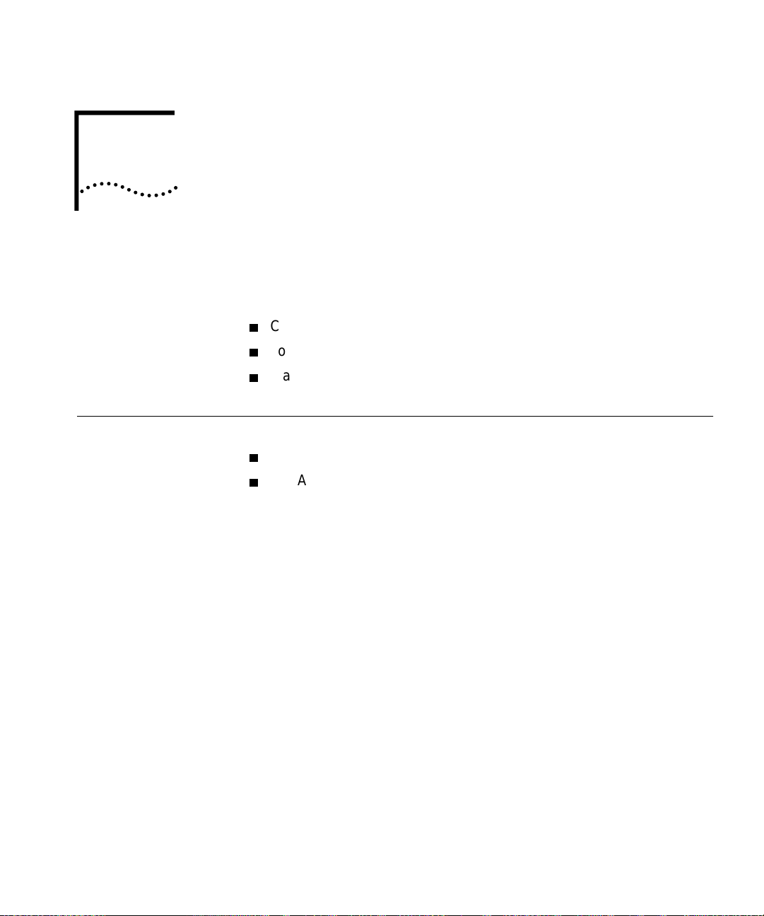
Enterprise Switch. The following topics are covered:
CoreBuilder 9000 ATM Enterprise Switch Characteristics
Software Release 3.0 Key Features
Standards and Protocols Supported
CoreBuilder 9000
ATM Enterprise
Switch
Characteristics
The ATM Switch
Fabric Module
The CoreBui lder 9000 ATM Enterprise Switch has two components:
The ATM Switch Fabric Module
The ATM Interface Module
For information about the ATM Interface Module, see the
Module User Guide
Guide
.
The ATM Switch Fabric Module has a switching capacity of 15 Gbps. The
high-performance, line-rate, non-blocking ATM Switch Fabric Module
features highly integrated ASICs that account for its scalable,
leading-edge performance and functionality. The module incorporates
on-board A TM control hardware for scaling the performance of Switched
Virtual Channel Connec ti on s (SVCs) and Swit che d V irtu al Path s (SV Ps).
and the
ATM Interface Module Getting Started
ATM Interface
Page 26
26
HAPTER
C
1: O
VERVIEW
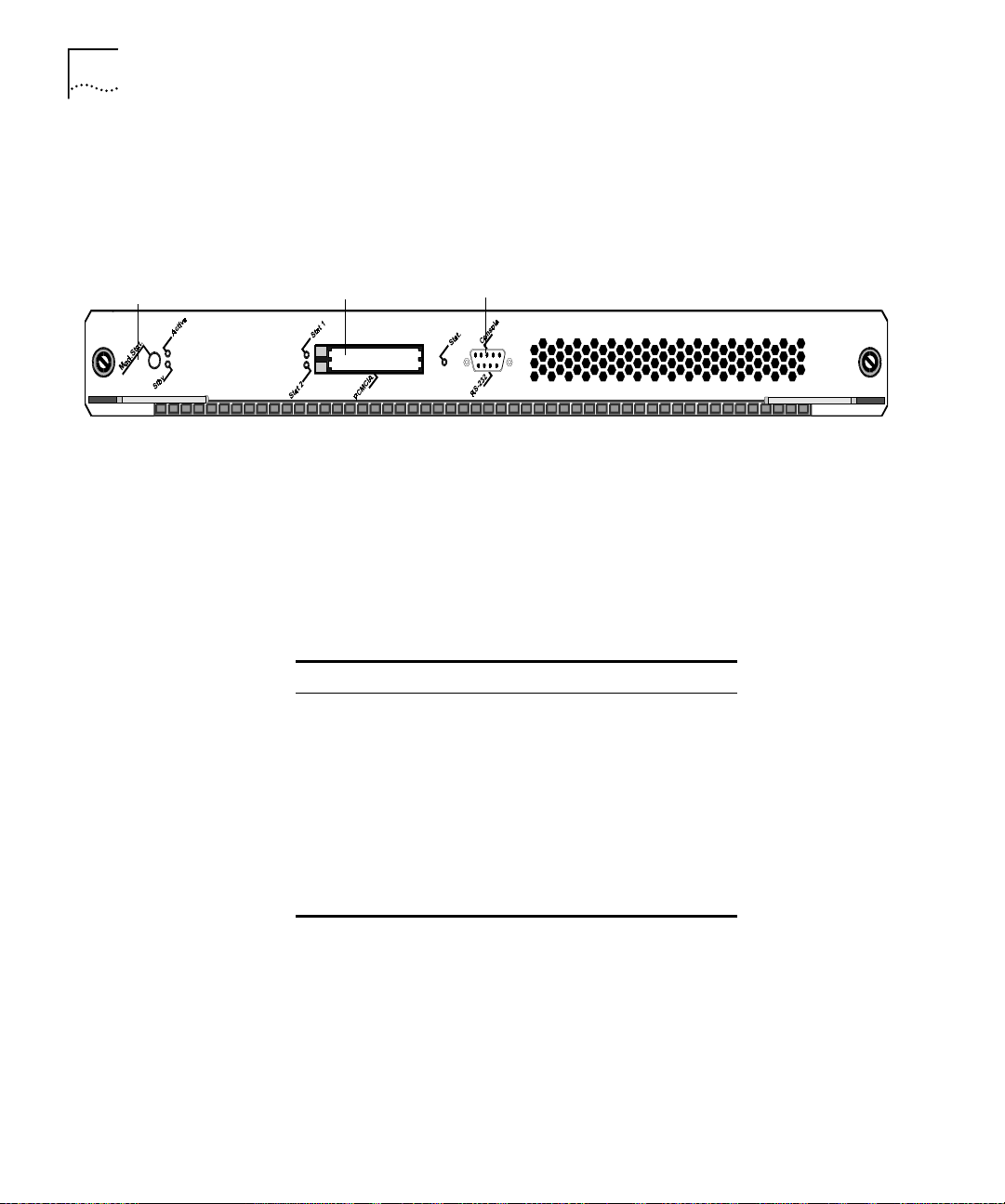
Figure 1 shows the front panel of the ATM Switch Fabric Module. Note
that, in the figure, the Module is shown on its side; in the 16-slot chassis
or the 8-slot chassis you install it vertically with the LEDs on top.
Figure 1 ATM Switch Fabric Module Front Panel
Module Status LED
Interfaces to ATM
LAN PC Card Slots
RS-232 Console Port
The Module Status LED indicates the ATM Switch Fabric Module’s status.
The dual PCMCIA slots have tw o indicator LEDs (one for each slot), and
the RS-232 consol e po rt ha s on e in di c at or LE D.
The CoreBuilder 9000 ATM Enterprise Switch provides wire-speed
interfaces for ATM OC-3c/STM-1, ATM OC-12c/STM-4, and
ATM 155 Mbps-over-UTP5 daughter cards, which are listed in Table 4.
Table 4 ATM Interfaces
Module Type No. of Ports Rate (Mbps)
OC-3c MMF
OC-3c SMF
OC-3c/STM-1 MM
OC-3c/STM-1 SM
OC-3c/STM-1 SM LR 2 155
OC-12c/STM-4 MM 1 622
OC12c/STM-4 SM IR 1 622
155 Mbps-over-UTP5 4 155
1MM = multimode
2SM = single mode
1
2
1
2
4 155
4 155
4 155
4 155
These cell-based daughter cards are designed to be installed into ATM
Interface Modules that are inserted into CoreBuilder 9000 chassis slots.
Each ATM Interface Module can accommodate two of the following
daughter cards in any combination: OC-3c/STM-1, OC-12c/STM-4, and
155 Mbps-over-UTP5.
Page 27

CoreBuilder 9000 ATM Enterprise Switch Characteristics
27
The OC-3c/STM-1 and OC-12c/STM-4 daughter cards are available in
single-mode or mu lti-mode. An OC-3c/STM-1 card is available with three
single-mode ports and one multi-mode port.
You can install up to 11 ATM Interface Modules in the 16-slo t chassi s and
up to 5 ATM Interface Modules in the 7-slot chassis and the 8-slot chassis.
You can order the ATM Interface Modules as a kit with daughter cards
included or, you can order individual daughter cards separately.
Table 5 lists the available configurations of the ATM Interface Module and
the daughter cards along with their part numbers.
Table 5 Daughter Cards Compatible with the ATM Interface Carrier Module
Card Type 3Com Part Number
OC-3c-MMF
OC-3c-SMF
OC-3c-SMLR
OC-12c-MMF 3CB9NAK1MC
OC-12c-SMF 3CB9NAK1SC
155 Mbps-over-UTP5 3CB9NAL4R
1MMF=Multi-Mode Fiber
2SMF=Single-Mode Fiber
3SMLR=Single-Mode Long Reach
1
2
3
3CB9NAL4MC
3CB9NAL4SC
3CB9NAL2SCLR
Processors
An on-board i960 processor handles all advanced software features
including SVC (Switched Virtual Circuit), signalling PNNI (Private Network
Node Interface), and SNMP (Simple Network Management Protocol)
management.
Page 28

28
HAPTER
C
1: O
VERVIEW
Device Management
Traffic Management
You can use the CoreBuilder 90 0 0 ATM Enterprise Switch Local
Management Application (LMA) or Transcend
®
Enterprise Manager (or
other SNMP-based net w ork management application) to manage your
CoreBuilder 9000 AT M Enterpri se Switch .
The CoreBui lder 9000 ATM Enterprise Switch LMA is a
character-oriented, menu-driven user interface for perform i ng
system-level administration. You operate this console from a terminal (or
terminal emulation software) or through a remote terminal protocol, such
as Telnet or Remote Login.
For more complete network management, use an external SNMP-based
application such as Transcend Enterprise Manager. Transcend provides
logical views and control for your network. In addition, it extends the
SNMP capabilities of the ATM Enterprise Switch with a common user
interface and easy-to-use administrative features that optimize network
configuration, oversight, and troubleshooting.
Traffic management in th e CoreBuilder 9000 ATM Enterprise Switch is
done at two levels:
Preventing congestion
Handling congestion
Mechanisms for Preventing Congestion
The following flow control mechanisms for automatic management in
the CoreBuilder 9000 ATM Enterprise Switch Fabric Module work to
prevent cell and frame loss under intense loads:
Explicit Forward Cong est i o n In di ca tion (EFCI) Marki ng
Call Admission Control
Flow Control
CLP bit tagging support
Priorities
Scheduling
Page 29

CoreBuilder 9000 ATM Enterprise Switch Characteristics
Mechanisms for Handling Congestion
The following mechanism s are used to manage congestion in the
CoreBuilder 9000 ATM Enterprise Switch Fabric Module:
Back Pressur e
Partial Packet Drop (PPD) (Hardware ready)
Early Packet Dr op (EPD) (Hardware ready)
Call Admission
CLP-based Cell Discard.
29
ATM Networks
The CoreBui lder 9000 ATM Enterprise Switch supports the following
types of ATM network s:
Classical IP (CLIP) ATM
The CoreBui lder 9000 ATM Enterprise Switch is transparent to CLIP and
allows you to use CLIP over the ATM network. For a view of th e
CoreBuilder 9000 ATM Enterprise Switch when CLIP is used over ATM
within a network, see Chapter 3, ATM Network Basics in the Operations
Guide.
Virtual Networks
The CoreBui lder 9000 ATM Enterprise Switch handles virtual networks
across the enterprise using ATM and LAN Emulation (LANE). Segments in
a virtual network can incorporate legacy LANs and ATM devices using
LANE, allowing you to organize network users into logical groups,
regardless of their physical location. Using this feature, you can set up
workgroups compr ised of members fr om various departments or bu siness
units around the enterprise, and centralize servers into server
farms
for
better administration. For more informati o n abo ut virtu a l netwo rks, see
Chapter 3, ATM Network Basics in the Operations Guide.
Page 30

30
HAPTER
C
1: O
VERVIEW
Software Release
3.0 Key Features
The CoreBuilder 9000 ATM Enterprise Switch has the following key
features:
Distributed output buffering
An AT M switching engine that provides full-rate, non-blocking
switching for up to 22 OC-12c/STM-4 ATM ports and up to 88
OC-3c/STM-1 155 Mbps SONE T/SDH ports
A self-ro uting swi tchi ng ar chite cture built on top of an 560 Gbps (f ullduplex) passive backplane that meets demands for higher port density,
faster data speeds, and scalability
Seamless, full-rate multicast support
Cell Loss Priority (CLP) support for congestion management. Dynamic
threshold mech anism for CLP, EFCI marking ready, EPD hardware
ready, PPD hardware ready
A back pressure control mechanism
Policy support VCI/VPI (Hardwar e ready)
4096 VCs for each OC-3c port; 4096x4 for each OC-12c port
Two levels of priority, dynamic allocation of cell buffer priority and
scheduling capa bility per priority pe r po rt
Switch Management via PCMC IA card wit h terminal connect ion status
indicator
Management Features
SNMP, Telnet, and Transcend Enterprise Manager
Multiple agents with single management entry point
RMON and RMON2
Statistics Ga the r i ng an d Reporting
Management Interfaces
10BASE-T (RJ-45) Eth ernet
RS-232 (DB-9) control port
Management Applications
TranscendWare management applications software
Terminal emulation (local)
Page 31

Standards and Protocols Supported
MIBs Supported — MIB II, AToM MIB, RMON MIB, Interface Evolution
MIB, NCDCHASS MIB (private)
ATM Forum Standards Compliance
Electromagnetic Compatibility — FCC Part 15, EN50081-1 (EN55022
Class B); EN50082-1 (IEC 801-2, IEC 801-3, IEC 801-4)
Safety — EN60950, UL1950, CSA22.2, TUV, IEEE 825-1, 852-2; PCB
UL94V-O; PCB; ANSI/IEEE; RB-276 Class 2
31
Standards and
Protocols
Supported
Protocols
ATM
This section describes the major standards and protocols used within the
CoreBuilder 9000 ATM Enterprise Switch and the network applications
and topologies that you can use.
The CoreBui lder 9000 ATM Enterprise Switch uses ATM technology,
including connect ion protocol s, user -to-netwo rk and network-t o-network
interfaces. You can directly control all features via devic e management.
For more information about ATM, see Chapter 3,
ATM Network Basics
in
the Operations Guide.
The CoreBuil der 900 0 ATM Enterprise Switch use s numer ous pr ot ocol s to
connect to and communicate with other devices in the network. Among
the protocols used is the Integrated Local Management Interface (ILMI),
which is used to connect over the user-to-network interface (UNI) and
network-to-network interface (NNI), as well as for address registration.
Signalling (Q2931) for Switched Virtual Connection (SVC ) is used for
dynamically managing calls. IISP, E-IISP are implemented for multiple
switch networks.
Communications Protocols — RFC 826 ARP, RFC 791 IP, RFC 792
ICMP, RDC 768 UDP, RFC 793 TCP
Ethernet Protocols — IEEE 80 2. 1d , IE EE 80 2.3
Management Protocols — RFC 1157 SNMP, RFC 1212 Concise, RFC
1213 MIB II, RFC 1212 Traps.
Page 32

32
HAPTER
C
1: O
VERVIEW
Page 33

2
TARTING
S
U
P
Safety Precautions
This chapter contains a description of the system states of the
CoreBuilder
Topics covered in this chapter include:
Safety Precautions
Handling Precautions
Précautions de Sécurité
Précautions de Manipulation
Sicherheitsvorkehrungen
Vorkehrungen beim Umgang mit dem Modul
Installation
For information ab o ut in st a lli n g the ATM Switch Fabric Mod ul e , see the
CoreBuilder 9000 ATM Switch Fabric Module Getting Started Guide
When you handle components in a CoreBuilder 90 00 system, be sure
that you follow all safety precautions. To avoid electric shocks, burns, fire
or equipment damage, read and follow these warnings:
WARNING
Use extreme caution when yo u install, remove , or replace t he A TM Switch
Fabric Module.
®
9000 ATM Switch Fabric Module and its daughter cards.
.
: Hazardous energy exis ts within the CoreBu ilder 9000 system.
WARNING
or replaced only by trained service personnel.
The ATM Switch Fabric Module must be installed, removed,
:
Page 34

34
HAPTER
C
2: S
TARTING UP
Laser and LED Safety
Information
ESD Safety
Information
WARNING:
When the CoreBuilder 9000 system is on, never insert metal
objects, such as a screwdriver into op en module slots and be sure to
remove all hand-worn jewelry (such as watches and rings). When the
system is on, do not touch any connections within the chassis with your
fingers. Do not insert metal objects into the backplane.
WARNING:
Do not plug in, turn on, or attem pt to op er a te an ob vio usl y
damaged module.
WARNING
: To ensure optical safety when you install the ATM Switch
Fabric Module, comp ly with this precaution:
Although the data communications LEDs and lasers that are used in this
product meet the regulatory requirements for casual exposure to the eye,
as with any bright source of bright light, 3Com recommends that you do
not look into the light source (Class One Laser/LED Product).
Electrostatic Discharge (ESD) can damage components on the module.
ESD, which occurs when the module is handled improperly, can cause
complete or intermittent failure.
CAUTION:
To prevent ESD-related damage:
Handling Precautions
Make sure that you are properly grounded. Use a footstrap and a
grounded mat, or wear a grounded wrist strap, ensuring t hat the
strap makes good skin contact.
Keep the module in its anti static bag until you are ready to install it.
Observe the follo w in g preca u tio ns whe n yo u ha n dl e th e ATM Switch
Fabric Module:
Always handle the module by the front panel or as shown in the
Switch Fabric Module Getting Started Guide
Do not touch the components, pins, leads, or solder connections.
Before you push the module into the chassis, make sure that the
.
ATM
module ejector handles are open.
When you insert the module into the chassis , ma tch the up pe r and
lower/left and right module guides.
When you insert the module into the chassis module guides, do not
twist or otherwise force the module into the chassis.
Page 35

Précautions de Sécurité
35
Précautions de
Sécurité
Lorsque on manipule les éléments du système CoreBuilder 9000, il faut
bien respecter les précautions de sécurité. Pour éviter des décharges
électriques, des brûlures, des incendies ainsi que pour ne pas
endommager l’équipement, veuillez bien lire et respecter les précautions
suivantes:
AVERTISSEMENT:
Le système CoreBuilder 9000 contient énergie qui
peut s’avérer dangereuse. Soyez très minutieux lor sque vous installez,
enlevez ou remplacez un Module de Switch Fabric ATM.
AVERTISSEMENT:
Le Module de Switch Fabri c ATM ne doit être install é ,
enlevé ou remplacé que par personnel qualifié.
AVERTISSEMENT:
Lorsque le système CoreBuilder 900 0 est sous tensi on,
ne jamais insérer d es objets te ls que tou rnevis ni mêm e des doi gts portant
des bijoux dans l’emplacement d’un module ouvert. Lorsque le système
est sous tension, ne t ouchez aucune connexion du châssis avec les mains
ou les doigts. Ne pas insérer d’objets métalliques dans la face arrière.
AVERTISSEMENT:
Ne pas brancher, allumer ou essayer de mettre en
fonctionnement un module évidemment défectueux.
AVERTISSEMENT:
Pour vous protéger les yeux lors de l’installation du
Module de Switch Fabric ATM, respectez les précautions suivantes:
Information sur la
Prévention de
Décharges
É
lectrostatiques
Bien que les LEDs et lasers des communications de données utilisés dans
ce produit soient conformes aux normes d’exposition oculaires
éventuelle, 3Com vou s recomma nde , co mme pour tout e lumi ère vi ve, de
ne pas regarder directement la source de lumière.
Les décharges électrostatiques peuvent endommager des élé ments du
module. Ces décharges, qui surviennent lors d’une manipulation
inadéquate du modul e, peuvent entraîner une défaillance temporaire ou
permanente.
ATTENTION:
Assurez-vous d’être bien branché à la terre. Utilisez un sous-pied et un
Pour éviter des dommages électrostatiques:
tapis relié à la terre ou portez un bracelet mis à la terre, et veillez à ce
que le contact dermique soit bon.
Conservez le module dans un sac antistatique jusqu’à son installation.
Page 36

36
HAPTER
C
2: S
TARTING UP
Précautions de Manipulation
Sicherheitsvorkehru ngen
Respectez les précauti ons suiv antes lor sque vous ma nipulez l e Modul e de
Switch Fabric ATM:
Tenez le module par son panneau avant ou comme indiqueé dans le
ATM Switch Fabric Module Getting Started Guide
Ne touchez pas les éléments, broches, branchements ou soudures.
Avant d’insérer le module dans le châssis, assurez-vous que les
.
poignées d’insertion/d’ éjection sont ou v ertes.
Lorsque vous faites glisser le module dans le châssis, faites coïncider
les rails inférieurs et supérieurs/à gauche et à droite.
Ne jamais forcer lorsque vous insérez le module dans les rails.
Halten Sie beim Umgang mit Modulen des CoreBuilder-9000-Systems
unbedingt alle Si cherheitsvorkehrungen ein. Lesen und befolgen Sie
folgende Warnungen, um elektrische Schläge, Verbrennungen, Brände
oder Materialschäden zu vermeiden:
WARNUNG:
Im CoreBuilder 9000-System existieren hohe elektrische
Spannungen. Sie soll ten deshalb das ATM-Modul nur mit äußerster
Vorsicht installieren, entfernen oder tauschen.
WARNUNG:
Das ATM-Modul darf nur von ausgebildetem
Servicepersonal installiert, entfernt oder getauscht werden.
WARNUNG:
Führen Sie bei eingeschaltetem CoreBuilder-9000-System
niemals Metallgegenstände wie Schraubenzieher oder Schmuck an
Fingern in offene Modulschlitze ein. Be rühren Sie bei eingeschaltetem
System keine Verbindungsstellen in Gerät mit Händen oder Fingern.
Setzen Sie keine Met a llgegenstände in die Rückwand ein.
WARNUNG:
Vers uchen Sie nicht, ein offensichtlich beschädigtes Modul
zu installieren oder in Betrieb zu setzen.
WARNUNG:
Halten Sie sich beim Installieren des
A TM-Schnittstellen-Moduls zur Gewährleist ung des optischen Sicherheit
an folgende Vorkehrung: Obwohl die für die Datenkommunikation
verwendeten LEDs und Laser-Dioden die Sicherheitsvorkehrungen für
zufälligen Augenkontakt erfüllen, entsprechend wie bei anderen hellen
Lichtquellen, em pfiehlt 3Com nic ht di re kt in die Li ch tq ue l le n z u bl ic k en .
Page 37

Vorkehrungen beim Umgang mit dem Modul
37
Sicherheitsinfor-
mationen für
Elektrostatische
Entladungen
V orkehrungen beim
Umgang mit dem
Modul
Elektrostatische Entladungen (ESD) können einzelne Baugruppen oder
das gesamte Modul beschädigen. ESD können vorkommen, wenn das
Modul nicht richt ig gehandhabt wird und können eine dauerhafte oder
zeitweilige Fehlfunktion bewirken.
VORSICHT:
V ergewissern Sie sich, daß Sie richtig geerdet sind. Benutz en Sie ein
Zur Verhütung von Schäden durch ESD:
Fußband und eine geerdete Matte oder tragen Sie ein geerdetes
Handgelenkband mi t gutem Hautkontakt.
Lassen Sie das Modul bis zur Installation in der Anti-Statik-Tasche.
Beachten Sie folgende Vorkehrungen beim Umgang mit de m
ATM-Schnittstellen-Modul:
Fassen Sie das Modul immer nur an der Frontplatte an, oder wie in
ATM Switch Fabric Module Getting Started Guide
dem
Berühren Sie nicht die Baugruppen, Stifte, Leitu ngen oder
gezeigt.
Lötverbindungen.
V ergewissern Sie sich vor dem Einschieben des Moduls, daß die
beiden Bügel zum Einschieben bzw. Entfernen offen st ehen.
Achten Sie beim Einschieben des Moduls darauf, daß es sich in der
oberen und unteren/rechten und linken Fü hrungsschiene befindet.
Achten Sie beim Einschieben des Moduls darauf, daß Sie es nicht
verkannten. Schiebe n Sie das Module nicht mit Gewalt in das Gerät.
Page 38

38
HAPTER
C
2: S
TARTING UP
Installation
Installation
Prerequisites
This section describes installing the ATM Switch Fabric Module.
Before you install the ATM Switch Fabric Module, ensure that you have
met all of the following prerequisite conditions:
Complete the chassis unpacking and installation procedure as described
1
Chassis Quick Installation
in the
Guides. You can install the chassis in a
rack, on a shelf, or on a tabletop.
Install the power supply as described in the
2
Guides and install the power cable as described in the
Power Supply Installation
Enterprise
Management Engine Quick St art Guide for the
CoreBuilder 9000 Enterprise Switch.
Install the Enterprise Management Engine as descr ibed in the
3
Enterprise
Management Engine Quick St art Guide for the CoreBuilder 9000
Enterprise Switch
Install the ATM Switch Fabric Module as described in the
4
.
CoreBuilder 9000 ATM Switch Fabric Module Getting Started Guide
Read the
5
CoreBuilder 9000 ATM Interface Module Getting Started Guide
to make sure that you have all of the required components to get your
system up and running and that you have completed all of the
prerequisite work.
To manage the ATM Interface Module and CoreBuilder 9000 ATM
6
Enterprise Switch through the Simple Network Management Protocol
®
(SNMP), you must install the 3Com Transcend
Enterprise Manager for
UNIX or for Windows NT.
Installing the
Daughter Cards
Installing the ATM
Interface Module into
the Chassis
For complete details on how to install the daughter cards into the A TM
Interface Module, see the
Getting Started Gu
CoreBuilder 9000 ATM Interface Module
ide.
For complete details on how to install the ATM Interface Module into the
CoreBuilder 9000 chassis, see the
Module Getting Started Guide
CoreBuilder 9000 ATM Interface
.
Page 39

3
NTEGRATED FAST
I
S
ETUP
CoreBuilder 9000 ATM Enterprise Switch Integrated Fast Setup
This chapter describes how t o use the I nteg rat ed Fast Setu p procedure to
configure the C oreBuilder
function in the network.
After you have physically connected th e CoreBuilde r 90 0 0 ATM
Enterprise Switch to your site network devices and power has been
applied, you must set some parameters to enable the CoreBuilder 9000
ATM Enterpri se Switch with its attach ed ATM Interface Modules to
function in the network.
The CoreBuild er 9000 ATM Enterprise Switch local manageme nt software
features an Integrate d Fa s t Se t u p procedure that c on f ig ures the
CoreBuilder 9000 ATM Enterprise Switch in one continuous process.
With Integrated Fast Setup, you can set up the most important system
parameters that you need to start working right away. The remaining
parameters are assigned default values.
If you are installing the ATM Switch Fabric Module and ATM Interface
Modules at the same time, you need to per form the Integra ted Fast Setup
procedure only once; all mod u le s wi ll be co n f ig u red.
®
9000 ATM Enterprise Switch, allowing it to
Page 40

40
HAPTER
C
NTEGRATED FAST SETUP
3: I
Setup Procedure
Sections
Entering Data
Table 6 lists the steps or sections of the Integrated Fast Setup.
Table 6 Integrated Fast Setup Procedure Sections
Setup Section Description
1
Routing Mode
2
Network Prefix
3
PNNI Parameters
4
LE Parameters
5
LECS Address
6
UNI/NNI parameters
7
IP and Management
Configuration
8
Confirmation
Set the Routing Mode (EIISP or PNNI) for the
CoreBuilder® 9000 ATM Enterprise Switch
Set Network Prefix for the CoreBuilder 9000 ATM
Enterprise Switch
Set PNNI parameters for the CoreBuilder 9000 ATM
Enterprise Switch
Set LE parameters for the CoreBuilder 9000 ATM
Enterprise Switch
Set active LECS address for the CoreBuil de r 90 00 ATM
Enterprise Switch
Set UNI/NNI port parameters for ports in the ATM
Interface Module
Set IP address of the switch, address of the NMS
application, de fault gateway address, and subnet mask
Confirm setup operation
The Integrated Fast Setup procedure runs sequentially through the
relevant data for all of the sections, displaying a prompt for each data
item and a default value. If you want to change the default, enter a
different value in place of the default. If you want to accept the default,
press Enter.
Navigation Aids
Integrated Fast Setup
Operation
Table 7 lists the shortcut characters that you can use to move betwee n
sections of the Inte gra t e d Fast Set up proced u re:
Table 7 Integrated Fast Setup Procedure Navigation Aids
Type To Go
< Back to previous section
> To next section
>S To section indicated by double underlined ID letter S in section title
\ Back to begin ning of setup
$ To end of setup
For step-by-step instructions, see the
CoreBuilder 9000 ATM Switch
Fabric Module Gett ing Started Guide.
Page 41

SING THE LOCAL
U
ANAGEMENT
M
4
Management Capabilities
PPLICATION
A
This chapter describes how to use the CoreBuilder® 9000 AT M Enterprise
Switch Local Management Application (LMA) to configure and administer
the CoreBuilder 9000 ATM Enterprise Switch. A Menu Index shows the
command structur e of the LMA and refers to th e command description
for each menu command. You run the LMA from a terminal via a direct
RS-232 connection or via Telnet.
Use the LMA to configure your CoreBuilder 9000 ATM Enterprise Switch.
To augment network management, you can use an external applica tion,
such as 3Com’s Transcend
LMA functions include:
Platform administration
LAN Emulation administration
ATM Connections administration
®
Enterprise VLAN Manager.
Starting Up
Statistics di splay
Testing & Diagnostics administration
To log in to the LMA, you need:
The desired access leve l
Your passw o rd
Page 42

42
HAPTER
C
SING THE LOCAL MANAGEMENT APPLICATION
4: U
LMA Access Level
Logging In
The LMA has three levels of access: read access, write access, and
administer access. Each le vel grants diffe rent access privileges and is
suited to a different type of user. Table 8 lists the privileges granted for
each access level.
Table 8 Access Levels
Access Level Privileges
Read Read-only privi leg e
Write Right to make local changes to LMA. No right to change
passwords or parameters that affect the global network.
Admin All privileges
When you boot the system, the following login screen appears:
-------------------------------
- CoreBuilder 9000 -
- -
- ATM Enterprise Switch -
------------------------------Access level (read, write, admin):
Password:
When you log in for the first time, simply press Enter at the Password
prompt.
CAUTION
: 3Com strongly recommends that you change passwords for
security reasons. For more information, see “Example — Changing a
Password” on page 45.
Page 43

To log in to the LMA:
Starting Up
43
Enter your access level (default is
1
Enter your password. After a successful login, the Main Menu is displayed
2
admin
).
as shown in Figure 2.
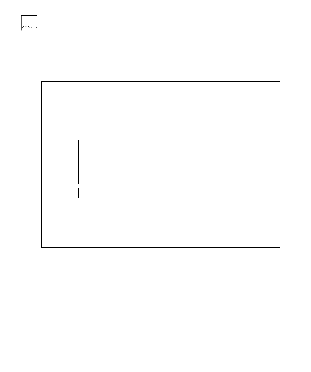
Figure 2 LMA Main Menu
CB9000 switch module - Main Menu:
(1) SYS: Platform Configuration ->
(2) LEM: LAN Emulation ->
(3) CON: Connections ->
(4) STS: Statistics ->
(5) DIA: Testing and Diagnostics ->
(6) FTR: ATM Features
(7) LOG: Logout
(8) VER: Version
(9) FST: Fast Setup
Page 44

44
HAPTER
C
SING THE LOCAL MANAGEMENT APPLICATION
4: U
The LMA Menu System
The LMA menu system is a set of command menus that are organized in
a hierarchical, top-down fashion. Figure 3 shows the menu structure.
Each command menu contains a numbered list of menu items. Each
menu item has a three-letter mnemonic identifier and a short description
of the item. There are two kinds of menu items: commands that display
another, lower-level, command menu (
submenu
) and commands that
perform a specific administrative task. The submenu command is
distinguished by the arrow (
->
) on the right.
The Main Menu is at the top of the hierarchy. Through it, you access the
submenus for the main topics of management such as Platform
Configuration , LAN Emulation, an d Co nn e c tio ns. Figure 3 shows the
Main Menu and some of its successive submenus.
Figure 3 LMA Menu Structure
CB9000 Switch Module - Main Menu:
(1) SYS: Platform Configuration ->
(2) LEM: LAN Emulation ->
(3) CON: Connections ->
(4) STS: Statistics ->
(5) DIA: Testing & Diagnostics ->
(6) FTR: ATM features
7
) LOG: Logout
CB9000 Switch Module - Platform Configuration Menu:
(1) SET: Switch Setup ->
(2) RES: Set all Configurations to Factory Defaults
(3) LOA: Download System Software ->
(4) SWM: Switch Modules
(5) IFC: Interface cards ->
(6) FLS: Configuration Flash Status
(7) RBO: Reboot
CB9000 Switch Module - Switch Setup Menu:
(1) PAS: Password Setup ->
(2) MNG: Management Setup ->
(3) NNI: NNI Setup ->
(4) SIG: Signaling Setup ->
(5) SLE: LE Setup ->
(6) SNP: Switch Network Prefix Setup ->
(7) FCI: EFCI Threshold Setup ->
(8) IME: ILMI Setup ->
Page 45

The LMA Menu System
45
Selecting Menu
Options
Example — Changing
a Password
To select a menu option, you enter its num be r or its mnemonic identi fier
at the prompt symbo l (
>
) that is displayed below the menu item list. You
need to enter the first unique characters of the mnemonic identifier.
The hierarchi c al path from the Main Menu down to the currently
displayed submenu option is displayed in front of the angle bracket
prompt. This convention helps you orient yourself in the menu hierarchy.
To illustrate how to work with the menu system, the example in this
section changes the read-access password. This example is shown in
Figure 3. The following command description guides you through the
execution of the command. It specifies the menu sequence to ent er, the
parameters to enter and their format, the command r esults, and any
system messages. A similar comma nd description format is provided for
each command in this manual.
Entering the Menu Sequence
First, enter the menu sequence in the order shown in section A of the
“Command Description” on page 18 in the About This Guide section. In
this example, you enter the menu item numbers, but you can enter the
three-letter mnemonic code instead.
At the Main Menu prompt, enter
1
.
1
The Platform Configuration Menu is displayed (the second screen in
Figure 3), followed by the path
At the Platform Configurati on Me nu prompt, enter
2
(1) SYS
: and the (>) prompt.
.
1
The Switch Setup Menu submenu is displayed (the third screen in
Figure 3), followed by the path
At the Switch Setup Menu prompt, enter
3
(1)SYS\(1)SET
1
and the (>) prompt.
.
Page 46

46
HAPTER
C
SING THE LOCAL MANAGEMENT APPLICATION
4: U
The Password Setup Menu is displayed as follows, followed by the path
(1)SYS\(1)SET\(1)PAS
and the (>) prompt. These menu items are all
configuration commands; none of them have arrows to the right.
CB9000 switch module - Password Setup Menu:
(1) REA: Set Read-access Password
(2) WRI: Set Write-access Password
(3) ADM: Set Admin-access Password
(4) PAS: Set Password Config to factory defaults
[ '\' -Main, '-' -Back in menus]
(1)SYS\(1)SET\(1)PAS>1
At the Password Se tup Menu prompt, enter
4
1.
The prompt for the new read password is displayed as follows:
Enter the new read password:
This completes the menu sequence.
Entering the Command Parameters
Now refer to section B in the “Command Description” on page 18. This
section explains which parame te rs to ente r and th e for mat to use.
5
At the
Enter the new read password:
prompt, enter the new
password in a format of up to eight alphanumeric characters.
Direct Access to
Submenus
6
At the
Enter the new read password again:
prompt, enter the new
password agai n ex a c tl y as before.
Command Results
After the command executes successfully, a system message is displayed:
The password has been changed.
The command results and syst ems messages are shown in section D in
“Command Description” on page 18 in the About This Guide section.
You can display a submenu or execute a command directly without
having to step down through the hierarchy as in the previous example. At
the Main Menu prompt, type the required sequence of menu item
numbers or menu it em mne moni c fo ll owed by the comma nd par am eters
all on one line, sep arated by sp acebar st r okes. For exampl e, to display th e
password pr ompt dir ect ly fr om the Ma in Menu , just en ter
1 1 1 1
Main Menu prompt.
at the
Page 47

The LMA Menu System
47
Entering Multiple
Parameters
Quick Key Functions
When a command has more than one parameter, you can enter them all
on the same command line with blan ks in between or you can enter
some or all of them on separate command lines. If you do not enter them
all on one line, you are repeatedly prompted for the remaining
parameters.
If you enter an illegal char acter or string (such as an out-of-range
parameter), the LMA display responds with an error message which is
indicated by a three-asterisk (***) prefix.
The following quick key functions are available when you work with the
management menus. Table 9 lists functions for navigating in the menu
system; Table 10 lists aids for editing parameters.
Table 9 Menu Navigation Functions
To go Type or Press
To the Main Me nu from any point \
To the previous menu Back and forth within the command line Left/Right Arrows
To the beginning of the command line Home
To the end of the command line End
Table 10 Editing Aids
To perform this task Type or Press
Clear the value of the parameter that you just entered <
Clear the values of all the parameters in the list that you
just entered
Retrieve a previous command Up arrow
Get the next command Down arrow
Delete the character that precedes the insertion point Backspace
Delete the character that follows the insertion point Del
Toggle between Insert and Overwrite modes Ins
Clear the command line 5
Escape from prompt $
>
Page 48

48
HAPTER
C
SING THE LOCAL MANAGEMENT APPLICATION
4: U
Logging Out
To log out of the LMA, ente r
at the Main Menu prompt.
7
Automatic Logout
The CoreBuilder 9000 ATM Enterprise Switch has an automatic logou t
feature. If you do not use the keyboard for 15 minutes, the ATM Switch
Fabric Module automatically logs you out. You cannot adjust the length
of time or disable this feat ure.
Page 49

5
ONFIGURING THE
C
LATFORM
P
This chapter describes how you configure common management tasks
for the CoreBuilder
description of the login procedure, see “Logging I n” on page 42.
Password Setup
Setting Up for Management
Setting the Port Network Conn ect io n Typ e
Resetting All Parameters
Downloading System So ft w a re
Managing Switch Fabric Mo d ul es
Configuring Interface Modules
Logging Out and Rebooting
AT M Fe atures and Software Versions
LECS ATM Address
Setting Up the Switch Clock Source
Setting Up for PNNI
®
9000 ATM Enterprise Switch platform. For a
Page 50

50
HAPTER
C
ONFIGURING THE PLATFORM
5: C
Password Setup
You can set up the three levels of access passwords to the LMA, or reset
all passwords to their factory defaults.
CAUTION
: 3Com strongly recommends that you change passwords for
security reasons.
Three access passwords are provided: read-access, write-access and
admin-access. For normal a dmi nistra tive o pera tion, u se the admi n-a ccess
password. For mor e information on access levels, see “LMA Access Leve l”
on page 42.
In the password setup submenu, you have the following options:
Update Read-access Password
Update Write-access Passwor d
Update Admin-access Password
Set Password to Factory Default
Page 51

Password Setup
51
Update Read-access
Password
Update the read- access password. Enter the new password a second
time.
To accept the default password, press Enter.
Command Actions
Enter menu sequence:
Enter a parameter at the prompt
Parameter Format or Range
New password 0 to 8 alphanumeric characters
New password
confirmation
Direct access sequence:
(1) SYS: Platform Configuration
(1) SET: Switch Setup
(1) PAS: Password Setup
(1) REA: Set Read-access Password
Enter the password exactly as you did before.
1 1 1 1
Command Result
System action t aken:
System message display:
The read-access password is updated.
The password has been changed.
Example
Enter:
1 1 1 1
The following dialog is display ed. Note tha t the passwor ds themselv es ar e
not displayed.
Enter the new read password:
Enter the new read password again:
The password has been changed.
mypassw
mypassw
The read-access password is updated.
Page 52

52
HAPTER
C
ONFIGURING THE PLATFORM
5: C
Update Write-access
Password
Update the write-access password. Enter the new password a second
time to confirm your entry.
To accept the default password, press Enter.
Command Actions
.
Enter menu sequence:
Enter a parameter at the prompt
Parameter Format or Range
New password 0 to 8 alphanumeric characters
New password
confirmation
Direct access sequence:
(1) SYS: Platform Configuration
(1) SET: Switch Setup
(1) PAS: Password Setup
(2) WRI: Set Write-access Password
Enter the password exactly as you did before.
1 1 1 2
[parameters]
Command Result
System action t aken:
System message display:
The write-access password is update d.
The password has been changed.
Example
Enter:
1 1 1 2
The following dialog is display ed. Note tha t the passwor ds themselv es are
not displayed.
Enter the new write password:
Enter the new write password again:
The password has been changed.
mypassw
mypassw
The write-access password is updated.
Page 53

Password Setup
53
Update Admin-access
Password
Update the admin-access password. Enter the new password a second
time to confirm your entry. You are prompted for the existing password
before you enter the new password.
To accept the default password, press Enter.
Command Actions
Enter menu sequence:
Enter a parameter at the prompt
Parameter Format or Range
Old password Enter the old password.
New password 0 to 8 alphanumeric characters
New password
confirmation
Direct access sequence:
(1) SYS: Platform Configuration
(1) SET: Switch Setup
(1) PAS: Password Setup
(3) ADM: Set Admin Password
Enter the password exactly as you did before.
1 1 1 3
[parameters]
Command Result
System action t aken:
System message display:
The admin-access password is updated.
The password has been changed.
Example
Enter:
1 1 1 3
The following dialog is display ed. Note tha t the passwor ds themselv es ar e
not displayed.
Enter the old admin password:
Enter the new admin password:
Enter the new admin password again:
The password has been changed.
oldpass
newpass
newpass
The admin-access password is updated.
Page 54

54
HAPTER
C
ONFIGURING THE PLATFORM
5: C
Set Password to
Factory Default
Reset the passwords to their factory default settings for the
CoreBuilder 9000 ATM Enterprise Switch. These are, for each type of
user: read access, write access, and administer access. For more
information on access levels, see the
Module Getting Started Guide
CoreBuilder 900 0 A TM Switch F abric
.
To accept the default password, press Enter.
Command Actions
Enter menu sequence:
Enter a parameter at the prompt
Parameter Format or Range
Confirm reset
Direct access sequence:
(1) SYS: Platform Configuration
(1) SET: Switch Setup
(1) PAS: Password Setup
(4) PAS: Set Password configuration
to factory defaults
or
y
n
1 1 1 4
[parameters]
Command Result
System action t aken:
System message display:
The passwords are reset to their factory default values.
Password configuration was set to
defaults.
Example
Enter:
1 1 1 4
The following prompt is displayed:
Do you really want to reset config? [y/n]
Enter y to confirm. The following message appears:
Password configuration was set to defaults.
The passwords are reset to their factory values.
Page 55

Setting Up for Management
55
Setting Up for
Management
You can set up and display parameters for remotely managing the
CoreBuilder 9000 ATM Enterprise Switch. The CoreBuilder 9000 ATM
Enterprise Switch needs these parameters to com mu ni cate via the
network.
Display Current IP Configuration
Update IP Address
Display Current NMS IP Address
Update NMS Address
Display Current Default Gateway IP Address
Update Default Gateway IP Address
Display Current IP Subnet Mask
Update IP Subnet Mask
Display Current Read Community String
Update Read Community String
Display Current Write Community String
Update Write Community String
Display Ethernet Encapsulation Type
Update Ethernet Encapsulati on Type
Set Management Configuration to Factory Defaults
Page 56

56
HAPTER
C
ONFIGURING THE PLATFORM
5: C
Display Current IP
Configuration
Display the current IP address of the CoreBuilder 9000 ATM Enterprise
Switch.
Command Actions
Enter the menu sequence:
Direct access sequence:
(1) SYS: Platform Configuration
(1) SET: Switch Setup
(2) MNG: Management Setup
(1) SIP: IP Setup
(1) GIP: Get IP Address
1 1 2 1 1
Command Result
System action t aken:
System message display:
The current IP address is displayed.
Current IP address:
Example
Enter:
1 1 2 1 1
The following me s s a g e is di s pl ay e d :
Current IP address: 151.104.78.86
The current IP address is displayed.
Page 57

Setting Up for Management
57
Update IP Address
Update the IP address of the CoreBuilder 9000 ATM Enterprise Switch.
The default factory IP address is
0.0.0.0.
The IP address is changed after the next reboot.
Command Actions
Enter the menu sequence:
Enter a parameter at the prompt
Parameter Format or Range
IP Address V alid IP address
Direct access sequence:
(1) SYS: Platform configuration
(1) SET: Switch setup
(2) MNG: Management setup
(1) SIP: IP Setup
(2) SIP: Set IP Address
1 1 2 1 2
[parameters]
Command Result
System action t aken:
System message display:
The IP address is updated.
IP address was successfully set for
next reboot.
Example
Enter:
1 1 2 1 2 100.0.2.2
The following me s s a g e is di s pl ay e d :
IP address was successfully set for next reboot.
The IP address is updated to 100.0.2.2 and takes effect after the next
reboot.
CAUTION:
Make sure to change the factory default IP address to a valid
IP address that matches your network IP addresses.
Page 58

58
HAPTER
C
ONFIGURING THE PLATFORM
5: C
Display Current NMS
IP Address
Display the current NMS IP address where the CoreBuilder 9000 ATM
Enterprise Switch sends event traps.
Command Actions
Enter the menu sequence:
Direct access sequence:
(1) SYS: Platform Configuration
(1) SET: Switch Setup
(2) MNG: Management Setup
(2) NMS: NMS Setup
(1) GNS: Get NMS Address
1 1 2 2 1
Command Result
System action t aken:
System message display:
Current NMS IP address is displayed.
Current NMS address:
Example
Enter:
1 1 2 2 1
The following me s s a g e is di s pl ay e d :
Current NMS address: 151.104.78.75
The current NMS IP address is displayed.
Page 59

Setting Up for Management
59
Update NMS Address
Update the NMS IP address where the CoreBuilder 9000 ATM Enterprise
Switch sends the event traps. The factory default NMS address is
255.255.255.255
.
The NMS IP address is changed after the next reboot
Command Actions
Enter the menu sequence:
Enter a parameter at the prompt
Parameter Format or Range
NMS address Valid IP address
Direct access sequence:
(1) SYS: Platform Configuration
(1) SET: Switch Setup
(2) MNG: Management Setup
(2) NMS: NMS Setup
(2) SNS: Set NMS Address
1 1 2 2 2
[parameters]
Command Result
System action t aken:
System message display:
The NMS address is updated.
NMS address was successfully set for
the next reboot.
Example
Enter:
1 1 2 2 2 100.1.0.131
The following me s s a g e is di s pl ay e d :
NMS address was successfully set for the next reboot.
The NMS address is updated to 100.1.0.131.
Page 60

60
HAPTER
C
ONFIGURING THE PLATFORM
5: C
Display Current
Default Gateway IP
Address
Display the current Default Gateway IP address. The Default Gateway is
used to locate the networ k management station (NMS) if the NMS is not
found in the local IP subnetwork.
Command Actions
Enter the menu sequence:
Direct access sequence:
(1) SYS: Platform configuration
(1) SET: Switch setup
(2) MNG: Management setup
(3) GWY: Default Gateway Setup
(1) GGW: Get Default Gateway
1 1 2 3 1
Command Result
System action t aken:
System message display:
The current default gateway IP address is displayed.
Current Default Gateway address:
Example
Enter:
1 1 2 3 1
The following me s s a g e is di s pl ay e d :
Current Default Gateway address: 151.104.78.20
The current default gateway IP address is displayed.
Page 61

Setting Up for Management
61
Update Default
Gateway IP Address
Update the Default Gateway address. The default factory Default
Gateway IP address is
151.104.78.20
.
The default gateway IP address is changed after the next reboot.
Command Actions
Enter the menu sequence:
Enter a parameter at the prompt
Parameter Format or Range
Default gateway address Valid IP address
Direct access sequence:
(1) SYS: Platform Configuration
(1) SET: Switch Setup
(2) MNG: Management Setup
(3) GWY: Default Gateway Setup
(2) SGW: Set Default Gateway
1 1 2 3 2
[parameters]
Command Result
System action t aken:
System message display:
The default gateway address is updated.
Default Gateway address was
successfully set for the next reboot.
Example
Enter:
1 1 2 3 2 100.1.0.254
The following me s s a g e is di s pl ay e d :
Default Gateway address was successfully set for the next
reboot.
The Default Gateway IP address is updated to 100.1.0.254 and takes
effect after the next reboot.
Page 62

62
HAPTER
C
ONFIGURING THE PLATFORM
5: C
Display Current IP
Subnet Mask
Display the current IP subnet mask of the CoreBuilder 9000 ATM
Enterprise Switch. The IP subnet mask is used in conjunction with the IP
address.
Command Actions
Enter the menu sequence:
Direct access sequence:
(1) SYS: Platform Configuration
(1) SET: Switch Setup
(2) MNG: Management Setup
(4) MSK: Subnet Mask Setup
(1) GSM: Get Subnet Mask
1 1 2 4 1
Command Result
System action t aken:
System message display:
The current IP subnet mask configuration is displayed.
Current Subnet Mask address:
Example
Enter:
1 1 2 4 1
The following me s s a g e is di s pl ay e d :
Current Subnet Mask address: 255.255.255.0.
The current IP subnet mask configuration is di splayed.
Page 63

Setting Up for Management
63
Update IP Subnet
Mask
Update the IP subnet mas k of the Co reBuil de r 90 00 ATM Enterprise
Switch. The default factory IP subnet mask address is
255.255.255.0
Command Actions
Enter the menu sequence:
Enter a parameter at the prompt
Parameter Format or Range
Subnet mask address Valid subnet mask
Direct access sequence:
(1) SYS: Platform Configuration
(1) SET: Switch Setup
(2) MNG: Management Setup
(4) MSK: Subnet Mask Setup
(2) SSM: Set Subnet Mask
1 1 2 4 2
[parameters]
Command Result
System action t aken:
System message display:
The subnet mask address is updated.
Subnet Mask address was successfully
set for the next reboot.
Example
Enter:
1 1 2 4 2 255.255.0.0
.
The following me s s a g e is di s pl ay e d :
Subnet Mask address was successfully set for the next reboot.
The IP subnet mask is updated to 255.255.0.0, and takes effect after the
next reboot.
Page 64

64
HAPTER
C
ONFIGURING THE PLATFORM
5: C
Display Current Read
Community String
Display the current Read Community String of the CoreBuilder 9000 ATM
Enterprise Switch.
Command Actions
Enter the menu sequence:
Direct access sequence:
(1) SYS: Platform Configuration
(1) SET: Switch Setup
(2) MNG: Management Setup
(5) GET: Read Community String Setup
(1) GET: Get Read Community String
1 1 2 5 1
Command Result
System action t aken:
System message display:
The current read commun ity string is displayed.
Current Read Community String:
Example
Enter:
1 1 2 5 1
The following me s s a g e is di s pl ay e d :
Current Read Community String: public.
The current read community string is displayed.
Page 65

Setting Up for Management
65
Update Read
Community String
Update the Read Community String of the CoreBuilder 9000 ATM
Enterprise Switch.
The read community string is updated after the next reboot.
Command Actions
Enter the menu sequence:
Enter a parameter at the prompt
Parameter Format or Range
Read community string alphanumeric string up to 18 characters (normally set
Direct access sequence:
(1) SYS: Platform Configuration
(1) SET: Switch Setup
(2) MNG: Management Setup
(5) GET: Read Community String Setup
(2) SET: Set Read Community String
public
to
1 1 2 5 2
private)
or
[parameters]
Command Result
System action t aken:
System message display:
The read community string is up dated.
Read Community String was successfully
set for the next reboot.
Example
Enter:
1 1 2 5 2 public
The following me s s a g e is di s pl ay e d :
Read Community String was successfully set for the next
reboot.
The read communit y string is updated to
public
and takes effect af ter
the next reboot.
Page 66

66
HAPTER
C
ONFIGURING THE PLATFORM
5: C
Display Current Write
Community String
Display the current Write Community String of the CoreBuilder 9000
ATM Enterpri se Switch .
Command Actions
Enter the menu sequence:
Direct access sequence:
(1) SYS: Platform Configuration
(1) SET: Switch Setup
(2) MNG: Management Setup
(6) SET: Write Community String Setup
(1) GET: Get Write Community String
1 1 2 6 1
Command Result
System action t aken:
System message display:
The current write community string is displayed.
Current Write Community String:
Example
Enter:
1 1 2 6 1
The following me s s a g e is di s pl ay e d :
Current Write Community String: private
The current write community string is displayed.
Page 67

Setting Up for Management
67
Update Write
Community String
Update the Write Community String of the CoreBuilder 9000 ATM
Enterprise Switch.
The write community string is updated after the next reboot.
Command Actions
Enter the menu sequence:
Enter a parameter at the prompt
Parameter Format or Range
Write community string alphanumeric string up to 18 characters (normally set
Direct access sequence:
(1) SYS: Platform Configuration
(1) SET: Switch setup
(2) MNG: Management setup
(6) SET: Write Community String Setup
(2) SET: Set Write Community String
public
to
1 1 2 6 2
private
or
[parameters]
)
Command Result
System action t aken:
System message display:
The write community string is updated.
Write Community String was successfully
set for the next reboot.
Example
Enter:
1 1 2 6 2 private
The following me s s a g e is di s pl ay e d :
Write Community String was successfully set for the next
reboot.
The Write Community String is updated to
private
and takes effect
after the next reboot.
Page 68

68
HAPTER
C
ONFIGURING THE PLATFORM
5: C
Display Ethernet
Encapsulation Type
Display the current Ethernet encaps u latio n type of the Co reBuilde r 90 00
ATM Enterprise Switch. The Ethernet encapsulation type parameter
determines how the CoreBuilder 9000 ATM Enterprise Switch interprets
Ethernet frames that enter through the Ethernet management port. For
more infor mation, see “Et hernet Enca psulat ion Type” on page 172 in the
Operations Guide.
Command Actions
Enter the menu sequence:
Direct access sequence:
(1) SYS: Platform Configuration
(1) SET: Switch Setup
(2) MNG: Management Setup
(7) ETH: Ethernet Type Setup
(1) GET: Get Ethernet Type
1 1 2 7 1
Command Result
System action t aken:
System message display:
The current Ethernet Type configuration is displayed.
Current Eth Type is:
Example
Enter:
1 1 2 7 1
The following me s s a g e is di s pl ay e d :
Current Eth Type is: ETH.
The current Ethernet Type configuration is displayed.
Page 69

Setting Up for Management
69
Update Ethernet
Encapsulation Type
Update the Ethernet encapsulation type of the CoreBuilder 9000 ATM
Enterprise Switch. The options are:
1-ETH: Standard encapsulation — according to 802.3
0-LLC: Enhanced encapsulation
The default Ethernet encapsulation type is 1-ETH.
For more i nfo rmat io n, se e “ Ethe rnet Enca psul ati on Type” on page 172 in
the Operations Guide.
The Ethernet encapsulation type is updated after the next reboot.
Command Actions
Enter the menu sequence:
Enter a parameter at the prompt
Parameter Format or Range
Ethernet encapsulation
type
(1) SYS: Platform Configuration
(1) SET: Switch Setup
(2) MNG: Management Setup
(7) ETH: Ethernet Type Setup
(2) SET: Set Ethernet Type
for type ETH
1
for type LLC
0
Direct access sequence:
1 1 2 7 2
[parameters]
Command Result
System action t aken:
System message display:
The Ethernet encapsulation type is updated.
Eth Type was successfully set for the
next reboot.
Example
Enter:
1 1 2 7 2 1
The following me s s a g e is di s pl ay e d :
Eth Type was successfully set for the next reboot.
The Ethernet encapsulation type is updated to ETH and t akes effect after
the next reboot.
Page 70

70
HAPTER
C
ONFIGURING THE PLATFORM
5: C
Set Management
Configuration to
Factory Defaults
Reset the management configuration to the factory defaults for the next
reboot.
Command Actions
Enter the menu sequence:
Direct access sequence:
(1) SYS: Platform Configuration
(1) SET: Switch Setup
(2) MNG: Management Setup
(8) MNG: Set management configuration
to factory defaults
1 1 2 8
Command Result
System action t aken:
System message display:
The management configuration is set to the factory
defaults.
Management configuration for next
reboot were set to defaults.
Example
Enter:
1 1 2 8
The following prompt is displayed:
Do you really want to reset config? [y/n]
y
The following me s s a g e is di s pl ay e d :
Management configuration for next reboot were set to
defaults.
The Management Configuratio n is s et to the fa ctory defaults.
Page 71

Setting the Port Network Connection Type
71
Setting the Port
Network
Connection Type
You can set the network connection type for a specified port or a group
of ports. To do this, you can use either the LMA or the integrated fast
setup. If you want to use the fast setup, see the
Interface Module Getting Started Guide
. Y ou can set the interface type to
CoreBuilder 9000 ATM
NNI, UNI, or PNNI.
Display Network Connection Type
Update Port Network Connection Type
Reset NNI Configuration
Reset All
Reset All Except IP Addresses
PNNI is a feature available only in the extended software version. For
details on obtaining the extended version, contact your 3Com
representative.
Page 72

72
HAPTER
C
ONFIGURING THE PLATFORM
5: C
Display Network Connection Type
Display the network connection type for each port of the
CoreBuilder 9000 AT M Enterpri se Switch . The netwo rk conne ctio n type
may be Enhanced Interim InterSwitch Protocol (E-IISP), User to Network
Interface (UNI), or Interim InterSwitch Protocol (IISP) or Private Network to
Network Interface (PNNI).
Command Actions
Enter the menu sequence:
Direct access sequence:
(1) SYS: Platform Configuration
(1) SET: Switch Setup
(3) NNI: NNI Setup
(3) GIF: NNI Get Interface Type
1 1 3 3
Command Result
System action t aken:
System message display:
The interface type for each port of the
CoreBuilder 9000 ATM Enterprise Sw itch is displa yed.
Informatio n is displayed as shown in t he example.
Page 73

Setting the Port Network Connection Type
Example
Enter:
1 1 3 3
The following information is displayed for a 16-slot chassis:
Port: < 1.1.1> < 1.1.2> < 1.1.3> < 1.1.4> < 1.2.1> < 1.2.2> < 1.2.3> < 1.2.4>
Value: UNI UNI UNI UNI UNI UNI UNI UNI
Port: < 2.1.1> < 2.1.2> < 2.1.3> < 2.1.4> < 2.2.1> < 2.2.2> < 2.2.3> < 2.2.4>
Value: UNI UNI UNI UNI UNI UNI UNI UNI
Port: < 3.1.1> < 3.1.2> < 3.1.3> < 3.1.4> < 3.2.1> < 3.2.2> < 3.2.3> < 3.2.4>
Value: UNI UNI UNI UNI UNI UNI UNI UNI
Port: < 4.1.1> < 4.1.2> < 4.1.3> < 4.1.4> < 4.2.1> < 4.2.2> < 4.2.3> < 4.2.4>
Value: UNI UNI UNI UNI UNI UNI UNI UNI
Port: < 5.1.1> < 5.1.2> < 5.1.3> < 5.1.4> < 5.2.1> < 5.2.2> < 5.2.3> < 5.2.4>
Value: UNI UNI UNI UNI UNI UNI UNI UNI
Port: < 6.1.1> < 6.1.2> < 6.1.3> < 6.1.4> < 6.2.1> < 6.2.2> < 6.2.3> < 6.2.4>
Value: UNI UNI UNI UNI UNI UNI UNI UNI
Port: < 7.1.1> < 7.1.2> < 7.1.3> < 7.1.4> < 7.2.1> < 7.2.2> < 7.2.3> < 7.2.4>
Value: UNI UNI UNI UNI UNI UNI UNI UNI
Port: <10.1.1> <10.1.2> <10.1.3> <10.1.4> <10.2.1> <10.2.2> <10.2.3> <10.2.4>
Value: UNI UNI UNI UNI UNI UNI UNI UNI
Port: <12.1.1> <12.1.2> <12.1.3> <12.1.4> <12.2.1> <12.2.2> <12.2.3> <12.2.4>
Value: UNI UNI UNI UNI UNI UNI UNI UNI
Port: <14.1.1> <14.1.2> <14.1.3> <14.1.4> <14.2.1> <14.2.2> <14.2.3> <14.2.4>
Value: UNI UNI UNI UNI UNI UNI UNI UNI
Port: <16.1.1> <16.1.2> <16.1.3> <16.1.4> <16.2.1> <16.2.2> <16.2.3> <16.2.4>
Value: UNI UNI UNI UNI UNI UNI UNI UNI
73
Page 74

74
HAPTER
C
ONFIGURING THE PLATFORM
5: C
Example
Enter:
1 1 3 3
The following information is displayed for a 7-slot chassis:
Port: < 1.1.1> < 1.1.2> < 1.1.3> < 1.1.4> < 1.2.1> < 1.2.2> < 1.2.3> < 1.2.4>
Value: UNI UNI UNI UNI UNI UNI UNI UNI
Port: < 2.1.1> < 2.1.2> < 2.1.3> < 2.1.4> < 2.2.1> < 2.2.2> < 2.2.3> < 2.2.4>
Value: UNI UNI UNI UNI UNI UNI UNI UNI
Port: < 3.1.1> < 3.1.2> < 3.1.3> < 3.1.4> < 3.2.1> < 3.2.2> < 3.2.3> < 3.2.4>
Value: UNI UNI UNI UNI UNI UNI UNI UNI
Port: < 4.1.1> < 4.1.2> < 4.1.3> < 4.1.4> < 4.2.1> < 4.2.2> < 4.2.3> < 4.2.4>
Value: UNI UNI UNI UNI UNI UNI UNI UNI
Port: < 5.1.1> < 5.1.2> < 5.1.3> < 5.1.4> < 5.2.1> < 5.2.2> < 5.2.3> < 5.2.4>
Value: UNI UNI UNI UNI UNI UNI UNI UNI
Port: < 6.1.1> < 6.1.2> < 6.1.3> < 6.1.4> < 6.2.1> < 6.2.2> < 6.2.3> < 6.2.4>
Value: UNI UNI UNI UNI UNI UNI UNI UNI
Port: < 7.1.1> < 7.1.2> < 7.1.3> < 7.1.4> < 7.2.1> < 7.2.2> < 7.2.3> < 7.2.4>
Page 75

Setting the Port Network Connection Type
75
Update Port Network
Connection Type
Update the network connection type (EIISP, UNI, IISP or PNNI) for a
specified port of the Co reBuilde r 90 0 0 ATM Enterprise Switch.
Command Actions
Enter the menu sequence:
Enter a parameter at the prompt
Parameter Format or Range
Port number slot.group.port (0.0 for all ports)
NNI interface type
Direct access sequence:
(1) SYS: Platform Configuration
(1) SET: Switch Setup
(3) NNI: NNI Setup
(4) SIF: NNI Set Interface Type
to set network connection type to EIISP
0
to set network connection type to UNI
1
to set network connection type to IISP
2
to set network connection type to PNNI
3
1 1 3 4
[parameters]
Command Result
System action t aken:
System message display:
The network connection type for the specified port is
updated.
EISP/UNI/IISP/PNNI type was set.
Example
Enter:
1 1 3 4 3.1.2 1
The following me s s a g e is di s pl ay e d :
This operation will release all SVC connections of the
specified port(s)!
Are you sure (Y/N)?
Enter y to confirm. The following message is di s pl aye d :
UNI type was set.
The network connection type for port 3.1.2 is updated to UNI.
Page 76

76
HAPTER
C
ONFIGURING THE PLATFORM
5: C
Reset NNI
Configuration
Reset the NNI configuration parameters for the CoreBuilder 9000 ATM
Enterprise Switch to their factory default settings. The default setting is
UNI for all ports, and 7 for maximum number of hops.
Command Actions
Enter the menu sequence:
Direct access sequence:
(1) SYS: Platform Configuration
(1) SET: Switch Setup
(3) NNI: NNI Setup
(5) NNI: Set NNI configuration to
factory defaults
1 1 3 5
Command Result
System action t aken:
System message display:
The NNI configuration parameters are reset to their
factory default values.
NNI configuration was set to defaults.
Example
Enter:
1 1 3 5
The following prompt is displayed:
Do you really want to reset config? [y/n]
Enter y to confirm. The following message is displayed:
NNI configuration was set to defaults.
The NNI configuration parameters are reset to UNI for all ports.
Page 77

Resetting All Parameters
77
Resetting All
Parameters
Reset All
You can reset all parameters or al l para m et ers except IP for the
CoreBuilder 9000 AT M Enterpri se Switch .
Reset All
Reset All Except IP Addresses
Reset all configurat i on pa ra me te rs for the CoreBuilder 9000 ATM
Enterprise Switch to their factory default settings.
The new settings become active only after the next reboot.
The standby switch will remain in Suspended mode while the reboot is
being performed.
Command Actions
Enter the menu sequence:
Direct access sequence:
(1) SYS: Platform Configuration
(2) FLS: Flash setup
(1) RES: Reset Config to Defaults
1 2 1
Command Result
System action t aken:
System message display:
All configuration parameters are reset to their factory
default values.
Informatio n is displayed as shown in t he example.
Example
1 2
1
Enter:
The following messages are displayed:
The new settings will become active after system reboot.
Note: It is suggested not to leave the system running for a long time
after reset to factory defaults as it may become unstable.
Do you really want to reset config? [y/n]
Reset of all saved configuration was done.
Standby switch will remain in Suspended mode while reboot is performed.
This will reset and reboot the device!
Are you sure (Y/N)?
y
y
All configuration parameters are reset to their factory values.
Page 78

78
HAPTER
C
ONFIGURING THE PLATFORM
5: C
Reset All Except IP
Addresses
Reset configuration parameters for the CoreBuilder 9000 ATM Enterprise
Switch to their factory default settings with the exception of the IP
parameters.
Some parameters are reset only after the next reboot. These parameters
include ATM addresses, PVC, and NMS parameters.
Command Actions
Enter the menu sequence:
Direct access sequence:
(1) SYS: Platform Configuration
(2) FLS: Flash setup
(2) RES: Reset All Except IP
Addresses to Defaults
1 2 2
Command Result
System action t aken:
System message display:
All configuration parameters except IP are re set to their
factory default values.
Reset of all saved configuration except
IP was done.
Example
1 2
Enter:
The following me s s a g e is di s pl ay e d :
Reset of all saved configuration except IP was done.
All configuration parameters are reset to their factory values.
Page 79

Downloading System Software
79
Downloading
System Software
Display Software
Download Status
You can download the system software for the CoreBuilder 9000 ATM
Enterprise Switch.
Display Software Download Status
Download System Software by TFTP
Download System Software by Serial Port
Upload Configuratio n
Download Switch/LANE/PNNI Configuration
Display the last TFTP software download status.
Command Actions
Enter the menu sequence:
Direct access sequence:
(1) SYS: Platform Configuration
(3) LOA: Load System Software
(1) STS: Display TFTP Download Status
1 3 1
Command Result
System action t aken:
System message display:
Last TFTP software download status is displayed.
Table 11
See
.
Messages Displayed
Table 11 describes the download system messages displayed by the
command.
Page 80

80
HAPTER
C
ONFIGURING THE PLATFORM
5: C
Table 11 Download Messages
Message Meaning and Action
System is loading from ip
address, file. Received n%
Completed successfully
Unknown
Error while downloading
No response from server
Checksum error
Image is incompatible with
the device
Image file not found
System Loader cannot reach
the server
Flash memory partially erased
System is loading
Download has completed
No activity; nothing downloaded
CRC error, download again. If the error
persists, contact 3Com technical
support.
Bad connection
Check cable conn e cti on
Check if TFTP server is up
Check TFTP server IP address
Download agai n
The downloaded file properties (for
example, name) do not match the
internal CoreBuilder
®
list of properties
Check if the file exists in the path
Check the following:
Cable connection
If TFTP server is up
TFTP server IP address
After downloading Switch Fabric
Module software: Download software
again via RS-232 port.
After downloading ATM Interface
Module software: Download software
again via TFTP.
Example
Enter:
1 3 1
The most recent TFTP software download status is displayed:
Completed successfully
Page 81

Downloading System Software
81
Download System
Software by TFTP
Perform TFTP software download. Speci fy the Server IP address and
software file names. See the Release Notes fo r the full TFTP software
download procedure.
The TFTP download procedure runs in the background. Therefore, no
message is displayed at the end of the procedure. To check the status,
use the Display Software Download Status opti on. For detail s, see“Display
Software Download Status” on page 79.
Command Actions
Enter the menu sequence:
Enter a parameter at the prompt
Parameter Format or Range
Server IP address <0.0.0.0>
File name <file name>
Direct access sequence:
(1) SYS: Platform Configuration
(3) LOA: Load System Software
(2) FTP: Perform TFTP Software
Download
1 3 2
[parameters]
Command Result
System action t aken:
System message display:
Software is downloaded by TFTP to the
CoreBuilder 9000 ATM Enterprise Switch.
Download process started . . .
Example
Enter:
1 3 2
The following prompts are displayed:
Server IP address:
Enter file name:
Start download from 100.1.0.131, config1 (Y/N)?
100.1.0.131
config1
The following me s s a g e is di s pl ay e d :
Download process started...
y
Page 82

82
HAPTER
C
ONFIGURING THE PLATFORM
5: C
Download System
Software by Serial
Port
Prepar e fo r l ocal sof twa r e downl oad via RS- 232 seria l port . T here are two
load modes: load and ope rational. See the Release Notes for the full
RS-232 serial port soft w are download procedure.
Table 12 describes the load modes that can be requested by the
command.
Table 12 Load Modes
Load Mode Description
Load Prepares the CoreBuilder® 9000 ATM Enterprise
Operational Returns the CoreBuilder 9000 ATM Enterprise Switch
Switch for the softwa re downl oad v ia th e RS- 232 po rt.
After the reboot, the Switch changes to the waiting
state for the download utilities via RS-232.
to run after any reboot.
Command Actions
Enter the menu sequence:
Enter a parameter at the prompt
Parameter Format or Range
Load mode
(1) SYS: Platform Configuration
(3) LOA: Load System Software
(3) LCL: Prepare for Local RS232
Download
- Load Mode
1
- Operational Mode
0
Direct access sequence:
1 3 3
[parameters]
Command Result
System action t aken:
System message display:
System is ready for RS-232 software download.
Will be ready for software loading via
LMA port on the next reboot.
Example
Enter:
1 3 3 1
The following me s s a g e is di s pl ay e d :
Will be ready for software loading via LMA port on the next
reboot.
The system software will be loaded from the LMA port upon reboot.
Page 83

Downloading System Software
83
Upload Configuration
Upload the Switch configuration, LANE or LANE database configuration,
or PNNI configuration from the CoreBuilder 9000 ATM Enterprise Switch
to an external host. Specify the server IP address and the target
configuration file name.
Command Actions.
Enter the menu sequence:
Enter a parameter at the prompt
Parameter Format or Range
Configuration type
Server IP address Valid IP address
Configuration file name Name of the target configuration file
Direct access sequence:
(1) SYS: Platform Configuration
(3) LOA: Load System Software
(4) TCU: Perform TFTP Configuration
Upload
- Switch Configuration
1
- LANE Configuration
2
- LANE Security Database
3
- PNNI Configuration
4
1 3 4
[parameters]
Command Results
System action t aken:
System message display:
The configuration is uploaded to the external host.
Upload process started...
Example
Enter:
1 3 4 1 151.104.21.147 cfgtest.cfg
The following prompt is displayed:
Start upload to 151.104.21.147, cfgtest.cfg (Y/N)?
The following me s s a g e is di s pl ay e d :
Upload process started...
The configuration is up loaded to the host.
y
Page 84

84
HAPTER
C
ONFIGURING THE PLATFORM
5: C
Download
Switch/LANE/PNNI
Configuration
Download the Switch configuration, LANE or LANE database
configuration , or PNNI configurat ion from an external host to the
CoreBuilder 9000 AT M Enterpri se Switch . Speci fy the server IP address
and the configuration file name.
After the configuration has been downloaded, the following operations
are performed automatically:
The standby in-service switch ( if it exists) changes to be the standby
1
suspend switch.
The active switch is reset.
2
Command Actions.
Enter the menu sequence:
Enter a parameter at the prompt
Parameter Format or Range
Configuration type
Server IP address Valid IP address
Configuration file name Name of the source configuration file
(1) SYS: Platform Configuration
(3) LOA: Load System Software
(5) TCD: Perform TFTP Configuration
Download
- Switch Configuration
1
- LANE Configuration
2
- LANE Security Database
3
- PNNI Configuration
4
Direct access sequence:
Command Results
System action t aken:
System message display:
1 3 5
The configuration is downloaded from the external
host.
Download process started...
[parameters]
Page 85

Downloading System Software
85
Example
Enter:
1 3 5
The following me s s a g e is di s pl ay e d :
At the end of successful download of any configuration file,
the switch will be automatically rebooted.
No switch over to standby module (if present) will be
performed.
Do you really want to continue?
y
The following prompts are displayed:
Server IP address:
Enter file name:
Start download from 151.104.21.147, cfgtest.cfg (Y/N)?
151.104.21.147
cfgtest.cfg
y
The following me s s a g e is di s pl ay e d :
Download process started...
The configurati on is downloaded to the Cor eBuilder 9 000 A TM Enterprise
Switch.
Page 86

86
HAPTER
C
ONFIGURING THE PLATFORM
5: C
Managing Switch Fabric Modules
Display Switch Fabric
Module Status
You can display Switch Fabric Module information for the
CoreBuilder 9000 AT M Enterpri se Switch .
Display Switch Fabric Module Status
Reset Switch
Reset Standby Switch Fabric Module
Set Standby Switch Fabric Module to Suspended/ In-service Mode
Upgrade Software Files
Display information about each of the switch fabric modules present. If
there ar e two switch fabric modules, one is used for standby. See the
CoreBuilder 900 0 Sw i tc h F abr i c M od ul e Getti ng St a rte d Gu id e
for more
information about standby Switch Fabric Modules.
Command Actions
Enter the menu sequence:
Direct access sequence:
(1) SYS: Platform configuration
(4) SWM: Switch modules
(1) DSS: Display Switch status
1 4 1
Command Result
System action t aken:
System message display:
CoreBuilder 9000 ATM Switch Fa bri c Mod ule
informatio n is displayed.
Informatio n is displayed as shown in t he example.
Example
Enter:
1 4 1
ATM Switch Fabric Module information is displayed:
Slot id Slot status Switch type Switch mode Memory size
------- ------------ ---------------- ------------ -----------* 8 Occupied 22x22 ATM switch Active 64 MB
9 Occupied 22x22 ATM switch In-Srv STBY 64 MB
Switch MAC address: 00.c0.da.7f.92.29
Switch sys up time: 0 day(s), 00:38:11
Page 87

Managing Switch Fabric Modules
87
Switch Fabric Module Parameters
Table 13 describes the switch fabric module parameters displayed by the
command.
.
Table 13 Switch Fabric Module Parameters
Name Description
Slot ID Specifies the slot number in the chassis (slots 8 or 9). The
Slot Status Specifies whether or not the slot contains a module, and
Switch Type Specifies the CoreBuilder® 9000 ATM Enterprise Switch Fabric
Switch Mode Can be:
Memory Size Specifies the memory capacity of the switch:
asterisks (***) that appear before the Slot ID indicate to which
Switch Fabric Module you are connected.
whether or not the module is operational. There are three
possible status values:
Occupied: Operational module in slot
Fail: Non-operational module in slot
Free: No module in slot.
Module type
22 x 22 ATM Switch (Module)
Initialize
Active (online)
Standby: Inservice (In-Srv STBY)
Standby: Suspend (Suspend STBY)
64MB (extendable to 128 MB or 192 MB)
Page 88

88
HAPTER
C
ONFIGURING THE PLATFORM
5: C
Reset Switch
Reset the active switch fabric module. After the switch has been reset,
the system is rebooted.
While the system reboots (approx. 5 minutes), the standby switch
automatically becomes active.
When the standby s w itch fabric module is active, a new main menu
containing the following four options is displ ayed:
(1) Display Switch status
. For details, see “Display Switch
Fabric Module Status” on page 86.
(2) Reset Standby Switch Fabric Module.
For details, see
“Reset Standby Switch Fabric Module” on page 89.
(3) Logout.
(4) Version.
For details, see “Logout” on page 100.
For details, see “Display Software Versions” on
page 104.
Command Actions
Enter the menu sequence:
(1) SYS: Platform configuration
(4) SWM: Switch modules
(2) RSM: Reset Switch
Direct access sequence:
1 4 2
Command Result
System action t aken:
System message display:
The active switch fabric module is reset.
Informatio n is displayed as shown in t he example.
Example
Enter:
1 4 2
The following prompt is displayed:
Do you really want to reboot the switch? [y/n]
y
The switch is reboo ted and the following messages are displayed:
Bootstrap V1.10 Jul 7 1998
CB9000 3Com NCD
============================
Moving the file from FLASH to DRAM ....
Going to operational code ....
Page 89

Managing Switch Fabric Modules
89
Reset Standby Switch
Fabric Module
Reset the standby switch fabric module.
Command Actions
Enter the menu sequence:
Direct access sequence:
(1) SYS: Platform configuration
(4) SWM: Switch modules
(3) SSM: Stand-by Switch Module
(1) RSS: Reset Stand-by Switch
Module
1 4 3 1
Command Result
System action t aken:
System message display:
The standby switch fabric module is reset.
Informatio n is displayed as shown in t he example.
Example
Enter:
1 4 3 1
The following prompt is displayed:
Do you really want to reboot the switch? [y/n]
y
The switch is reboo ted and the following messages are displayed:
Bootstrap V1.10 Jul 7 1998
CB9000 3Com NCD
============================
Moving the file from FLASH to DRAM ....
Going to operational code ....
Page 90

90
HAPTER
C
ONFIGURING THE PLATFORM
5: C
Set Standby Switch
Fabric Module to
Suspended/ In-service
Mode
Set the standby switch fabric module to suspended/in-service mode.
When the standby switch fabric module is suspended, it cannot be used
to replace the active switch fabric module.
Command Actions
Enter the menu sequence:
Direct access sequence:
(1) SYS: Platform configuration
(4) SWM: Switch modules
(3) SSM: Stand-by Switch Module
(2) SIS: Stand-by
In-service/Suspended
1 4 3 2
Command Result
System action t aken:
System message display:
The standby switch is set to suspended/in-service
mode.
Stand-by Switch mode changed to
Suspended/In-Service mode.
Example
Enter:
1 4 3 2
The following prompt is displayed:
Put Stand-by Switch to Suspended mode!
Are you sure (Y/N)?
y
The following me s s a g e is di s pl ay e d :
Stand-by Switch mode changed to Suspended mode.
Page 91

Managing Switch Fabric Modules
91
Upgrade Software
Files
Upgrade the software on the standby switch fabric module from the
active switch fabric module. After upgrading, the standby switch fabric
module must be reset. See “Reset Standby Switch Fabric Module” on
page 89 for details on how to reset the standby switch fabric module.
Command Actions
Enter the menu sequence:
Direct access sequence:
(1) SYS: Platform configuration
(4) SWM: Switch modules
(3) SSM: Stand-by Switch Module
(3) SSU: Stand-by Software Upgrade
(1) USF: Upgrade Software Files
1 4 3 3 1
Command Result
System action t aken:
System message display:
The software on the standby switch fabric module is
updated.
The upgrading process will start
shortly and take about 5 minutes.
The upgraded files will be active only
after Stand-by SWM reset.
Example
Enter:
1 4 3 3
The following prompt is displayed:
Upgrade software files!
Are you sure (Y/N)?
y
The following messages are displayed:
The upgrading process will start shortly and take about 5
minutes.
The upgraded files will be active only after Stand-by SWM
reset.
Page 92

92
HAPTER
C
ONFIGURING THE PLATFORM
5: C
Configuring Interface Modules
Display Interface
Module Information
and Parameters
You can configure parameters for the interfa ce mod ule s of the
CoreBuilder 9000 AT M Enterpri se Switch .
Display Interface Module Information and Parameters
Set Port Frame Mode
Set Port Clock Mode
Set Loop Mode
Reset Interface Card
Display the slot ID, slot status, and card type of each of the 11 interface
modules or display parameters of an installed interface module. You are
prompted to speci fy an in terface modul e for dis p la y.
Command Actions
Enter the menu sequence:
Enter a parameter at the prompt
Parameter Format or Range
Slot ID 1 through 6 in the 7-slot chassis and 8-slot chassis and
(1) SYS: Platform configuration
(5) IFC: Interface cards
(1) GIF: Get interface card info
1 through 7, 10, 12, 14, and 16 in the 16-slot chassis
for interface card information or 0 for general slot
information.
Direct access sequence:
Command Result
System action t aken:
System message display:
1 5 1
Interface Card parameters for a specific card or ATM
Interface Module parameters for a specific slot “slot
ID” or for all slots (for slot ID=0) are displayed.
Informatio n is displayed as shown in t he examples.
[parameters]
Page 93

Configuring Interface Modules
Interface Module Slot Occupancy Parameters
Table 14 describes the Interface Module slot occupancy parameters
displayed by the command.
Table 14 Slot ID Parameters
Parameter Description
Slot ID The slot ID number.
Slot Status The slot may be “Free” or “Occupied”.
Interface card type The card type is displayed.
Interface card status The port may be “Up” or “Doesn’t exist”.
Example (for the 16-slot chassis and 7-slot chassis)
Enter:
1 5 1 0
Interface Module slot occupancy information for the 16-slot chassis is
displayed as follows:
Slot id Slot status Interface card type Interface card status
------- ------------ ------------------- --------------------1 Occupied ATM I/F card Up
2 Free Doesn’t exist
3 Free Doesn’t exist
4 Free Doesn’t exist
5 Occupied ATM I/F card Up
6 Free Doesn’t exist
7 Free Doesn’t exist
10 Free Doesn’t exist
12 Free Doesn’t exist
14 Free Doesn’t exist
16 Free Doesn’t exist
93
Page 94

94
HAPTER
C
ONFIGURING THE PLATFORM
5: C
Interface Module slot occupancy information for the 7-slot chassis is
displayed as follows:
Slot id Slot status Interface card type Interface card status
------- ------------ ------------------- --------------------1 Occupied ATM I/F card Up
2 Free Doesn’t exist
3 Free Doesn’t exist
4 Free Doesn’t exist
5 Occupied ATM I/F card Up
6 Free Doesn’t exist
7 Free Doesn’t exist
Interface Card Parameters
Table 15 describes the interface parameters displayed by the command
for a specific slot ID.
Table 15 Interface Parameters
Parameter Description
Port ID The port number for each of the module’s ports in the
Interface Type The port interface type (for example, OC3-SC). The type
Media Type The type of media used by the port (for example, coaxial
Operational S tatus The port may be “up” or “down”, “up & connect” , or
Port Status Whether the port has been enabled or disabled by
Frame Mode The interface framing mode. Can be SDH or SONET.
Clock Src This may be normal (Nrm) or Loop timing (Lpt).
Loop Mode Indicate the loopback state of the ATM interface module
format slot.group.port.
determines the interface, including the type of connector.
cable, multi-mode fiber).
“doesn’t exist.”
management. Can be eithe r “enabled” or “disabled”. If a
port is disabled, the CoreBuilder
the other side via this port.
port. May be “None”, “Loop Forward” or “Loop Back”.
®
9000 cannot connect to
Page 95

Configuring Interface Modules
-
95
Example
Enter:
1 5 1 5
Parameters of the ports of the selected ATM Interface Module in slot 5
are displayed in the following example. The ATM Interface Module
contains an OC-12c/STM-4 card, an OC-3c/STM-1 card and a 155
Mbps-over-UTP5 card.
Port Interface Media type Operational Port Frame Clk Loop
id type status status mode mode mode
------ ---------- --------------------- ------------ -------- ----- --- ---
5.1.1 OC3-SC MM fiber Up & Connect Disabled SONET Lpt None
5.1.2 OC3-SC MM fiber Up & Connect Enabled SONET Lpt None
5.1.3 OC3-SC MM fiber Up Enabled SONET Lpt None
5.1.4 OC3-SC MM fiber Up Enabled SONET Lpt None
5.2.1 OC12-SC MM fiber Up Enabled SONET Lpt None
5.2.2 155-RJ45 UTP_5 Copper(User) Up Enabled SONET Lpt None
5.2.3 Not exist Enabled SONET Lpt None
5.2.4 Not exist Enabled SONET Lpt None
Page 96

96
HAPTER
C
ONFIGURING THE PLATFORM
5: C
Set Port Frame Mode
Set the interface mode of the sel ected port as SD H or SON ET and save t o
flash memory. You are prompted to specify a port and a mode.
Command Actions
Enter the menu sequence:
Enter a parameter at the prompt
Parameter Format or Range
Port ID slot.group.port (0.0 - For all)
Frame Mode
Direct access sequence:
(1) SYS: Platform Configuration
(5) IFC: Interface Cards
(3) SFM: Set Port Frame Mode
- SDH
0
- SONET
1
1 5 3
[parameters]
Command Result
System action t aken:
System message display:
The frame mode of the selected port on the interface
module is set and saved.
Setting port frame mode has completed
successfully.
CAUTION
: When setting the port frame mode on one of the ports of an
OC-3c or 155 Mbps-over-UTP5 card, all four ports are automatically
updated, even if onl y on e port wa s sele c t e d.
Example
Enter:
1 5 3
5.1.1
0
The following messages are displayed:
The following settings will take place:
Changing port <5.1.1> setting from SONET mode to SDH mode.
Changing port <5.1.2> setting from SONET mode to SDH mode.
Changing port <5.1.3> setting from SONET mode to SDH mode.
Changing port <5.1.4> setting from SONET mode to SDH mode.
Do you really want to do these changes? (Y/N)?
y
Enter y to confirm. The following message is displayed:
Setting port frame mode has completed successfully.
The selected port(s) are set and saved.
Page 97

Configuring Interface Modules
97
Set Port Clock Mode
Set the port clock command mode of a selected port as Normal or Loop
Timing and save to flash memor y. You are pro mpted to speci fy a port and
a mode.
Command Actions
Enter the menu sequence:
Enter a parameter at the prompt
Parameter Format or Range
Port Number slot.group.port (0.0 - For all)
Port Clock Mode
Direct access sequence:
(1) SYS: Platform Configuration
(5) IFC: Interface Cards
(4) PCK: Set Port Clock Mode
for Normal
0
for Loop timing
1
[parameters]
1 5 4
Command Result
System action t aken:
System message display:
The clock operational mode of the selected port on the
interface module is set and saved.
Setting port clock mode command has
completed successfully.
Example
Enter:
1 5 4
1.1.2
1
The following me s s a g e is di s pl ay e d :
Setting port clock mode command has completed successfully.
The clock operational mode of port 1.1.2 is set to loop timing.
Page 98

98
HAPTER
C
ONFIGURING THE PLATFORM
5: C
Set Loop Mode
Set the loop mode of selected port as None, Loop Forward or Loop Back.
You are prompted to spe c ify a po rt an d a mo de . Fo r de tails on loop
mode, see the IFC User Guide.
Command Actions
Enter the menu sequence:
Enter a parameter at the prompt
Parameter Format or Range
Port Number slot.group.port (0.0 - For all)
Loop Mode
Direct access sequence:
(1) SYS: Platform Configuration
(5) IFC: Interface Cards
(5) SLM: Set Loop Mode
for No loop
0
for Loop back
1
for Loop forward
2
1 5 5
[parameters]
Command Result
System action t aken:
System message display:
The loop mode of the selected port on the interface
module is set and saved.
Setting loop mode has completed
successfully.
CAUTION:
When setting the loop mode on one of the ports of an OC-3c
or 155 Mbps-over-UTP5 card to Loop back, all four ports are
automaticall y upd ated, even if only one port was selected.
Example
Enter:
1 5 5
1.1.2
1
The following messages are displayed:
The following settings will take place:
Changing port <1.1.1 > setting from no loop mod e to loopback mode.
Changing port <1.1.2 > setting from no loop mod e to loopback mode.
Changing port <1.1.3 > setting from no loop mod e to loopback mode.
Changing port <1.1.4 > setting from no loop mod e to loopback mode.
Do you really want to do these changes ? (Y/N)?
Setting port loop mode command has completed successfully.
y
The loop mode of port 1.1.2 is set to Loop back.
Page 99

Configuring Interface Modules
99
Reset Interface Card
Reset the interface module in a specific slot, or all the interface module.
Command Actions
Enter the menu sequence:
Enter a parameter at the prompt
Parameter Format or Range
Slot Number 1 - 16 or 0 for all
Direct access sequence:
(1) SYS: Platform Configuration
(5) IFC: Interface Cards
(6) RST: Reset Interface Card
1 5 6
[parameters]
Command Result
System action t aken:
System message display:
The selected interface module is reset.
The interface card was reset.
Example
Enter:
1 5 6
0
The following prompt is displayed:
Do you really want to reset all the interface cards (Y/N)?
Enter y to confirm. The following message is di s pl aye d :
All the interface cards were reset.
Page 100

100
HAPTER
C
ONFIGURING THE PLATFORM
5: C
Logging Out and Rebooting
Logout
You can log out and reboot the CoreBuilder 9000 ATM Enterprise Switch.
Logout
Reboot
Configuration Flash Status
Log out of the current session.
Command Actions
Enter the menu sequence:
Direct access sequence:
(7) LOG: Logout
7
Command Result
System action t aken:
Logs out the system.
Example
Enter:
7
The system is logged out.
 Loading...