

Page 1
SCIENTIFIC
SW Set - Sensors (230 V, 50/60 Hz) 1012850
SW Set - Sensors (115 V, 50/60 Hz) 1012851
Instruction manual
09/13 TL/ALF
®
PHYSICS
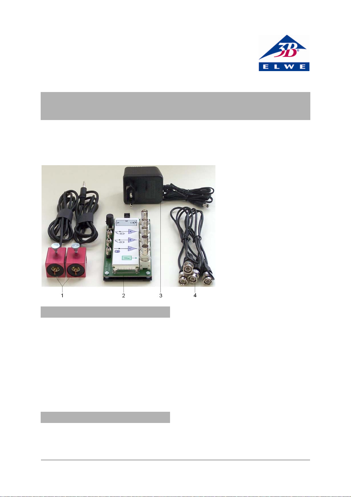
1 Dynamic
2 MEC operating electronics
3 Plug-in power supply, 230 V
(for 1012850),
not shown:
Plug-in power supply, 115 V
(for 1012851)
4 HF cable
force sensors
1. Safety instructions
The SW sensors set complies with safety regulations for electronic measuring, control and
laboratory instruments as specified in DIN EN
61010 part 1. It is designed for operation in dry
rooms which are suitable for electrical equipment.
Safe operation of the equipment can be guaranteed as long as it is used in accordance with
specifications. Safety is not, however, guaranteed if the equipment is handled incorrectly or
without due caution.
2. Description
The SW sensors equipment set is intended for
recording and analysing mechanical oscillations
with the help of an oscilloscope. Force sensors
which dynamically detect the force along their
axis are used for this.
The set with the order number 1012851 is designed for a mains voltage of 115 V (±10%)
while 1012850 is made for 230 V (±10%).
2.1 Dynamic force sensor
The dynamic force sensors can be attached to
stand rods of 10 mm in diameter or to the SW
cross bar from the SW stand equipment set
(1012849). They operate by means of the piezoelectric effect
A force applied to the hook causes the piezocrystal to charge up, whereby the charge is proportional to the applied force within certain limits. The dynamic characteristic is determined by
the finite junction resistance within the piezoelectric material and that of the impedance converter in the associated electronics.
1
Page 2
Dynamic force sensor set-up
A
The sensors are optimally designed to be mounted on
stands assembled from the SW stand equipment set
(1012849). (See instructions for pendulums listed
below.)
In addition, they can be mounted on plates or on
any rods of 10-mm diameter by means of their
knurled screw.
Caution: Dynamic force sensors must not be
subjected to mechanical overloading
• Neither sensor hook may be loaded with
more than 5N in the axial direction and 1 N
in transverse direction.
• Be especially careful with the maximum
loading force when assembling the system
or suspending loops or springs from the
hook.
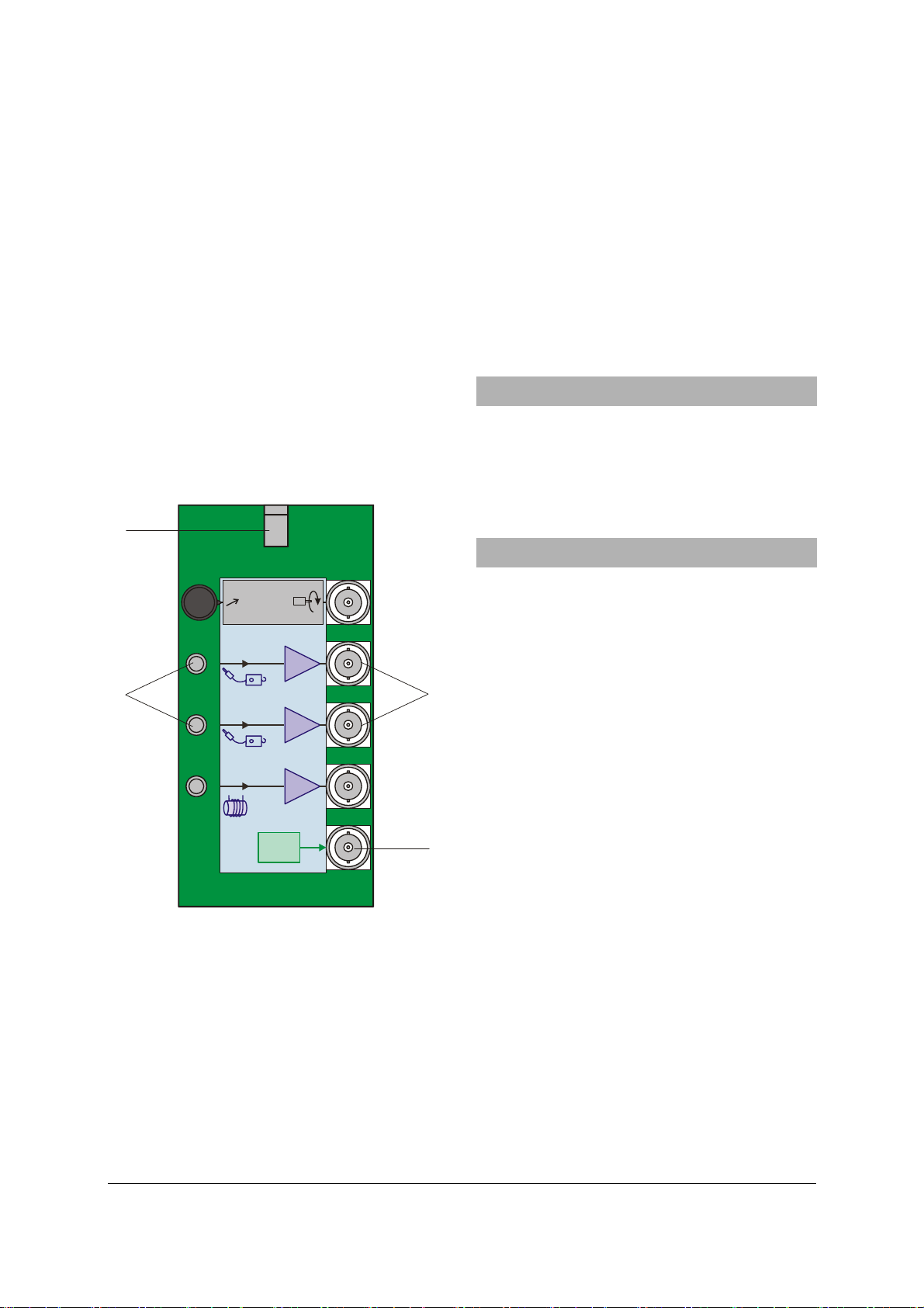
2.2 MEC electronics board
1a
12V AC
resistance. In addition, the phase difference
between the two signals can also be evaluated
and output. The other inputs on the board are
not used for this purpose.
Phase detector
A phase detector compares the waveforms for
channels A and B in the time domain to determine the difference in phase between them.
Output Δφ
ence Δφ
supplies the actual phase differ-
AB
in the form of a DC voltage between
AB
8 V (∆φ = 0°) and +8 V (∆φ = 180°).
3. Contents
2 Dynamic force sensors
2 HF cables
1 MEC electronics board
1 Plug-in power supply, 12 V AC
4. Technical data
M
f
A
1b
B
C
Δϕ
B
Fig. 1 MEC electronics board
1a Connector for plug-in mains supply
1b A and B inputs for dynamic
1c A and B outputs for dynamic
force sensors
force sensors
1c
1d
1d ΔφAB output for phase detector
Amplifier channels
Amplifier channels A and B on the MEC electronics board are used in conjunction with the
dynamic force sensors. The board converts the
signals from both sensors to make them suitable
for display in an oscilloscope or other display
instrument. The two channels have high internal
Dynamic force sensor
Maximum force
Axial plane: 5 N
Radial plane: 1 N
Lower frequency limit: 0.2 Hz
Connector: 3.5-mm jack plug
Length of cable 0.8 m
Dimensions: 52 x 37 x 26 mm approx.
Weight: 80 g approx.
Electronic board
Power supplied via plug-in mains transformer
Input sockets: 3.5-mm jack sockets
Output sockets: BNC
Amplifier A, B: Output ±8 V,
Ri = 100 MΩ
Ra = 1 kΩ
Phase detector (XOR): Output ±8 V,
Ra = 1 kΩ
Dimensions: 65 x 100 x 40 mm approx.
Plug-in power supply for 1012850
Primary side: 230 V, 50/60 Hz
Secondary side: 12 V AC; 700 mA
Plug-in power supply for 1012851
Primary side: 115 V, 50/60 Hz
Secondary side: 12 V AC; 500 mA
Only power the MEC electronics board from the
supplied 12 V AC mains transformer.
2
Page 3

5. Experiments
The following equipment is recommended for
carrying out experiments on mechanical oscillations. Use of a USB oscilloscope means that
oscilloscope software can be used to display,
evaluate and analyse oscillations on a PC.
Alternatively, any conventional oscilloscope can
also be used.
5.1 Wilberforce pendulum
1 SW Wilberforce pendulum set 1012844
1 SW stand equipment set 1012849
1 SW sensors set (@230V) 1012850
or
1 SW sensors set (@115V) 1012851
1 USB oscilloscope 2x 50 MHz 1017264
1 PC, operating system Win XP, Vista,
Win 7
5.2 Physical pendulum
1 SW physical pendulum set 1012853
1 SW stand equipment set 1012849
1 SW sensors set (@230V) 1012850
or
1 SW sensors set (@115V) 1012851
1 USB oscilloscope 2x 50 MHz 1017264
1 PC, operating system Win XP, Vista,
Win 7
5.3 String pendulum
1 SW string pendulum set 1012854
1 SW stand equipment set 1012849
1 SW sensors set (@230V) 1012850
or
1 SW sensors set (@115V) 1012851
1 USB oscilloscope 2x 50 MHz 1017264
1 PC, operating system Win XP, Vista,
Win 7
6. Disposal
• Packaging and compo-
nents should be disposed of, where necessary, at local recycling
centres.
3B Scientific GmbH ▪ Rudorffweg 8 ▪ 21031 Hamburg ▪ Germany ▪ www.3bscientific.com
Subject to technical amendments
© Copyright 2013 3B Scientific GmbH
Page 4

 Loading...