

Page 1
SCIENTIFIC
SW Set – Physical Pendulum 1012853
Instruction manual
10/13 TL/ALF
®
PHYSICS
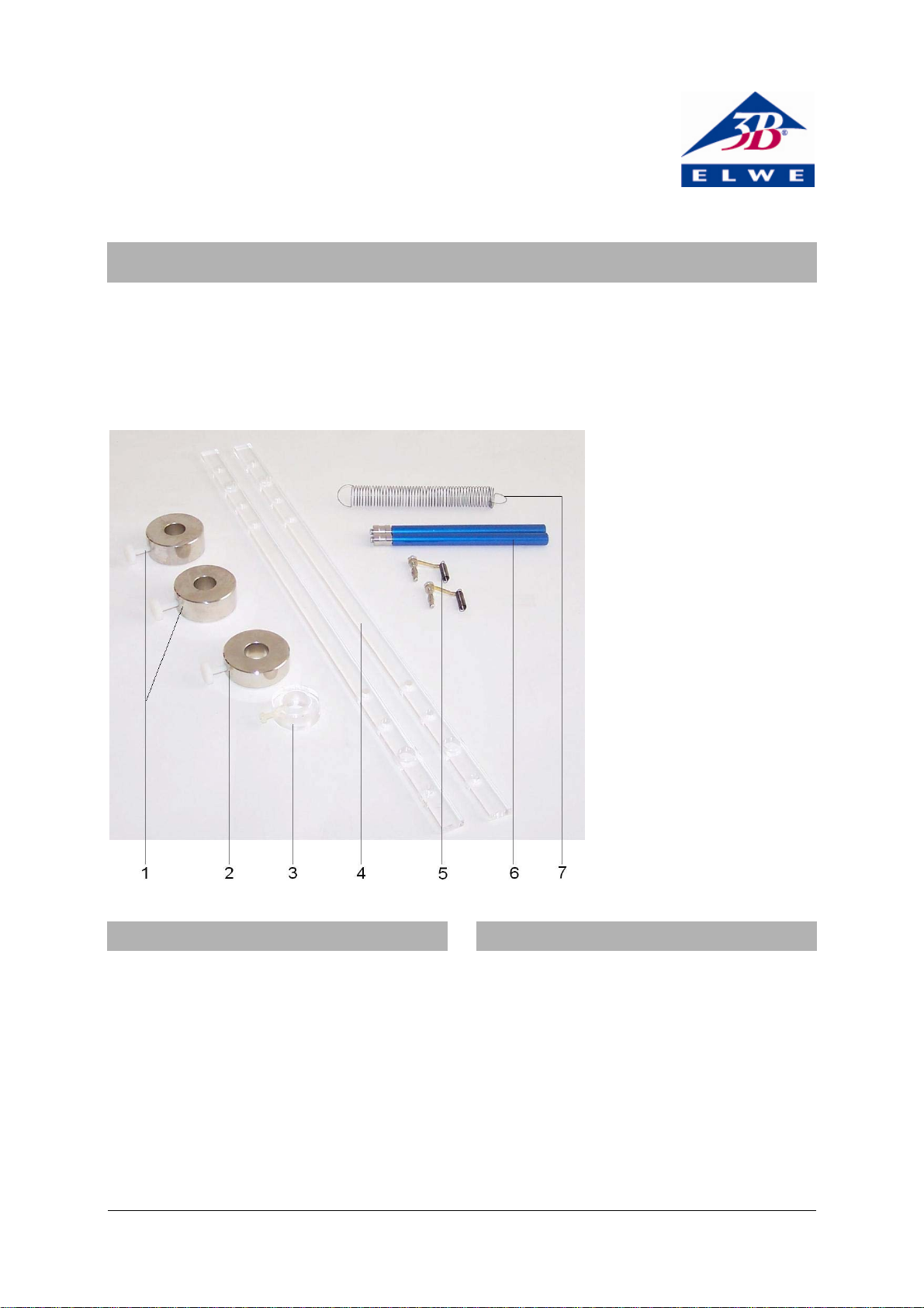
1 Weight, 200 g
2 Weight, 150 g
3 Acrylic ring
4 Pendulum rod
5 Coupling spring
6 Bearing rod
7 Tension spring
1. Description
The physical pendulum set is designed for assembly of a physical pendulum with a movable
bob, a double coupled pendulum, a reversible
(Kater) pendulum or a metronome pendulum in
a space-saving table-top experiment set-up.
It consists of pendulum rods, bearing rods and
weights for constructing the pendulums themselves, as well as additional components for
attaching them to the dynamic force sensors
from the SW sensors set in order to record and
extensively analyse the oscillations with the help
of an oscilloscope.
2. Equipment
2 Pendulum rods
2 Bearing rods
2 Weights, 200 g
1 Weight, 150 g
1 Acrylic ring
1 Tension spring
2 Coupling springs
1
Page 2
3. Technical data
Pendulum rods
• Attach a 200-g weight (pendulum bob) to the
pendulum rod with the knurled screw.
Length: 450 mm
Weight: 45 g
Separation of bearing holes : 330 mm
Material: Transparent
acrylic
Weights
Weights: 2x 200 g approx.
1x 150 g approx.
Acrylic ring: 10 g approx.
Tension springs
Spring constant: 2.5 N/m
4. Set-up of pendulums without sensors
4.1 General information
The following additional equipment is necessary
in order to carry out the experiments:
1 SW stand equipment set 1012849
1 Digital stopwatch 1002811
A stopwatch can provide sufficiently accurate
results as long as at least 10 periods are measured.
• Make sure the stand rods are firmly fitted
into the base and that all other mounting elements are also firmly fitted to the stands.
• Do not bend the pendulum rods over the
bearings (otherwise they could break).
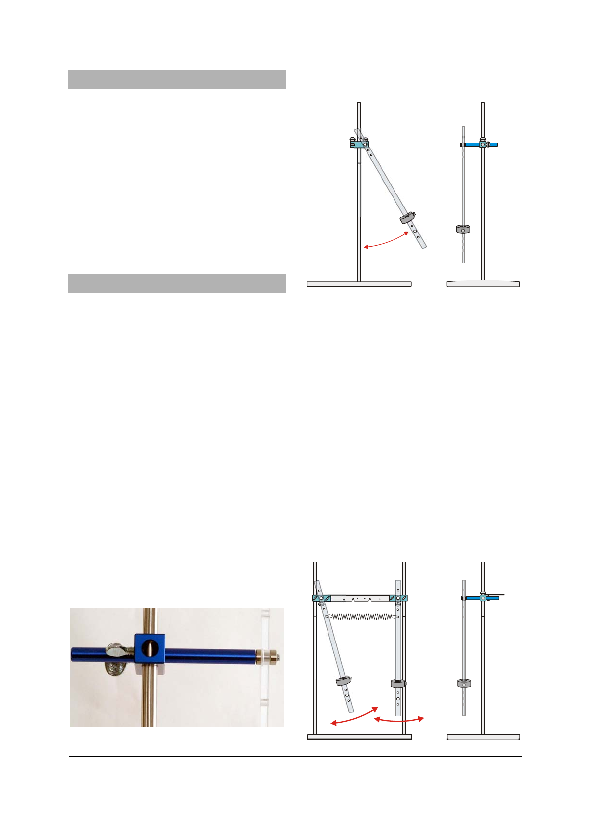
4.2 Set-up for a physical pendulum without
sensors
• Screw a stand rod with both external and
internal threads into the central threaded sockets of the base plate and extend the rod
by screwing one with external thread only
onto the end.
• Slip a double clamp onto the rod.
• Insert a bearing rod into the double clamp
Fig. 2 Set-up for physical pendulum without sensors
4.3 Set-up for a double pendulum without
sensors
• Screw the stand rods with both external and
internal threads into the outer threaded sockets of the base plate.
• Extend both rods by screwing rods with ex-
ternal thread only onto the ends of them.
• Attach double clamps near the top of both
stand rods and turn them to point inwards so
that the slots are vertical and facing one another.
• Clamp the cross bar into the slots of the two
double clamps.
• Insert bearing rods into the double clamps
and slot pendulum rods over the bearings.
• Couple the pendulum rods together with a
tension spring.
• Attach 200-g weights (pendulum bobs) to
the pendulum rods with the knurled screws.
and slot the pendulum rod over the bearing.
Fig. 1 Set-up of pendulum rods
Fig. 3 Set-up for coupled pendulum without sensors
2
Page 3

4.4 Set-up for a reversible (Kater) pendulum
• Set up the pendulum stand as described in
4.2.
• To set up a reversible pendulum, position a
200-g weight between the bearing holes and a
150-g weight at the top end of the pendulum.
Note:
• Only deflect the pendulum by small angles.
If the bearing holes are l = 330 mm apart, as
long as the pendulum is correctly adjusted, the
oscillation about either bearing should have a
period T = 1.152 s (g = 9.81 m/s²).
2
l
⋅π
4
T
=
g
Fig. 4 Set-up for reversible pendulum
4.5 Set-up for metronome pendulum
• Set up the pendulum stand as described in
4.2.
• Attach a 200-g weight at the bottom of the
pendulum rod with the knurled screw.
• Attach the acrylic ring near the top of the
pendulum.
Note: This pendulum can be used to achieve a
wide variety of periods.
By moving the large weight, the oscillating sys-
tem can be adjusted to approach an indifferent
equilibrium. Period durations are then effectively
limited only by friction at the bearings.
Fig. 5 Set-up for a metronome pendulum
5. Set-up for pendulums with sensors
5.1 General information
The following additional equipment is necessary
in order to carry out the experiments:
1 SW stand equipment set 1012849
1 SW sensors set (@230V) 1012850
or
1 SW sensors set (@115V) 1012851
1 USB oscilloscope 2x 50 MHz 1017264
1 PC, operating system Win XP, Vista, Win 7
or
1 Analog oscilloscope 2x 30 MHz 1002727
Caution: Dynamic force sensors must not be
subjected to mechanical overloading
• Neither sensor hook may be loaded with
more than 5N in the axial direction and 1 N
in transverse direction.
• Be especially careful with the maximum
loading force when assembling the system
or suspending loops or springs from the
hook.
• Make sure stand rods are firmly fitted into
the base and that all other mounting elements are also firmly fitted to the stands.
• Do not bend the pendulum rods over the
bearings (otherwise they could break).
The force sensors can be set up with high or low
pre-tensioning of the coupling springs (by attaching them to two different positions on the
cross bar). This means that the distance between pendulum rod and force sensor may differ. One position allows for high amplitudes with
long pendulum swings, whereas the other provides for low bearing friction but only short pendulum swings and therefore small amplitudes
are possible.
3
Page 4

5.2 Set-up for coupled pendulum with sensors
• Set up the pendulum stand as described in
4.3.
• Attach a force sensor to the cross bar with
the knurled screw.
• Stretch a coupling spring between the pen-
dulum rod and the force sensor.
• Clamp the bearing rod into the double clamp
in such a way that the coupling springs and
pendulum rod move in roughly the same
plane as the hook of the force sensor.
• Set up the second force sensor in the same
way.
• Couple the two pendulum rods together with
the tension spring.
• Connect the force sensors to the inputs for
channels A and B of the MEC amplifier
board.
• Connect the outputs to an oscilloscope and
start the experiment.
Fig. 8 Set-up for coupled pendulum with sensors and
USB oscilloscope
6. Disposal
• Packaging and compo-
nents should be disposed of, where necessary, at local recycling
centres.
Fig. 6 Coupling of force sensor
Fig. 7 Set up of force sensors
3B Scientific GmbH ▪ Rudorffweg 8 ▪ 21031 Hamburg ▪ Germany ▪ www.3bscientific.com
Subject to technical amendments
© Copyright 2013 3B Scientific GmbH
 Loading...