

Page 1
3B SCIENTIFIC
Supplementary Set for Stirling Engine D U8440455
Instruction manual
02/11 ALF
®
PHYSICS
1. Description
The supplementary set for the D-series Stirling engine provides accessories necessary for mounting a
displacement sensor (U11371) and a relative pressure
sensor (U11321) to the Stirling engine D (U8440450).
in order to record a pressure-volume diagram for the
Stirling engine in conjunction with the 3B NETlog™
interface (U11300-115 or U11300-230).
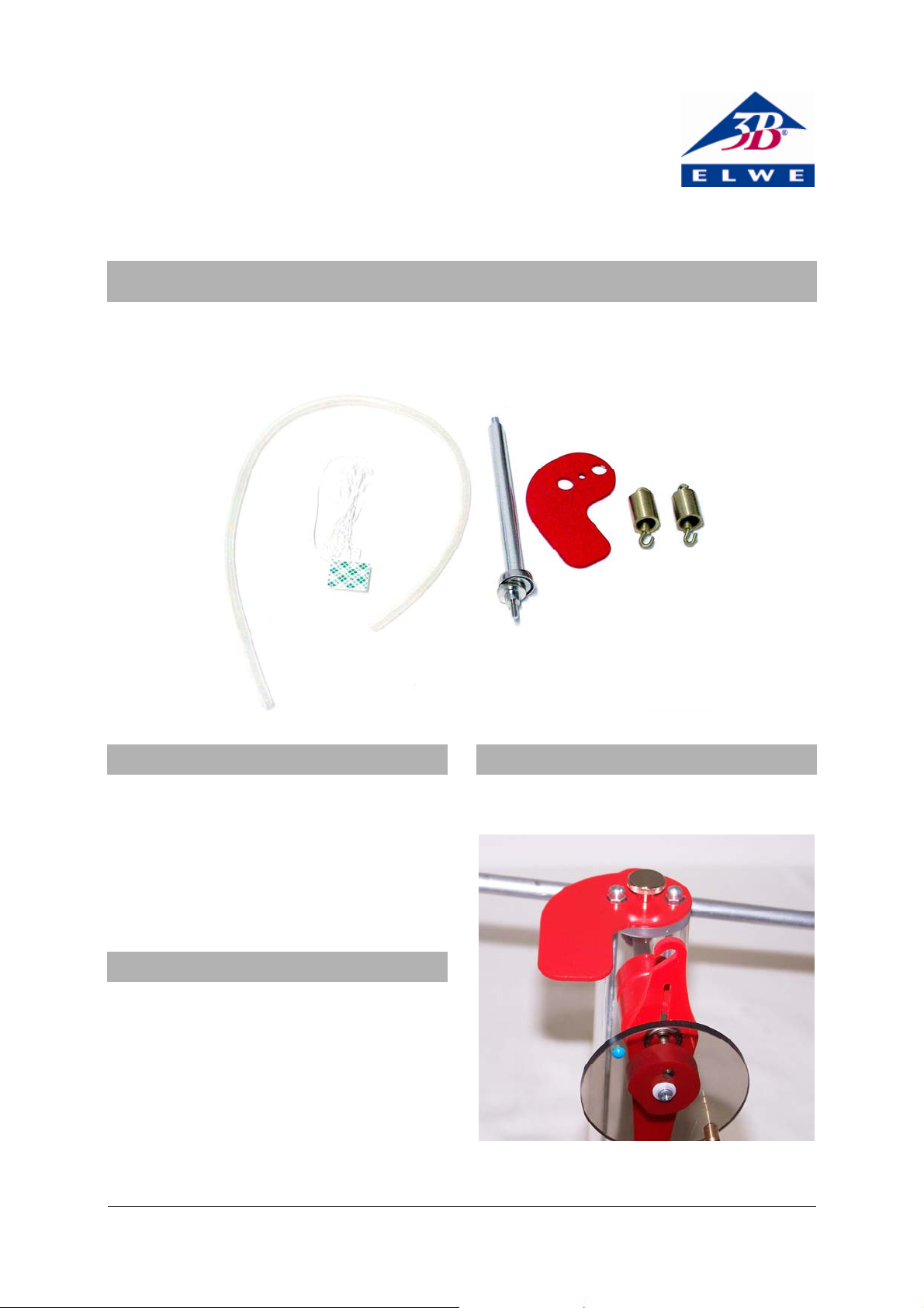
2. Contents
1 Base plate to accommodate the pressure sensor
1 Knurled screw for fastening the base plate to a
stand rod
1 Stem with magnetic base for displacement sensor
1 Silicone tubing for connecting ±100-hPa relative
pressure sensor (U11321)
1 Set of threads with suction pad
2 Weights with hook, 20 g each
3. Set-up
• Attach the base plate to the stand using the
knurled screw.
Fig. 1 Assembly on base plate
1
Page 2
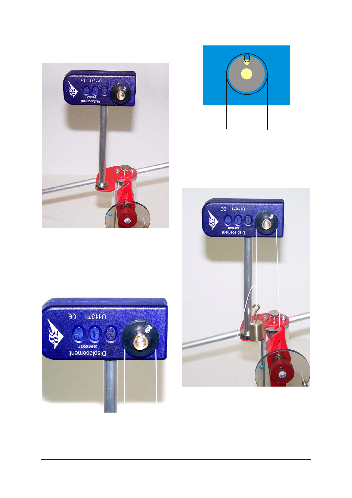
• Screw the stem with the magnetic base into the
displacement sensor and place it on the base plate.
Fig. 4 Schematic illustration of how the thread is wound
around the pulley of the displacement sensor
(U11371)
• Attach one end of the thread to the hook of the
connector rod and suspend a weight from the
other end.
Fig. 2 Assembly of displacement sensor
• Loosen the screw on the displacement sensor’s
pulley. Wind a thread once around the pulley
and lead it out of the recess placing a loop
around the screw. Use the screw to fix the thread
in place.
Fig. 3 How the thread is wound around the pulley
Fig. 5 Attaching the thread to the hook on the connector
rod
• Use the suction pad to attach a second thread to
the base plate. Thread this over the groove in
the eccentric and use the other weight as a load
on the free end.
This load ensures that the pV diagram comes out better.
2
Page 3

Fig. 6 A weight is attached to the end of the thread
Connect the relative pressure sensor (hoze nozzle
•
“+”) to the hose nozzle on the Stirling engine via
silicone tubing.
Fig. 7 Connecting the pressure sensor
• Connect the pressure sensor to analog input A of
the 3B NETlog
TM
unit and the displacement sen-
sor to analog input B.
Fig. 8 Set-up for recording a pressure-volume diagram
Elwe Didactic GmbH • Steinfelsstr. 6 • 08248 Klingenthal • Germany • www.elwedidactic.com
3B Scientific GmbH • Rudorffweg 8 • 21031 Hamburg • Germany • www.3bscientific.com
Subject to technical amendments
© Copyright 2011 3B Scientific GmbH
Page 4

 Loading...