

Page 1
3B SCIENTIFIC
Stirling-Motor transparent U10050
Bedienungsanleitung
03/08 ALF
®
PHYSICS
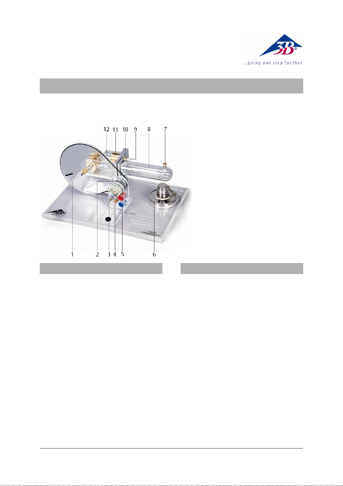
1 Schwungrad mit Markierung
(zur Bestimmung der Drehzahl
2 Motor-Generator-Einheit mit
zweistufiger Riemenscheibe
3 Schalter
4 Glühbirne
5 4-mm-Sicherheitsbuchsen
6 Spiritusbrenner
7 Temperatur-Messstutzen 1
8 Verdrängerkolben
9 Schlauchanschluss mit Kap-
pe für Druckmessungen
10 Temperatur-Messstutzen 2
11 Arbeitskolben
12 Gewindestange M3 (verbun-
den mit Arbeitskolben)
1. Sicherheitshinweise
• Brennspiritus vorsichtig in Spiritusbrenner
einfüllen, darauf achten, dass nichts verschüttet wird.
• Spiritusbrenner nie befüllen, solange der Docht
noch glimmt oder eine andere offene Flamme
in der Nähe ist.
• Spiritusflasche nach Gebrauch sofort verschlie-
ßen.
• Nicht in die offene Flamme fassen.
• Vorsicht! Flamme nur mit befestigtem Deckel
löschen.
Der Stirlingmotor erhitzt sich beim Betrieb mit
offener Flamme.
• Während und nach dem Betrieb des Stirling-
motors Verdrängungszylinder nicht berühren.
• Stirlingmotor vor dem Wegräumen abkühlen
lassen.
2. Beschreibung
Der Stirlingmotor ermöglicht die qualitative und
quantitative Untersuchung des Stirlingschen Kreisprozesses. Er kann in drei verschiedenen Modi
betrieben werden: als Wärmekraftmaschine, als
Wärmepumpe und als Kältemaschine.
Verdrängungszylinder und Verdrängerkolben bestehen aus hitzebeständigem Glas, Arbeitszylinder,
Schwungrad und Getriebeabdeckungen aus Acrylglas. Somit lassen sich jederzeit die einzelnen Bewegungsabläufe sehr gut beobachten. Die Kurbelwellen sind kugelgelagert und bestehen aus gehärtetem Stahl. Die Pleuel sind aus verschleißfestem
Kunststoff gefertigt.
Die eingebaute Motor-Generator-Einheit mit zweistufiger Riemenscheibe ermöglicht die Umwandlung der erzeugten mechanischen Energie in elektrische Energie. Mit Umschaltmöglichkeit zum Betrieb einer eingebauten Lampe sowie zum Betrieb
externer Lasten oder zur Einspeisung elektrischer
Energie zum Betrieb als Wärmepumpe oder Kältemaschine.
Durch Befestigung des im Lieferumfang enthaltenen Fadens an der Gewindestange am Arbeitskolben lässt sich dessen Hubweg messen.
1
Page 2

3. Technische Daten
Motor-Generator-Einheit: max. 12 V DC
Riemenscheibe zweistufig: 30 mm Ø, 19 mm Ø
Arbeitskolben: 25 mm Ø
Hub Arbeitskolben: 24 mm
25cmmm
Volumenänderung: 24 mm
⎛
⎜
⎝
⎞
⎟
2
⎠
3
=π⋅
12
Minimum Volumen: 32 cm³
Maximum Volumen: 44 cm³
Leistung des
Stirlingmotors: ca. 1 W
Abmessungen: ca. 300x220x160 mm³
Masse: ca. 1,65 kg
4. Schema der Funktionsweise
Der ideale Stirlingprozess läuft in 4 Takten ab (siehe Fig. 1):
1.Takt: Expansionsphase: Isotherme Zustandsänderung, die Luft expandiert bei konstanter
Temperatur
2.Takt: Isochore Zustandsänderung, die Luft kühlt
bei konstantem Volumen im Regenerator
ab
3.Takt: Kompressionsphase: Isotherme Zustandsänderung, die Luft wird isotherm komprimiert
4.Takt: Isochore Zustandsänderung, die Luft wird
im Regenerator wieder auf die Anfangstemperatur aufgeheizt
Im Stirlingmotor kann dieser Idealfall jedoch nicht
realisiert werden. Durch den Phasenversatz des
Arbeits- und Verdrängerkolbens erreicht man eine
Annäherung an diesen idealen Prozess. Dabei überlappen sich jedoch die 4 Takte. Bei der Expansion
findet schon ein Gaswechsel von heiß nach kalt
statt und bei der Kompressionsphase befindet sich
noch nicht die ganze Luft im kalten Teil des Motors.
5. Bedienung
5.1 Der Stirlingmotor als Wärmekraftmaschine
• Spiritusbrenner befüllen, in die Aussparung in
der Grundplatte einsetzen, Docht ca. 1 bis 2
mm herausdrehen und entzünden.
• Verdrängerkolben in die hinterste Position
bringen und nach kurzer Erwärmungszeit (ca. 1
bis 2 Minuten) Schwungrad durch leichtes Anschieben in Uhrzeigersinn (aus Blickrichtung
Motor-Generator-Einheit) in Bewegung versetzen (siehe Fig. 2).
• Gegebenenfalls Spannung des Treibriemens
durch Verschieben der Motor-GeneratorEinheit einstellen.
• Glühbirne durch Schalterstellung „oben“ ein-
schalten.
• Alternativ externe Last über die 4-mm-Buchsen
anschließen und in Schalterstellung „unten“
betreiben.
Drehzahl ohne Last: ca. 1000 U/min
Drehzahl mit
Generator als Last: ca. 650 U/min
Generatorspannung: ca. 6 V DC
Druckdifferenz: +250 hPa/-150 hPa
5.2 Der Stirlingmotor als Wärmepumpe oder
Kältemaschine
Zusätzlich erforderlich:
DC-Netzgerät 15 V, 1,5 A U8521121-230
oder
DC-Netzgerät 15 V, 1,5 A U8521121-115
Digital-Thermometer U11818
• Temperatursensoren in die Temperatur-
Messstutzen einsetzen und an das Digital-
Thermometer anschließen (siehe Fig. 3).
• Gleichstromquelle über die 4-mm-Buchsen
anschließen.
• Max. 12 V einstellen und Stirlingmotor in
Schalterstellung „unten“ betreiben.
• Temperaturzunahme bzw. –abnahme beo-
bachten.
Im Betriebsmodus Kältemaschine dreht das
Schwungrad im Uhrzeigersinn (aus Blickrichtung
Motor-Generator-Einheit), im Betriebsmodus Wärmepumpe entgegen dem Uhrzeigersinn.
• Zum Wechsel der Betriebsmodi Anschlusskabel
umpolen.
Druckdifferenz: +250 hPa/-150 hPa
Motorspannung: 9 V
Drehzahl: 600 U/min
Temperaturdifferenz (bezogen auf 21° C):
Kältemaschine: -4 K (Reservoir: +6 K)
Wärmepumpe: +13 K (Reservoir: -1 K)
5.3 Aufnahme der Betriebsdruckwerte im Ar-
beitskolben
Zusätzlich erforderlich:
3B NETlog
3B NETlab
TM
U11300
TM
U11310
Relativ-Drucksensor ±1000 hPa U11322
• Druckverbindungen zwischen „positiver“
Schlauchwelle der Sensorbox und der
Schlauchanschlussöffnung am Arbeitszylinder
herstellen (siehe Fig. 4).
• Drucksensor mit dem 3B NETlog
• Software starten und Messung durchführen.
TM
verbinden.
2
Page 3
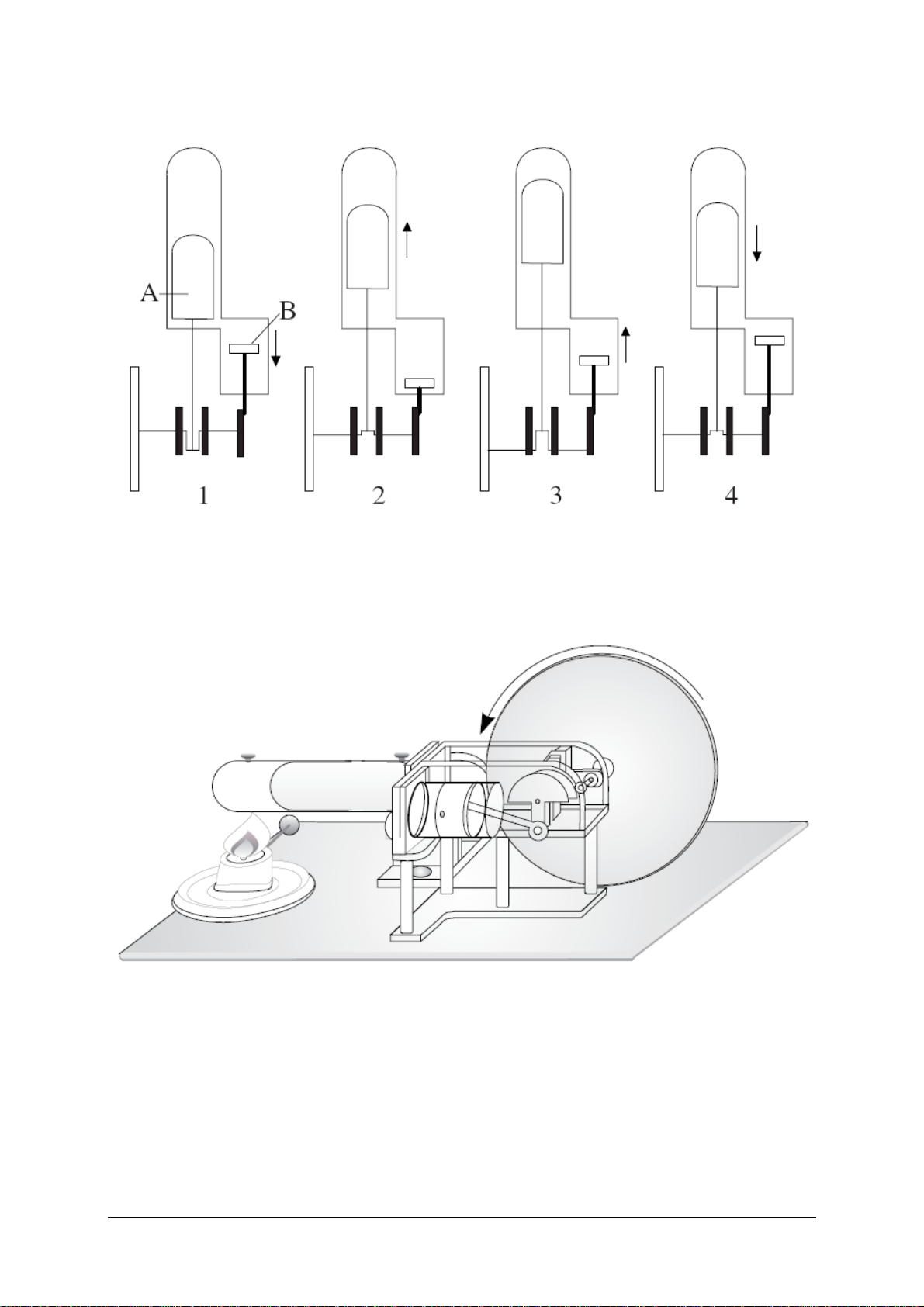
Fig. 1 Schema der Funktionsweise (A: Verdrängerkolben, B: Arbeitskolben)
Fig.2 Der Stirlingmotor als Wärmekraftmaschine
3
Page 4

Fig. 3 Der Stirlingmotor als Wärmepumpe oder Kältemaschine
Fig. 4 Aufnahme der Betriebsdruckwerte im Arbeitskolben
3B Scientific GmbH • Rudorffweg 8 • 21031 Hamburg • Deutschland • www.3bscientific.com
Technische Änderungen vorbehalten
© Copyright 2008 3B Scientific GmbH
Page 5
3B SCIENTIFIC
Stirling Engine, Transparent U10050
Instruction Sheet
03/08 ALF
1. Safety instructions
®
PHYSICS
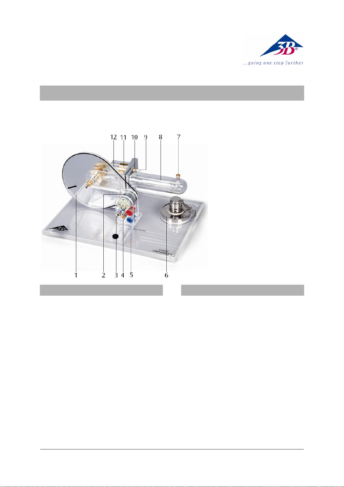
1 Flywheel with marking for
speed determination
2 Motor-generator unit with
2-stage pulley
3 Switch
4 Bulb
5 4-mm safety plugs
6 Alcohol burner
7 Temperature measure-
ment connector 1
8 Displacement piston
9 Capped hose connection
for pressure measure-
ments
10 Temperature measure-
ment connector 2
11 Working piston
12 Threaded rod M3 (con-
nected with the working
piston)
2. Description
• Pour the fuel alcohol carefully into the alco-
holburner, making sure that none of it is spilt.
• Never fill the alcoholburner as long the wick is
still smoldering or another open flame is in
close proximity.
• Immediately close the fuel container after use.
• Keep away from the open flame.
• Caution! Only extinguish the flame by fitting
the cover provided for this purpose.
The Stirling engine becomes hot when it is operated with an open flame.
• Do not touch the displacement cylinder during
or immediately after operation of the Stirling
motor.
• Allow the Stirling engine to cool before putting
it away.
The Stirling engine can be used for qualitative and
quantitative investigations of the Stirling cycle.and
can be operated in three different modes: heat
engine, heat pump and refrigerator.
The displacement cylinder and piston are made of
heat-resistant glass; the working cylinder, flywheel
and transmission covers are made of acrylic glass.
This allows a very clear observation of the individual motion sequences at all times. The crankshafts are equipped with ball bearings and made of
hardened steel. The connecting rods consist of
wear-resistant plastic. The integrated motorgenerator unit with a 2-stage pulley allows the
generated mechanical energy to be converted into
electrical energy. A switchover mechanism permits
operation of an integrated lamp or external loads,
as well as a feeding of electrical energy in order to
simulate a heat pump or refrigerator.
By attaching the thin cord supplied with the apparatus to the threaded rod on the work piston, the
stroke length can be measured.
1
Page 6

3. Technical data
Motor-generator unit: max. 12 V DC
2-stage pulley: 30 mm dia., 19 mm dia.
Working piston: 25 mm dia.
Path of working piston: 24 mm
25cmmm
Volumetric change: 24 mm
⎛
⎜
⎝
⎞
⎟
2
⎠
3
=π⋅
12
Minimum volume: 32 cm³
Maximum volume: 44 cm³
Power of the
Stirling motor: 1 W approx.
Dimensions: 300x220x160 mm³ ap-
prox.
Weight: 1.65 kg approx.
4. Functioning principle
An ideal Stirling cycle has 4 phases (refer to Fig. 1):
Phase 1: Isothermal change of state, during which
the air expands at constant temperature.
Phase 2: Isochoric change of state, during which
the air cools at constant volume in the regenerator.
Phase 3: Isothermal change of state, during which
the air is compressed at constant temperature.
Phase 4: Isochoric change of state, during which
the air in the regenerator is heated back to
its initial temperature.
However, the Stirling motor is not capable of
achieving this ideal behaviour. The phase shifts
between the working piston and displacement
piston only allow an approximation of the ideal
process, the 4 different phases exhibiting a certain
degree of overlap: Already during expansion, the
gas temperature changes from hot to cold, and
when compression begins, some of the air has not
yet reached the cold part of the motor.
5. Operation
5.1 The Stirling Engine as a heat engine
• Fill the methylated-spirit burner, place it in the
recess in the base-plate, twist out about 1-2
mm of the wick, and ignite it.
• Move the displacer piston to its farthest-back
position, and after a short heating-up time
(about 1-2 minutes) push the flywheel gently in
the clockwise direction (as seen from the motor-generator unit) to set it turning (see Fig. 2).
• If necessary, adjust the tension of the drive belt
by moving the motor-generator unit.
• Turn on the filament lamp by moving the
switch to the “up” position.
• Alternatively, connect an external load through
the 4 mm sockets and drive it by moving the
switch to the “down” position.
Speed without a load: 1000 rpm approx.
Speed with a generator
as the load: 650 rpm approx.
Generator voltage: 6 V DC approx.
Pressure difference: +250 hPa / -150 hPa
5.2 The Stirling motor as a heat pump or refrig-
erator
Additional instruments needed:
DC Power supply 15 V, 1.5 A U8521121-115
or
DC Power supply 15 V, 1.5 A U8521121-115
Digital thermometer U11818
• Insert temperature sensors into the thermome-
ter sockets and connect them to a measuring
instrument (see fig. 3).
• Connect a DC voltage source through the 4 mm
sockets.
• Adjust the voltage (maximum 12 V) and oper-
ate the Stirling engine with the switch in the
“down” position.
• Observe the increase or reduction in tempera-
ture.
In the refrigerator mode of operation, the flywheeI
rotates in the clockwise direction (as seen from the
motor-generator unit), whereas in the heat pump
mode it rotates in the anticlockwise direction.
• To switch between the two modes of operation,
reverse the polarity of the connections.
Pressure difference: +250 hPa / -150 hPa
Motor voltage: 9 V
Speed: 600 rpm
Temperature difference (with respect to 21° C):
Refrigerator: -4 K (reservoir: +6 K)
Heat pump: +13 K (reservoir: -1 K)
5.3 Recording the operating pressure on the
work piston
Additional instruments needed:
3B NETlog
3B NETlab
TM
U11300
TM
U11310
Relative pressure sensor, ±1000 hPa U11322
• Connect a pressure hoses between the “posi-
tive” hose connector of the sensor box and the
hose connector on the work cylinder (see fig.
4).
• Connect the pressure sensor to the 3B NETlog
• Start the program software and carry out the
TM
.
measurements.
2
Page 7
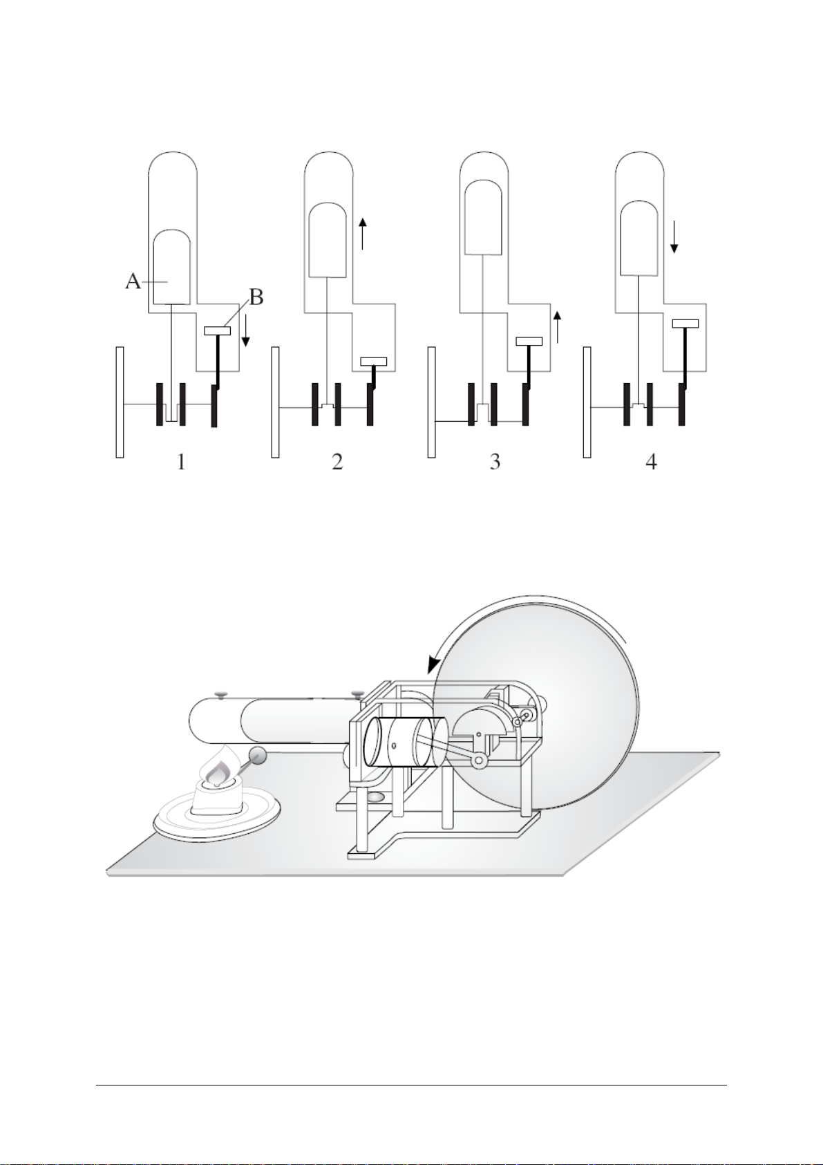
Fig. 1 Functioning principle (A: Displacement piston, B: Working piston)
Fig.2 The Stirling motor as a heat engine
3
Page 8
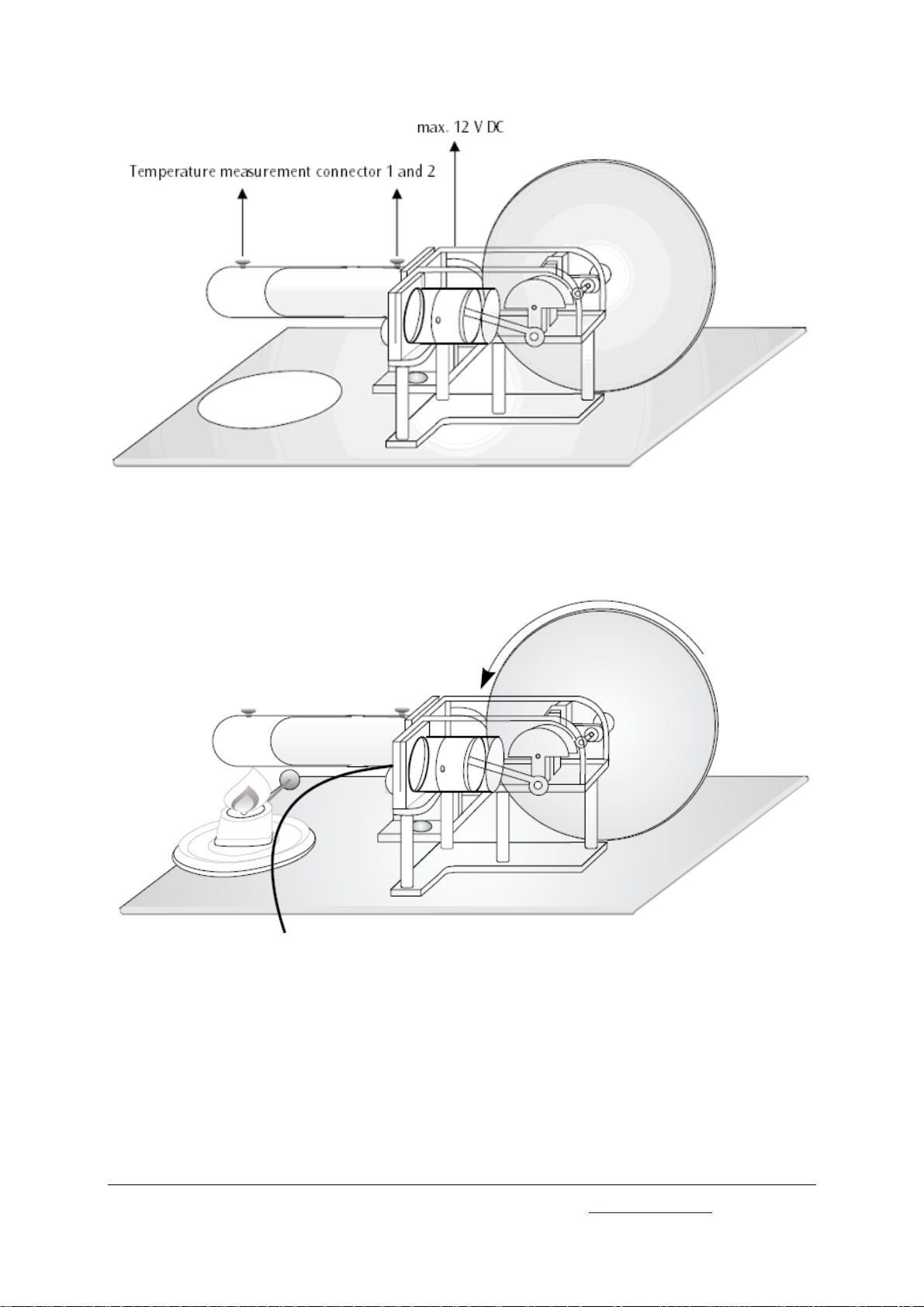
Fig. 3 The Stirling motor as a heat pump or refrigerator
Fig. 4 Recording the operating pressure on the work piston
3B Scientific GmbH • Rudorffweg 8 • 21031 Hamburg • Germany • www.3bscientific.com
Subject to technical amendments
© Copyright 2008 3B Scientific GmbH
Page 9

3B SCIENTIFIC
Moteur Stirling, transparent U10050
Instructions d'utilisation
03/08 ALF
®
PHYSICS
1 Roue volante avec repère
pour déterminer la vitesse
2 Unité moteur – générateur
avec poulie à deux étages
3 Interrupteurs
4 Ampoule
5 Douilles de sécurité de 4
mm
6 Brûleur à alcool
7 Support de mesure de
température 1
8 Piston déplaceur
9 Raccord de tuyau avec
chape pour mesures de
pression
10 Support de mesure de
température 2
11 Piston de travail
12 Tige filetée M3 (reliée au
piston de travail)
1. Consignes de sécurité
• Remplir avec précaution l’alcool dénaturé dans
le brûleur ; veiller à ne pas en renverser.
• Ne jamais remplir le brûleur à alcool tant que
la mèche répand encore une faible lueur ou
qu’une autre flamme directe est allumée à proximité.
• Après son emploi, refermer immédiatement la
bouteille d’alcool.
• Ne pas mettre la main dans la flamme.
• Prudence ! Eteindre la flamme uniquement
lorsque le couvercle est fixé.
Le moteur Stirling se réchauffe en cas de fonctionnement avec une flamme nue.
• Pendant et après l’exploitation du moteur
Sterling, ne pas toucher le cylindre refouleur.
• Avant de le ranger, laissez refroidir le moteur
Stirling.
2. Description
Le moteur Stirling permet l'étude qualitative et
quantitative du cycle de Stirling. Il peut être exploité en trois modes différents : comme moteur thermique, comme thermopompe et comme machine
frigorifique.
Le cylindre et le piston refouleurs sont constitués
en verre thermorésistant, le cylindre de travail, la
roue volante et les protections de l’engrenage en
verre acrylique. Ainsi les différentes phases des
mouvements peuvent-elles à tout moment être très
bien observées. Les vilebrequins en acier durci sont
montés sur billes. Les bielles sont en plastique
inusable.
L’unité intégrée du moteur – générateur avec poulie à deux étages permet de transformer l’énergie
mécanique générée en énergie électrique. Avec
possibilité de commutation pour exploiter une
lampe intégrée ainsi que pour appliquer des charges externes ou alimenter l’énergie électrique pour
1
Page 10

l’emploi comme pompe thermique ou machine
frigorifique.
Mesurez la course du piston de travail en fixant le
fil fourni à la tige filetée du piston.
3. Caractéristiques techniques
Unité moteur–générateur : max. 12 V CC
Poulie à deux étages : Ø 30 mm, Ø 19 mm
Piston de travail : Ø 25 mm
Course piston de travail : 24 mm
Modification de volume :
25cmmm
24 mm
⎛
⎜
⎝
⎞
⎟
2
⎠
3
=π⋅
12
Volume minimum : 32 cm³
Volume maximum : 44 cm³
Puissance du moteur Stirling : env. 1 W
Dimensions : env. 300x220x160 mm³
Masse : env. 1,65 kg
4. Schéma du principe de fonctionnement
Le processus Stirling idéal comprend 4 phases (voir
fig. 1) :
1ère phase : Phase d’expansion : modification
d’état isothermique, l’air se détend à
température constante
2e phase : Modification d’état isochore, l’air
refroidit à volume constant dans le
régénérateur
3e phase : Phase de compression : modification
d’état isothermique, l’air est comprime isothermiquement
4e phase : Modification d’état isochore, l’air est
de nou veau réchauffé dans le régénérateur à la température initiale
Ce cas idéal ne peut cependant pas être réalisé
dans le moteur Stirling. Le décalage de phase des
pistons de travail et refouleur permet de
s’approcher du processus idéal. Mais les quatre
phases se chevauchent. Au cours de l’expansion, on
observe déjà un échange gazeux de chaud à froid
et, lors de la compression, la totalité de l’air ne se
trouve pas encore dans la partie froide du moteur.
5. Manipulation
5.1 Le moteur Stirling comme moteur thermique
• Remplissez le brûleur à alcool, placez-le dans
l'évidemment de la plaque d'assise, dégagez la
mèche sur environ 1 à 2 mm, puis allumez
cette dernière.
• Placez le piston de refoulement en butée ar-
rière et, après un bref temps de réchauffement
(environ 1 à 2 minutes), mettez la roue volante
en mouvement en la poussant légèrement
dans le sens des aiguilles d'une montre (vu de
l'unité du générateur à moteur) (voir fig. 2).
• Le cas échéant, réglez la tension de la courroie
d'entraînement en déplaçant l'unité du générateur à moteur.
• Allumez l'ampoule en réglant l'interrupteur en
position supérieure.
• Comme variante, branchez une charge externe
via la borne de 4 mm et réglez l'interrupteur
en position inférieure.
Vitesse sans charge : env. 1 000 t/min
Vitesse avec générateur
comme charge : env. 600 t/min
Tension du générateur : env. 6 V CC
Pression différentielle : +250 hPa/-150 hPa
5.2 Le moteur Stirling comme thermopompe ou
machine frigorifique
Autre(s) équipement(s) requis :
Alimentation CC 15 V, 1,5 A U8521121-115
ou
Alimentation CC 15 V, 1,5 A U8521121-115
Thermomètre numérique U11818
• Placez les sondes de température dans les
tubulures de mesure et branchez-les à un ins-
trument de mesure (voir fig. 3).
• Branchez la source de courant continu via les
bornes de 4 mm.
• Réglez max. 12 V et activez le moteur Stirling
en réglant l'interrupteur en position inférieure.
• Observez l'augmentation / réduction de tem-
pérature.
Lorsque le moteur fait office de machine frigorifi-
que, la roue volante tourne dans le sens des aiguilles d'une montre (vu de l'unité du générateur à
moteur), s'il fonctionne comme une pompe thermique, la roue tourne dans le sens inverse des
aiguilles d'une montre.
• Pour changer de mode, inversez la polarité des
câbles de connexion.
Pression différentielle : +250 hPa/-150 hPa
Tension de moteur : 9 V
Vitesse de rotation : 600 t/min
Ecart de température (rel. à 21° C)
Machine frigorifique : -4 K (réservoir : +6 K)
Thermopompe : +13 K (réservoir : -1 K)
5.3 Enregistrement des pressions de service
dans le piston de travail
Autre(s) équipement(s) requis :
3B NETlog
3B NETlab
TM
U11300
TM
U11310
Capteur de pression relative ±1000 hPa U11322
2
Page 11

• Établissez les raccords de pression entre l'axe
de tuyau « positif » de la boîte à capteur et
l'orifice de raccord de tuyau sur le vérin de travail (voir fig. 4).
• Reliez le capteur de pression au 3B NETlog
• Démarrez le logiciel et effectuez la mesure.
TM
.
Fig. 1 Schéma du principe de fonctionnement (A: Piston déplaceur, B: Piston de travail)
Fig.2 Le moteur Stirling comme moteur thermi-que
3
Page 12

Fig. 3 Le moteur Stirling comme thermopompe ou machine frigorifique
Fig. 4 Enregistrement des pressions de service dans le piston de travail
3B Scientific GmbH • Rudorffweg 8 • 21031 Hamburg • Allemagne • www.3bscientific.com
Sous réserve de modifications techniques
© Copyright 2008 3B Scientific GmbH
Page 13

3B SCIENTIFIC
Motore Stirling, trasparente U10050
Istruzioni per l'uso
03/08 ALF
®
PHYSICS
1 Volano con marcatura per
determinare il numero di
giri
2 Unità motore-generatore
con puleggia a due stadi
3 Interruttore
4 Lampadina
5 Jack di sicurezza da 4 mm
6 Bruciatore ad alcol
7 Prese di misura della
temperatura 1
8 Pistone di compressione
9 Attacco del tubo con tappo
per la misurazione della
pressione
10 Prese di misura della
temperatura 2
11 Pistone di lavoro
12 Asta filettata M3 (collegata
al pistone di lavoro)
1. Norme di sicurezza
• Riempire con attenzione il bruciatore ad alcol
con alcol da ardere, in modo tale che non
fuoriesca.
• Non riempire il bruciatore ad alcol se lo
stoppino sta ancora bruciando o se nelle
vicinanze è presente un’altra fiamma aperta.
• Dopo l’uso chiudere immediatamente il
flacone di alcol.
• Non avvicinare le mani alla fiamma aperta.
• Attenzione! Spegnere la fiamma solo con il
coperchio fissato.
Il motore Stirling si riscalda durante il
funzionamento con fiamma aperta.
• Non toccare il cilindro di compressione
durante e al termine del funzionamento del
motore Stirling.
• Lasciare raffreddare il motore prima di
rimuoverlo.
2. Descrizione
Il motore Stirling permette l’analisi qualitativa e
quantitativa del ciclo di Stirling. Può essere
utilizzato in tre modalità diverse: motore termico,
pompa di calore o macchina frigorifera.
Il cilindro e il pistone di compressione sono
realizzati in vetro resistente alle alte temperature;
il cilindro di lavoro, il volano e le protezioni del
cambio sono invece in vetro acrilico. In questo
modo è possibile osservare molto bene i singoli
movimenti in qualsiasi momento. Gli alberi a
gomiti hanno cuscinetti a sfera e sono realizzati in
acciaio temprato. Le bielle sono di
plasticaresistente all’usura.
L’unità motore-generatore incorporata, dotata di
puleggia a due stadi consente di trasformare
l’energia meccanica generata in energia elettrica.
Con possibilità di commutazione per l’azionamento
di una lampada incorporata o di carichi esterni,
oppure per alimentare energia elettrica per il
1
Page 14

funzionamento in qualità di pompa di calore o
macchina frigorifera.
Fissando il filo in dotazione all'asta filettata del
pistone di lavoro, è possibile misurarne la corsa.
3. Dati tecnici
Unità motore-generatore: max. 12 V CC
Puleggia a due stadi: 30 mm Ø, 19 mm Ø
Pistone di lavoro: 25 mm Ø
Corsa pistone di lavoro: 24 mm
Variazione del volume:
25cmmm
24 mm
⎛
⎜
⎝
⎞
⎟
2
⎠
3
=π⋅
12
Volume minimo: 32 cm³
Volume massimo: 44 cm³
Potenza del motore Stirling: ca. 1 W
Dimensioni: ca. 300x220x160 mm³
Peso: ca. 1,65 kg
4. Schema di funzionamento
Il ciclo Stirling ideale avviene in 4 fasi:
1a fase: fase di espansione: cambiamento di stato
isotermico, l’aria si espande a temperatura
costante
2a fase: cambiamento di stato isocorico, l’aria si
raf fredda a volume costante nel
rigeneratore
3a fase: fase di compressione: cambiamento di
stato isotermico, l’aria viene compressa in
modo isotermico
4a fase: cambiamento di stato isocorico, l’aria
viene di nuovo riscaldata alla temperatura
origina ria nel rigeneratore
Tuttavia questa situazione ideale non può essere
realizzata nel motore Stirling. Spostando le fasi del
pistone di lavoro e del pistone di compressione è
possibile avvicinarsi al ciclo ideale. Tuttavia così le
4 fasi si sovrappongono. Durante l’espansione la
temperatura del gas passa già da calda a fredda e
durante la fase di compressione tutta l’aria non si
trova ancora nella parte fredda del motore.
5. Utilizzo
5.1 Il motore Stirling come motore termico
• Riempire il bruciatore ad alcool, inserirlo
nell’incavo della piastra di base, estrarre
svitando lo stoppino di circa 1-2 mm e
accenderlo.
• Portare i pistoni di compressione nella
posizioni più arretrata e dopo un breve
periodo di riscaldamento (da 1 a 2 minuti
circa) mettere in movimento il volano con una
leggera pressione in senso orario (sguardo
rivolto verso l'unità motore-generatore) (vedere
fig. 2).
• Se necessario, impostare la tensione della
cinghia di trasmissione spostando l'unità
motore-generatore.
• Accendere la lampadina spostando
l'interruttore nella posizione “sopra”.
• In alternativa collegare il carico esterno
tramite le prese da 4 mm e mettere in
funzione con l’interruttore in posizione "sotto".
Numero di giri senza carico: ca. 1000 giri/min
Numero di giri con generatore come carico:
ca. 650 giri/min
Tensione generatore: ca. 6 V CC
Scarto di pressione: +250 hPa/-150 hPa
5.2 Il motore Stirling come pompa di calore o
macchina frigorifera
Dotazione supplementare necessaria:
Alimentatore DC 15 V, 1,5 A U8521121-115
oppure
Alimentatore DC 15 V, 1,5 A U8521121-115
Termometro digitale U11818
• Inserire i sensori di temperatura nelle prese di
misura della temperatura e collegarli ad un
misuratore (vedere fig. 3).
• Collegare la sorgente di corrente continua
tramite le prese da 4 mm.
• Impostare al massimo 12 V e azionare il
motore di Stirling con l'interruttore in
posizione "sotto".
• Osservare l’aumento o la diminuzione di
temperatura.
In modalità di funzionamento macchina frigorifera
il volano ruota in senso orario (sguardo rivolto
verso l'unità motore-generatore), in modalità
pompa di calore in senso antiorario.
• Per cambiare la modalità di funzionamento
invertire la polarità dei cavi di collegamento.
Scarto di pressione: +250 hPa/-150 hPa
Tensione motore: 9 V
Numero di giri: 600 giri/min
Differenza di temperatura (riferita a 21° C):
Macchina frigorifera: -4 K (serbatoio: +6 K)
Pompa di calore: +13 K (serbatoio: -1 K)
5.3 Registrazione dei valori della pressione di
esercizio nel pistone di lavoro
Dotazione supplementare necessaria:
3B NETlog
3B NETlab
TM
U11300
TM
U11310
Sensore di pressione relativa ±1000 hPa U11322
2
Page 15

• Creare i collegamenti a pressione tra albero
flessibile “positivo” della scatola del sensore e
l’apertura di attacco del tubo nel cilindro di
lavoro (vedere fig. 4).
• Collegare il sensore di pressione con il 3B
• Avviare il software e procedere con la
NETlog
TM
.
misurazione.
Fig. 1 Schema di funzionamento (A: Pistone di compressione, B: Pistone di lavoro)
Fig.2 Il motore Stirling come motore termico
3
Page 16

Fig. 3 Il motore Stirling come pompa di calore o macchina frigorifera
Fig. 4 Registrazione dei valori della pressione di esercizio nel pistone di lavoro
3B Scientific GmbH • Rudorffweg 8 • 21031 Amburgo • Germania • www.3bscientific.com
Con riserva di modifiche tecniche
© Copyright 2008 3B Scientific GmbH
Page 17

3B SCIENTIFIC
Motor Stirling, transparente U10050
Instrucciones de uso
03/08 ALF
®
PHYSICS
1 Volante con marcas para la
determinación de las
revoluciones
2 Unidad motor-generador
con polea de dos escalones
3 Interruptor
4 Bombilla eléctrica
5 Clavijeros de seguridad de
4 mm
6 Mechero de alcohol
7 Conexión para medición
de temperatura 1
8 Pistón desplazador
9 Conexión de la manguera
con tapa para mediciones
de presión
10 Conexión para medición
de temperatura 2
11 Pistón principal
12 Vástago roscado M3
(conectado al émbolo de
trabajo)
1. Advertencias de seguridad
• Rellene con cuidado el mechero de alcohol con
el líquido inflamable y tenga cuidado de que
no se derrame.
• No llenar el mechero de alcohol mientras la
mecha arda o se encuentre cerca de otra flama
• Cierre la botella de alcohol inmediatamente
después de usarla
• No acerque las manos a la llama.
• Atención: Apague la llama únicamente
utilizando una tapa fija.
El motor de Stirling se recaliente al trabajar con
una llama abierta.
• No toque el cilindro de desplazamiento de el
motor Stirling esté funcionando o tras su
funcionamiento.
• El motor de Stirling se deja enfriar antes de ser
guardado.
El motor de Stirling hace posible los estudios cuantitativo y cualitativo del ciclo termodinámico de
Stirling. El motor Stirling puede operar en tres modos diferentes: como motor térmico, bomba térmica y máquina frigorífica.
El cilindro de desplazamiento y el pistón desplazador son de vidrio resistente al calor; el cilindro de
trabajo, el volante y la cubierta del engranaje son
de vidrio acrílico. De esta manera, en cualquier
momento, se pueden observar claramente los procesos dinámicos individuales. Los cigüeñales están
montados sobre rodamiento de bolas y son de acero templado. Las bielas están fabricadas en plástico
resistente al desgaste.
La unidad motor-generador incorporada, con polea
de dos escalones, permite la transformación de la
energía mecánica generada en energía eléctrica. Es
posible la conmutación para el servicio de una
2. Descripción
1
Page 18

lámpara incorporada o para operación de cargas
externas, así como para alimentación de energía
eléctrica durante el servicio como bomba térmica o
máquina refrigerante.
5.1 El motor de Stirling como máquina térmica
• Se llena el mechero de alcohol, se coloca en la
El hilo que se encuentra en el volumen de
suminstro se fija en la varilla soporte adaptada al
émbolo de trabajo para poder medir la carrera del
• Se lleva el émbolo de desplazmiento a la
mismo.
3. Datos técnicos
Unidad motor-generador: max. 12 V DC
Polea de dos niveles: 30 mm Ø, 19 mm Ø
• Si es necesario se ajusta la tensión de la correa
Pistón principal: 25 mm Ø
Émbolo de pistón principal: 24 mm
• Se conecta la lámpara incandescente en la po-
Variación de
25cmmm
volumen: 24 mm
⎛
⎜
⎝
⎞
⎟
2
⎠
3
=π⋅
12
Volumen mínimo: 32 cm³
Volumen máximo: 44 cm³
Potencia del motor Stirling: aprox. 1 W
Dimensiones: aprox. 300x220x160
mm³
Peso: aprox. 1,65 kg
• Alternativamente se conecta una carga externa
Revoluciones sin carga: aprox. 1000 n/min
Revoluciones con la
carga del generador: aprox. 650 n/min
Tensión del generador: aprox. 6 V DC
Diferencia de presión: +250 hPa/-150 hPa
5.2 El motor de Stirling como bomba de calor o
4. Esquema de funcionamiento
El proceso de Stirling ideal se compone de 4 pasos
(ver fig. 1):
1er paso: Fase de expansión: Cambio de estado
isotérmico, el aire se expande por una
temperatura constante.
2º paso: Cambio de estado isocórico, el aire se
enfría con un volumen constante en el
Se require adicionalmente:
Fuente de alimentación de CC 15 V, 1,5 A
U8521121-115
o
Fuente de alimentación de CC 15 V, 1,5 A
U8521121-115
Termómetro digital U11818
• Los sensores de temperatura se colocan en los
regenerador.
3er paso: Fase de compresión: cambio de estado
isotérmico, el aire se comprime
isotérmicamente.
4º paso: Cambio de estado isocórico, el aire
vuelve a subir a la temperatura inicial
• Se connecta la fuente de corriente continua
• Ajuste una tensión max de 12 V y trabaje con el
en el regenerador.
Este proceso ideal no puede llevarse a cabo con el
motor Stirling. Pasando por estas fases, con el
• Observe el aumento resp. la disminucion de la
pistón principal y el pistón desplazador, se
consigue una aproximación a este proceso ideal.
Sin embargo las cuatro fases se superponen. En la
expansión, se produce un cambio de gases de calor
a frío, y en la fase de compresión no todo el aire
está ya en la parte fría del motor.
En el modo de trabajo como máquina frigorífica la
rueda volante se mueve en sentido de las
manecillas del reloj (desde la dirección de
observación de la unidad motor–generador), en el
modo de trabajo como bomba de calor se mueve
en contra del sentido de las manecillas del reloj.
• Para cambiar los modos de trabajo se invierte
Diferencia de presión: +250 hPa/-150 hPa
5. Manejo
escotadura de la placa base; se saca la mecha
de 1 a 2 mm aprox. y se enciende.
posición más posterior y después de un corto
tiempo de calentamiento (aprox. de 1 a 2
minutos) se pone en rotación la rueda volante
dándole un empujón suave en dirección de las
agujas del reloj (en dirección de observación
de la unidad motor–generador) (ver fig. 2).
de transmisión de la unidad motor–generador.
sición de conmutación “ arriba“.
por medio de los casquillos de 4 mm y se
trabaja en la posición de conmutador “abajo“.
como máquina frigorófica
manguitos de medida de temperatura y se
conectan con un aparato de medida de
temperatura (ver fig. 3).
por medio de los casquilos de 4 mm.
motor de Stirling en la posición de conmutador
“abajo “.
temperatura.
la polaridad del cable de conexión.
2
Page 19

Tensión del motor: 9 V
Revoluciones: 600 n/min
Diferencia de temperatura (a partir de 21° C):
Máquina frigorífica: -4 K (depósito: +6 K)
Bomba térmica: +13 K (depósito: -1 K)
5.3 Registro de los valores de presión de
funcionamiento en el émbolo de trabajo
Se require adicionalmente:
3B NETlog
3B NETlab
TM
U11300
TM
U11310
Sensor de presión relativa ±1000 hPa U11322
• Realice la conexión de presión entre el husillo
de la manguera “positivo“ de la caja de sensores y la apertura de conexión de manguera en
el cilindro de trabajo (ver fig. 4).
• Conecte el sensor de presión con el 3B NET-
TM
log
.
• Ponga en marcha el Software y realice la medi-
ción.
Fig. 1 Esquema de funcionamiento (A: Pistón desplazador, B: Pistón principal)
Fig.2 Motor Stirling como motor térmico (
3
Page 20

Fig. 3 El motor Stirling como bomba térmica o máquina frigorífica
Fig. 4 Registro de los valores de presión de funcionamiento en el émbolo de trabajo
3B Scientific GmbH • Rudorffweg 8 • 21031 Hamburgo • Alemania • www.3bscientific.com
Se reservan las modificaciones técnicas
© Copyright 2008 3B Scientific GmbH
Page 21

3B SCIENTIFIC
Motor Stirling, transparente U10050
Manual de instruções
03/08 ALF
1. Indicações de segurança
®
FÍSICA
2. Descrição
1 Disco de atuação com
marcas para determinar o
número de rotações
2 Unidade motor-gerador
com disco de atuação para
as correias de dois níveis
3 Interruptor
4 Lâmpada incandescente
5 Tomada de segurança de 4
mm
6 Aquecedor à álcool
7 Dispositivo de medição de
temperatura 1
8 Êmbolo de propulsão
(pistão)
9 Abertura de conexão da
mangueira com tampa
para medição da pressão
10 Dispositivo de medição de
temperatura 2
11 Êmbolo de transmissão
12 Eixo de engrenagem M3
(associado ao êmbolo de
transmissão)
• Verter cuidadosamente o álcool caseiro no
aquecedor a álcool, ao faze-lo, prestar atenção
para não verter combustível fora do recipiente.
• Nunca preencha o aquecedor com álcool
enquanto o pavio ainda estiver aceso ou outra
chama aberta se encontre a proximidade.
• Feche a garrafa de álcool imediatamente após
a sua utilização.
• Não colocar a mão na chama acesa.
• Cuidado! Só apagar a chama com a tampa
fixada.
O motor Stirling se aquece durante seu
funcionamento com a chama acesa (aberta).
• Nunca toque o cilindro de propulsão durante
ou logo após o funcionamento do motor de
Stirling.
• Deixar o motor Stirling esfriar antes de removê-
lo.
O motor Stirling permite a verificação qualitativa e
quantitativa do processo circular Stirling. Ele pode
ser operado em 3 modos diferentes: como
máquina de calor, como bomba a vapor ou como
máquina de frio.
O cilindro de propulsão e o êmbolo de propulsão
são feitos de vidro resistente ao calor, enquanto o
cilindro de trabalho, o volante de inércia e as proteções das engrenagens são de acrílico transparente. Assim, cada processo mecânico pode ser observado de forma ideal em todo momento. As manivelas estão equipadas de rolamentos e são feitas de
aço temperado. As bielas estão fabricadas de matéria plástica resistente ao desgaste.
A unidade motor-gerador com o disco de atuação
de dois níveis torna possível a transformação da
energia mecânica produzida em energia elétrica.
Com a possibilidade de alternar entre a
alimentação de uma lâmpada instalada, assim
1
Page 22

como a alimentação de cargas externas ou o
fornecimento elétrico para o funcionamento como
bomba de calor ou máquina de frio.
Fixando-se o fio, contido no volume de
fornecimento, na vareta de rosca da coronha de
trabalho, é possível se medir o percurso do
êmbolo.
3. Dados técnicos
Unidade motor-gerador: máx. 12 V DC
Disco de propulsão de
dois níveis: 30 mm Ø, 19 mm Ø
Êmbolo de transmissão: 25 mm Ø
Tamanho da coronha
de trabalho: 24 mm
25cmmm
Variação no volume: 24 mm
⎛
⎜
⎝
⎞
⎟
2
⎠
3
=π⋅
12
Volume mínimo: 32 cm³
Volume máximo: 44 cm³
Desempenho do motor
de Stirling: aprox. 1 W
Dimensões: aprox. 300x220x160 mm³
Massa: aprox. 1,65 kg
4. Esquema do modo de funcionamento
O ciclo de Stirling ideal ocorre em 4 tempos (vide
fig. 1) :
1° tempo: fase de expansão: transformação
isotérmica, o ar expande-se a
temperatura constante
2° tempo: transformação isocórica, o ar esfria-se
no regenerador mantendo um volume
constante
3° tempo: fase de compressão: transformação
isotérmica, o ar é comprimido de forma
isoterma
4° tempo: transformação isocórica, o ar que se
encontra no regenerador volta a ser
aquecido até a temperatura inicial
Porém, com o motor de Stirling não é possível a
realização deste caso ideal. Através do
deslocamento das fases dos êmbolos de propulsão
e de transmissão obtêm- se uma aproximação do
processo ideal. Porém, neste caso, os 4 tempos se
sobrepõem. Durante a expansão já ocorre uma
troca de gás de quente para frio e na fase de
compressão nem todo o ar já se encontra na parte
fria do motor.
5. Utilização
5.1 O motor Stirling como máquina de
produção de calor
• Encher o bico de Bunsen, inseri-lo na cavidade
da placa de base, aumentar o pavio em cerca
de 1 a 2 mm e acender.
• Ajustar a coronha de deslocamento na posição
mínima e após um curto período de
aquecimento (cerca de 1 a 2 Minutos) colocar a
roda de acionamento em movimento através
de um leve impulso no sentido horário (do
ponto de vista unidade motor-gerador) (vide
fig. 2).
• Ajustar (eventualmente a tração da correia de
acionamento através de deslocamento da
unidade motor-gerador).
• Funcionar a lâmpada através da chave de
comutação „em cima“.
• No caso de carga externa, alternativamente,
conectar as buchas de 4 mm e funcionar com a
chave de comutação „em baixo“.
Número de rotações
sem carga: aprox. 1000 r/min
Número de rotações
com o gerador a carga: aprox. 650 r/min
Tensão do gerador: aprox. 6 V DC
Diferença de pressão: +250 hPa/-150 hPa
5.2 O motor Stirling como bomba de calor ou
máquina de resfriamento
Exige-se adicionalmente:
Fonte de alimentação DC 15 V, 1,5 A
U8521121-115
ou
Fonte de alimentação DC 15 V, 1,5 A
U8521121-115
Termômetro digital U11818
• Ajustar os sensores de temperatura nos
dispositivos de medição de temperatura e
conectar a um equipamento de medição (vide
fig. 3).
• Conectar a fonte de alimentação às buchas de
4-mm.
• Ajustar para máximo 12 V e funcionar o motor
Stirling através da chave de comutação „em
baixo“.
• Observar o aumento de temperatura, ou
respectiva diminuição.
No modo máquina de resfriamento a roda de
acionamento gira em sentido horário (do ponto de
vista unidade motor-gerador), no modo bomba de
calor, no sentido anti-horário.
• Para se proceder a troca do modo de
funcionamento, inverter o pólo do cabo de
conexão.
Diferença de pressão: +250 hPa/-150 hPa
2
Page 23

Tensão do motor: 9 V
Número de rotações: 600 r/min
Diferença de temperatura (em relação a 21° C):
máquina de frio: -4 K (Reserva: +6 K)
bomba de calor: +13 K (Reserva: -1 K)
5.3 Aceitação dos valores de funcionamento na
coronha de trabalho
Exige-se adicionalmente:
TM
3B NETlog
3B NETlab
U11300
TM
U11310
Relativo-sensor de pressão ±1000 hPa U11322
• Criar conexão de pressão entre canal „positivo“
do box do sensor e a abertura de conexão da
mangueira do cilindro de trabalho (vide fig. 4).
• Conectar o sensor de pressão com 3B NETlog
• Iniciar Software e proceder a medição.
TM
.
Fig. 1 Esquema do modo de funcionamento (A: Êmbolo de propulsão, B: Êmbolo de transmissão)
Fig.2 O motor Stirling como máquina de produção de calor
3
Page 24

Fig. 3 O motor Stirling como bomba de calor ou máquina de resfriamento
Fig. 4 Aceitação dos valores de funcionamento na coronha de trabalho
3B Scientific GmbH • Rudorffweg 8 • 21031 Hamburgo • Alemanha • www.3bscientific.com
Sob reserva de alterações técnicas
© Copyright 2008 3B Scientific GmbH
 Loading...