

Page 1
3B SCIENTIFIC
Instruction Sheet
02/11 ALF
1. Safety instructions
®
PHYSICS
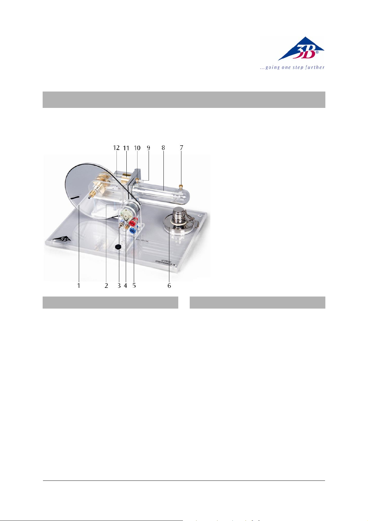
Stirling Engine G U10050
1 Flywheel with marking for
speed determination
2 Motor-generator unit with
2-stage pulley
3 Switch
4 Bulb
5 4-mm safety plugs
6 Alcohol burner
7 Temperature measure-
ment connector 1
8 Displacement piston
9 Capped hose connection
for pressure measure-
ments
10 Temperature measure-
ment connector 2
11 Working piston
12 Threaded rod M3 (con-
nected with the working
piston)
2. Description
• Pour the fuel alcohol carefully into the alco-
holburner, making sure that none of it is spilt.
• Never fill the alcoholburner as long the wick is
still smoldering or another open flame is in close
proximity.
• Immediately close the fuel container after use.
• Keep away from the open flame.
• Caution! Only extinguish the flame by fitting the
cover provided for this purpose.
The Stirling engine becomes hot when it is operated
with an open flame.
• Do not touch the displacement cylinder during
or immediately after operation of the Stirling
motor.
• Allow the Stirling engine to cool before putting it
away.
The Stirling engine can be used for qualitative and
quantitative investigations of the Stirling cycle.and
can be operated in three different modes: heat engine, heat pump and refrigerator.
The displacement cylinder and piston are made of
heat-resistant glass; the working cylinder, flywheel
and transmission covers are made of acrylic glass.
This allows a very clear observation of the individual
motion sequences at all times. The crankshafts are
equipped with ball bearings and made of hardened
steel. The connecting rods consist of wear-resistant
plastic.
The integrated motor-generator unit with a 2-stage pulley allows the generated mechanical energy to be converted into electrical energy. A switchover mechanism
permits operation of an integrated lamp or external
loads, as well as a feeding of electrical energy in order to
simulate a heat pump or refrigerator.
By attaching the thin cord supplied with the apparatus to the threaded rod on the work piston, the
stroke length can be measured.
1
Page 2

3. Technical data
5. Operation
Motor-generator unit: max. 12 V DC
2-stage pulley: 30 mm dia., 19 mm dia.
Working piston: 25 mm dia.
Path of working piston: 24 mm
25 mm
Volumetric change: 24 mm
⎛⎞
⎜⎟
2
⎝⎠
⋅π=
12 cm
Minimum volume: 32 cm³
Maximum volume: 44 cm³
Power of the Stirling motor: 1 W approx.
Dimensions: 300x220x160 mm³ approx.
Weight: 1.65 kg approx.
4. Functioning principle
An ideal Stirling cycle has 4 phases (refer to Fig. 1):
Phase 1: Isothermal change of state, during which
the air expands at constant temperature.
Phase 2: Isochoric change of state, during which the
air cools at constant volume in the regenerator.
Phase 3: Isothermal change of state, during which
the air is compressed at constant temperature.
Phase 4: Isochoric change of state, during which the
air in the regenerator is heated back to its
initial temperature.
The process that takes place in the Stirling engine
only approximates to such an ideal cycle because in
fact the four phases overlap. Gas changes from hot to
cold while the expansion is still taking place and not
all the air will yet be in the colder part of the engine
while the compression phase is occurring.
5.1 The Stirling Engine as a heat engine
• Fill the methylated-spirit burner, place it in the
recess in the base-plate, twist out about 1-2 mm
of the wick, and ignite it.
• Move the displacer piston to its farthest-back
3
position, and after a short heating-up time
(about 1-2 minutes) push the flywheel gently in
the clockwise direction (as seen from the motorgenerator unit) to set it turning (see Fig. 2).
• If necessary, adjust the tension of the drive belt
by moving the motor-generator unit.
• Turn on the filament lamp by moving the switch
to the “up” position.
• Alternatively, connect an external load through
the 4 mm sockets and drive it by moving the
switch to the “down” position.
Speed without a load: 1000 rpm approx.
Speed with a generator as the load: 650 rpm approx.
Generator voltage: 6 V DC approx.
Pressure difference: +250 hPa / -150 hPa
5.2 The Stirling motor as a heat pump or refrigerator
Additional instruments needed:
DC Power supply 15 V, 1.5 A U8521121-230
or
DC Power supply 15 V, 1.5 A U8521121-115
Digital thermometer U11818
• Insert temperature sensors into the thermome-
ter sockets and connect them to a measuring instrument (see fig. 3).
• Connect a DC voltage source through the 4 mm
sockets.
• Adjust the voltage (maximum 12 V) and operate
the Stirling engine with the switch in the “down”
position.
• Observe the increase or reduction in tempera-
ture.
In the refrigerator mode of operation, the flywheeI
rotates in the clockwise direction (as seen from the
motor-generator unit), whereas in the heat pump
mode it rotates in the anticlockwise direction.
Fig. 1 Functioning principle
(A: Displacement piston, B: Working piston)
• To switch between the two modes of operation,
reverse the polarity of the connections.
Pressure difference: +250 hPa / -150 hPa
Motor voltage: 9 V
Speed: 600 rpm
Temperature difference (with respect to 21° C):
Refrigerator: -4 K (reservoir: +6 K)
Heat pump: +13 K (reservoir: -1 K)
2
Page 3

5.3 Plotting a graph of pressure against volume
when the Stirling engine is being used as a
heat pump
Additional instruments needed:
DC Power supply 15 V, 1.5 A U8521121-230
or
DC Power supply 15 V, 1.5 A U8521121-115
3B NETlog
or
3B NETlog
3B NETlab
TM
U11300-230
TM
U11300-115
TM
U11310
Relative pressure sensor, ±1000 hPa U11322
Displacement sensor U11371
Sensor Holder for Stirling Engine G U11372
• Attach the holder for the sensor to the base plate
of the Stirling engine.
• Fit the relative pressure sensor to the bottom of
the sensor holder and the displacement sensor
at the top with the printed sides of the sensors
both facing upwards.
• Connect the nozzle marked “+” on the relative
pressure sensor to the nozzle on the working cylinder of the Stirling engine by means of the hose
included with the sensor holder (U11372) (see
Fig. 4).
• Screw the cap nut attached to the string (sup-
plied with the sensor holder) onto the thread of
the working piston, thread the string around the
displacement sensor pulley and attach a coil
spring to the threaded rod (a detailed description of how to attach the sensor to the sensor
holder is included in the instruction manual for
the sensor holder U11372).
• Connect the pressure sensor to analog input A of
the 3B NETlog
TM
unit and the displacement sen-
sor to analog input B.
• Connect a DC voltage source via the 4 mm sock-
ets.
• Adjust the voltage (maximum 12 V) and operate
the Stirling engine with the switch in the “down”
position.
• Run the 3B NETlab
TM
software, open the experiment “Stirling engine G” and plot a graph of
pressure against volume.
Fig.2 The Stirling motor as a heat engine
3
Page 4
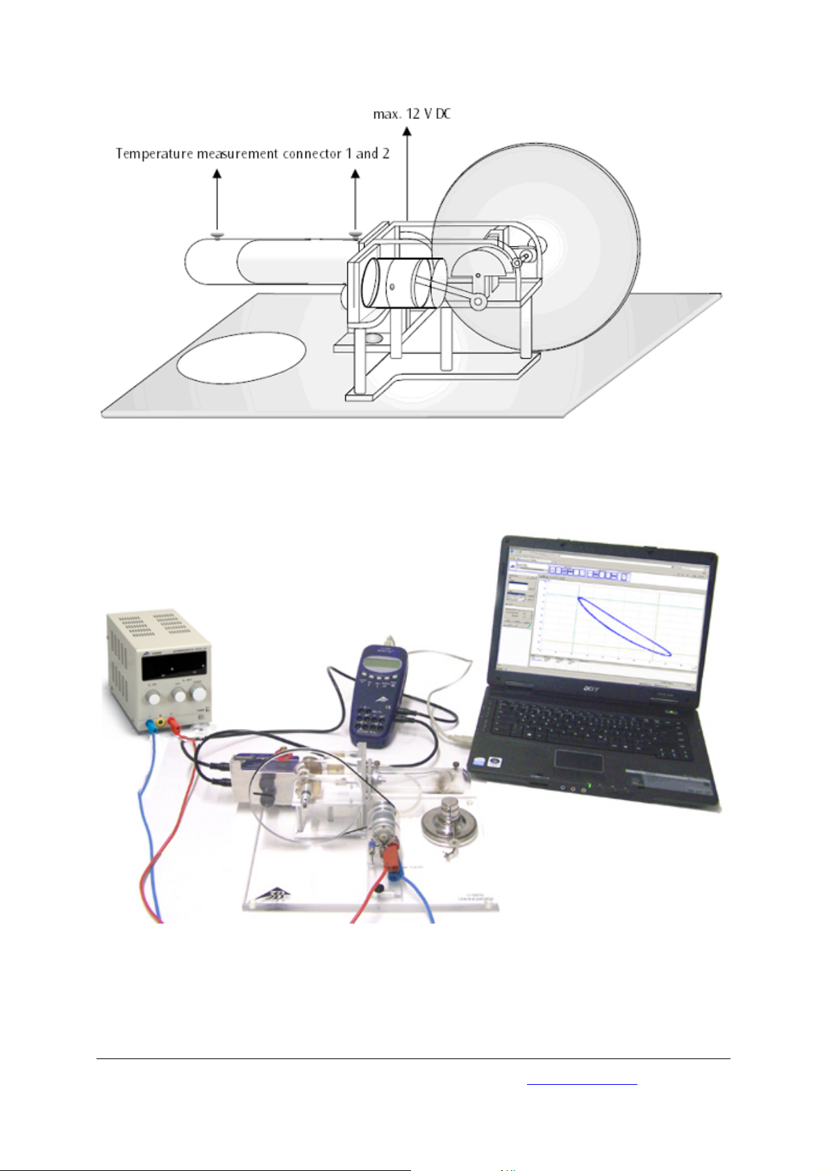
Fig. 3 The Stirling motor as a heat pump or refrigerator
Fig. 4 Recording the pressure-volume diagram
3B Scientific GmbH • Rudorffweg 8 • 21031 Hamburg • Germany • www.3bscientific.com
Subject to technical amendments
© Copyright 2011 3B Scientific GmbH
 Loading...