

Page 1

3B SCIENTIFIC
Bedienungsanleitung
05/10 THL/ALF
®
PHYSICS
Stirling-Motor D U8440450
1 Grundplatte
2 Aussparung für Teelicht
3 Heizplattenanschluss
4 Schlauchanschlussstutzen mit Verschlusskappe
5 Stativsäule
6 Schwungstange mit Massen
7 Exzenter mit Nut
8 Winkelscheibe
9 Zugfeder
10 Pleuel mit Haken
11 Arbeitskolben (Membran)
12 Obere Platte
13 Verdrängerkolben
14 Untere Platte mit elektrischer Heizung
1
Page 2

1. Sicherheitshinweise
Beim Arbeiten mit offener Flamme besteht Brandund Verletzungsgefahr!
• Beim Umgang mit offener Flamme und flüssi-
gem Wachs besondere Vorsicht walten lassen.
• Der Stirling-Motor darf nicht gleichzeitig elekt-
risch und mit Teelicht beheizt werden. Dies
kann zur Beschädigung des Geräts führen.
• Bei Betrieb des Stirling-Motors mit einem Spot-
light oder Sonnenlicht ist unbedingt darauf zu
achten, dass die roten Kunststoffteile nicht intensiver Wärmestrahlung ausgesetzt werden.
2. Beschreibung
Der Stirling-Motor D ist ein für den Unterricht optimiertes Funktionsmodell zur Demonstration der
Umwandlung von thermischer Energie in mechanische Energie sowie zur Untersuchung des Stirling’schen Kreisprozesses.
Der Verdrängerkolben bewegt sich diskontinuierlich mit einer Verweilzeit während der Erwärmung
und während der Abkühlung des Arbeitsmediums
Luft. Dadurch wird der ideale Stirling’sche Kreisprozess besser ausgefahren als dies bei kontinuierlicher Kolbenbewegung der Fall wäre und es wird
ein höherer Wirkungsgrad erreicht. Die Steuerung
des Verdrängerkolbens erfolgt über die Winkelscheibe. Bei Wärmezufuhr von unten über die
Heizplatte oder eine Kerzenflamme eilt der
Verdrängerkolben dem Arbeitskolben (Membran)
um ca. 100° voraus. Der optimale Winkel ist technisch bedingt drehzahlabhängig.
Zur Wärmezufuhr kann wahlweise eine integrierte
elektrische Heizplatte, ein Teelicht oder die gebündelte Wärmestrahlung der Sonne bzw. einer Lampe
genutzt werden. Dabei hängt die Drehrichtung
davon ab, ob die Wärmezufuhr von oben oder von
unten erfolgt.
Zur Aufnahme von pV-Diagrammen kann die
Druckmessung im Arbeitszylinder über einen
Schlauchanschlussstutzen bewerkstelligt werden
und die Volumenbestimmung durch Befestigen
eines Fadens am Haken des Pleuels zur Messung
des Hubweges des Arbeitskolbens.
3. Lieferumfang
1 Stirling-Motor D U8450450
1 Satz Transportsicherung (Schaumstoffblock,
Gummiring und Arretierstab)
4. Zubehör
Ergänzungssatz Stirling-Motor D U8440455
Der Ergänzungssatz Stirling-Motor D stellt die Zu-
behörteile bereit, die zum Aufbau der Sensoren
nötig sind. Der Satz besteht aus:
1 Auflageplatte für die Montage des Wegaufnehmers (U11371)
1 Rändelschraube zur Befestigung der Auflageplatte auf der Stativsäule
1 Stiel mit Magnetfuß für den Wegaufnehmer
1 Silikonschlauch zum Anschluss des Relativ-Druck-
sensors ±100 hPa (U11321)
1 Fadenset mit Saugnapf
2 Massestücke mit Haken je 20 g
5. Technische Daten
Heizspannung: 8 – 15 V, 1,5 A
Gasvolumen: 330 cm³ – 345 cm³
Drehzahl: 30 – 100 U/min
Abmessungen
ohne Schwungstange: 260×185×330 mm³
Schwungstange: 400 mm
Masse: 2,2 kg
2
Page 3

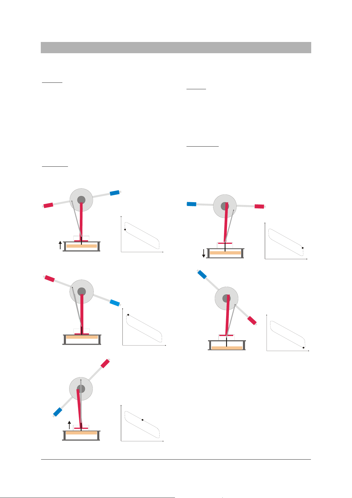
6. Funktionsprinzip
Die Funktionsweise des Stirling-Motors kann vereinfachend in die folgenden vier Takte unterteilt werden:
Wärmezufuhr:
Zur Wärmezufuhr bewegt sich der Verdrängerkol-
ben (P1) aufwärts und verdrängt die Luft nach unten in den geheizten Bereich des Verdrängungszylinders. Temperatur und Druck steigen annähernd
isochor an. Der Arbeitskolben befindet sich währenddessen im unteren Totpunkt (siehe Fig. 1). Der
Verdrängerkolben läuft dem Arbeitskolben vorraus
und erreicht den oberen Totpunkt. Die Luft hat
nun das kleinste Volumen, die höchste Temperatur
und den höchsten Druck (siehe Fig. 2).
Expansion:
Die erwärmte Luft expandiert annähernd isotherm
und treibt den Arbeitskolben (P2) nach oben. Dabei
wird mechanische Arbeit über die Kurbelwelle an
die Schwungstange abgegeben. Das Luftvolumen
wird größer, die Luft nimmt Wärme auf und der
Druck verringert sich (siehe Fig. 3).
Wärmeabgabe:
Bei der Wärmeabgabe befindet sich der Arbeitskol-
ben im oberen Totpunkt während sich der Verdrängerkolben (P1) abwärts bewegt und die Luft in den
oberen Bereich des Verdrängungszylinders verdrängt. Die Luft wird abgekühlt und die obere
Platte nimmt Wärme auf. Der Verdrängerkolben
erreicht den unteren Totpunkt (siehe Fig. 4 und 5).
Kompression:
Die abgekühlte Luft wird isotherm durch den sich
nach unten bewegenden Arbeitskolben komprimiert. Die mechanische Arbeit hierfür wird durch
die Schwungstange geliefert (siehe Fig. 6).
P1
Fig. 1 Wärmezufuhr
Fig. 2 Wärmezufuhr
P
P1
V
Fig. 4 Wärmeabgabe
P
V
Fig. 5 Wärmeabgabe
P
V
P
V
P2
Fig. 3 Expansion
P
P2
V
Fig. 6 Kompression
P
V
3
Page 4

7. Erstinbetriebnahme
• Netzgerät an das Buchsenpaar anschließen und
eine Heizspannung bis 12 V (ca. 1,5 A) einstellen.
• Nach einer Aufheizzeit von ca. 1 bis 2 Minuten
Schwungstange mit Drehrichtung im Uhrzeigersinn bei Blickrichtung von vorn auf den Motor anstoßen.
• Falls der Stirling-Motor sich nicht selbständig
weiterdreht, den Anstoß nach ca. 1 min wiederholen.
Die Motordrehzahl verhält sich annähernd proportional zur Temperaturdifferenz zwischen oberer
Platte und unterer Platte und ist damit weitgehend
von der zugeführten Wärme abhängig.
• Heizspannung schrittweise bis auf 8 V reduzie-
ren und Abnahme der Drehzahl beobachten.
8.1.2 Heizung mit einer Kerzenflamme
• Teelicht entzünden und auf eine hitzeresisten-
te Unterlage stellen.
• Stirling-Motor mit seiner zentrischen Ausspa-
Fig. 7 Stirling-Motor in gesichertem Zustand
• Gummiring (3) vom Sicherungshaken (4) für
den Verdrängerkolben abnehmen und Haken
aus dem Schlauchanschlussstutzen herausziehen.
• Schlauchanschlussstutzen mit roter Verschluss-
kappe (5) abdichten.
• Schaumstoffblock (2) zwischen Stativsäule und
Schwungmasse entnehmen.
• Arretierschraube (1) lösen, Schwungstange
horizontal im Gleichgewicht ausrichten und Ar-
retierschraube wieder festziehen.
Der Motor ist damit betriebsbereit.
Der Transport des Stirling-Motors darf nur mit
gesichertem Verdrängerkolben erfolgen.
• Dazu Verschlusskappe vom Schlauchanschluss-
stutzen entfernen, Sicherungshaken wieder
einsetzen und mit dem Gummiring sichern.
• Schwungstange arretieren.
8. Bedienung
8.1 Betrieb als Wärmekraftmaschine
8.1.1 Elektrische Heizung
Zur elektrischen Beheizung des Stirling-Motors ist
folgendes Netzgerät empfehlenswert:
1 DC-Netzgerät 15 V, 1,5 A (230 V, 50/60 Hz)
U8521121-230
oder
1 DC-Netzgerät 15 V, 1,5 A (115 V, 50/60 Hz)
U8521121-115
rung über das Teelicht stellen.
• Einige Minuten abwarten bis sich die untere
Platte erhitzt hat.
• Schwungstange mit Drehrichtung im Uhrzei-
gersinn bei Blickrichtung von vorn auf den Motor anstoßen.
• Falls der Stirling Motor sich nicht selbständig
weiterdreht, den Anstoß nach ca. 1 min wiederholen.
8.1.3 Heizung mit einer Lampe (Spotlight)
• Obere Platte des Stirling-Motors von oben aus
einer Entfernung von 1 bis 2 cm einer 60-WGlühlampe mit eingeschränktem Abstrahlwinkel (Spotlight) bestrahlen. Die untere Platte
kühlt in diesem Falle die Luft im Verdrängerzylinder ab.
• Alternativ die obere Platte mit durch einen
Hohlspiegel gebündeltes Sonnenlicht beheizen.
• Etwa 8 bis 10 Minuten abwarten bis sich die
obere Platte erhitzt hat.
• Schwungstange mit Drehrichtung gegen den
Urzeigerrichtung bei Blickrichtung von vorn
auf den Motor anstoßen.
• Falls der Stirling-Motor sich nicht selbständig
weiterdreht, den Anstoß nach einiger Zeit wiederholen.
8.2 Aufnahme des pV-Diagramms
Zur Aufnahme des pV-Diagramms sind folgende
Geräte zusätzlich erforderlich:
1 Ergänzungssatz Stirling-Motor D U8440455
1 3B NETlog™ (230 V, 50/60 Hz) U11300-230
oder
4
Page 5

1 3B NETlog™ (115 V, 50/60 Hz) U11300-115
1 3B NETlab™ U11310
1 Relativ-Drucksensor ±100 hPa U11321
1 Wegaufnehmer U11371
1 DC-Netzgerät 15 V, 1,5 A (230 V, 50/60 Hz)
U8521121-230
oder
1 DC-Netzgerät 15 V, 1,5 A (115 V, 50/60 Hz)
U8521121-115
• Relativ-Drucksensor mit dem Silikonschlauch
an den Schlauchanschlussstutzen anschließen.
• Auflageplatte mit der Rändelschraube auf der
Stativsäule befestigen.
• Stiel mit Magnetfuß in den Wegaufnehmer
schrauben und auf die Auflageplatte platzieren.
• Schraube an der Rolle des Wegaufnehmers
lösen. Faden ein Mal um die Rolle legen, aus
der Aussparung herausführen und eine Schlau-
fe um die Schraube legen. Mit der Schraube
den Faden fixieren (siehe Fig. 8).
• Das eine Ende des Fadens am Pleuelhaken
befestigen, ans andere Ende ein Massestück
hängen.
• Einen zweiten Faden mittels des Saugnapfs auf
der Grundplatte befestigen. Faden über die Nut
im Exzenter legen und das zweite Massestück
als Last ans freie Ende hängen.
Fig. 8 Schematische Darstellung der Führung des Fadens
um die Rolle am Wegaufnehmer (U11371)
• Dieses Massestück dient als Last und sorgt
dafür, dass das pV-Diagramm besser ausgefahren wird.
• Netzgerät an die Heizplatte anschließen und
eine Spannung bis 12 V (ca. 1,5 A) einstellen.
• Beide Sensoren am Interface 3B NETlog™ an-
schließen.
• Software in Computer starten.
• Nach der Aufwärmzeit den Stirling-Motor durch
Anstoßen im Uhrzeigersinn starten.
• Messung in der Software starten. Daten aus-
werten.
Fig. 9 Experimenteller Aufbau zur Aufnahme des pV-Diagramms
5
Page 6

Fig. 10 Druck-Volumen-Diagramm des Stirling-Motors D
Elwe Didactic GmbH • Steinfelsstr. 6 • 08248 Klingenthal • Deutschland • www.elwedidactic.com
3B Scientific GmbH • Rudorffweg 8 • 21031 Hamburg • Deutschland • www.3bscientific.com
Technische Änderungen vorbehalten
© Copyright 2010 3B Scientific GmbH
Page 7

3B SCIENTIFIC
Stirling Engine D U8440450
Instruction manual
05/10 THL/ALF
®
PHYSICS
1 Base plate
2 Hole for tea candle
3 Hot plate connector
4 Hose nozzle with sealing cap
5 Stand
6 Rotor with weights
7 Eccentric with groove
8 Torque disc
9 Tension spring
10 Connector rod with hook
11 Working piston (membrane)
12 Upper plate
13 Displacement piston
14 Lower plate with electric heater
1
Page 8

1. Safety instructions
When working with naked flames, there is always a
risk of fire and injury.
• Take extra care when handling naked flames
and molten wax.
• The Stirling engine may not be heated electri-
cally at the same time as it is being heated by a
candle. There is a risk of damage to the
equipment.
• When operating the Stirling engine using a
spotlight or sunlight, it is essential that care be
taken not to expose the red plastic components
to intense heat.
2. Description
The Stirling engine D is a fully functional model,
optimised for teaching purposes and intended to
demonstrate how thermal energy can be converted
to mechanical energy as well as for investigating
the Stirling cycle.
The displacement piston moves discontinuously
with a delay during heating and cooling of the
working medium, air. This emulates the ideal Stirling cycle better than would be the case with a
continuously moving piston and also makes for
improved efficiency. The motion of the displacement piston is controlled by the torque disc. When
heat is supplied from below, either by means of the
electric heater or by a candle flame, the displacement piston precedes the working piston (membrane) by about 100°. The optimum angle is technically dependent on the speed of rotation.
Heat can be supplied either by the built-in electric
hot plate, a candle or by focussed heat radiation
from the sun or by a lamp. The direction of rotation depends on whether the heat is supplied from
above or below.
To record pV diagrams, the pressure in the working
cylinder can be measured by means of a hose attached to the nozzle provided and the volume can
be determined by attaching a thread to the hook
on the connecting rod in order to measure the
stroke of the working piston.
3. Scope of delivery
1 D-series Stirling engine U8450450
1 Set of transport packaging (foam plastic block,
rubber band and retaining rod)
4. Accessories
Supplementary set for Stirling engine D
U8440455
The supplementary set for the D-series Stirling
engine provides accessories necessary for constructing sensors. The set consists of the following:
1 Base plate for assembly of displacement sensor
(U11371)
1 Knurled screw for attaching the base plate to the
stand
1 Stem with a magnetic base for the displacement
sensor
1 Silicone tube for attaching a relative pressure
sensor, ±100 hPa (U11321)
1 Set of threads with suction cup
2 Weights with hook, both 20 g
5. Technical data
Heater voltage: 8 – 15 V, 1.5 A
Gas volume: 330 cm³ – 345 cm³
Speed: 30 – 100 rpm
Dimensions
not including rotor: 260×185×330 mm
3
Rotor: 400 mm
Weight: 2.2 kg
2
Page 9
6. Operating principle
The principle of a how a Stirling engine works can be
divided, in simplified form, into the following four
processes:
Heating:
During the heating phase, the displacement piston
(P1) moves upwards so that air is displaced down
into the heated part of the displacement cylinder.
Temperature and pressure both rise in a fashion
that is almost isochoric. The working piston is in its
lower rest position (bottom dead centre) at this
point (see Fig. 1). The displacement piston moves in
advance of the working piston till it reaches its top
dead centre position. This is the point where the
air is at its lowest volume, but highest temperature
and pressure (see Fig. 2).
Expansion:
The heated air expands almost isothermally, thus
P
forcing the working piston (P2) upwards. In the
process, mechanical work is transferred via the shaft
to the rotor. The volume of air increases as the air
absorbs heat and the pressure reduces (see Fig. 3).
Cooling:
Cooling occurs while the working piston is at top
dead centre and the displacement piston (P1) is on
its downstroke, forcing air to move into the upper
part of the displacement cylinder. The air then
cools and the upper plate absorbs heat. The displacement piston finally reaches bottom dead
centre (see Figs. 4 and 5).
Compression:
The cooler air is compressed isothermally by the
working piston moving downwards. The mechanical work needed for this is supplied by the rotor
acting as a flywheel (see Fig. 6).
Fig. 3 Expansion
P
P1
Fig. 1 Heating
Fig. 2 Heating
V
P1
Fig. 4 Cooling
P
P
V
Fig. 5 Cooling
P
P2
V
3
Page 10

P
P2
Fig. 6 Compression
7. Getting the engine ready for use
Fig. 7 Stirling engine as secured for storage
• Remove the rubber band (3) from the securing
hook (4) for the displacement piston and take
the hook out of the hose nozzle.
• Seal off the hose nozzle with the red cap (5).
• Remove the foam plastic block (2) between the
stand and the rotor weight.
• Undo the securing screw (1), align the rotor
horizontally so that it is balanced and tighten
the screw back up again.
The engine is then ready for use.
The Stirling engine must not be transported unless
the displacement piston is secured.
• To secure it, take the sealing cap of the hose
nozzle, put the securing hook back in and se-
cure it in place with the rubber band.
• Secure the rotor as well.
8. Operation
8.1 Operation as a heat engine
8.1.1 Electric heating
The following power supplies are recommended for
heating the Stirling engine electrically:
1 DC power supply, 15 V, 1.5 A (230 V, 50/60 Hz)
U8521121-230
or
1 DC power supply, 15 V, 1.5 A (115 V, 50/60 Hz)
U8521121-115
• Connect the power supply to the pair of sockets
and set the heater voltage up to 12 V (1.5 A
approx.).
• After heating for about one or two minutes,
start the engine by pushing the rotor clockwise
as seen from the front of the engine.
• If the Stirling engine fails to keep moving of its
own accord, wait about a minute longer and
push the rotor round again.
The speed of the engine is nearly proportional to
the difference in temperature between the top
plate and the bottom plate and is thus largely dependent on the heat supplied.
• Reduce the heater voltage in steps down to
about 8 V and observe how the speed reduces.
8.1.2 Heating via a candle flame
• Light a tea candle and place it on a heat-
resistant mat.
• Place the Stirling engine over the candle so the
hole in the middle is over the flame.
• Wait for several minutes until the lower plate
has heated up.
• Push the rotor clockwise as seen from the front
of the engine.
• If the Stirling engine fails to keep moving of its
own accord, wait about a minute longer and
push the rotor round again.
8.1.3 Heating via a lamp (spotlight)
• Shine a light on the top plate from about 1 or 2
cm using a lamp with a 60-W bulb and a focussed beam (spotlight). In this case it is the lower
plate that will cool the air in the displacement
cylinder.
• Alternatively, the upper plate can be heated
via sunlight focused using a concave mirror.
• Wait for about 8 to 10 minutes until the upper
plate has heated up.
• Push the rotor anti-clockwise as seen from the
front of the engine.
4
Page 11

• If the Stirling engine fails to keep moving of its
own accord, wait about a minute longer and
push the rotor round again.
8.2 Recording a pV diagram
To record a pV diagram, the following pieces of
equipment are also required:
1 Supplementary set for Stirling engine D U8440455
1 3B NETlog™ unit (230 V, 50/60 Hz) U11300-230
or
1 3B NETlog™ unit (115 V, 50/60 Hz) U11300-115
1 3B NETlab™ program U11310
1 Relative pressure sensor, ±100 hPa U11321
1 Displacement sensor U11371
1 DC power supply, 15 V, 1.5 A (230 V, 50/60 Hz)
U8521121-230
or
1 DC power supply, 15 V, 1.5 A (115 V, 50/60 Hz)
U8521121-115
• Connect the relative pressure sensor to the
hose nozzle using silicone tubing.
• Attach the base plate to the stand using the
knurled screw.
• Screw the stem with the magnetic base into the
displacement sensor and place it on the base
Fig. 8 Schematic illustration of how the thread is wound
around the pulley of the displacement sensor (U11371)
• Connect the power supply to the heater plate
and set the voltage up to 12 V (1.5 A approx.).
• Connect both sensors to the 3B NETlog™ inter-
face.
• Run the software on a computer.
• After the Stirling engine has heated up, start it
running by pushing the rotor in a clockwise direction.
• Start a measurement using the software and
evaluate the data.
plate.
• Loosen the screw on the displacement sensor’s
pulley. Wind a thread once around the pulley
and lead it out of the recess placing a loop
around the screw. Use the screw to fix the
thread in place (see Fig. 8).
• Attach one end of the thread to the hook of the
connector rod and suspend a weight from the
other end.
• Use the suction pad to attach a second thread
to the base plate. Thread this over the groove
in the eccentric and use the other weight as a
load on the free end.
• This load ensures that the pV diagram comes
out better.
5
Page 12

Fig. 9 Experiment set-up for recording a pV diagram
Fig. 10 Pressure-volume diagram for D-series Stirling engine
Elwe Didactic GmbH • Steinfelsstr. 6 • 08248 Klingenthal • Germany • www.elwedidactic.com
3B Scientific GmbH • Rudorffweg 8 • 21031 Hamburg • Germany • www.3bscientific.com
Subject to technical amendments
© Copyright 2010 3B Scientific GmbH
Page 13

3B SCIENTIFIC
Moteur Stirling D U8440450
Instructions d’utilisation
05/10 THL/ALF
®
PHYSICS
1 Plaque de travail
2 Evidement pour bougie chauffe-plat
3 Connexion pour plaque chauffante
4 Raccord de tuyau flexible avec capuchon
5 Colonne du statif
6 Tige oscillante avec masses
7 Excentrique avec rainure
8 Disque angulaire
9 Ressort de traction
10 Bielle avec crochet
11 Piston moteur (membrane)
12 Plaque supérieure
13 Piston déplaceur
14 Plaque inférieure avec chauffage électrique
1
Page 14

1. Consignes de sécurité
Lors de travaux avec une flamme nue, un risque
d’incendie et de blessure existe !
• Pour la manipulation de flammes nues et de
cire liquide, faites preuve d’une attention par-
ticulière.
• Le moteur Stirling ne doit pas être chauffé
électriquement et avec la bougie chauffe-plat
simultanément. Ceci peut entraîner des dom-
mages au niveau de l’appareil.
• Pendant le fonctionnement du moteur Stirling
avec un projecteur ou la lumière du soleil, il
est impératif de veiller à ce que les pièces rou-
ges en plastique ne soient pas exposées à un
rayonnement thermique intense.
2. Description
Le moteur Stirling D est un modèle de description
optimisé pour les cours afin de démontrer la
conversion d’énergie thermique en énergie mécanique ainsi que pour l’étude du cycle de Stirling.
Le piston déplaceur se déplace par intermittence
avec une temporisation pendant le chauffage et
pendant le refroidissement du fluide moteur – l’air.
Ainsi, le cycle de Stirling idéal est mieux développé
qu’avec un déplacement continu du piston et un
rendement plus élevé est atteint. La régulation du
piston déplaceur s’effectue par le biais du disque
angulaire. En cas d’apport de chaleur par le bas
avec la plaque chauffante ou une flamme de bougie, le piston déplaceur est en avance d’environ
100° par rapport au piston moteur (membrane).
L’angle optimal dépend de la vitesse en raison de
la technique.
Pour l’apport de chaleur, une plaque chauffante
électrique intégrée, une bougie chauffe-plat ou le
rayonnement thermique focalisé du soleil ou d’une
lampe peuvent être utilisés au choix. Pour cela, le
sens de rotation dépend du fait que l’apport de
chaleur se fait par le haut ou par le bas.
Pour l’enregistrement de diagrammes pV, la mesure de pression dans le cylindre moteur peut être
effectuée par le biais d’un raccord de tuyau flexible
et la détermination du volume en fixant un fil sur
le crochet de la bielle pour mesurer la course du
piston moteur.
3. Volume de livraison
1 Moteur Stirling D U8450450
1 Jeu de sécurités de transport (bloc en mousse
synthétique, bague de caoutchouc et tige
d’arrêt)
4. Accessoires
Kit d’extension Moteur Stirling D U8440455
Le kit d’extension Moteur Stirling D prévoit les
pièces accessoires nécessaires pour le montage des
capteurs. Le kit se compose de :
1 plaque d’appui pour le montage du capteur de
déplacement (U11371)
1 vis moletée pour la fixation de la plaque d’appui
sur la colonne du statif
1 tige avec support aimanté pour le capteur de
déplacement
1 tuyau flexible en silicone pour la connexion du
capteur de pression relative ±100 hPa (U11321)
1 jeu de fils avec ventouse
2 masses avec crochet de 20 g chacune
5. Caractéristiques techniques
Tension de chauffage : 8 – 15 V, 1,5 A
Volume de gaz : 330 cm³ – 345 cm³
Vitesse : 30 – 100 U/min
Dimensions
sans tige oscillante : 260×185×330 mm³
Tige oscillante : 400 mm
Poids : 2,2 kg
2
Page 15

6. Principe de fonctionnement
Pour simplifier, le principe de fonctionnement du
moteur Stirling peut être divisé en quatre phases
suivantes :
Apport de chaleur :
Pour l’apport de chaleur, le piston déplaceur (P1)
se déplace vers le haut et refoule l’air vers le bas
dans la zone chauffée du piston déplaceur. La
température et la pression augmentent approximativement de façon isochore. Pendant ce temps, le
piston moteur se trouve au point mort bas (cf.
Fig. 1). Le piston déplaceur dépasse le piston moteur et atteint le point mort haut. L’air présente
désormais le volume le plus faible, la température
la plus élevée et la pression la plus haute (cf.
Fig. 2).
Détente :
L’air chauffé se détend approximativement de
façon isotherme et pousse le piston moteur (P2)
vers le haut. Pour cela, le travail mécanique est
transmis à la tige oscillante par le biais du vilebrequin. Le volume d’air augmente, l’air absorbe la
chaleur et la pression diminue (cf. Fig. 3).
Dégagement de chaleur :
Pour le dégagement de chaleur, le piston moteur
se trouve au point mort haut tandis que le piston
déplaceur (P1) se déplace vers le bas et l’air est
refoulé dans la zone supérieure du piston déplaceur. L’air est refroidi et la plaque supérieure absorbe la chaleur. Le piston déplaceur atteint le
point mort bas (cf. Fig. 4 et 5).
Compression :
L’air refroidi est comprimé de façon isotherme par
le biais du déplacement vers le bas du piston moteur. Pour cela, le travail mécanique est fourni par
la tige oscillante (cf. Fig. 6).
P1
Fig. 1 Apport de chaleur
Fig. 2 Apport de chaleur
P
P1
V
Fig. 4 Dégagement de chaleur
P
V
Fig. 5 Dégagement de chaleur
P
V
P
V
P2
Fig. 3 Détente
P
P
P2
V
V
Fig. 6 Compression
3
Page 16

7. Première mise en service
• Raccordez l’alimentation à la paire de douilles
et réglez la tension de chauffage jusqu’à 12 V
(env. 1,5 A).
• Après un temps d’échauffement d’env. 1 à
2 minutes, poussez la tige oscillante contre le moteur avec un sens de rotation dans le sens des aiguilles d’une montre en regardant de l’avant.
• Si le moteur Stirling ne continue pas de tour-
ner tout seul, répétez le déclenchement au
bout d’environ 1 min.
La vitesse du moteur se comporte approximativement
proportionnellement à l’écart de température entre la
plaque supérieure et la plaque inférieure et dépend
ainsi étroitement de la température appliquée.
• Réduisez progressivement la tension de chauffage
à 8 V et observez la diminution de la vitesse.
8.1.2 Chauffage avec une flamme de bougie
• Allumez la bougie chauffe-plat et placez-la sur
un support thermorésistant.
• Placez le moteur Stirling avec son évidement
Fig. 7 Moteur Stirling à l’état verrouillé
• Retirez la bague de caoutchouc (3) du crochet
de sécurité (4) pour le piston déplaceur et en-
levez le crochet du raccord de tuyau flexible.
• Bouchez le raccord de tuyau flexible avec le
capuchon rouge (5).
• Retirez le bloc en mousse synthétique (2) entre
la colonne du statif et la masse oscillante.
• Desserrez la vis d’arrêt (1), orientez la tige oscil-
lante à l’horizontale en équilibre statique et
serrez de nouveau la vis d’arrêt.
Le moteur est ainsi opérationnel.
Le transport du moteur Stirling doit être effectué
uniquement avec le piston déplaceur bloqué.
• Pour cela, retirez le capuchon du raccord de
tuyau flexible, replacez le crochet de sécurité
et bloquez-le avec la bague de caoutchouc.
• Bloquez la tige oscillante.
8. Manipulation
8.1 Fonctionnement en tant que moteur ther-
mique
8.1.1 Chauffage électrique
Pour le chauffage électrique du moteur Stirling,
l’alimentation suivante est recommandée :
Alimentation CC 15 V, 1,5 A (230 V, 50/60 Hz)
U8521121-230
ou
1 alimentation CC 15 V, 1,5 A (115 V, 50/60 Hz)
U8521121-115
central sur la bougie chauffe-plat.
• Patientez quelques minutes jusqu’à ce que la
plaque inférieure soit chauffée.
• Poussez la tige oscillante contre le moteur avec
un sens de rotation dans le sens des aiguilles
d’une montre en regardant de l’avant.
• Si le moteur Stirling ne continue pas de tour-
ner tout seul, répétez le déclenchement au
bout d’environ 1 min.
8.1.3 Chauffage avec une lampe (projecteur)
• Illuminez la plaque supérieure du moteur
Stirling par le haut à une distance de 1 à 2 cm
d’une ampoule électrique de 60 W avec un angle de rayonnement limité (projecteur). Dans
ce cas, la plaque inférieure refroidit l’air dans
le piston déplaceur.
• Une alternative consiste à chauffer la plaque
supérieure avec la lumière du soleil focalisée à
travers un miroir concave.
• Patientez entre 8 et 10 minutes jusqu’à ce que
la plaque supérieure soit chauffée.
• Poussez la tige oscillante contre le moteur avec
un sens de rotation dans le sens inverse des aiguilles d’une montre en regardant de l’avant.
• Si le moteur Stirling ne continue pas de tour-
ner tout seul, répétez le déclenchement au
bout d’un moment.
8.2 Enregistrement du diagramme pV
Pour l’enregistrement du diagramme pV, les appareils suivants sont également nécessaires :
1 kit d’extension Moteur Stirling D U8440455
1 capteur de pression relative ±100 hPa U11321
1 capteur de déplacement U11371
4
Page 17

1 3B NETlog™ (230 V, 50/60 Hz) U11300-230
ou
1 3B NETlog™ (115 V, 50/60 Hz) U11300-115
1 3B NETlab™ U11310
1 alimentation CC 15 V, 1,5 A (230 V, 50/60 Hz)
U8521121-230
ou
1 alimentation CC 15 V, 1,5 A (115 V, 50/60 Hz)
U8521121-115
• Raccordez le capteur de pression relative au
raccord de tuyau flexible à l’aide du tuyau
flexible en silicone.
• Fixez la plaque d’appui sur la colonne du statif
à l’aide de la vis moletée.
• Vissez la tige avec support aimanté dans le
capteur de déplacement et placez le tout sur la
plaque d’appui.
• Desserrez la vis sur la poulie du capteur de
déplacement. Faites passer le fil une fois au-
tour de la poulie, faites-le sortir de l’évidement
et faites passer une boucle autour de la vis.
Fixez le fil avec la vis (cf. Fig. 8).
• Fixez une extrémité du fil au niveau du crochet
de la bielle, attachez une masse marquée à
l’autre extrémité.
• Fixez un deuxième fil sur la plaque de travail à
l’aide de la ventouse. Faites passer le fil au-
dessus de la rainure dans l’excentrique et ac-
crochez la deuxième masse marquée comme
charge sur l’extrémité libre.
Fig. 8 Représentation schématique du guidage du fil
autour de la poulie au niveau du capteur de déplacement (U11371)
• Cette masse marquée sert de charge et permet
une meilleure production du diagramme pV.
• Raccordez l’alimentation à la plaque chauf-
fante et réglez la tension jusqu’à 12 V (env.
1,5 A).
• Raccordez les deux capteurs sur l’interface
3B NETlog™.
• Lancez le logiciel de l’ordinateur.
• Après le temps de réchauffage, démarrez le
moteur Stirling en le déclenchant dans le sens
des aiguilles d’une montre.
• Démarrez la mesure avec le logiciel. Interpré-
tez les données.
Fig. 9 Montage expérimental pour l’enregistrement du diagramme pV
5
Page 18

Fig. 10 Diagramme pression-volume du moteur Stirling D
Elwe Didactic GmbH • Steinfelsstr. 6 • 08248 Klingenthal • Allemagne • www.elwedidactic.com
3B Scientific GmbH • Rudorffweg 8 • 21031 Hambourg • Allemagne • www.3bscientific.com
Sous réserve de modifications techniques
© Copyright 2010 3B Scientific GmbH
Page 19

FISICA 3B SCIENTIFIC
Motore Stirling D U8440450
Istruzioni per l'uso
05/10 THL/ALF
®
1 Piastra di base
2 Incavo per lumino
3 Collegamento piastra di riscaldamento
4 Attacco per tubo flessibile con tappo
5 Montante dello stativo
6 Asta centrifuga con pesi
7 Eccentrico con scanalatura
8 Disco goniometrico
9 Molla di trazione
10 Biella con gancio
11 Cilindro di lavoro (membrana)
12 Piastra superiore
13 Pistone di compressione
14 Piastra inferiore con riscaldamento elettrico
1
Page 20

1. Norme di sicurezza
Pericolo di bruciature e lesioni quando si maneggiano fiamme libere!
• Durante l’uso di fiamme libere e cera liquida
agire prestando particolare attenzione.
• Non riscaldare il motore Stirling contempora-
neamente in maniera elettrica e con il lumino.
Ciò potrebbe causare danni all’apparecchio.
• In caso di impiego del motore Stirling con
spotlight o luce solare, prestare attenzione e
assicurarsi che le parti in plastica di colore ros-
so non siano sottoposte a radiazioni termiche
intense.
2. Descrizione
Il motore Stirling D è un modello funzionale ottimizzato per la didattica per dimostrare la trasformazione dell’energia termica in meccanica nonché
per lo studio dei cicli di Stirling.
Il pistone di compressione si sposta in modo discontinuo con un tempo di sosta durante il riscaldamento e durante il raffreddamento del fluido di
esercizio aria. In tal modo, il ciclo di Stirling ideale
viene eseguito meglio di quanto avverrebbe con un
movimento continuo del pistone, ottenendo una
maggiore efficacia. Il pistone di compressione viene comandato per mezzo del disco goniometrico.
Alimentando il calore dal basso mediante la piastra
di riscaldamento oppure con la fiamma di una
candela, il pistone di compressione precede quello
di lavoro (membrana) di circa 100°. Per ragioni
tecniche, l’angolo ottimale dipende dal numero di
giri.
Per l’alimentazione del calore si può utilizzare a
scelta una piastra di riscaldamento elettrica integrata, un lumino oppure la radiazione termica
focalizzata della luce solare o di una lampada. La
direzione di rotazione dipende in questo caso dalla
direzione, dall’alto o dal basso, di provenienza
dell’alimentazione termica.
Per registrare i diagrammi pV, è possibile misurare
la pressione nel cilindro di lavoro tramite l’attacco
del tubo flessibile e determinare il volume fissando
un filo sul gancio della biella per la misurazione
della corsa del pistone di lavoro.
3. Contenuto della fornitura
1 motore Stirling D U8450450
1 kit di sicurezza per il trasporto (blocco in schiuma
espansa, anello elastico e barra d’arresto)
4. Accessori
Kit aggiuntivo Motore Stirling D U8440455
Il kit aggiuntivo Motore Stirling D contiene gli ac-
cessori necessari al montaggio dei sensori. Il kit
comprende:
1 piastra di supporto per il montaggio del rilevatore di corsa (U11371)
1 vite a testa zigrinata per il fissaggio della piastra
di supporto sul montante dello stativo
1 asta con piede magnetico per il rilevatore di
corsa
1 tubo di silicone per il raccordo del sensore di
pressione relativa ±100 hPa (U11321)
1 set di fili con ventosa
2 pesi con gancio da 20 g ciascuno
5. Dati tecnici
Tensione di riscaldamento: 8 – 15 V / 1,5 A
Volume del gas: 330 cm³ – 345 cm³
Numero di giri: 30 – 100 giri/min
Dimensioni
senza asta centrifuga: 260×185×330 mm³
Asta centrifuga: 400 mm
Peso: 2,2 kg
2
Page 21

6. Principio di funzionamento
Il funzionamento del motore Stirling può essere suddiviso per semplificare nei quattro tempi indicati di
seguito:
Apporto di calore:
Per l’apporto di calore, il pistone di compressione
(P1) si muove in avanti e sposta l’aria verso il basso
nell’area riscaldata del cilindro di compressione.
Temperatura e pressione salgono in maniera pressoché isocora. In questa fase, il pistone di lavoro si
trova al punto morto inferiore (v. Fig. 1). Il pistone
di compressione precede quello di lavoro e raggiunge il punto morto superiore. L’aria ha il volume più basso, la temperatura maggiore e la massima pressione (v. Fig. 2).
Espansione:
L’aria riscaldata si espande in maniera pressoché iso-
termica e sposta il pistone di lavoro (P2) verso l’alto.
Il lavoro meccanico viene quindi ceduto all’asta
centrifuga tramite l’albero a gomiti. Il volume
dell’aria aumenta, l’aria assorbe calore e la pressione si riduce (v. Fig. 3).
Cessione del calore:
Nel caso della cessione di calore, il pistone di lavo-
ro si trova presso il punto morto superiore, mentre
il pistone di compressione (P1) arretra e sposta
l’aria nell’area superiore del cilindro di compressione. L’aria si raffredda e la piastra superiore assorbe calore. Il pistone di compressione raggiunge il
punto morto inferiore (v. Figg. 4 e 5).
Compressione:
L’aria raffreddata viene compressa in modo isoter-
mico dal pistone di lavoro che si sposta verso il basso. Il lavoro meccanico necessario a questo proposito viene svolto dall’asta centrifuga (v. Fig. 6).
P1
Fig. 1 Apporto di calore
Fig. 2 Apporto di calore
P
P1
V
Fig. 4 Cessione di calore
P
V
Fig. 5 Cessione di calore
P
V
P
V
P2
Fig. 3 Espansione
P
P2
V
Fig. 6 ompressione
P
V
3
Page 22

7. Prima messa in funzione
• Collegare l’alimentatore alla coppia di jack e
impostare una tensione di riscaldamento fino a
12 V (circa 1,5 A).
• Dopo un tempo di riscaldamento di circa 1-2
minuti, avviare l’asta centrifuga con senso di
rotazione orario guardando il motore dal davanti.
• Se il motore Stirling non comincia a ruotare
autonomamente, ripetere l'operazione di avvio
dopo circa 1 min.
Il numero di giri del motore si comporta in maniera pressoché proporzionale alla differenza di temperatura fra piastra superiore e piastra inferiore e
dipende sostanzialmente dal calore apportato.
• Diminuire gradualmente la tensione di riscal-
damento fino a 8 V ed osservare il calo del
numero di giri.
8.1.2 Riscaldamento con la fiamma di una
candela
• Accendere il lumino e collocarlo su un piano di
Fig. 7 Motore Stirling in condizioni di sicurezza
• Rimuovere l’anello elastico (3) dal gancio di
sicurezza (4) per il pistone di compressione ed
estrarre il gancio dall’attacco del tubo flessibile.
• Chiudere a tenuta l’attacco del tubo flessibile
utilizzando il tappo rosso (5).
• Rimuovere il blocco in schiuma espansa (2) fra
il montante dello stativo e il peso dell’asta centrifuga.
• Allentare la vite di fermo (1), portare l’asta
centrifuga in posizione di equilibrio orizzonta-
le e serrare nuovamente la vite.
Il motore è ora pronto all’uso.
Il trasporto del motore Stirling è consentito sola-
mente se il pistone di compressione è stato messo
in sicurezza.
• A questo scopo, rimuovere il tappo del raccor-
do del tubo flessibile, reinserire il gancio di si-
curezza e assicurare con l’anello elastico.
• Bloccare l’asta centrifuga.
8. Funzionamento
appoggio resistente al calore.
• Sistemare il motore Stirling con l’incavo centra-
le sopra il lumino.
• Attendere qualche minuto affinché la piastra
inferiore si scaldi.
• Avviare l’asta centrifuga con senso di rotazione
orario guardando il motore dal davanti.
• Se il motore Stirling non comincia a ruotare
autonomamente, ripetere l'operazione di avvio
dopo circa 1 min.
8.1.3 Riscaldamento con una lampada (spotlight)
• Irradiare la piastra superiore del motore Stir-
ling dall’alto da una distanza di circa 1-2 cm
con una lampadina da 60 W con angolo di irradiazione limitato (spotlight). La piastra inferiore raffredda in questo caso l’aria all’interno
del cilindro di compressione.
• In alternativa, riscaldare la piastra superiore
con luce solare focalizzata attraverso uno specchio concavo.
• Attendere circa 8-10 minuti affinché la piastra
superiore si scaldi.
• Avviare l’asta centrifuga con senso di rotazione
antiorario guardando il motore dal davanti.
8.1 Funzionamento come motore termico
8.1.1 Riscaldamento elettrico
Per il riscaldamento elettrico del motore Stirling si
consiglia il seguente alimentatore:
Alimentatore CC 15 V, 1,5 A (230 V, 50/60 Hz)
U8521121-230
oppure
Alimentatore CC 15 V, 1,5 A (115 V, 50/60 Hz)
U8521121-115
• Se il motore Stirling non comincia a ruotare
autonomamente, ripetere l'operazione di avvio
dopo qualche istante.
8.2 Registrazione del diagramma pV
Per la registrazione del diagramma pV sono inoltre
necessari i seguenti apparecchi:
1 kit aggiuntivo Motore Stirling D U8440455
4
Page 23

1 3B NETlog™ (230 V, 50/60 Hz) U11300-230
oppure
1 3B NETlog™ (115 V, 50/60 Hz) U11300-115
1 3B NETlab™ U11310
1 sensore di pressione relativa ±100 hPa U11321
1 rilevatore di corsa U11371
1 alimentatore CC 15 V, 1,5 A (230 V, 50/60 Hz)
U8521121-230
oppure
1 alimentatore CC 15 V, 1,5 A (115 V, 50/60 Hz)
U8521121-115
• Con il tubo in silicone, collegare il sensore di
pressione relativa al raccordo del tubo flessibile.
• Fissare la piastra di supporto al montante dello
stativo utilizzando la vite a testa zigrinata.
• Avvitare l’asta con il piede magnetico nel rilevato-
re di corsa e posizionare sulla piastra di supporto.
• Allentare la vite presso la puleggia del rilevato-
re di corsa. Girare il filo una volta intorno alla
puleggia, farlo fuoriuscire dall’incavo e annodare ad occhiello attorno alla vite. Fissare il filo con la vite (v. Fig. 8).
• Fissare un’estremità del filo al gancio della
biella e agganciare all’altra un peso.
• Fissare un secondo filo alla piastra di base per
mezzo della ventosa. Sistemare il filo sopra la
scanalatura dell’eccentrico e utilizzare il se-
Fig. 8 Rappresentazione schematica dell’infilatura del
filo intorno alla puleggia del rilevatore di corsa (U11371)
• Il peso funge da carico e serve per eseguire al
meglio il diagramma pV.
• Collegare l’alimentatore alla piastra di riscal-
damento e impostare una tensione di 12 V (circa 1,5 A).
• Collegare entrambi i sensori all’Interfaccia 3B
NETlog™.
• Avviare il software sul computer.
• Dopo il tempo di riscaldamento, avviare il
motore Stirling in senso orario.
• Avviare nel software la procedura di misura-
zione. Analizzare i dati.
condo peso come carico appendendolo
all’estremità libera.
Fig. 9 Struttura sperimentale per la registrazione del diagramma pV
5
Page 24

Fig. 10 Diagramma pressione-volume del motore Stirling D
Elwe Didactic GmbH • Steinfelsstr. 6 • 08248 Klingenthal • Germania • www.elwedidactic.com
3B Scientific GmbH • Rudorffweg 8 • 21031 Amburgo • Germania • www.3bscientific.com
Con riserva di modifiche tecniche
© Copyright 2010 3B Scientific GmbH
Page 25

3B SCIENTIFIC
Motor de Stirling D U8440450
Instrucciones de uso
05/10 THL/ALF
®
PHYSICS
1 Placa base
2 Entalladura para velita
3 Conexión de la placa calefactora
4 Racor de manguera con tapón
5 Columna soporte
6 Barra volante con masas
7 Excéntrica con ranura
8 Disco angular
9 Muelle tensor
10 Biela con gancho
11 Émbolo de trabajo (Membrana)
12 Placa superior
13 Émbolo de desplazamiento
14 Placa inferior con calefactor eléctrico
1
Page 26

1. Advertencias de seguridad
¡Al trabajar con una llama abierta se corre el
riesgo de quemaduras o lesiones!
• ¡Es conveniente tener mucho cuidado al
trabajar con una llama abierta y cera líquida
en el mismo lugar!
• El motor de Stirling no se debe calentar al
mismo tiempo con la velita y eléctricamente.
Esto puede conducir a un daño del aparato.
• Al trabajar con el motor de Stirling y un foco
luminoso (Spotlight) o con luz solar, es
necesario tener en cuenta que las partes de
plástico rojas no queden expuestas a una
radiación calorífica intensa.
2. Descripción
El motor de Stirling D es un modelo funcional
optimizado para demostraciones didácticas de la
conversión de energía térmica en energía mecánica
así como para el estudio del proceso cíclico de
Stirling.
El émbolo de desplazamiento se mueve en forma
discontinua con un tiempo de permanencia
durante las fases de calentamiento y enfriamiento
del aire como medio de trabajo. En esta forma se
sigue mejor el proceso ideal de Stirling contrario al
caso de un movimiento continuo del émbolo y se
logra un rendimiento más alto. El control del
émbolo de desplazamiento se realiza por medio de
un disco angular. En caso de una entrada de calor
por debajo, el émbolo de desplazamiento está en
avance aprox. 100° con respecto al émbolo de
trabajo (membrana). El ángulo óptimo depende da
las revoluciones debido a la técnica.
La entrada de calor se puede realizar ya sea por
medio de la placa calefactora integrada, o con una
velita o por medio de la radiación calorífica solar o
de una lámpara. La dirección de rotación depende
de si la entrada de calor se realiza por arriba o por
debajo.
Para el registro del diagrama pV, la medición de la
presión en el cilindro de trabajo se puede llevar a
cabo a través de un racor de manguera y la
determinación del volumen fijando un hilo en el
gancho de la biela, para medir la carrera del
émbolo de trabajo.
3. Volumen de suministro
1 Motor de Stirling D U8450450
1 Juego de protección en el transporte (Bloque de
gomaespuma, anillo de goma y barra de
enclavamiento)
4. Accesorios
Juego complementario motor de Stirling D
U8440455
El juego complementario del motor de Stirling
pone a disposición las partes accesorias necesarias
para el montaje de los sensores. El juego se
compone de:
1 Una placa de apoyo para el montaje del sensor
de carrera (U11371)
1 Tornillo moleteado para la fijación de la placa de
apoyo en la columna soporte
1 Un mango con pie magnético para el sensor de
carrera
1 Manguera de silicona para el empalme del sensor
de presión relativa ±100 hPa (U11321)
1 Juego de hilos con ventosa
2 Pesas con gancho c/u de 20 g
5. Datos técnicos
Tensión de calefacción: 8 – 15 V, 1,5 A
Volumen del gas: 330 cm³ – 345 cm³
Revoluciones: 30 – 100 U/min
Dimensiones sin la barra
volante: 260×185×330 mm³
Barra volante: 400 mm
Masa: 2,2 kg
2
Page 27

6. Principio funcional
El funcionamiento del motor de Stirling se puede
simplificar como dividido en los cuatro siguientes tactos:
Absorción de calor:
Para la entrada de calor el émbolo de desplazamiento
(P1) se mueve hacia arriba y desplaza el aire hacia
abajo en el espacio calentado del cilindro de
desplazamiento. La temperatura y la presión aumentan casi isocoramente. El émbolo de trabajo se
encuentra mientras tanto en el punto muerto inferior
(ver Fig. 1). El émbolo de desplazamiento se mueve
adelantado con respecto al émbolo de trabajo y
alcanza el punto muerto superior. El aire tiene ahora
su mínimo volumen, la máxima temperatura y la
máxima presión (ver fig. 2).
Expansión:
El aire caliente se expande casi isotermamente y
acciona el émbolo de trabajo (P2) hacia arriba. Así
entrega trabajo mecánico a la barra volante por
medio de la manivela. El volumen del aire aumenta,
el aire absorbe calor y la presión disminuye (ver fig. 3)
Entrega de calor:
En la entrega de calor el émbolo de trabajo se
encuentra en el punto muerto superior mientras el
émbolo de desplazamiento (P1) se mueve hacia
abajo y desplaza el aire en el espacio superior del
cilindro de desplazamiento. El aire se enfría y la
placa superior absorbe calor. El émbolo de
desplazamiento alcanza el punto muerto inferior
(ver Figs. 4 y 5).
Compresión:
El aire enfriado es comprimido isotérmicamente
por el émbolo de trabajo que se mueve hacia
abajo. El trabajo mecánico para ello lo entrega la
barra volante (ver fig. 6).
P1
Fig. 1 Absorción de calor
Fig. 2 Absorción de calor
P
P1
V
Fig. 4 Entrega de calor
P
V
Fig. 5 Entrega de calor
P
V
P
V
P2
Fig. 3 Expansión
P
P2
V
Fig. 6 Compresión
P
V
3
Page 28

7. Primera puesta en marcha
1 Fuente de alimentación CC 15 V, 1,5 A (115 V, 50/60 Hz)
U8521121-115
• Se conecta la fuente de alimentación en el par
de casquillos y se fija una tensión de calentamiento de hasta 12 V (aprox. 1,5 A).
• Después de un tiempo de calentamiento de
aprox. 1 a 2 minutos se empuja
cuidadosamente la barra volante en dirección
de rotación en el sentido de las manecillas del
reloj viendo de frente hacia el motor.
• En caso de que el motor de Stirling no siga
girando independientemente se vuelve a
empujar después de aprox. 1 minuto.
Las revoluciones del motor se comportan casi
proporcionalmente a la diferencia de temperatura
entre las placas superior e inferior y dependen
ampliamente de la cantidad de calor suministrada.
• Se reduce gradualmente la tensión de
calefacción hasta 8 V y se observa la reducción
de las revoluciones.
Fig. 7 Motor de Stirling en estado protegido para el
transporte
• Se retira el anillo de goma (3) del gancho de
protección (4) para el émbolo de desplazamiento y
se retira el gancho del racor de manguera.
• El racor de manguera se obtura con la tapa de
cierre (5) roja.
• Se retira el bloque de gomaespuma (2) entre la
columna soporte y la masa volante.
• Se afloja el tornillo de enclavamiento (1), se
lleva la barra volante a un equilibrio
horizontal y se vuelve a apretar el tornillo de
enclavamiento.
En esta forma el motor está listo para su
funcionamiento.
El transporte del motor de Stirling se debe realizar
sólo con el émbolo de desplazamiento asegurado.
• Para ello se retira la tapa de cierre del racor de
manguera, se vuelve a colocar el gancho de
protección y se asegura con el anillo de goma.
• Se enclava la barra volante.
8. Manejo
8.1Funcionamiento como máquina térmica
8.1.1 Calefacción eléctrica
Para el calentamiento eléctrico del motor de
Stirling se recomienda la siguiente fuente de
alimentación:
1 Fuente de alimentación CC 15 V, 1,5 A (230 V, 50/60 Hz)
U8521121-230
resp.
8.1.2 Calefacción con la llama de una vela
• Se enciende la velita y se coloca sobre una
superficie resistente al calor.
• Se coloca el motor de Stirling encima de la
velita centrada en su entalladura.
• Se espera unos minutos hasta que la placa
inferior se haya calentado.
• Se empuja cuidadosamente la barra volante en
dirección de rotación en el sentido de las
manecillas del reloj viendo de frente hacia el
motor.
• En caso de que el motor de Stirling no siga
girando independientemente se vuelve a
empujar después de aprox. 1 minuto.
8.1.3 Calefacción con una lámpara (Spotlight)
• Se irradia la placa superior del motor de Stir-
ling por encima con una lámpara incandescente de 60 W a una distancia de 1 a 2 centímetros
con un ángulo de irradiación concentrado
(Spotlight). En este caso la placa inferior enfría
el aire en el cilindro de desplazamiento.
• Alternativamente se calienta la placa superior
con luz solar enfocada por medio de un espejo
cóncavo.
• Se espera de 8 a 10 minutos hasta que la placa
superior se haya calentado.
• Se empuja cuidadosamente la barra volante en
dirección de rotación en el sentido contrario
de las manecillas del reloj viendo de frente
hacia el motor.
• En caso de que el motor de Stirling no siga
girando independientemente se vuelve a
empujar después de aprox. 1 minuto.
4
Page 29

8.2 Registro del diagrama pV
Para el registro del diagrama pV se requieren además los siguientes aparatos:
1 Juego complementario motor de Stirling D
U8440455
1 3B NETlog™ (230 V, 50/60 Hz) U11300-230
resp.
1 3B NETlog™ (115 V, 50/60 Hz) U11300-115
1 3B NETlab™ U11310
1 Sensor de presión relativa ±100 hPa U11321
1 Sensor de carrera U11371
1 Fuente de alimentación CC 15 V, 1,5 A (230 V, 50/60 Hz)
U8521121-230
resp.
1 Fuente de alimentación CC 15 V, 1,5 A (115 V, 50/60 Hz)
U8521121-115
• Utilizando la manguera de silicona se conecta
el sensor de presión relativa en el racor de
manguera.
• Se fija la placa de apoyo sobre la columna
soporte utilizando el tornillo moleteado.
• El mango con pie magnético se atornilla en el
sensor de carrera y se coloca en la placa de
apoyo.
• Se afloja el tornillo en la roldana del sensor de
carrera. Se le da una vuelta al hilo alrededor
de la roldana, se saca de la ranura y se hace un
lazo alrededor del tornillo. Se fija el hilo con el
tornillo (ver fig. 8).
• El extremo del hilo se fija en el gancho de la
biela, en el otro extremo se cuelga una pesa.
• Un segundo hilo se fija en la placa base
Fig. 8 Representación esquemática del paso del hilo
alrededor de la roldana en el sensor de carrera (U11371)
• Esta pesa sirve de carga y hace posible que se
pueda seguir mejor el diagrama pV.
• Se conecta la fuente de alimentación con la
placa calefactora y se fija una tensión de hasta
12 V (aprox. 1,5 A.
• Ambos sensores se conectan al interface 3B
NETlog™ .
• Se pone en marcha el software en el PC.
• Después de un tiempo de calentamiento se
empuja con cuidado el motor de Stirling en
sentido de las manecillas del reloj.
• Se pone en marcha el software. Se evalúan los
datos.
utilizando una ventosa. El hilo se coloca en la
excéntrica por la ranura y se cuelga la segunda
pesa como carga en el extremo libre.
5
Page 30

Fig. 9 Montaje experimental para el registro del diagrama pV
Fig. 10 Diagrama Presión – Volumen del motor de Stirling D
Elwe Didactic GmbH • Steinfelsstr. 6 • 08248 Klingenthal • Alemania • www.elwedidactic.com
3B Scientific GmbH • Rudorffweg 8 • 21031 Hamburgo • Alemania • www.3bscientific.com
Nos reservamos el derecho a modificaciones técnicas
© Copyright 2010 3B Scientific GmbH
Page 31

3B SCIENTIFIC
Motor de Stirling D U8440450
Instruções de operação
05/10 THL/ALF
®
FÍSICA
1 Placa base
2 Abertura para vela de Réchaud
3 Conexão para placa de aquecimento
4 Bocal de conexão para mangueira com tampa de
fecho
5 Coluna de suporte
6 Barra de impulso com massas
7 Excêntrico com entalho
8 Disco angular
9 Mola de tensão
10 Biela com gancho
11 Pistão de trabalho (Membrana)
12 Placa superior
13 Êmbolo de propulsão
14 Placa inferior com aquecedor elétrico
1
Page 32

1. Indicações de segurança
Ao trabalhar com chama aberta existe perigo de
incêndio e de ferimentos!
• No trato com chama aberta e cera líquida usar
cuidado especial.
• O motor de Stirling não pode ser aquecido
eletricamente e com a vela de Réchaud ao
mesmo tempo. Isto pode levar a danificação do
aparelho.
• Na operação do motor de Stirling com Luz de
foco ou luz do sol, é imprescindível prestar
atenção, que as peças de material plástico
vermelho não sejam expostas à irradiação
intensa de calor.
2. Descrição
O motor de Stirling D é um modelo funcional
otimizado para a demonstração da transformação
de energia térmica em energia mecânica, assim
como para a análise do processo circular de
Stirling.
O êmbolo de propulsão move-se de forma
descontinuada com um tempo de pausa durante o
aquecimento e durante o resfriamento do meio de
trabalho, o ar. Com isto o processo circular de
Stirling ideal é ascendido melhor do que fosse o
caso do movimento contínuo do pistão e se obtêm
um degrau maior de rendimento. O comando do
êmbolo de propulsão ocorre por sobre o disco
angular. No caso de abastecimento de calor por em
baixo através da placa de aquecimento ou da
chama da vela o êmbolo de propulsão anda aprox.
100° mais de pressa na frente do pistão de
trabalho (diafragma). O ângulo ótimo é
dependente de rotações por limite técnico.
Para o fornecimento de calor pode-se escolher
entre utilizar uma placa de aquecimento elétrica
integrada, uma vela de Réchaud ou o feixe de
irradiação do sol, respectivamente, uma lâmpada.
Nisto, a direção de giro depende se a o
fornecimento de calor vem de cima ou de baixo.
Para a gravação de diagramas pV a medição de
pressão no pistão de trabalho pode ser efetivada
por médio de um bocal de conexão para
mangueira e a determinação do volume através de
amarrar um fio no gancho da biela para a medição
do curso do pistão de trabalho.
3. Fornecimento
1 Motor de Stirling D U8450450
1 Conjunto de proteção de transporte (Bloco de
espuma, anel de borracha e vara de prender)
4. Acessórios
Conjunto complementar motor de Stirling D
U8440455
O conjunto complementar motor de Stirling D põe
à disposição as partes de acessórios, que são
necessários para a montagem dos sensores. O
conjunto consiste em:
1 Placa de colocação para a montagem do sensor de
distância (U11371)
1 Parafuso serrilhado para fixar da placa de colocação
na coluna de suporte
1 Haste com pé magnético para o sensor de distância
1 Mangueira de silicone para conexão do sensor de
pressão relativa ±100 hPa (U11321)
1 Jogo de fio com ventosa
2 Peças de peso com gancho 20 g cada
5. Dados técnicos
Tensão térmica: 8 – 15 V, 1,5 A
Volume de gás: 330 cm³ – 345 cm³
Número de giro: 30 – 100 U/min
Dimensões sem a barra
de impulso: 260×185×330 mm³
Barra de impulso: 400 mm
Massa: 2,2 kg
2
Page 33

6. Princípio de funcionamento
A maneira em que funciona o motor de Stirling pode
ser subdividida, simplificando, nos seguintes quatro
tempos:
Fornecimento de calor:
Para o fornecimento de calor o êmbolo de
propulsão (P1) se move para cima e desaloja o ar
para baixo a área aquecida do cilindro de
propulsão. A temperatura e pressão se elevam
próximo a isócoro. Enquanto isto, o pistão de
trabalho encontra-se no ponto morto inferior (ver
ilustr. 1). O êmbolo de propulsão corre na frente do
pistão de trabalho e alcança o ponto morto
superior. O ar agora tem o menor volume, a maior
temperatura e a pressão maior (ver ilustr. 2).
Expansão:
O ar aquecido expande-se para próximo a isotérmico
e empurra o pistão de trabalho (P2) para cima.
Nisto, é transferido trabalho mecânico por sobre o
virabrequim para a barra de impulso. O volume de
ar aumenta, o ar absorve calor e a pressão diminui
(ver ilustr. 3).
Entrega de calor:
Na entrega de calor o pistão de trabalho encontra-
se no ponto morto superior enquanto o êmbolo de
propulsão (P1) se move para baixo e desaloja o ar
para a área superior do cilindro de propulsão. O ar
é resfriado e a placa superior absorve calor. O
êmbolo de propulsão chega ao ponto morto
inferior (ver ilustr. 4 e 5).
Compressão:
O ar resfriado é comprimido de forma isotérmica
através do pistão de trabalho movendo-se para
baixo. O trabalho mecânico para isto é fornecido
por meio da barra de impulso (ver fig. 6).
P1
Fig. 1 Fornecimento de calor
Fig. 2 Fornecimento de calor
P
P1
V
Fig. 4 Entrega de calor
P
V
Fig. 5 Entrega de calor
P
V
P
V
P2
Fig. 3 Expansão
P
P2
V
Fig. 6 Compressão
P
V
3
Page 34

7. Primeira operação
• Conectar a fonte de alimentação no par de
tomadas e colocar uma tensão térmica de até
12 V (aprox. 1,5 A).
• Após de um tempo de aprox. 1 até 2 minutos
de pré-aquecimento empurrar a barra de
impulso no sentido de giro horário, visto de
frente para o motor.
• Em caso que o motor de Stirling não continua
girando por conta própria, repetir o empurrão
após de aprox. 1 min.
O número de giros do motor reage próximo a
proporcional da temperatura entre placa superior
e placa inferior e é por isso consideravelmente
dependente do calor fornecido.
• Reduzir a tensão térmica passo a passo até 8 V
e observar a redução do número de giros.
8.1.2 Aquecimento com uma chama de vela
• Ascender a vela de Réchaud e coloca-a sobre
uma superfície resistente ao calor.
Ilustr. 7 Motor Stirling em condições protegidas
• Retirar o anel de borracha (3) do gancho de
segurança (4) do êmbolo de propulsão e extrair
o gancho do bico de conexão para a
mangueira.
• Vedar o bico de conexão para a mangueira
com a tampa de fecho vermelha (5).
• Retirar o bloco de espuma (2) entre a coluna de
suporte e massa de impulso.
• Soltar o parafuso de trava (1), alinhar a barra
de impulso no equilibro horizontalmente e
aparafusar de novo o parafuso de trava.
Com isto o motor está em condições de operar.
O transporte do motor somente pode acontecer
com o êmbolo de propulsão seguro.
• Para isto, retirar a tampa de fecho do bico de
conexão para mangueira, inserir de novo o
gancho de segurança e segura-o com o anel de
borracha.
• Travar a barra de impulso.
8. Operação
8.1 Operação como motor térmico
8.1.1 Aquecimento elétrico
Para fornecer aquecimento ao motor de Stirling a
seguinte fonte de alimentação é recomendável:
1 Fonte de alimentação DC 15 V, 1,5 A (230 V, 50/60 Hz)
U8521121-230
ou
1 Fonte de alimentação DC 15 V, 1,5 A (115 V, 50/60 Hz)
U8521121-115
• Colocar o motor de Stirling com a sua abertura
centralizada por sobre a vela de Réchaud.
• Aguardar alguns minutos até que a placa
inferior tenha-se aquecido.
• Empurrar a barra de impulso em sentido
horário visto desde a frente sobre o motor.
• Em caso de que o motor de Stirling não
continuar girar por si mesmo, repetir o
empurrão após aprox. 1 min.
8.1.3 Aquecimento com uma lâmpada (Luz de
foco)
• Iluminar a placa superior do motor de Stirling desde
em cima a uma distância de 1 até 2 cm com uma
lâmpada incandescente de 60 W com um ângulo de
irradiação limitado (spot light). Neste Caso a placa
inferior resfria o ar no cilindro de propulsão.
• Alternativamente aquecer a placa superior de
luz solar com um feixe concentrado através de
um espelho côncavo.
• Esperar aproximadamente de 8 a 10 minutos
até que a placa superior tenha-se aquecido.
• Empurrar a barra de impulso contra o sentido
horário visto desde a frente sobre o motor.
• Em caso de que o motor de Stirling não
continuar girar por si mesmo, repetir o
empurrão após algum tempo.
8.2 Gravação do diagrama pV
Para a gravação do diagrama pV são necessários
adicionalmente os seguintes aparelhos:
1 Conjunto complementar motor de Stirling D
U8440455
1 3B NETlog™ (230 V, 50/60 Hz) U11300-230
ou
4
Page 35

1 3B NETlog™ (115 V, 50/60 Hz) U11300-115
1 3B NETlab™ U11310
1 Sensor de pressão relativa ±100 hPa U11321
1 Sensor de distância U11371
1 Fonte de alimentação DC 15 V, 1,5 A (230 V, 50/60 Hz)
U8521121-230
ou
1 Fonte de alimentação DC 15 V, 1,5 A (115 V, 50/60 Hz)
U8521121-115
• Conectar o sensor de pressão relativa com a
mangueira de silicone ao bico de conexão para
mangueira.
• Fixar a placa de suporte com o parafuso
serralhado.
• Aparafusar a haste com pé magnético para
dentro do sensor de distância e coloca-o sobre a
placa de suporte.
• Soltar os parafusos do sensor de distância. Colocar
o fio uma vez em volta do rolo leva-o para fora da
abertura e amarrar um laço em volta do parafuso.
Fixar o fio com o parafuso (ver ilustr. 8).
• Fixar um dos terminais do fio no gancho da biela,
pendurar no outro terminal uma peça de peso.
• Fixar um segundo fio por meio da ventosa
sobre a placa de suporte. Colocar o fio sobre o
entalho do excêntrico e pendurar a segunda
peça de peso como carga no terminal livre.
Ilustr. 8 Representação esquemática da condução do fio
em volta do rolo no sensor de distância (U11371)
• Esta peça de peso serve como carga e
providencia que o diagrama PV tenha um
melhor andamento.
• Conectar a fonte de alimentação na placa de
aquecimento e ajustar uma tensão até 12 V
(aprox. 1,5 A).
• Conectar ambos os sensores na interface do 3B
NETlog™.
• Iniciar o software no computador.
• Após do tempo de pré-aquecimento dar
partida ao motor de Stirling com um empurrão
em sentido horário.
• Iniciar a medição do software. Avaliar os dados.
Ilustr. 9 Montagem da experiência para a recepção do diagrama pV
5
Page 36

Fig. 10 Diagrama de pressão-volume do motor de Stirling D
Elwe Didactic GmbH ▪ Steinfelsstr. 6 ▪ 08248 Klingenthal ▪ Alemanha ▪ www.elwedidactic.com
3B Scientific GmbH ▪ Rudorffweg 8 ▪ 21031 Hamburgo ▪ Alemanha ▪ www.3bscientific.com
Sob reserva de alterações técnicas
© Copyright 2010 3B Scientific GmbH
 Loading...