

Page 1
3B SCIENTIFIC
Stirling Engine D U8440450
Instruction manual
05/10 THL/ALF
®
PHYSICS
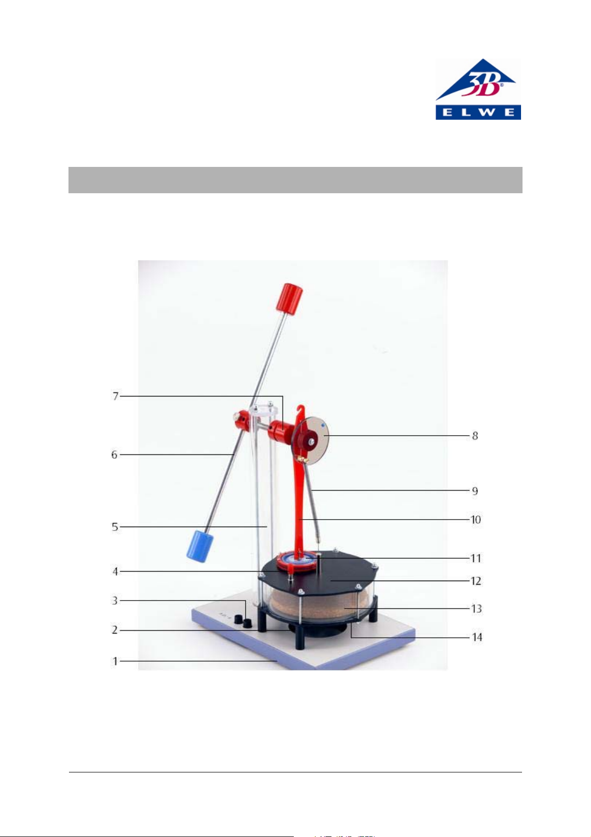
1 Base plate
2 Hole for tea candle
3 Hot plate connector
4 Hose nozzle with sealing cap
5 Stand
6 Rotor with weights
7 Eccentric with groove
8 Torque disc
9 Tension spring
10 Connector rod with hook
11 Working piston (membrane)
12 Upper plate
13 Displacement piston
14 Lower plate with electric heater
1
Page 2

1. Safety instructions
When working with naked flames, there is always a
risk of fire and injury.
• Take extra care when handling naked flames
and molten wax.
• The Stirling engine may not be heated electri-
cally at the same time as it is being heated by a
candle. There is a risk of damage to the
equipment.
• When operating the Stirling engine using a
spotlight or sunlight, it is essential that care be
taken not to expose the red plastic components
to intense heat.
2. Description
The Stirling engine D is a fully functional model,
optimised for teaching purposes and intended to
demonstrate how thermal energy can be converted
to mechanical energy as well as for investigating
the Stirling cycle.
The displacement piston moves discontinuously
with a delay during heating and cooling of the
working medium, air. This emulates the ideal Stirling cycle better than would be the case with a
continuously moving piston and also makes for
improved efficiency. The motion of the displacement piston is controlled by the torque disc. When
heat is supplied from below, either by means of the
electric heater or by a candle flame, the displacement piston precedes the working piston (membrane) by about 100°. The optimum angle is technically dependent on the speed of rotation.
Heat can be supplied either by the built-in electric
hot plate, a candle or by focussed heat radiation
from the sun or by a lamp. The direction of rotation depends on whether the heat is supplied from
above or below.
To record pV diagrams, the pressure in the working
cylinder can be measured by means of a hose attached to the nozzle provided and the volume can
be determined by attaching a thread to the hook
on the connecting rod in order to measure the
stroke of the working piston.
3. Scope of delivery
1 D-series Stirling engine U8450450
1 Set of transport packaging (foam plastic block,
rubber band and retaining rod)
4. Accessories
Supplementary set for Stirling engine D U8440455
The supplementary set for the Stirling engine D
provides accessories necessary for constructing
sensors. The set consists of the following:
1 Base plate for assembly of displacement sensor
(U11371)
1 Knurled screw for attaching the base plate to the
stand
1 Stem with a magnetic base for the displacement
sensor
1 Silicone tube for attaching a relative pressure
sensor, ±100 hPa (U11321)
1 Set of threads with suction cup
2 Weights with hook, both 20 g
5. Technical data
Heater voltage: 8 – 15 V, 1.5 A
Gas volume: 330 cm³ – 345 cm³
Speed: 30 – 100 rpm
Dimensions
not including rotor: 260×185×330 mm
3
Rotor: 400 mm
Weight: 2.2 kg
2
Page 3

6. Operating principle
The principle of a how a Stirling engine works can
be divided, in simplified form, into the following
four processes:
Heating:
During the heating phase, the displacement piston (P1)
moves upwards so that air is displaced down into the
heated part of the displacement cylinder. Temperature
and pressure both rise in a fashion that is almost isochoric. The working piston is in its lower rest position
(bottom dead centre) at this point (see Fig. 1). The displacement piston moves in advance of the working
piston till it reaches its top dead centre position. This is
the point where the air is at its lowest volume, but
highest temperature and pressure (see Fig. 2).
Expansion:
The heated air expands almost isothermally, thus
P
forcing the working piston (P2) upwards. In the
process, mechanical work is transferred via the shaft
to the rotor. The volume of air increases as the air
absorbs heat and the pressure reduces (see Fig. 3).
Cooling:
Cooling occurs while the working piston is at top
dead centre and the displacement piston (P1) is on
its downstroke, forcing air to move into the upper
part of the displacement cylinder. The air then
cools and the upper plate absorbs heat. The displacement piston finally reaches bottom dead
centre (see Figs. 4 and 5).
Compression:
The cooler air is compressed isothermally by the
working piston moving downwards. The mechanical work needed for this is supplied by the rotor
acting as a flywheel (see Fig. 6).
P
P1
Fig. 1 Heating
Fig. 2 Heating
P1
V
P
V
P
Fig. 4 Cooling
Fig. 5 Cooling
P
P
P2
Fig. 3 Expansion
P2
V
Fig. 6 Compression
3
Page 4

7. Getting the engine ready for use
• Connect the power supply to the pair of sockets
and set the heater voltage up to 12 V (1.5 A
approx.).
• After heating for about one or two minutes,
start the engine by pushing the rotor clockwise
as seen from the front of the engine.
• If the Stirling engine fails to keep moving of its
own accord, wait about a minute longer and
push the rotor round again.
The speed of the engine is nearly proportional to
the difference in temperature between the top
plate and the bottom plate and is thus largely dependent on the heat supplied.
• Reduce the heater voltage in steps down to
about 8 V and observe how the speed reduces.
8.1.2 Heating via a candle flame
• Light a tea candle and place it on a heat-
resistant mat.
• Place the Stirling engine over the candle so the
Fig. 7 Stirling engine as secured for storage
• Remove the rubber band (3) from the securing
hook (4) for the displacement piston and take
the hook out of the hose nozzle.
• Seal off the hose nozzle with the red cap (5).
• Remove the foam plastic block (2) between the
stand and the rotor weight.
• Undo the securing screw (1), align the rotor
horizontally so that it is balanced and tighten
the screw back up again.
The engine is then ready for use.
The Stirling engine must not be transported unless
the displacement piston is secured.
• To secure it, take the sealing cap of the hose
nozzle, put the securing hook back in and secure it in place with the rubber band.
• Secure the rotor as well.
8. Operation
8.1 Operation as a heat engine
8.1.1 Electric heating
The following power supplies are recommended for
heating the Stirling engine electrically:
1 DC power supply, 15 V, 1.5 A (230 V, 50/60 Hz)
U8521121-230
or
1 DC power supply, 15 V, 1.5 A (115 V, 50/60 Hz)
U8521121-115
hole in the middle is over the flame.
• Wait for several minutes until the lower plate
has heated up.
• Push the rotor clockwise as seen from the front
of the engine.
• If the Stirling engine fails to keep moving of its
own accord, wait about a minute longer and
push the rotor round again.
8.1.3 Heating via a lamp (spotlight)
• Shine a light on the top plate from about 1 or 2
cm using a lamp with a 60-W bulb and a focussed beam (spotlight). In this case it is the lower
plate that will cool the air in the displacement
cylinder.
• Alternatively, the upper plate can be heated
via sunlight focused using a concave mirror.
• Wait for about 8 to 10 minutes until the upper
plate has heated up.
• Push the rotor anti-clockwise as seen from the
front of the engine.
• If the Stirling engine fails to keep moving of its
own accord, wait about a minute longer and
push the rotor round again.
8.2 Recording a pV diagram
To record a pV diagram, the following pieces of
equipment are also required:
1 Supplementary set for Stirling engine D U8440455
1 3B NETlog™ unit (230 V, 50/60 Hz) U11300-230
or
1 3B NETlog™ unit (115 V, 50/60 Hz) U11300-115
4
Page 5

1 3B NETlab™ program U11310
1 Relative pressure sensor, ±100 hPa U11321
This load ensures that the pV diagram comes out
better.
1 Displacement sensor U11371
1 DC power supply, 15 V, 1.5 A (230 V, 50/60 Hz)
U8521121-230
or
1 DC power supply, 15 V, 1.5 A (115 V, 50/60 Hz)
U8521121-115
• Connect the relative pressure sensor to the
hose nozzle using silicone tubing.
• Attach the base plate to the stand using the
knurled screw.
• Screw the stem with the magnetic base into the
displacement sensor and place it on the base
plate.
• Loosen the screw on the displacement sensor’s
pulley. Wind a thread once around the pulley
and lead it out of the recess placing a loop
around the screw. Use the screw to fix the
thread in place (see Fig. 8).
• Attach one end of the thread to the hook of the
connector rod and suspend a weight from the
other end.
• Use the suction pad to attach a second thread
to the base plate. Thread this over the groove
in the eccentric and use the other weight as a
load on the free end.
Fig. 8 Schematic illustration of how the thread is wound
around the pulley of the displacement sensor (U11371)
• Connect the power supply to the heater plate
and set the voltage up to 12 V (1.5 A approx.).
• Connect both sensors to the 3B NETlog™ inter-
face.
• Run the software on a computer.
• After the Stirling engine has heated up, start it
running by pushing the rotor in a clockwise direction.
• Start a measurement using the software and
evaluate the data.
Fig. 9 Experiment set-up for recording a pV diagram
5
Page 6

Fig. 10 Pressure-volume diagram for D-series Stirling engine
Elwe Didactic GmbH • Steinfelsstr. 5 • 08248 Klingenthal • Germany • www.elwedidactic.com
3B Scientific GmbH • Rudorffweg 8 • 21031 Hamburg • Germany • www.3bscientific.com
Subject to technical amendments
© Copyright 2010 3B Scientific GmbH
 Loading...