

Page 1

3B SCIENTIFIC3B SCIENTIFIC
3B SCIENTIFIC®
3B SCIENTIFIC3B SCIENTIFIC
Dampfmaschine, transparent U10055
Bedienungsanleitung
07/05 ALF
bp
bq
br
bs
bt
bu
PHYSICSPHYSICS
PHYSICS
PHYSICSPHYSICS
1
23
4
1 Kondensatschlauch
2 Abdampfschlauch
789blbmbnbo
3 Abflussschlauch
4 Feder
5 Schwungrad
6 Kurbelwelle
7 Pleuel
8 Arbeitszylinder
9 Arbeitskolben
bl Zylinderwange
bm Träger
bn Zudampfschlauch
bo Sicherheitsventil
bp Kesselverschluss
bq Kessel
br Abdampfrohr
5
6
bs Grundplatte
bt Spiritusbrenner
bu Kondensatbecher
Die Dampfmaschine dient zur Demonstration der Funktionsweise einer oszillierenden Dampfmaschine.
Sicherheitsnormen Dampfmaschinen allgemein Bezogen auf Dampfmaschine U10055
1. Keine scharfen Ecken und Kanten
2. Schutz gegen Korrosion 2. Es wurden keine korrosionsanfälligen Werkstoffe ver-
3. Temperaturbegrenzung bei Bedienungselementen 3. Der Docht des Spiritusbrenners ist verstellbar.
4. Bei der Dampfmaschine darf der Kesselinhalt
2000 ccm und der Betriebsdruck 1,5 bar Überdruck
nicht überschreiten.
• Für Dampfmaschinen gelten die Sicherheitsnormen
nach DIN 31000:1979-03.
1. Es sind keine scharfen Ecken und Kanten vorhanden.
wendet.
4. Der Kesselinhalt beträgt 50 ccm. Der Betriebsdruck
beträgt 0,5 bar.
1
1. Sicherheitshinweise
Page 2

Sicherheitsnormen Dampfmaschinen allgemein Bezogen auf Dampfmaschine U10055
5. Ein unverstellbares Federsicherheitsventil aus nicht
rostendem Material, wobei der Ansprechdruck unter
max. 3,0 bar (2-facher Betriebsdruck) liegen muss.
6. Der Berstdruck des Kessels beträgt wenigstens den
3-fachen Betriebsdruck.
7. Der Wasserstand muss möglichst als Schauglas angezeigt werden.
8. Eine leicht verständliche Gebrauchsanleitung und die
Kennzeichnung mit Namen oder Zeichen des Herstellers ist vorgeschrieben.
• Dampfmaschine nur in Betrieb nehmen, wenn sich
alle Bauteile in einem einwandfreien Zustand befinden und deren Funktionstüchtigkeit gewährleistet ist.
Insbesondere ist darauf zu achten, dass sich im gläsernen Kessel bq kein Riss befindet oder er nicht
anderweitig beschädigt ist.
• Ausschließlich destilliertes Wasser, entmineralisiert
nach VDE 0510, verwenden. Bei Gebrauch herkömmlichen Leitungswassers ist durch entsprechende Ablagerungen an sicherheitsrelevanten Bauteilen deren
Funktionsfähigkeit nicht mehr gewährleistet.
• Brennspiritus vorsichtig in Spiritusbrenner bt ein-
füllen, darauf achten, dass nichts verschüttet wird.
• Spiritusbrenner nie befüllen, solange der Docht noch
glimmt oder eine andere offene Flamme in der Nähe
ist.
• Spiritusflasche nach Gebrauch sofort verschließen.
• Nicht in die offene Flamme fassen.
• Vorsicht! Flamme des Spiritusbrenners nur mit dem
befestigten Deckel löschen. Die Flamme nicht in der
Nähe des Kessels ausblasen, da ein plötzlicher Temperaturwechsel zum Bruch des gläsernen Kessels
führen kann.
• Die Beheizung des Kessels ist nicht zulässig, wenn er
nicht mit Wasser gefüllt ist. Daher ist die Flamme des
Spiritusbrenners rechtzeitig zu löschen.
• Während und nach dem Betrieb der Dampfmaschine
Dampf führende Bauteile insbesondere Kessel bq,
Schläuche 1, 2, 3, bn, Abdampfrohr br,
Träger bm und auch Spiritusbrenner bt nicht berühren. Verbrennungsgefahr!
• Dampfmaschine vor dem Wegräumen abkühlen las-
sen.
2. Beschreibung, technische Daten
Die oszillierende Dampfmaschine wurde für den Einsatz
als Lehrmittel konzipiert. Um die einzelnen Bewegungsabläufe jederzeit beobachten zu können, wurde bei der
Konstruktion insbesondere Wert auf Transparenz gelegt.
Daher bestehen Arbeitszylinder 8 und Kessel bq aus
hitzebeständigem Spezialglas sowie das Schwungrad 5
5. Ein unverstellbares Federsicherheitsventil aus nicht
rostendem Material ist vorhanden, wobei der Ansprechdruck 1,0 bar (2-facher Betriebsdruck) beträgt.
6. Der Berstdruck des Kessels beträgt wenigstens 1,5 bar
(mind. 3-facher Betriebsdruck). Jeder Kessel wird durch
eine Berstdruckprüfung (2 bar+) auf seine Sicherheit
und Dichtheit kontrolliert.
7. Der Wasserstand wird jederzeit durch den gläsernen
Kessel angezeigt.
8. Eine Gebrauchsanweisung wird mit jedem Gerät geliefert. Auf der Grundplatte befindet sich ein entsprechender Siebdruck.
aus Acryl-Glas. Die gehärtete Kurbelwelle 6 und das
Pleuel 7 sind kugelgelagert. Der aus Graphit gefertigte
Arbeitskolben 9 läuft im Arbeitszylinder trocken - ohne
zusätzliche Schmierung. Deshalb arbeitet die Dampfmaschine sehr leise und dauerlauffest mit einer Leistung
von ca. 1 W mechanisch. Das Sicherheitsventil bo befindet sich im Kesselverschluss bp. Es öffnet sich, sobald
der Druck im Kessel 1,0 bar überschreitet. Unabhängig
hiervon verfügt die Maschine über eine zweite Überdrucksicherung. Bis zu einem Überdruck von ca. 1,5 bar wird
der Wasserdampf in die Kanäle des Trägers bm gepresst
und über den Kondensatschlauch 1 abgeführt. Bei
einem Druck über 1,5 bar wird die Zylinderwange bl
durch Nachgeben der Feder 4 vom Träger weggedrückt,
so dass der Wasserdampf ungehindert aus dem Dampfeinlassloch des Trägers strömen kann.
Kolbendurchmesser: 19 mm
Kolbenhub: 10 mm
Kesseldurchmesser: 50 mm
Kesselvolumen 50 ml
Laufzeit je Füllung: ca. 20 – 25 min
Drehzahl 800 U/min.
Mech. Leistung ca. 1 W
Betriebsdruck max. 0,5 bar
Ansprechdruck Sicherheitsventil: 1,0 bar
Berstdruckprüfung des Kessels min.: 2,0 bar
3. Funktionsprinzip
Im Gegensatz zu einer schiebergesteuerten Dampfmaschine bewegt sich der Zylinder bei einer oszillierenden
Dampfmaschine um eine Mittelachse und öffnet bzw.
schließt während seiner Bewegung den Ein- und Auslass
der Dampfkanäle.
Im Kessel wird das Wasser erhitzt und Wasserdampf erzeugt. Der Wasserdampf strömt über den Zudampfschlauch bn in den Träger zum Dampfeinlassloch. Sobald sich die Öffnung des Zylinders und die Frischdampfzuführung begegnen, strömt Dampf in den Zylinder und
verdrängt den Kolben (Fig. 1 a). Wenn der Kolben in der
untersten Stellung angekommen ist, sind die Dampfka-
2
Page 3
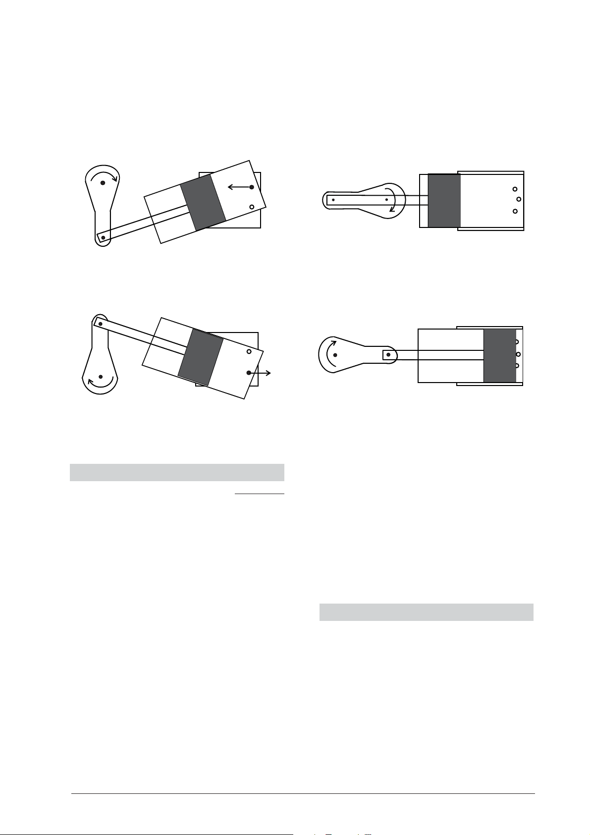
näle geschlossen. Mit Hilfe des Schwungrads wird dieser
Totpunkt überwunden (Fig. 1 b). In der nächsten Phase
bewegt sich der Kolben zurück, öffnet das Dampfauslassloch und drückt den Dampf hinaus (Fig. 1 c). Der
Dampf wird über den Abdampfschlauch 2 und das
Abdampfrohr br abgeführt. Angefallenes Kondensat wird
ab
über den Kondensatschlauch 1 in den Kondensatbecher bu abgeleitet. Der Kolben erreicht den oberen Totpunkt, bei dem wieder beide Dampfkanäle geschlossen
sind. Nach Überwindung des oberen Totpunktes mittels
des Schwungrads wird wieder Dampf zugeführt und der
Prozess beginnt erneut (Fig. 1 d).
Fig.1: Arbeitszyklus der oszillierenden Dampfmaschine
4. Bedienung
• Füllschraube bp öffnen und Kessel mit destilliertem
Wasser (entmineralisiert nach VDE 0510) befüllen. Den
Kessel nicht vollständig bis zum Kesseldeckel füllen
sondern ca. 5 mm Luftsäule beibehalten. Die Dampfmaschine funktioniert ebenso gut bei nur halb gefülltem Kessel. Lediglich das Betriebsintervall verringert sich entsprechend.
• Docht des Spiritusbrenners entzünden und Kessel
beheizen.
• Dampfeinlassloch zum zügigeren Druckaufbau schlie-
ßen.
• Nach ca. zwei Minuten beginnt das Wasser im Kessel
zu sieden. Von nun an werden noch weitere ca. 2 – 3
Minuten benötigt, um den notwendigen Betriebsdruck aufzubauen. Wasserdampf strömt über den
Zudampfschlauch in den Träger zum Dampfeinlassloch. Überschüssiges Kondensat wird über den Abflussschlauch 3 in den Kondensatbecher abgeleitet. Hierzu wurden Kanäle in den Träger gefräst, in
denen das Kondensat gesammelt und abgeleitet wird.
• Die Maschine kann nun durch Drehung des Schwung-
rades im Uhrzeigersinn (bei Blick auf den Arbeitszylinder) in Betrieb genommen werden.
• Die Leistung der Maschine nimmt ab, wenn nicht
mehr genügend Wasser im Kessel vorhanden ist. Die
dc
Beheizung des Kessels ist nicht zulässig, wenn er nicht
mit Wasser gefüllt ist. Daher ist die Flamme des Spiritusbrenners rechtzeitig zu löschen.
• Die Flamme des Spiritusbrenners nicht in der Nähe
des Kessels ausblasen, sondern mit dem befestigten
Deckel löschen.
• Während des Abkühlungsprozesses wird das Konden-
sat aus dem Kondensatbecher über Kondensatschlauch, Träger und Zudampfschlauch in den Kessel
gesogen.
5. Aufbewahrung und Reinigung
• Dampfmaschine staubfrei lagern.
• Zur Reinigung der Dampfmaschine feuchtes Tuch ggf.
mit etwas Spülmittel verwenden. Acrylglasteile nie
mit Lösungsmitteln oder aggressiven Putzmitteln reinigen.
• Nach häufiger Inbetriebnahme kann sich durch steti-
ge Flammeneinwirkung an der Unterseite des Kessels bq eine Rußschicht ablagern. Diese lässt sich je-
doch mit einem in Aceton getränkten Lappen lösen
und entfernen.
• Nach der Reinigung gut abtrocknen, um Wasserflecke
zu vermeiden.
3B Scientific GmbH • Rudorffweg 8 • 21031 Hamburg • Deutschland • www.3bscientific.com • Technische Änderungen vorbehalten
3
Page 4

3B SCIENTIFIC3B SCIENTIFIC
3B SCIENTIFIC®
3B SCIENTIFIC3B SCIENTIFIC
Steam engine, transparent U10055
Instruction Sheet
07/05 ALF
bp
bq
br
bs
bt
bu
PHYSICSPHYSICS
PHYSICS
PHYSICSPHYSICS
1
23
4
1 Condensation hose
2 Exhaust steam hose
789blbmbnbo
3 Drainage hose
4 Spring
5 Flywheel
6 Crankshaft
7 Connecting rod
8 Main cylinder
9 Main piston
bl Cylinder flank
bm Support frame
bn Steam feeding hose
bo Safety valve
bp Boiler cap
bq Boiler
br Exhaust steam pipe
5
6
bs Base plate
bt Spirit burner
bu Condensation beaker
The steam engine is used to demonstrate how an oscillating steam engine functions.
General safety standards applicable to steam engines Specific conformance of steam engine U10055
1. No sharp corners or edges
2. Protection against corrosion 2. No materials that are subject to corrosion have been
3. Temperature limiting for operating elements 3. The wick of the spirit burner can be adjusted.
4. The boiler capacity of the steam engine may not
exceed 2000 cc Maximum operating pressure may not
exceed 1.5 bars.
• The safety standards applicable to the steam engine
are specified in DIN 31000:1979-03.
1. There are no sharp corners or edges on this device.
used.
4. The boiler capacity is 50 cc. The operating pressure is
0.5 bars.
4
1. Safety instructions
Page 5

General safety standards applicable to steam engines
Specific conformance of steam engine U10055
5. An adjustable spring-operated safety valve made of
non-rusting material with a safety threshold of no
more than 3.0 bars (double the operating pressure)
must be provided.
6. The bursting pressure of the boiler should be no less
than 3-times the operating pressure.
7. The water level must be visible, if possible, with the
aid of an inspection window.
8. An easy to understand instruction sheet is required
plus a label with the name or logo of the manufacturer.
• Only put the steam engine into operation if all of the
components are in perfect condition and their functionality is assured. Special attention must be made
to ensure that there are no cracks or any other damage to the glass boiler bq.
• Only use distilled water that has been demineralised
as per VDE 0510. If conventional tap water is used the
associated deposits that form on the safety-relevant
components mean that functionality can no longer
be guaranteed.
• Carefully pour alcohol into the burner bt. Make sure
that nothing spills.
• Never pour in alcohol while the wick is still glowing or
if there is any other open flame in the immediate
proximity.
• Seal the bottle of alcohol immediately after use.
• Keep away from the open flame. Be careful! Only ex-
tinguish the burner flame by means of the attached
cover. Do not blow on the flame in the proximity of
the boiler, as any sudden temperature change could
cause the boiler to crack.
• The boiler may not be heated unless it is filled with
water. For that reason it is important to extinguish
the lamp’s flame before it boils dry.
• Do not touch any components steam carrying, par-
ticularly the boiler bq, hoses 1, 2, 3, bn, steam
exhaust pipe br and support frame bm. Do not
touch the spirit burner bt during or after operating
the steam engine either. Risk of burns!
• Let the steam engine cool before storing.
2. Description, technical data
The oscillating steam engine has been designed for use
in a training and educational environment. In order that
individual operations and dynamic processes should be
observable, particular emphasis has been placed on transparent construction. For that reason the main cylinder
8 and boiler bq are made of heat-resistant special glass
and the flywheel 5 is made of acrylic. The hardened
crankshaft 6 and the connecting rod 7 are ball-bear-
ing mounted. The graphite piston 9 runs dry in the
5. This unit is equipped with an adjustable spring-operated safety valve made of non-rusting material with
a safety threshold of 1.0 bar (double the operating
pressure)
6. The boiler’s bursting pressure is at least 1.5 bars (at
least three times the operating pressure). Each boiler
is checked for safety and leaks by means of a burst
pressure test (2 bars+).
7. The water level is visible at all times because of the glass
boiler.
8. An instruction sheet is supplied with each apparatus.
An appropriate silk-screen printed label is located on
the base plate.
operating cylinder – i.e. without any added lubricant. For
that reason the steam engine runs very quietly and safely for long periods, providing a mechanical power output of approx. 1 W. The safety valve bo is located in the
boiler cap bp. It opens as soon as the boiler pressure
exceeds 1.0 bar. In addition, the machine is also equipped
with a second, independent excess pressure safety mechanism. Up to a pressure of approx. 1.5 bars the steam is
forced into the ducts of the support frame bm and discharged via the condensation hose 1. When the pressure exceeds 1.5 bars the cylinder flank bl is forced away
from the frame because the tension in the spring 4 is
overcome so that the steam can flow unimpeded out of
the steam inlet hole in the frame.
Piston diameter: 19 mm
Piston stroke: 10 mm
Boiler diameter: 50 mm
Boiler volume: 50 ml
Operating time per filling: approx. 20-25 mins
Speed: 800 rpm
Mech. Power output: approx. 1 W
Max. operating pressure: 0.5 bars
Trigger pressure
of the safety valve: 1.0 bars
Minimum boiler
bursting pressure test: 2.0 bars
3. How the apparatus works
Unlike a slide-valve steam-engine, an oscillating steam
engine has a cylinder that rotates on a central shaft causing steam inlet and outlet ducts to open and close. Water
in the boiler begins to boil, and thus steam is generated.
The steam flows via the steam inlet hose bn into the
frame then through the steam inlet hole. As soon the
opening of the cylinder is fed with fresh steam, steam
flows into the cylinder and displaces the piston (Fig. 1, a).
When the piston reaches its lowest point, the steam ducts
are closed. This slack point is passed thanks to the inertia
of a flywheel (Fig 1, b). In the next phase, the piston moves
back, opens the steam outlet and pushes out the steam
5
Page 6

(Fig. 1, c). The steam flows out via the exhaust steam
hose 2 and the exhaust steam pipe br. The condensed
water that accumulates drips out via the condensation
hose 1 into the condensation beaker bu.
ab
When the piston has reached the dead point at the top,
both of the steam ducts are closed again. The flywheel
drags the engine past this top slack point, after which
steam is once again fed in and the procedure repeats
from the start (Fig. 1, d).
Fig. 1: Work cycle of an oscillating steam engine
4. Operation
• Open the boiler cap bp and fill up the boiler with
distilled water (demineralised water conforming to
VDE 0510). Do not fill up the boiler to the brim, maintain an air column of approx. 5 mm. The steam engine functions equally well even if the boiler is only
half-filled. Only the operating duration is correspondingly reduced.
• Light the wick of the spirit burner and heat the boiler.
• Shut the steam inlet opening to enable quicker build
up of pressure.
• After approx. 2 minutes, the water in the boiler be-
gins to boil. From this point onwards, only approx.
2-3 minutes are needed to attain the required operating pressure. Steam flows via the steam feeding
hose into the steam inlet opening. Excess condensed
water drips into the condensate beaker via the drainage hose 3. For this purpose, channels that facilitate collection and transfer of the condensed water
are milled into the frame.
• The engine can now be operated by turning the fly-
wheel in a clockwise direction (while observing the
main cylinder).
dc
• The power of the engine decreases if there is not
enough water left in the boiler. It is not permitted to
heat the boiler if it is not filled with water. The spirit
burner should, therefore, be extinguished at the appropriate time.
• Do not blow out the flame in the proximity of the
boiler. Use the attached cap to extinguish the flame.
• During the cooling process, condensed water is sucked
up from the condensation beaker via the condensation hose, frame and steam feeding hose and transferred into the boiler.
5. Storage and maintenance
• Store the steam engine in a dust-free place.
• To clean use a damp cloth, if necessary, with some
washing-up liquid. Never use solvents or aggressive
cleaning agents to clean the acrylic glass components.
• Frequent use of the apparatus may cause a layer of
soot to deposit on the underside of the boiler bq due
to the constant play of a flame. This, however, can be
dissolved and removed by using a cloth soaked in
acetone.
• In order to prevent water stains appearing, dry thor-
oughly after cleaning.
3B Scientific GmbH • Rudorffweg 8 • 21031 Hamburg • Germany • www.3bscientific.com • Technical amendments are possible
6
Page 7

3B SCIENTIFIC3B SCIENTIFIC
3B SCIENTIFIC®
3B SCIENTIFIC3B SCIENTIFIC
Machine à vapeur transparente U10055
Manuel d’utilisation
07/05 ALF
PHYSICSPHYSICS
PHYSICS
PHYSICSPHYSICS
789blbmbnbo
1 Tuyau d’eau de conden-
sation
2 Tuyau de vapeur
3 Tuyau d’écoulement
4 Ressort
5 Roue volante
bp
bq
br
bs
bt
bu
1
23
La machine à vapeur permet de démontrer le fonctionnement d’une machine à vapeur oscillante.
4
6 Manivelle
7 Bielle
8 Cylindre de travail
9 Piston de travail
bl Paroi de cylindre
bm Support
bn Tuyau d’amenée de va-
peur
bo Soupape de sécurité
bp Fermeture de chaudière
bq Chaudière
br Tube d’évacuation de
vapeur
bs Plaque de base
5
6
bt Brûleur
bu Gobelet d’eau de con-
densation
1. Consignes de sécurité
• Les machines à vapeur sont soumises aux normes de
sécurité selon DIN 31000:1979-03.
Normes de sécurité machines à vapeur en général Relatives à la machine à vapeur U10055
1. Pas de coins ni arêtes tranchants
2. Protection contre la corrosion 2. Aucun matériau sensible à la corrosion n’a été utilisé.
3. Limitation de température pour les éléments de
manipulation
4. Le volume de la chaudière ne doit pas dépasser 2 000
cm³ et la pression de service une surpression de 1,5
bar.
1. Il n’y a pas de coins ni arêtes tranchants.
3. La mèche du brûleur peut être ajustée
4. La chaudière offre une capacité de 50 cm³. La pression de service s’élève à 0,5 bar.
7
Page 8

Normes de sécurité machines à vapeur en général
Relatives à la machine à vapeur U10055
5. Soupape de sécurité non ajustable à ressort en matériau inox, la pression de réponse ne devant pas être
inférieure à max. 3,0 bars (double pression de service).
6. La pression d’éclatement de la chaudière doit s’élever à au moins trois fois la pression de service.
7. Dans la mesure du possible, le niveau d’eau doit être
affiché à l’aide d’un verre-regard.
8. Un manuel d’utilisation aisément compréhensible et
une identification avec nom ou sigle du constructeur
sont indispensables.
• Ne mettre la machine à vapeur en marche que si tous
les composants sont en parfait état et que leur fonctionnement est garanti. Veiller notamment à ce que
la chaudière en verre bq ne présente aucune fissure
ni aucun autre endommagement.
• Utiliser uniquement de l’eau distillée, déminéralisée
selon VDE 0510. L’emploi d’eau du robinet normale
entraîne des dépôts sur les composants importants
pour la sécurité et ne peut donc plus garantir le parfait fonctionnement de ces derniers.
• Remplir avec précaution l’alcool dénaturé dans le
brûleur bt, en veillant à ne rien renverser.
• Ne jamais remplir le brûleur lorsque la mèche est
encore rouge ou en cas de présence d’une flamme
nue à proximité.
• Refermer le flacon d’alcool dénaturé immédiatement
après son emploi.
• Ne jamais toucher la flamme nue.
• Prudence ! Eteindre la flamme du brûleur unique-
ment avec le couvercle qui y est fixé. Ne pas souffler
la flamme à proximité de la chaudière, car un brusque changement de température peut provoquer la
cassure de la chaudière en verre.
• Si elle n’est pas remplie d’eau, il est interdit de chauf-
fer la chaudière. Aussi la flamme du brûleur doit-elle
être éteinte à temps.
• Pendant et après l’exploitation de la machine à va-
peur, ne pas toucher les composants entrant en contact avec la vapeur, comme notamment la chaudière
bq, les tuyaux 1, 2, 3, bn, le tube d’évacuation
de vapeur br, le support bm et le brûleur bt. Risque
de brûlure !
• Avant de la ranger, laisser la machine à vapeur refroi-
dir.
5. La machine présente une soupape de sécurité non
ajustable à ressort en matériau inox, la pression de
réponse s’élevant à 1,0 bar (double pression de service).
6. La pression d’éclatement de la chaudière s’élève à au
moins 1,5 bar (au moins trois fois la pression de service). La sécurité et l’étanchéité de chaque chaudière
sont surveillées par un dispositif de contrôle de pression d’éclatement (2 bars+).
7. Le niveau d’eau est visible à tout moment à travers la
chaudière transparente.
8. Un manuel d’utilisation est livré avec chaque appareil.
Une plaquette sérigraphiée est appliquée sur la plaque
de base.
8 et la chaudière bq sont-ils en verre spécial résistant
aux températures élevées et la roue volante 5 en verre
acrylique. La manivelle durcie 6 et la bielle 7 sont
montées sur un roulement à billes. Le piston en graphite
9 marche à sec dans le cylindre - sans lubrification sup-
plémentaire. Aussi, conçue pour une exploitation permanente, la machine à vapeur est-elle particulièrement
silencieuse et offre une puissance d’env. 1 W mécanique.
La soupape de sécurité bo se trouve dans la fermeture
de la chaudière bp. Elle s’ouvre dès que la pression dans
la chaudière dépasse 1,0 bar. Indépendamment de cela,
la machine dispose d’un second mécanisme de sûreté.
En cas de surpression d’env. 1,5 bar, la vapeur d’eau est
pressée dans les canaux du support bm et évacuée par le
tuyau d’eau de condensation 1. Lorsque la pression
atteint 1,5 bar, la paroi de cylindre bl est dégagée du
support par le relâchement du ressort 4, de sorte que
la vapeur d’eau puisse être dégagée sans obstacle par
l’orifice d’alimentation de vapeur du support.
Diamètre de piston : 19 mm
Course de piston : 10 mm
Diamètre de chaudière : 50 mm
Volume de chaudière : 50 ml
Durée par remplissage : env. 20 – 25 min
Vitesse de rotation : 800 t/min
Puissance mécan. : env. 1 W
Pression de service max. : 0,5 bar
Pression de réponse
soupape de sécurité : 1,0 bar
Contrôle de pression
d’éclatement de
la chaudière, min. : 2,0 bars
2. Description, caractéristiques techniques
La machine à vapeur oscillante a été conçue pour l’enseignement. Pour permettre d’observer à tout moment
chaque mouvement, nous avons attaché une grande
importance à la transparence. Aussi le cylindre de travail
3. Principe du fonctionnement
Contrairement à une machine à vapeur à coulisse, le cylindre d’une machine à vapeur oscillante tourne autour
d’un axe central. Son mouvement ouvre et ferme l’entrée et la sortie des canaux de vapeur.
8
Page 9

Dans la chaudière, l’eau est réchauffée et de la vapeur se
forme. La vapeur traverse le tuyau d’alimentation bn
dans le support pour accéder à l’orifice d’entrée de vapeur. Dès que l’ouverture du cylindre rencontre l’alimentation de vapeur fraîche, de la vapeur pénètre dans le
cylindre et repousse le piston (Fig. 1 a). Lorsque le piston
atteint sa position inférieure finale, les canaux de vapeur
se referment. La roue volante permet de surmonter ce
ab
point mort (Fig. 1 b). Au cours de la phase suivante, le
piston revient en arrière, ouvre l’orifice de sortie de vapeur et refoule la vapeur (Fig. 1 c). La vapeur est évacuée
à travers le tuyau 2 et le tube br. L’eau de condensation est évacuée dans le gobelet bu à travers le tuyau 1.
Le piston atteint le point mort supérieur, les deux canaux
de vapeur sont de nouveau fermés. La roue volante ayant
surmonté le point mort supérieur, de la vapeur est de
nouveau introduite et le processus recommence (Fig. 1 d).
Fig.1 : Cycle de travail de la machine à vapeur oscillante
4. Manipulation
• Ouvrir la vis de remplissage bp et remplir la chaudiè-
re avec de l’eau distillée (déminéralisée selon VDE
0510). Ne pas remplir complètement la chaudière jusqu’au couvercle, mais garder une colonne d’air d’env.
5 mm. La machine à vapeur fonctionne tout aussi
bien lorsque la chaudière n’est remplie qu’à moitié.
Seule l’intervalle d’exploitation est réduit.
• Allumer la mèche du brûleur et réchauffer la chau-
dière.
• Refermer l’orifice d’entrée de vapeur pour que la pres-
sion augmente plus rapidement.
• Après environ deux minutes, l’eau dans la chaudière
commence à bouillir. Désormais, il faut encore deux
à trois minutes pour obtenir la pression de service
requise. De la vapeur traverse le tuyau d’alimentation dans le support pour accéder à l’orifice d’entrée
de vapeur. L’eau de condensation superflue est évacuée dans le gobelet à travers le tuyau d’écoulement
3. Des canaux ont été fraisés dans le support pour
recueillir et évacuer l’eau de condensation.
• A présent, on peut mettre la machine à vapeur en
route en tournant la roue dans le sens des aiguilles
d’une montre (vue sur le cylindre).
dc
• Si la quantité d’eau dans la chaudière est insuffisan-
te, la puissance de la machine diminue. Si elle n’est
pas remplie d’eau, il est interdit de chauffer la chaudière. Aussi la flamme du brûleur doit-elle être éteinte à temps.
• Ne pas souffler la flamme du brûleur à proximité de
la chaudière, mais à l’aide du couvercle.
• Pendant la phase de refroidissement, l’eau de con-
densation est aspirée depuis le gobelet dans la chaudière, via le tuyau d’eau de condensation, le support
et le tuyau d’alimentation de vapeur.
5. Nettoyage et rangement
• Ranger la machine à vapeur à l’abri de la poussière.
• Pour nettoyer la machine, utiliser un chiffon humide
avec éventuellement un peu de produit de rinçage.
Ne pas nettoyer les pièces en verre acrylique avec des
solvants ou des nettoyants agressifs.
• En cas d’emploi fréquent, la flamme peut entraîner
le dépôt d’une couche de suie sur la partie inférieure
de la chaudière bq. Pour l’essuyer, utiliser un chiffon
imbibé d’acétone.
• Après le nettoyage, bien sécher pour éviter des ta-
ches d’eau.
3B Scientific GmbH • Rudorffweg 8 • 21031 Hamburg • Allemagne • www.3bscientific.com • Sous réserve de modifications techniques
9
Page 10

3B SCIENTIFIC3B SCIENTIFIC
3B SCIENTIFIC®
3B SCIENTIFIC3B SCIENTIFIC
Macchina a vapore, trasparente U10055
Istruzioni per l’uso
07/05 ALF
bp
bq
br
bs
bt
bu
PHYSICSPHYSICS
PHYSICS
PHYSICSPHYSICS
1
23
4
1 Tubo della condensa
2 Tubo vapore di scarico
789blbmbnbo
3 Tubo di scarico
4 Molla
5 Volano
6 Albero a gomiti
7 Biella
8 Cilindro di lavoro
9 Pistone di lavoro
bl Spalla del cilindro
bm Supporto
bn Tubo vapore aggiuntivo
bo Valvola di sicurezza
bp Tappo caldaia
bq Caldaia
br Condotto vapore di
scarico
5
6
bs Piastra di base
bt Bruciatore ad alcool
bu Vaso della condensa
La macchina a vapore serve per dimostrare il funzionamento di una macchina a vapore oscillante.
Norme di sicurezza generali macchine a vapore Riferite alla macchina a vapore U10055
1. Assenza di angoli e bordi taglienti 1. Non sono presenti angoli e bordi taglienti.
2. Protezione contro la corrosione 2. Non sono stati utilizzati materiali soggetti a
3. Limitazione della temperatura degli elementi di comando
4. Nella macchina a vapore, il contenuto della caldaia
non deve superare i 2000 ccm e la pressione di esercizio non deve superare 1,5 bar di sovrapressione.
• Per le macchine a vapore si applicano le norme di
sicurezza conformi alla normativa DIN 31000:1979-03.
corrosione.
3. Lo stoppino del bruciatore ad alcool è
regolabile.
4. La capacità della caldaia è di 50 ccm. La pressione di
esercizio è pari a 0,5 bar.
10
1. Norme di sicurezza
Page 11

Norme di sicurezza generali macchine a vapore Riferite alla macchina a vapore U10055
5. La macchina deve essere dotata di una valvola di sicurezza a molla non regolabile in materiale inossidabile,
la cui pressione di intervento deve essere inferiore a
max. 3,0 bar (2 volte la pressione di esercizio).
6. La pressione di scoppio minima della caldaia deve essere pari al triplo della pressione di esercizio.
7. Il livello dell’acqua deve essere preferibilmente
indicato dal vetro spia.
8. La dotazione deve contenere un manuale di istruzioni
di facile comprensione e un contrassegno con nome o
simbolo del produttore.
• Mettere in funzione la macchina a vapore solo se
tutti i componenti sono in uno stato ottimale e la
capacità di funzionamento è garantita. In particolar
modo, assicurarsi che la caldaia di vetro bq non presenti crepe o non sia danneggiata in altro modo.
• Utilizzare esclusivamente acqua distillata, deminera-
lizzata secondo la norma VDE 0510. In caso di utilizzo
di acqua corrente tradizionale, il funzionamento di
componenti importanti per la sicurezza non è garantito a causa della formazione di depositi .
• Riempire con attenzione il bruciatore ad alcool bt
con alcool da ardere, facendo attenzione che non
fuoriesca.
• Non riempire il bruciatore ad alcool se lo stoppino
sta ancora bruciando o se nelle vicinanze è presente
un’altra fiamma aperta.
• Dopo l’uso chiudere immediatamente il flacone di
alcool.
• Non avvicinare le mani alla fiamma aperta.
• Attenzione! Spegnere la fiamma del bruciatore ad al-
cool solo con il coperchio fissato. Evitare di spegnere
la fiamma soffiandoci sopra nelle vicinanze della caldaia, poiché un’improvvisa variazione di temperatura può provocare la rottura della caldaia di vetro.
• Non riscaldare la caldaia in assenza di acqua. Spegne-
re in tempo la fiamma del bruciatore.
• Durante e dopo l’uso della macchina a vapore, non
toccare i componenti che contengono vapore, in particolar modo la caldaia bq, i tubi flessibili 1, 2, 3,
bn, il condotto del vapore di scarico br, il supporto
bm ed anche il bruciatore ad alcool bt. Pericolo di
ustioni!
• Lasciare raffreddare la macchina a vapore prima di
portarla via.
5. La macchina è dotata di una valvola di sicurezza a
molla non regolabile in materiale inossidabile, la cui
pressione di intervento è pari a 1,0 bar (2 volte la
pressione di esercizio).
6. La pressione di scoppio della caldaia è di almeno
1,5 bar (min. 3 volte la pressione di esercizio). Ogni
caldaia viene sottoposta al collaudo della pressione
di scoppio (2 bar+) per verificarne la sicurezza e la
tenuta.
7. Il livello dell’acqua può essere controllato in ogni
momento attraverso la caldaia di vetro.
8. Ogni apparecchio viene fornito con un manuale di
istruzioni. Sulla piastra di base è presente una stampa serigrafica corrispondente.
trasparenza. Pertanto, il cilindro di lavoro 8 e la caldaia
bq sono stati realizzati in vetro speciale resistente al calo-
re, così come il volano 5 realizzato in vetro acrilico.
L’albero a gomiti irrigidito 6 e la biella 7 sono dotati
di cuscinetti a sfere. Il pistone di lavoro in grafite 9
scorre a secco nel cilindro di lavoro e non necessita di
ulteriore lubrificazione. Pertanto, il funzionamento della
macchina a vapore è estremamente silenzioso e di lunga
durata ed è caratterizzato da una potenza meccanica di
ca. 1 W. La valvola di sicurezza bo è situata nel tappo
della caldaia bp. Si apre appena la pressione della caldaia
supera 1,0 bar. A prescindere da ciò, la macchina dispone
di un secondo dispositivo di sicurezza contro la sovrapressione. Fino ad una sovrapressione di ca. 1,5 bar, il
vapore acqueo viene compresso nei canali del supporto
bm e scaricato attraverso il tubo della condensa 1. Ad
una pressione superiore a 1,5 bar la spalla del cilindro bl
viene allontanata dal supporto mediante la distensione
della molla 4, in modo che il vapore acqueo possa defluire senza impedimenti dal foro di immissione del vapore del supporto.
Diametro pistone: 19 mm
Corsa: 10 mm
Diametro caldaia: 50 mm
Volume della caldaia: 50 ml
Durata a seconda
del riempimento: ca. 20 – 25 min
Numero di giri: 800 giri/min.
Potenza mecc.: ca. 1 W
Pressione di esercizio max.: 0,5 bar
Pressione di intervento
valvola di sicurezza: 1,0 bar
Collaudo pressione
di scoppio della caldaia min.: 2,0 bar
2. Descrizione, caratteristiche tecniche
La macchina a vapore oscillante è stata progettata per
essere utilizzata come sussidio didattico. Per poter osservare i singoli movimenti in qualsiasi momento, durante
la costruzione è stata data particolare importanza alla
3. Principio di funzionamento
Contrariamente ad una macchina a vapore con valvola a
cassetto, il cilindro di una macchina a vapore oscillante si
muove intorno ad un asse centrale e, durante il movi-
11
Page 12

mento, apre o chiude l’immissione e lo scarico dei canali
del vapore. Nella caldaia l’acqua si riscalda e genera vapore acqueo. Il vapore acqueo scorre attraverso il tubo
del vapore aggiuntivo bn del supporto fino al foro di
immissione del vapore. Non appena inizia l’apertura del
cilindro con l’alimentazione del vapore nuovo, il vapore
scorre nel cilindro e avvia la fase di compressione del
pistone (fig. 1 a). Quando il pistone raggiunge la posizione più in basso, i canali del vapore si chiudono. Con l’ausilio del volano questo punto morto viene superato
ab
(fig. 1 b). Nella fase successiva, il pistone compie il movimento di ritorno, apre il foro di scarico del vapore e spinge fuori il vapore (fig. 1 c). Il vapore viene scaricato attraverso il tubo del vapore di scarico 2 e il condotto del
vapore di scarico br. La condensa formatasi viene deviata dal tubo della condensa 1 nel vaso della condensa
bu. Il pistone raggiunge il punto morto superiore, in cor-
rispondenza del quale entrambi i canali del vapore sono
chiusi. Dopo il superamento del punto morto superiore
grazie al volano, l’alimentazione del vapore riprende e il
processo ricomincia (fig. 1 d).
Fig.1: Ciclo di lavoro della macchina a vapore oscillante
4. Utilizzo
• Aprire la vite di riempimento bp e riempire la caldaia
con acqua distillata (demineralizzata in conformità
con la norma VDE 0510). Non riempire la caldaia completamente fino al coperchio, ma lasciare una colonnina d’aria di ca. 5 mm. La macchina a vapore funziona ottimamente anche con la caldaia riempita per
metà. Solo l’intervallo di esercizio si riduce in maniera proporzionale.
• Accendere lo stoppino del bruciatore ad alcool e ri-
scaldare la caldaia.
• Chiudere il foro di immissione del vapore per ridurre
la pressione più rapidamente.
• Dopo ca. due minuti, l’acqua della caldaia comincia a
bollire. Da questo momento saranno necessari altri
2 – 3 minuti per raggiungere la pressione di esercizio
richiesta. Il vapore acqueo scorre attraverso il tubo
del vapore aggiuntivo del supporto fino al foro di
dc
immissione del vapore. La condensa in eccesso viene
deviata dal tubo di scarico nel vaso della condensa. A
tale scopo, nel supporto sono stati ricavati canali nei
quali la condensa si accumula e viene deviata.
• A questo punto la macchina può essere messa in
funzione ruotando il volano in senso orario (sguardo
rivolto verso il cilindro di lavoro).
• La potenza della macchina diminuisce quando non
rimane più acqua sufficiente nella caldaia. Non riscaldare la caldaia in assenza di acqua. Spegnere in tempo la fiamma del bruciatore.
• Evitare di spegnere la fiamma del bruciatore ad alco-
ol soffiandoci sopra nelle vicinanze della caldaia, bensì
con il coperchio fissato.
• Durante il processo di raffreddamento, la condensa
viene aspirata dal vaso attraverso il tubo della condensa, il supporto e il tubo del vapore aggiuntivo
fino a raggiungere la caldaia.
12
Page 13

5. Conservazione e pulizia
• Riporre la macchina a vapore in un luogo privo di
polvere.
• Per pulire la macchina a vapore, utilizzare un panno
inumidito, eventualmente con una quantità minima
di detergente. Non pulire le parti in vetro acrilico con
solventi o detergenti abrasivi.
• Dopo frequenti cicli di funzionamento, l’azione con-
tinua della fiamma può causare la formazione di uno
strato di fuliggine sulla parte inferiore della caldaia
bq. Per scioglierlo ed eliminarlo, utilizzare un panno
imbevuto di acetone.
• Dopo la pulizia, asciugare accuratamente per evitare
macchie d’acqua.
3B Scientific GmbH • Rudorffweg 8 • 21031 Hamburg • Germania • www.3bscientific.com • Con riserva di modifiche tecniche
13
Page 14

3B SCIENTIFIC3B SCIENTIFIC
3B SCIENTIFIC®
3B SCIENTIFIC3B SCIENTIFIC
Máquina de vapor, transparente U10055
Instrucciones de uso
07/05 ALF
bp
bq
br
bs
bt
bu
PHYSICSPHYSICS
PHYSICS
PHYSICSPHYSICS
1
23
4
1 Tubo de condensado
2 Tubo de vapor
de escape
789blbmbnbo
3 Tubo de descarga
4 Muelle
5 Rueda volante
6 Cigüeñal
7 Biela
8 Cilindro de trabajo
9 Émbolo de trabajo
bl Parte lateral del cilindro
bm Soporte
bn Tubo de entrada
de vapor
bo Válvula de seguridad
bp Tapón de cierre de la
caldera
bq Caldera
5
6
br Tubo metálico de salida
de vapor
bs Placa base
bt Quemador de alcohol
bu Vaso para condensado
La máquina de vapor sirve para demostrar el funcionamiento de una máquina de vapor oscilante.
Normas de seguridad, máquinas de vapor en general
1. No deben tener esquinas ni cantos cortantes. 1. No tiene esquinas ni cantos cortantes.
2. Protección contra la corrosión. 2. No se han empleado materiales sensibles a la corro-
3. Limitación de la temperatura en los elementos de
servicio.
4. En la máquina de vapor, el contenido de la caldera no
debe superar los 2000 centímetros cúbicos y la presión de trabajo no debe exceder de 1,5 barios de sobrepresión.
• Para máquinas de vapor rigen las normas de seguri-
dad según DIN 31000:1979-03.
Con respecto a la máquina de vapor U10055
sión.
3. La mecha del quemador de alcohol es regulable.
4. El contenido de la caldera es de 50 centímetros cúbicos. La presión de trabajo es de 0,5 barios.
14
1. Avisos de seguridad
Page 15

Normas de seguridad, máquinas de vapor en general
Con respecto a la máquina de vapor U10055
5. Una válvula de seguridad de muelle no regulable de
material inoxidable, debiendo estar la presión de reacción por debajo de máx. 3,0 barios (el doble de la presión de trabajo).
6. La presión de reventón de la caldera debe ser de al
menos tres veces la presión de trabajo.
7. De ser posible, el nivel de agua debe aperecer indicado
en una mirilla de nivel.
8. Es obligatorio incluir unas instrucciones de uso perfectamente inteligibles y la identificación mediante nombre o símbolo característico del fabricante.
• La máquina de vapor sólo se debe poner en funcio-
namiento, si todos los componentes están en perfecto estado y su capacidad de funcionamiento está
garantizada. En particular, cabe vigilar que la caldera
de vidrio bq no tenga grietas y que no esté dañada
en cualquier otra zona o forma.
• Debe emplearse exclusivamente agua destilada, des-
mineralizada según VDE 0510. Si se utiliza agua normal del grifo, ésta puede dejar los residuos propios
del agua en los componentes importantes para la
seguridad, con lo que ya no queda garantizada la
capacidad de funcionamiento de dichos componentes.
• Introducir cuidadosamente el alcohol desnaturaliza-
do en el quemador de alcohol bt, vigilar que no se
derrame nada.
• Jamás debe llenarse el quemador, si la mecha toda-
vía arde sin llama o si hay otra llama ardiendo cerca
del quemador.
• Después de su uso, debe cerrarse inmediatamente la
botella de alcohol.
• No acercarse demasiado a la llama.
• ¡Cuidado! La llama del quemador sólo debe apagar-
se con la tapa adherida. No debe apagarse mediante
soplado cerca de la caldera, ya que un cambio repentino de temperatura puede conducir a la rotura de la
caldera de vidrio.
• No debe calentarse la caldera, si no está llena de agua.
Por eso, debe apagarse a tiempo la llama del quemador de alcohol.
• Durante y después del funcionamiento de la máqui-
na de vapor, no se deben tocar los componentes, por
los que pasa el vapor, en particular, la caldera bq, los
tubos flexibles 1, 2, 3, bn, el tubo metálico de
salida de vapor br, el soporte bm ni tampoco el
quemador de alcohol bt. ¡Peligro de quemadura!
• Antes de retirar la máquina de vapor, es necesario
dejar que se enfríe.
5. Hay instalada una válvula de seguridad de muelle no
regulable de material inoxidable, y la presión de reacción es de 1,0 bario (el doble de la presión de trabajo).
6. La presión de reventón de la caldera es de al menos
1,5 barios (mínimo tres veces la presión de trabajo).
La seguridad y la estanqueidad de cada caldera se
comprueban mediante una prueba de presión de
reventón (2 bar+).
7. El nivel de agua queda indicado en todo momento
mediante la caldera de vidrio.
8. Junto con cada aparato se suministran unas instrucciones de uso. En la placa base hay un una impresión
serigráfica con los datos solicitados.
2. Descripción, datos técnicos
La máquina de vapor oscilante ha sido concebida para
su empleo como instrumento didáctico. A fin de poder
observar en todo momento los distintos movimientos
de trabajo, se le ha prestado especial importancia a la
transparencia, a la hora de su construcción. Es por ello
que el cilindro de trabajo 8 y la caldera bq están hechos
de un vidrio especial termoestable y la rueda volante 5
es de vidrio acrílico. El cigüeñal templado 6 y la biela 7
se apoyan sobre rodamientos de bolas. El émbolo de
trabajo fabricado con grafito 9 es de marcha en seco
dentro del cilindro de trabajo, sin necesidad de lubricación adicional. Por eso, la máquina de vapor trabaja de
forma muy silenciosa y es resistente a las marchas permanentes, con una potencia mecánica de aprox. 1 vatio.
La válvula de seguridad bo se encuentra en el tapón de
cierre de la caldera bp. Ésta se abre, en cuanto la presión
dentro de la caldera supera 1,0 bario. Independientemente de lo antedicho, la máquina dispone de una segunda válvula de corte por alta presión. Hasta una sobrepresión de aprox. 1,5 barios, el vapor de agua es empujado hacia los canales del soporte bm y evacuado a través
del tubo de condensado 1. Cuando la presión supera
los 1,5 barios, la parte lateral del cilindro bl es apartada
por el soporte al ceder el muelle 4, de manera que el
vapor de agua puede salir sin impedimento por la apertura de entrada de vapor del soporte.
Diámetro del émbolo: 19 mm
Carrera del émbolo: 10 mm
Diámetro de la caldera: 50 mm
Volumen de la caldera: 50 ml
Duración por operación
de llenado: aprox.
20 – 25 minutos
Número de revoluciones: 800 r.p.m
Potencia mecánica
de salida: aprox. 1 vatio
Presión máx. de servicio: 0,5 barios
Presión de reacción válvula
de seguridad: 1,0 bario
15
Page 16

Prueba de presión mín.
de reventón de la caldera: 2,0 barios
3. Principio de funcionamiento
Al contrario que en las máquinas de vapor reguladas por
una válvula de compuerta, en una máquina de vapor
oscilante el cilindro se mueve en torno a un eje central y
abre o cierra, respectivamente, durante su movimiento,
la entrada y la salida de los canales de vapor. En la caldera
se calienta el agua y se genera vapor de agua. El vapor de
agua pasa a través del tubo de entrada bn al interior del
soporte, hacia el agujero de entrada de vapor. En cuanto
coinciden la apertura del cilindro con el suministro de
vapor nuevo, éste entra en el cilindro y desplaza el ém-
bolo (fig. 1 a). Cuando el émbolo ha llegado a la posición
inferior final, los canales de vapor están cerrados. Con
ayuda de la rueda volante, se supera este punto muerto
(fig. 1 b). En la fase siguiente, el émbolo se mueve hacia
atrás, abre el agujero de salida de vapor y expulsa el
vapor mediante presión (fig. 1 c). El vapor se disipa por el
tubo de vapor de escape 2 y el tubo metálico de salida
de vapor br. El condensado, que se ha generado, circula
a través del tubo de condensado 1 al vaso de condensado bu. El émbolo alcanza el punto muerto superior, en
el que nuevamente están cerrados ambos canales de
vapor. Una vez superado el punto muerto superior mediante la rueda volante, se vuelve a admitir la entrada de
vapor, y el proceso comienza de nuevo (fig. 1 d).
ab
Fig.1: Ciclo de trabajo de la máquina de vapor oscilante
4. Servicio
• Abrir la rosca de llenado bp y llenar la caldera con
agua destilada (desmineralizada según VDE 0510). No
es necesario llenar la totalidad de la caldera hasta la
tapa de la misma, sino dejar una columna atmosférica de aprox. 5 mm. El funcionamiento de la máquina
de vapor es igual de bueno con la caldera llena hasta
la mitad. Lo único que varía es que el intervalo de
trabajo se reduce de forma proporcional.
• Encender la mecha del quemador de alcohol y calen-
tar la caldera.
dc
• Cerrar el agujero de entrada de vapor para que la
presión se genere con más rapidez.
• Al cabo de aprox. dos minutos comienza la ebullición
del agua en la caldera. A partir de ese momento, todavía deben transcurrir otros 2 ó 3 minutos más para
que se pueda generar la presión de trabajo necesaria.
El vapor de agua se dirige, a través del tubo de entrada de vapor al interior del soporte, hacia el agujero
de entrada de vapor. El exceso de condensado es conducido al vaso de condensado a través del tubo de
descarga 3. Para tal efecto, se fresaron canales en el
soporte, en los cuales el condensado se acumula y se
deriva.
16
Page 17

• Ahora, se puede poner en marcha la máquina ha-
ciendo girar la rueda volante en el sentido de las agujas del reloj (mirando hacia el cilindro de trabajo).
• El rendimiento de la máquina baja cuando ya no
queda suficiente agua en la caldera. Está prohibido
calentar la caldera, si no está llena de agua. Por eso, la
llama del quemador de alcohol debe ser apagada
con la debida antelación.
• No se debe apagar soplando la llama del quemador
cerca de la caldera, sino que es necesario apagarla
con el tapón adherido.
• Durante el proceso de enfriamiento, el condensado
es aspirado del vaso de condensado a la caldera, a
través del tubo de condensado, del soporte y del tubo
de entrada de vapor.
5. Limpieza y almacenamiento
• Guárdese la máquina de vapor en un lugar libre de
polvo.
• Para limpiar la máquina de vapor, debe utilizarse un
paño húmedo o, en caso necesario, un poco de detergente. No limpie jamás las partes de vidrio acrílico
con disolventes o productos de limpieza agresivos.
• El uso frecuente de la máquina puede crear una capa
de hollín en la parte inferior de la caldera bq como
consecuencia del efecto continuo de la llama. No
obstante, esa capa se puede disolver y eliminar con
un trapo impregnado en acetona.
• Una vez terminada la limpieza, debe secarse bien la
máquina, a fin de evitar manchas de agua.
3B Scientific GmbH • Rudorffweg 8 • 21031 Hamburg • Alemania • www.3bscientific.com • S e r eservan las modificaciones técnicas
17
Page 18

3B SCIENTIFIC3B SCIENTIFIC
3B SCIENTIFIC®
3B SCIENTIFIC3B SCIENTIFIC
Máquina a vapor, transparente U10055
Manual de instruções
07/05 ALF
bp
bq
br
bs
bt
bu
PHYSICSPHYSICS
PHYSICS
PHYSICSPHYSICS
1
23
4
1 Mangueira de conden-
sação
789blbmbnbo
2 Mangueira de escape
3 Mangueira evacuação
4 Mola
5 Roda de impulso
6 Eixo da manivela
7 Biela
8 Cilindro
9 Êmbolo
bl Parede lateral cilindro
bm Suporte
bn Mangueira injeção va-
por
bo Válvula de segurança
bp Tampa da caldeira
bq Caldeira
br Tubo de condensação
5
6
bs Base
bt Queimador de álcool
bu Recipiente para conden-
sação
A máquina a vapor serve para a demonstração do modo
de funcionamento de uma máquina a vapor de pistão
oscilatório.
Normas de segurança para máquinas a vapor em geral Específico da máquina a vapor U10055
1. Ausência de pontas agudas e de quinas cortantes 1. Não existem pontas agudas ou quinas.
2. Proteção contra a corrosão 2. Não foram utilizados materiais sujeitos à corro-
3. Controle da temperatura nos elementos operacionais
4. Numa máquina a vapor, o conteúdo não deve ultra-
passar 2000 ccm e nem a pressão operativa deve ser
superar uma sobrepressão de 1,5 bar.
• Para máquinas de vapor devem ser aplicadas as nor-
mas de segurança conforme DIN 31000:1979-03.
são.
3. A cobertura do queimador de álcool é ajustável.
4. O conteúdo da caldeira é de 50 ccm. A pressão operativa é de 0,5 bar.
18
1. Indicações de segurança
Page 19

Normas de segurança para máquinas a vapor em geral
Específico da máquina a vapor U10055
5. Uma válvula de segurança inalterável de mola, feita
de material inoxidável, sendo que a pressão de ativação não deve superar 3,0 bar (2 vezes a pressão operativa).
6. A pressão crítica da caldeira deve ser de no mínimo 3
vezes a pressão operativa.
7. O nível da água deve ser o mais visível possível por
transparência.
8. Um manual de instruções de fácil compreensão e a
designação do fabricante com nome ou logomarca
são obrigatórios.
• Só operar a máquina a vapor se todos os elementos
estejam num estado perfeito e sua operatividade seja
garantida. Deve-se prestar particular atenção para que
não se encontre alguma rachadura ou qualquer outro dano na caldeira de vidro bq.
• Utilizar somente água destilada, desmineralizada con-
forme a norma VDE 0510. Se for utilizada água comum da torneira, por causa dos depósitos conseqüentes nas partes relevantes para a segurança, a
capacidade operativa não está mais garantida.
• Introduzir com cuidado o álcool no queimador de
álcool bt, prestar atenção para que nada seja derramado.
• Nunca preencher o queimador de enquanto a mecha
ainda esteja acesa ou caso se encontre por perto alguma outra chama aberta.
• Fechar a garrafa de álcool imediatamente após utili-
zação.
• Nunca tocar a chama. Cuidado! Só apagar a chama
do queimador de álcool fechando a tampa. Não soprar a chama perto do queimador, já que uma mudança brusca de temperatura pode provocar a quebra da caldeira de vidro.
• O aquecimento da caldeira não é permitido se ela
não estiver cheia de água. Por isso deve-se apagar a
chama do queimador de álcool a tempo.
• Durante e após a operação da máquina a vapor, não
tocar nas partes que conduzem o vapor, em particular na caldeira bq, nas mangueiras 1, 2, 3, bn,
no tubo de condensação br, no suporte bm, assim
como no queimador de álcool bt. Risco de queimaduras!
• Deixar a máquina de vapor esfriar antes de armaze-
ná-la.
5. Existe uma válvula fixa de segurança de mola feita de
material inoxidável, sendo que a pressão de ativação
é de 1,0 bar (2 vezes a pressão operativa).
6. A pressão crítica da caldeira é de pelo menos 1,5 bar
(no mín. 3 vezes a pressão operativa). Cada caldeira
passa por um controle de sua segurança e hermetismo num teste de pressão crítica (2 bar+).
7. O nível da água é permanentemente visível através
da caldeira de vidro.
8. Um manual de instruções é fornecido junto a cada
aparelho. Sobre a base encontra-se um impresso correspondente.
8 e a caldeira bq são feitos de vidro especial resistente
à alta temperatura, assim como a roda de impulso 5 é
feita de acrílico transparente. O eixo endurecido da manivela 6 e a biela 7 são montados sobre rolimã. O
êmbolo 9 feito de grafite movimenta-se a seco no
cilindro, sem necessidade de lubrificação adicional. Por
isso, a máquina a vapor funciona de modo muito silencioso e garante uma operação constante com um desempenho mecânico de aproximadamente 1 W. A válvula de segurança bo encontra-se na tampa da caldeira bp.
Ela se abre assim que a pressão na caldeira ultrapassa 1,0
bar. Independente disto, a máquina possui uma segunda segurança contra sobrepressão. Até uma sobrepressão de aproximadamente 1,5 bar, o vapor de água é premido para os canais do suporte bm e evacuado pela
mangueira de condensação 1. No caso de uma pressão
superior a 1,5 bar, a parede lateral do cilindro bl separase por pressão do suporte ao ceder a mola 4, de modo
que o vapor de água possa escapar pelo orifício de entrada do vapor sem obstrução.
Diâmetro do êmbolo: 19 mm
Curso do êmbolo: 10 mm
Diâmetro da caldeira: 50 mm
Volume da caldeia: 50 ml
Tempo de operação
por recarga: aprox. 20 – 25 min.
Número de rotações : 800 U/min.
Desempenho mecânico aprox. 1 W
Pressão operacional: máx. 0,5 bar
Pressão de ativação
da válvula: 1,0 bar
Teste de pressão crítica
mín. da caldeira: 2,0 bar
2. Descrição, dados técnicos
Esta máquina a vapor de pistão oscilatório foi concebida
para a utilização como instrumento pedagógico. Para
poder observar cada movimento, foi dado ênfase particular à transparência na construção. Por isso o cilindro
3. Princípio de funcionamento
Contrariamente a uma máquina a vapor de controle por
corrediço, numa máquina de cilindro oscilatório o cilindro se move ao longo de um eixo central, e abre ou fecha
no seu movimento as saídas ou as entradas nos canais
19
Page 20

de distribuição de vapor. Na caldeira aquece-se a água e
é produzido o vapor. O vapor de água passa pela mangueira de injeção de vapor bn através do suporte para o
orifício de entrada de vapor. Assim que a abertura do
cilindro encontra a entrada de vapor novo, entra vapor
no cilindro e este empurra o êmbolo (fig. 1 a). Quando o
cilindro chega na extremidade os canais de vapor estão
então fechados. Graças à roda de impulso, supera-se esse
ponto morto (fig. 1 b). Na fase seguinte o cilindro retorna
ab
para trás, abre o orifício de saída de vapor e empurra o
vapor para fora (fig. 1 c). O vapor é evacuado pela mangueira de escape 2 e pelo tubo de condensação br. A
condensação residual é levada ao recipiente para condensação pela mangueira de condensação 1. O êmbolo atinge o ponto morto superior, no qual ambos canais de distribuição estão fechados. Após superar o ponto morto superior graças à roda de impulso, o vapor
volta a ser introduzido e o processo repete-se desde o
início (fig. 1 d).
Fig.1: Ciclo de trabalho da máquina a vapor de pistão oscilatório
4. Utilização
• Desenroscar e retirar a tampa da caldeira bp e preen-
cher a caldeira com água destilada (desmineralizada
conforme VDE 0510). Não preencher a caldeira completamente, deixar uma coluna de ar de aproximadamente 5 mm. A máquina a vapor funciona exatamente tão bem com a caldeira preenchida na metade. Só o tempo de funcionamento fica proporcionalmente mais curto.
• Acender a mecha do queimador de álcool e aquecer
a caldeira.
• Fechar o orifício de entrada de vapor para acelerar o
aumento da pressão.
• Após uns dois minutos a caldeira começa a ferver. A
partir de então são necessários ainda uns 2 a 3 minutos para atingir-se a pressão necessária. O vapor passa pela mangueira de injeção de vapor para o suporte e para o orifício de entrada de vapor. A condensa-
dc
ção residual é levada para o recipiente de condensação pela mangueira de condensação. Para tal, foram
perfurados canais no suporte nos quais a condensação é coletada e direcionada.
• A máquina pode agora ser posta em movimento gi-
rando a roda de impulso no sentido horário (de frente para o cilindro).
• O desempenho da máquina diminui quando já não
há mais água suficiente na caldeira. O aquecimento
da caldeira não é permitido se ela não estiver com
água. Por isso deve-se apagar a chama do queimador de álcool a tempo.
• Não soprar a chama do queimador perto da caldeira,
sempre apagar fechando a tampa.
• Durante o processo de esfriamento, a condensação
retida no recipiente de condensação é absorvida para
a caldeira por meio da mangueira de condensação,
do suporte e da mangueira de injeção de vapor.
20
Page 21

5. Armazenamento e limpeza
• Armazenar a máquina a vapor num lugar livre de
poeira.
• Utilizar um pano úmido, se necessário com um pou-
co de detergente, para a limpeza da máquina a vapor. Nunca limpar as partes em acrílico com solventes ou produtos de limpeza agressivos.
• Após numerosas utilizações, pode se depositar uma
camada de fuligem na parte inferior da caldeira bq
por ação da chama. A fuligem pode ser dissolvida e
retirada com um pano com acetona.
• Secar bem após a limpeza para evitar manchas pro-
duzidas pela água.
3B Scientific GmbH • Rudorffweg 8 • 21031 Hamburg • Alemanha • www.3bscientific.com • Sob reserva de modificações técnicas
21
 Loading...