

Page 1
3B SCIENTIFIC3B SCIENTIFIC
3B SCIENTIFIC®
3B SCIENTIFIC3B SCIENTIFIC
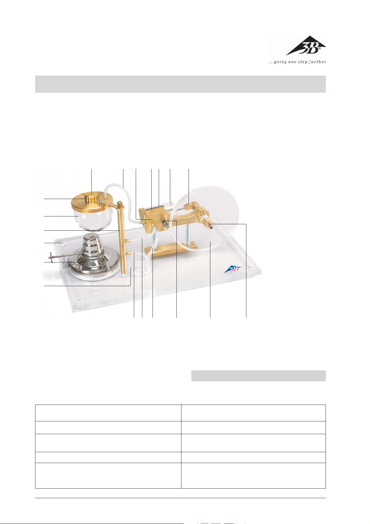
Steam engine, transparent U10055
Instruction Sheet
07/05 ALF
bp
bq
br
bs
bt
bu
PHYSICSPHYSICS
PHYSICS
PHYSICSPHYSICS
1
23
4
1 Condensation hose
2 Exhaust steam hose
789blbmbnbo
3 Drainage hose
4 Spring
5 Flywheel
6 Crankshaft
7 Connecting rod
8 Main cylinder
9 Main piston
bl Cylinder flank
bm Support frame
bn Steam feeding hose
bo Safety valve
bp Boiler cap
bq Boiler
br Exhaust steam pipe
5
6
bs Base plate
bt Spirit burner
bu Condensation beaker
The steam engine is used to demonstrate how an oscillating steam engine functions.
General safety standards applicable to steam engines Specific conformance of steam engine U10055
1. No sharp corners or edges
2. Protection against corrosion 2. No materials that are subject to corrosion have been
3. Temperature limiting for operating elements 3. The wick of the spirit burner can be adjusted.
4. The boiler capacity of the steam engine may not
exceed 2000 cc Maximum operating pressure may not
exceed 1.5 bars.
• The safety standards applicable to the steam engine
are specified in DIN 31000:1979-03.
1. There are no sharp corners or edges on this device.
used.
4. The boiler capacity is 50 cc. The operating pressure is
0.5 bars.
4
1. Safety instructions
Page 2

General safety standards applicable to steam engines
Specific conformance of steam engine U10055
5. An adjustable spring-operated safety valve made of
non-rusting material with a safety threshold of no
more than 3.0 bars (double the operating pressure)
must be provided.
6. The bursting pressure of the boiler should be no less
than 3-times the operating pressure.
7. The water level must be visible, if possible, with the
aid of an inspection window.
8. An easy to understand instruction sheet is required
plus a label with the name or logo of the manufacturer.
• Only put the steam engine into operation if all of the
components are in perfect condition and their functionality is assured. Special attention must be made
to ensure that there are no cracks or any other damage to the glass boiler bq.
• Only use distilled water that has been demineralised
as per VDE 0510. If conventional tap water is used the
associated deposits that form on the safety-relevant
components mean that functionality can no longer
be guaranteed.
• Carefully pour alcohol into the burner bt. Make sure
that nothing spills.
• Never pour in alcohol while the wick is still glowing or
if there is any other open flame in the immediate
proximity.
• Seal the bottle of alcohol immediately after use.
• Keep away from the open flame. Be careful! Only ex-
tinguish the burner flame by means of the attached
cover. Do not blow on the flame in the proximity of
the boiler, as any sudden temperature change could
cause the boiler to crack.
• The boiler may not be heated unless it is filled with
water. For that reason it is important to extinguish
the lamp’s flame before it boils dry.
• Do not touch any components steam carrying, par-
ticularly the boiler bq, hoses 1, 2, 3, bn, steam
exhaust pipe br and support frame bm. Do not
touch the spirit burner bt during or after operating
the steam engine either. Risk of burns!
• Let the steam engine cool before storing.
2. Description, technical data
The oscillating steam engine has been designed for use
in a training and educational environment. In order that
individual operations and dynamic processes should be
observable, particular emphasis has been placed on transparent construction. For that reason the main cylinder
8 and boiler bq are made of heat-resistant special glass
and the flywheel 5 is made of acrylic. The hardened
crankshaft 6 and the connecting rod 7 are ball-bear-
ing mounted. The graphite piston 9 runs dry in the
5. This unit is equipped with an adjustable spring-operated safety valve made of non-rusting material with
a safety threshold of 1.0 bar (double the operating
pressure)
6. The boiler’s bursting pressure is at least 1.5 bars (at
least three times the operating pressure). Each boiler
is checked for safety and leaks by means of a burst
pressure test (2 bars+).
7. The water level is visible at all times because of the glass
boiler.
8. An instruction sheet is supplied with each apparatus.
An appropriate silk-screen printed label is located on
the base plate.
operating cylinder – i.e. without any added lubricant. For
that reason the steam engine runs very quietly and safely for long periods, providing a mechanical power output of approx. 1 W. The safety valve bo is located in the
boiler cap bp. It opens as soon as the boiler pressure
exceeds 1.0 bar. In addition, the machine is also equipped
with a second, independent excess pressure safety mechanism. Up to a pressure of approx. 1.5 bars the steam is
forced into the ducts of the support frame bm and discharged via the condensation hose 1. When the pressure exceeds 1.5 bars the cylinder flank bl is forced away
from the frame because the tension in the spring 4 is
overcome so that the steam can flow unimpeded out of
the steam inlet hole in the frame.
Piston diameter: 19 mm
Piston stroke: 10 mm
Boiler diameter: 50 mm
Boiler volume: 50 ml
Operating time per filling: approx. 20-25 mins
Speed: 800 rpm
Mech. Power output: approx. 1 W
Max. operating pressure: 0.5 bars
Trigger pressure
of the safety valve: 1.0 bars
Minimum boiler
bursting pressure test: 2.0 bars
3. How the apparatus works
Unlike a slide-valve steam-engine, an oscillating steam
engine has a cylinder that rotates on a central shaft causing steam inlet and outlet ducts to open and close. Water
in the boiler begins to boil, and thus steam is generated.
The steam flows via the steam inlet hose bn into the
frame then through the steam inlet hole. As soon the
opening of the cylinder is fed with fresh steam, steam
flows into the cylinder and displaces the piston (Fig. 1, a).
When the piston reaches its lowest point, the steam ducts
are closed. This slack point is passed thanks to the inertia
of a flywheel (Fig 1, b). In the next phase, the piston moves
back, opens the steam outlet and pushes out the steam
5
Page 3

(Fig. 1, c). The steam flows out via the exhaust steam
hose 2 and the exhaust steam pipe br. The condensed
water that accumulates drips out via the condensation
hose 1 into the condensation beaker bu.
ab
When the piston has reached the dead point at the top,
both of the steam ducts are closed again. The flywheel
drags the engine past this top slack point, after which
steam is once again fed in and the procedure repeats
from the start (Fig. 1, d).
Fig. 1: Work cycle of an oscillating steam engine
4. Operation
• Open the boiler cap bp and fill up the boiler with
distilled water (demineralised water conforming to
VDE 0510). Do not fill up the boiler to the brim, maintain an air column of approx. 5 mm. The steam engine functions equally well even if the boiler is only
half-filled. Only the operating duration is correspondingly reduced.
• Light the wick of the spirit burner and heat the boiler.
• Shut the steam inlet opening to enable quicker build
up of pressure.
• After approx. 2 minutes, the water in the boiler be-
gins to boil. From this point onwards, only approx.
2-3 minutes are needed to attain the required operating pressure. Steam flows via the steam feeding
hose into the steam inlet opening. Excess condensed
water drips into the condensate beaker via the drainage hose 3. For this purpose, channels that facilitate collection and transfer of the condensed water
are milled into the frame.
• The engine can now be operated by turning the fly-
wheel in a clockwise direction (while observing the
main cylinder).
dc
• The power of the engine decreases if there is not
enough water left in the boiler. It is not permitted to
heat the boiler if it is not filled with water. The spirit
burner should, therefore, be extinguished at the appropriate time.
• Do not blow out the flame in the proximity of the
boiler. Use the attached cap to extinguish the flame.
• During the cooling process, condensed water is sucked
up from the condensation beaker via the condensation hose, frame and steam feeding hose and transferred into the boiler.
5. Storage and maintenance
• Store the steam engine in a dust-free place.
• To clean use a damp cloth, if necessary, with some
washing-up liquid. Never use solvents or aggressive
cleaning agents to clean the acrylic glass components.
• Frequent use of the apparatus may cause a layer of
soot to deposit on the underside of the boiler bq due
to the constant play of a flame. This, however, can be
dissolved and removed by using a cloth soaked in
acetone.
• In order to prevent water stains appearing, dry thor-
oughly after cleaning.
3B Scientific GmbH • Rudorffweg 8 • 21031 Hamburg • Germany • www.3bscientific.com • Technical amendments are possible
6
 Loading...