

Page 1
3B SCIENTIFIC® PHYSICS
U15033 Standfestigkeitsapparat
Bedienungsanleitung
6/03 ALF
4
3
2
1
®
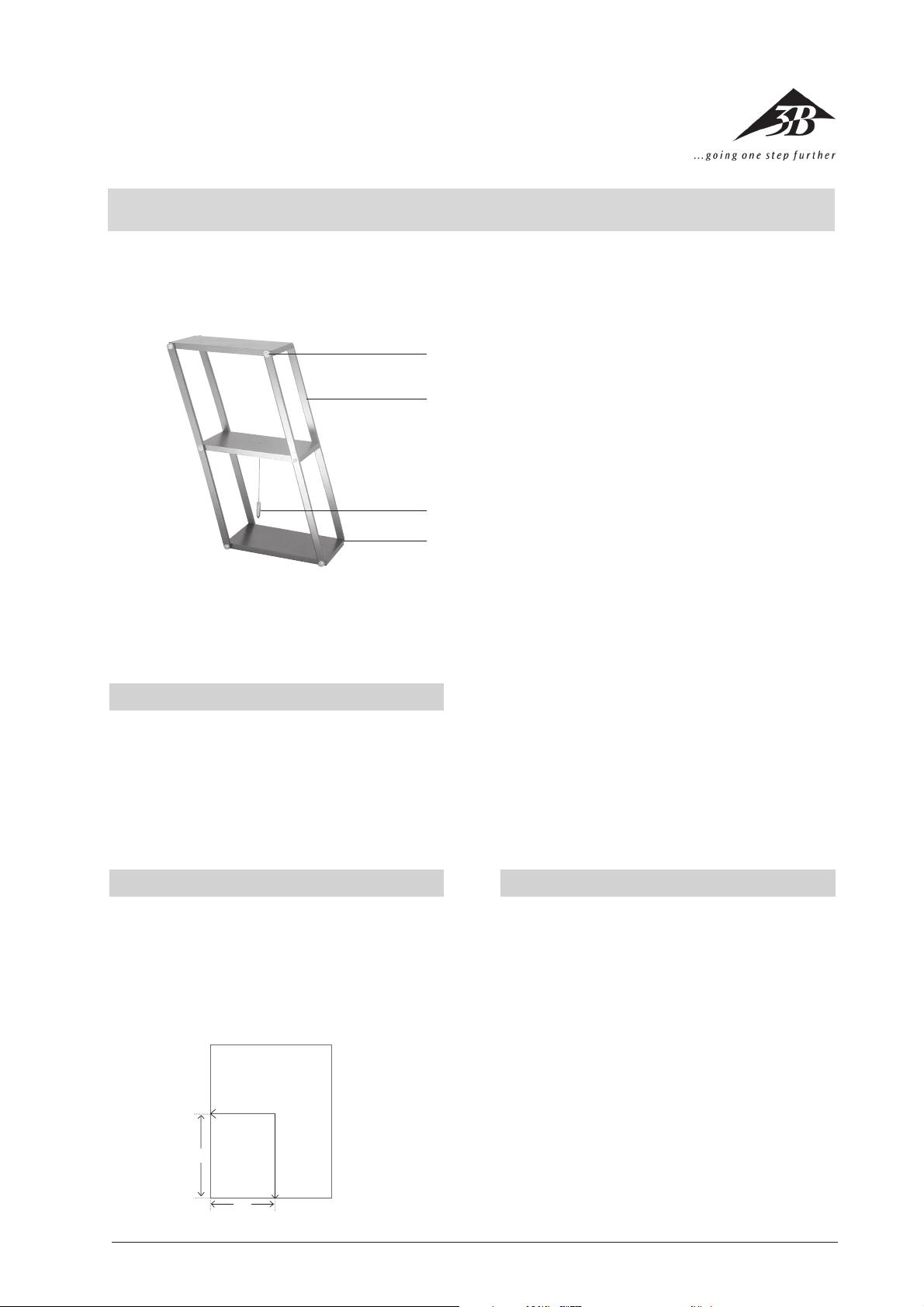
1 Metallplatte
2 Lot
3 Metallstange
4 Gelenk
Der Standfestigkeitsapparat dient zur Demonstration der
Standfestigkeit eines Objekts in Abhängigkeit der
Schwerpunktlage über der Standfläche.
1. Beschreibung, technische Daten
Der Standfestigkeitsapparat besteht aus 3 in gleichen
Abständen übereinanderliegenden Metallplatten, die mit
4 Metallstangen durch Gelenke verbunden sind. Im
Schwerpunkt des Gerätes, in der Mitte der mittleren Platte, ist ein Senklot aufgehängt.
Abmessungen: 180 mm x 150 mm x 290 mm
2. Prinzip
Eine stabile Gleichgewichtslage eines stehenden Körpers
ist nur dann gegeben, wenn das Lot auf den Mittelpunkt
der Standfläche trifft. Die Standfläche hebt dann die Wirkung der am Schwerpunkt angreifenden Schwerkraft auf.
Geht das Lot nicht durch diesen Punkt, greift ein von der
Schwerkraft hervorgerufenes Drehmoment am Schwerpunkt des Körpers an und bringt ihn zum Kippen.
F
S
h
K
G
l
Im Schwerpunkt S greifen zwei Kräfte an, die Gewichtskraft G und horizontal die Kraft F, die versucht den Körper um die Kante K zu kippen. Sie verursacht ein Drehmoment M
moment wirkt das von der Gewichtskraft hervorgerufene Drehmoment M
bleibt der Körper im Gleichgewicht und kippt nicht. Die
Kraft F = Gh/l dient als Maß der Standfestigkeit eines mit
einer Fläche aufliegenden Körpers. Je größer das Gewicht
G und der Abstand l des Auftreffpunktes des Lots von der
Kante K und je kleiner die Höhe h des Schwerpunkts über
der Auflagefläche ist, desto größer ist die Standfestigkeit
des Körpers.
• Den Standfestigkeitsapparat auf eine horizontale Unterlage stellen.
• Dem Gerät verschiedene Neigungen erteilen.
• Gleichgewicht ist stabil, wenn der Schwerpunkt über
der Auflagebasis liegt.
• Gleichgewicht ist labil, wenn der Schwerpunkt über
der Kippungskante liegt. (Ein kleiner Stoß reicht zum
Umkippen aus.)
• Wenn der Schwerpunkt nicht mehr über der Auflagebasis oder über der Kippungskante liegt, kippt der
Standfestigkeitsapparat von selbst um.
• Schwerpunktlage ist durch das Lot immer erkennbar.
• Kraft, die zum Umkippen des Geräts erforderlich ist,
mit einem in der seitlichen Öse befestigtem 10 N
Kraftmesser bestimmen.
= Fh mit K als Drehachse. Diesem Dreh-
kipp
= Gl entgegen. Solange Fh = Gl ist,
gew
3. Bedienung
3B Scientific GmbH • Rudorffweg 8 • 21031 Hamburg • Deutschland • www.3bscientific.com • Technische Änderungen vorbehalten
1
Page 2
3B SCIENTIFIC® PHYSICS
U15033 Stability apparatus with integrated plumb
Instruction sheet
6/03 ALF
®
4
3
2
1
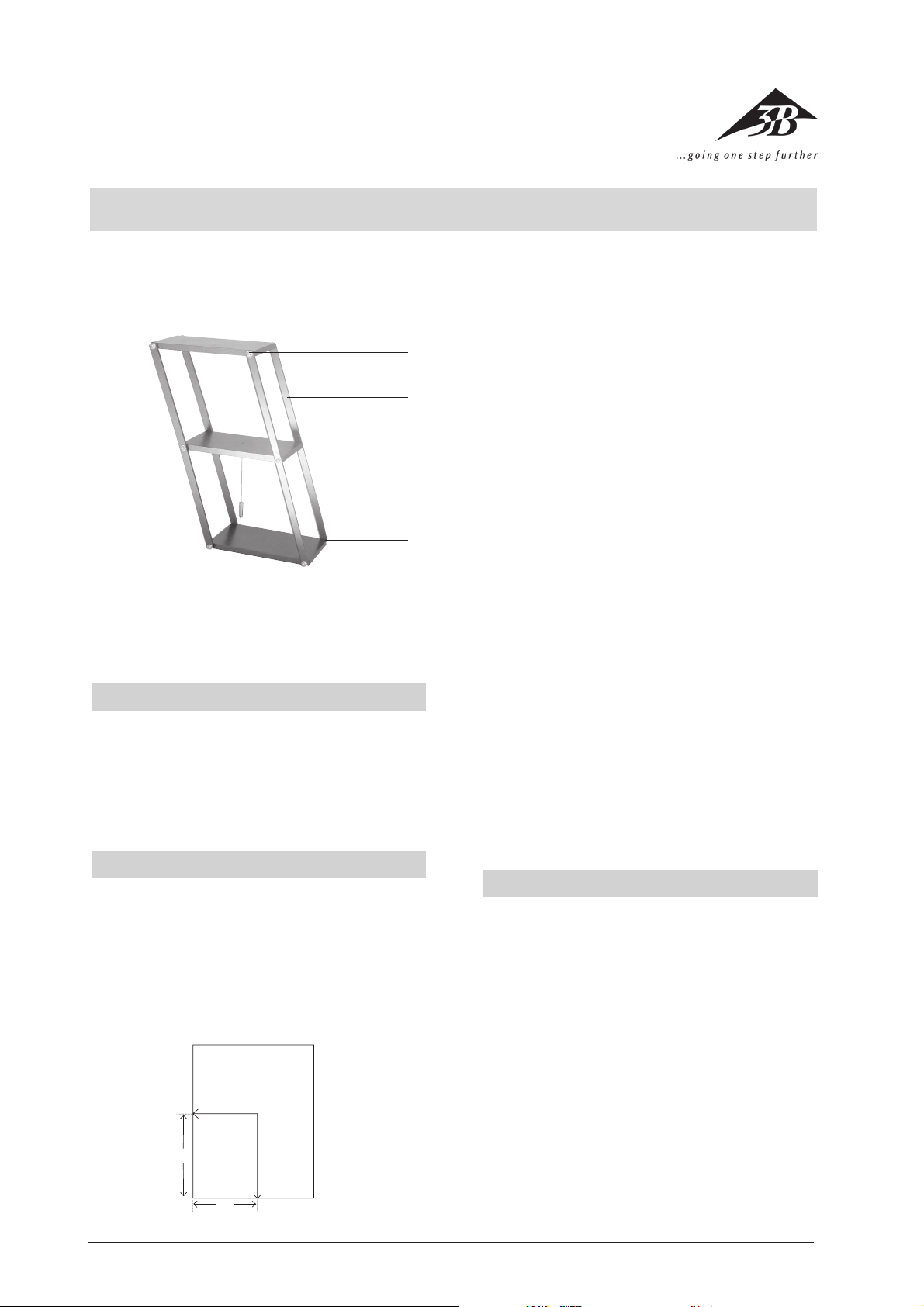
The stability apparatus is used to demonstrate the stability of an object depending on the position of its center
of gravity above the supporting surface.
1. Description, technical data
The stability apparatus consists of 3 steel plates connected by hinges to a frame made up of four steel rods
so that the vertical separation between the plates is equal.
A plumb line hangs suspended from the center of gravity of the apparatus at the mid-point of the middle plate.
Dimensions: 180 mm x 150 mm x 290 mm
1 Steel plate
2 Plumb line
3 Steel rod
4 Hinge
At the center of gravity S there are two forces being exerted, gravity G and the lateral force F, which tends to tilt
the body over the edge K. It causes a moment M
about an axis formed by K. This moment is counteracted
by the moment due to the gravity M
Fh = Gl, the object remains in equilibrium and does not
tip over. The force F = Gh/l serves as a measure for the
stability of an object resting on a surface. The greater the
gravity G, the lower the height h of the center of gravity
above the supporting surface and the greater the distance l from the edge K to the point at which the plumb
line would cross the surface, the more stable the object
will be.
= Gl. As long as
gravity
tilt
= Fh
2. Principle
For a standing object the centre of gravity is only stable if
the plumb line is directly above the centre-point of the
surface at the base of the object. The force of gravity acts
effectively through the centre of gravity of the object
and is equally matched by the reaction of the surface. If
the plumb line is not above the centre of the base, the
force of gravity through the centre of gravity of the object produces a moment which makes the object tend to
tip over.
F
S
h
K
3B Scientific GmbH • Rudorffweg 8 • 21031 Hamburg • Germa ny • www.3bscientific.com • Technical alterations are possible
G
l
• The stability apparatus is placed on a horizontal supporting surface.
• The device is then tilted at various angles.
• Equilibrium is stable if the center of gravity is located
above the support base.
• Equilibrium is unstable if the center of gravity is located directly above the edge that forms the axis of
rotation. (a slight push is enough to tip the apparatus
over.)
• If the center of gravity is no longer located over the
support base or over the tipping edge, the stability
apparatus tips over of its own accord.
• The position of the center of gravity can always be
surmised by the line of the plumb bob.
• To determine the force required to tip the apparatus
over, attach a 10 N dynamometer into the eyelet on
the side of the apparatus.
2
3. Operation
Page 3

3B SCIENTIFIC® PHYSICS
U15033 Appareil de stabilité
Instructions d‘utilisation
6/03 ALF
®
4
3
2
1
Cet appareil permet de démontrer la stabilité d’un objet
en fonction du centre de gravité au-dessus de la surface
d’appui.
1. Description, caractéristiques techniques
L’appareil de stabilité est constitué de 3 plaques métalliques qui sont superposées dans un même écart et reliées par des articulations à 4 tiges métalliques. Un fil à
plomb est accroché au centre de gravité de l’appareil, au
milieu de la plaque médiane.
Dimensions : 180 mm x 150 mm x 290 mm
1 Plaque métallique
2 Fil à plomb
3 Tige métallique
4 Articulation
Deux forces agissent sur le centre de gravité S, la force du
poids G et la force horizontale F qui essaie de faire basculer le corps sur le bord K. Elle provoque un moment
M
= Fh, K représentant le pivot. Le moment M
basc
provoqué par la force du poids réagit contre le moment
M
. Tant que Fh = Gl, le corps reste en équilibre et ne
basc
bascule pas. La force F = Gh/l sert de mesure à la stabilité
d’un corps reposant sur une surface. Plus le poids G est
élevé et l’écart I du point de rencontre du fil à plomb du
bord K important et plus la hauteur h du centre de gravité au-dessus de la surface d’appui est élevée, plus la
stabilité du corps est importante.
pds
= Gl
3. Manipulation
2. Principe
Un corps immobile n’est en équilibre que si le fil à plomb
rencontre le centre de la surface d’appui. La surface d’appui annule alors l’action de la force de pesanteur exercée
sur le centre de gravité. Si le fil à plomb ne traverse pas ce
point, un moment provoqué par la force de pesanteur
agit au centre de gravité du corps et fait basculer ce dernier.
F
S
h
K
3B Scientific GmbH • Rudorffweg 8 • 21031 Hamburg • Allemagne • www.3bscientific.com • Sous réserve de modifications techniques
G
l
• Placer l’appareil de stabilité sur un support horizon-
tal.
• Incliner l’appareil à différents angles.
• L’équilibre est stable lorsque le centre de gravité se
situe au-dessus de la surface d’appui.
• L’équilibre est instable lorsque le centre de gravité se
situe au-dessus du bord de basculement (un petit
choc suffit à faire basculer le corps).
• Lorsque le centre de gravité n’est plus au-dessus de
la surface d’appui ou se situe au-dessus du bord de
basculement, l’appareil de stabilité bascule tout seul.
• Le centre de gravité est toujours indiqué par le fil à
plomb.
• Déterminer la force nécessaire pour faire basculer l’ap-
pareil à l’aide d’un dynamomètre de 10 N fixé dans
l’anneau latéral.
3
Page 4

3B SCIENTIFIC® PHYSICS
U15033 Apparecchio di stabilità
Istruzioni per l’uso
6/03 ALF
®
4
3
2
1
L’apparecchio di stabilità serve per dimostrare la stabilità
di un oggetto in relazione al baricentro sulla superficie di
appoggio.
1. Descrizione, caratteristiche tecniche
L’apparecchio di stabilità è formato da 3 piastre di metallo sovrapposte a distanze uguali, collegate con 4 aste di
metallo mediante giunti. Nel baricentro dell’apparecchio,
nel mezzo della piastra centrale, è appeso un filo a piombo.
Dimensioni: 180 mm x 150 mm x 290 mm
1 Piastra di metallo
2 Piombo
3 Asta di metallo
4 Giunto
Nel baricentro S agiscono due forze, la forza peso G e
orizzontalmente la forza F, che cerca di ribaltare il corpo
dello spigolo K. Tale forza genera un momento M
con K come asse di rotazione. A questo momento si contrappone il momento M
di gravità. Finché Fh = Gl, il corpo rimane in equilibrio e
non cade. La forza F = Gh/l esprime la misura della stabilità di un corpo cha poggia su una superficie. Quanto
maggiori sono il peso G e la distanza l del punto d’incidenza del filo a piombo dallo spigolo K e quanto minore
è l’altezza h del baricentro rispetto alla superficie d’appoggio, tanto maggiore sarà la stabilità del corpo.
= Gl determinato dalla forza
Fpeso
Mcad
= Fh
3. Comandi
2. Principio
Un corpo verticale è in una posizione di equilibrio statico
solo se il filo a piombo coincide con il centro della sua
superficie di appoggio. La superficie d’appoggio annulla
l’azione della forza di gravità che agisce sul baricentro. Se
il filo a piombo non passa per questo punto, sul baricentro
del corpo agisce un momento determinato dalla forza di
gravità che causa la caduta del corpo.
F
S
h
K
3B Scientific GmbH • Rudorffweg 8 • 21031 Hamburg • Germania • www.3bscientific.com • Con riserva di modifiche tecniche
G
l
• Riporre l’apparecchio di stabilità su una base orizzontale.
• Dare all’apparecchio diverse inclinazioni.
• L’equilibrio è statile, se il baricentro rientra nella
base d’appoggio.
• L’equilibrio è precario, se il baricentro è al di sopra
dello spigolo di ribalmento. (Basta un piccolo colpo
per determinare la caduta.)
• Quando il baricentro non si trova più all’interno
della superficie d’appoggio o sopra lo spigolo di
ribaltamento, l’apparecchio di stabilità cade da solo.
• Il filo a piombo consente sempre di identificare la
posizione del baricentro.
• Determinare la forza necessaria per ribaltare l’apparecchio con un dinamometro da 10 N fissato al foro
laterale.
4
Page 5

3B SCIENTIFIC® PHYSICS
U15033 Aparato de estabilidad
Instrucciones de uso
6/03 ALF
4
®
1 Placa de metal
3
2
1
Este aparato se utiliza para la demostración de la estabilidad de un objeto en función de la posición del centro
de gravedad sobre la superficie de apoyo.
1. Descripción, datos técnicos
El aparato de estabilidad se compone de tres placas metálicas colocadas una sobre otra, a la misma distancia, y
unidas en articulación mediante cuatro varillas metálicas.
Del centro de gravedad del aparato, esto es, el punto medio de la placa central, cuelga una plomada.
Dimensiones: 180 mm x 150 mm x 290 mm
2. Principio
Un cuerpo estático sólo se encuentra en una posición de
equilibrio estable cuando la plomada coincide con el punto medio de la superficie. La superficie compensa entonces el efecto que ejerce la fuerza de la gravedad sobre el
centro de gravedad. Si la plomada no señala a ese punto,
un par de giro, provocado por la fuerza de gravedad,
actúa sobre el centro de gravedad del cuerpo, y éste se
vuelca.
F
S
h
K
G
l
2 Plomada
3 Varilla metálica
4 Articulación
Sobre el centro de gravedad S actúan dos fuerzas, la fuerza del peso G y, horizontalmente, la fuerza F, que tiende
a inclinar el cuerpo hacia el borde K. Esta fuerza provoca
un par de giro M
Contra este par de giro actúa el par de giro M
generado por la fuerza de gravedad. Mientras se cumpla
que Fh = Gl, el cuerpo se mantiene en equilibrio y no se
inclina. La fuerza F = Gh/l sirve como medida de la estabilidad de un cuerpo apoyado en una superficie. Cuanto
mayor sea el peso G y la distancia l del punto marcado
por la plomada, con respecto al extremo K, y cuanto
menor sea la altura h del centro de gravedad sobre la
superficie de apoyo, mayor será la estabilidad del cuerpo.
• Coloque el aparato de estabilidad sobre una base
horizontal.
• Incline el aparato de diferentes maneras.
• El equilibrio es estable cuando el centro de gravedad
está sobre la base de apoyo.
• El equilibrio es frágil cuando el centro de gravedad se
encuentra sobre el borde de inclinación. (Basta un
ligero golpe para provocar el volcamiento.)
• Si el centro de gravedad no está sobre la base de
apoyo, o sobre el extremo de inclinación, el aparato
de estabilidad se volcará por sí solo.
• Siempre se puede determinar el centro de gravedad
mediante la plomada.
• Determine la fuerza necesaria para hacer volcar el
aparato con un dinamómetro 10 N fijado en el orificio lateral.
= Fh con K como eje de torsión.
vuelco
3. Servicio
peso
= Gl,
3B Scientific GmbH • Rudorffweg 8 • 21031 Hamburg • Alemania • www.3bscientific.com • Se reservan las modificaciones técnicas
5
Page 6

3B SCIENTIFIC® PHYSICS
U15033 Aparelho para a estabilidade
Instruções para o uso
6/03 ALF
®
4
3
2
1
O aparelho para a estabilidade serve para a demonstração da estabilidade de um objeto dependendo da localização do centro de gravidade sobre a superfície de apoio.
1. Descrição, dados técnicos
O aparelho para a estabilidade é formado por 3 placas de
metal dispostas uma sobre a outra a distâncias iguais,
elas estão associadas por articulações a 4 barras de metal. No centro de gravidade do aparelho, no centro da
placa intermediária, encontra-se um prumo.
Medidas: 180 mm x 150 mm x 290 mm
1 Placa de metal
2 Prumo
3 Barra de metal
4 Articulação
Duas forças agem sobre o centro de gravidade S, a força
de gravidade G e na horizontal a força F, a qual procura
derrubar o corpo pela aresta K. Portanto, ela cria um
momento de rotação M
ção. Esse momento de rotação age contra o momento
de rotação criado pela força de gravidade M
quanto Fh = Gl é dado, o corpo mantém o equilíbrio e
não cai. A força F = Gh/l serve de medida da estabilidade
de um corpo apoiado numa superfície. Quanto maior
for o peso G e a distância l do ponto de encontro do
prumo à aresta K e quanto menor for a altura h do centro
de gravidade sobre a superfície de apoio, maior será a
estabilidade do corpo.
= Fh, sendo K o eixo de rota-
derr
= Gl. En-
grav
2. Princípio
Só se dá uma situação de equilíbrio para um corpo em
pé quando o prumo atinge o centro da superfície de
apoio. A superfície de apoio compensa então o efeito da
ação da força de gravidade sobre o centro de gravidade.
Caso o prumo não se posicionar nesse ponto, então o
momento de rotação criado pela força de gravidade age
sobre o centro de gravidade do objeto levando-o a vacilar e a cair.
F
S
h
K
3B Scientific GmbH • Rudorffweg 8 • 21031 Hamburg • Alemanha • www.3bscientific.com • Sob reserva de modificações técnicas
G
l
• Colocar o aparelho para a estabilidade sobre uma
superfície horizontal.
• Inclinar o aparelho em diferentes direções.
• O equilíbrio será estável no caso em que o centro de
gravidade se encontre sobre a base de apoio.
• O equilíbrio será instável quando o centro de gravidade se encontre na aresta de queda (um leve golpe
será o suficiente para derrubar).
• Se o centro de gravidade não se encontrar mais nem
sobre a base de apoio nem sobre a aresta de queda,
então o aparelho para a estabilidade cai por si só.
• O centro de gravidade pode sempre ser reconhecido
graças ao prumo.
• Determinar a força necessária para derrubar o aparelho com um dos dinamômetros de 10 N fixados nos
anéis laterais.
6
3. Utilização
 Loading...