

Page 1
3B SCIENTIFIC
Langensiepen Current Balance U8496820
Instruction Sheet
06/09 ERL
®
PHYSICS
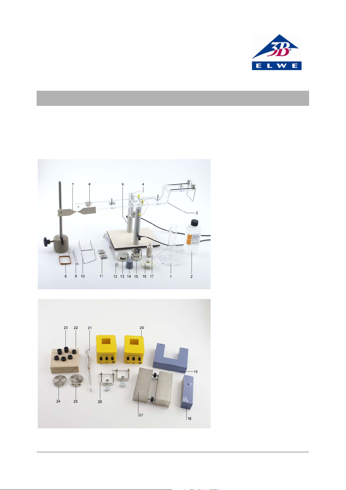
1 Cylinder for friction brake
2 Glycerine
3 Balance beam with pointer
4 Current input terminals
5 Stand
6 Counterweight
7 Pointer for zero calibration
8 Coil, 5 turns
9 Aluminium tube
10 Conductor loop
11 10 g weight
12 Dynamometer
(from accessory set)
13 Drive weight, 100 g
14 Rubber bung
15 Drive weight ,200 g
16 Nylon thread
17 Piston for friction brake
18 Yoke
19 Transformer core
20 Coil, 600 turns
21 Dynamometer 0,1 N
22 Storage block
23 Spacer rings
24 200 g weight
25 100 g weight
26 Fixing clamp
27 Pole shoe set
1
Page 2
1. Safety instructions
All the components of the instrument are safe to work
with, provided that they are used in accordance with
instructions and regulations.
The transformer core, yoke and pole shoes should be
handled carefully to avoid the risk of injuries resulting
from their considerable weight.
In experiments involving a strong magnetic field, do
not allow any ferromagnetic materials to come near
the instrument, as they would be powerfully attracted
towards it with a risk of damage or injury, for example
through trapping of fingers.
Equipment that is to be connected to the mains must
be checked for any damage before it is used.
2. Description
The Langensiepen current balance is used for experiments on electrodynamics and Lorentz forces and
involves measurements in which the force on a conductor in a magnetic field is balanced mechanically.
3. Equipment supplied
1 Stand with agate cup bearings for balance beam
1 Balance beam with pointer and terminals for cur-
rent connections
1 Set of conductor loops
1 Coil, 5 turns
1 Pointer for zero calibration
1 Hydrodynamic friction brake
2 Special connecting leads
1 Bottle of glycerine (250 ml)
2 Drive weights, 100 g and 200 g
1 Counterweight weight
2 19 g weights
1 Reel of nylon thread
1 Instruction sheet
1 Transformer core with yoke and fixing clamp
1 Pole shoes set
2 100 g weights
1 200 g weight
2 Coils, 600 turns
1 Storage block
1 Dynamometer, 0.1 N
10 Spacer rings
4. Operation
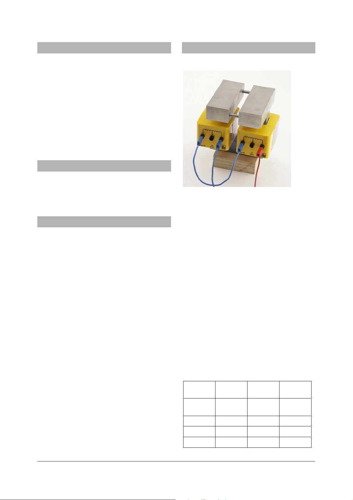
4.1 Generating a strong magnetic field
Fig. 1
The strong magnetic field generator is assembled as
shown in Figure 1 using the following components
from the accessories set U8496818: U-core (19), two
coils (20), pole shoes (27).
The connecting leads chosen must be long enough to
ensure that they do not cause any mechanical obstruction to the operation of the current balance.
The pole shoes (27) are placed on the core (19) without
any special fixing. They rest in place securely enough
under their own weight, and when the field is applied
they are held more firmly. The distance between the
pole shoes is determined by the choice of spacer rings
(23), giving a separation of 10, 15 or 20 mm when
used singly, or 25, 30, 35 or 40 mm by combining
them. The field between the pole shoes is approximately uniform.
It is recommended that a stabilised DC power supply
U33020 is used as the voltage source for excitation of
the magnet (see Fig. 3). When switching the field on or
off, the large inductance of the system must be taken
into account by avoiding switching a large current.
The following table contains some guideline data on
the magnetic flux density B that can be generated
with different values of the coil current and spacing of
the pole shoes. The magnet set-up consists of the Ucore with two 600-turn coils connected in series.
Pole shoe
separation
Excitation
current
2 A 0.18 T 0.15 T 0.12 T
1 A 0.13 T 0.09 T 0.07 T
0.5 A 0.06 T 0.04 T 0.03 T
1 cm 2 cm 3 cm
Flux B Flux B Flux B
2
Page 3

4.2 Current balance
F
F
⋅
F
⋅
Fig. 2
The current balance (Fig. 2) consists of a stand (5), the
balance beam (3), a pointer for zero calibration (7),
three interchangeable conductor loops (10) and a coil
with 5 turns (8).
The current in the loop or coil is applied via the stand
(maximum continuous current 2 A, or up to 4 A for
short periods).
The conductor loops are of different lengths. An aluminium tube (9) can be clipped into the 10 cm loop to
increase the conductor cross-section.
After fitting one of the loops in place, the instrument
must first be mechanically balanced. The zero position
is marked by setting a pointer. Coarse adjustment is
carried out using 10g weights (11), which are placed
on the pegs provided on the beam. That is followed by
a fine adjustment using the counterweight on the
beam.
4.3 Induction set-up
Fig. 3
The induction set-up (Fig. 3) consists of a current balance and a strong magnetic field, to which a drive for
moving the current loop (10) into or out of the nearuniform magnetic field between the pole shoes is
added. The drive provided by the weights (13, 15, 24,
25) in combination with the friction brake produces a
steady upward or downward movement of the cobductor loop (10) or the coil (8).
A choice of different spacer rings (23) between the
pole shoes gives a range of magnetic flux densities
with the same excitation current.
The induced voltage during the movement of the loop
or coil, as measured by a microvoltmeter (U8530501),
can remain constant over a period of up to 30 seconds.
4.4 Force on a current-carrying conductor
Fig. 4
Initially the distance between the pole shoes should
be set at 10 mm. The current loop (length l = 5 cm) is
connected in position and the current balance is adjusted for equilibrium.
The strong magnetic field is switched on and a DC
current (I = 2 A) is passed through the current loop
(using a second meter to measure the current).
The balance is restored to the equilibrium condition
by raising the dynamometer.
If the magnetic field generator is then shifted slightly
(without disturbing the current loop), the adjustment
of the current balance remains unaltered, showing
that the magnetic field between the pole shoes is
uniform.
When the length l of the loop and the current I pass-
ing through it are changed, the following can be observed:
l~
and I~F, also lI~
Varying the magnetic field excitation current or the
separation between the pole shoes also changes the
measured force.
Therefore the coefficient of proportionality in the
relationship where
lI~
can also be changed as a
3
Page 4

result changing the field arrangement. This is one
F
appropriate way of characterising the field set-up.
Definition:
lIB
⋅⋅= or
F
B⋅= .
lI
The measured force is independent of the crosssectional area of the conductor loop. This can be easily shown by clipping the aluminium tube that is provided into the loop (l = 10 cm).
Elwe Didactic GmbH • Steinfelsstr. 6 • 08248 Klingenthal • Germany • www.elwedidactic.com
3B Scientific GmbH • Rudorffweg 8 • 21031 Hamburg • Germany • www.3bscientific.com
Subject to technical amendments
© Copyright 2009 3B Scientific GmbH
 Loading...