

Page 1
1
3B SCIENTIFIC
Apparatur zum kritischen Punkt U104001
Bedienungsanleitung
09/10 MH/JS
23
22
19
18
17
®
PHYSICS
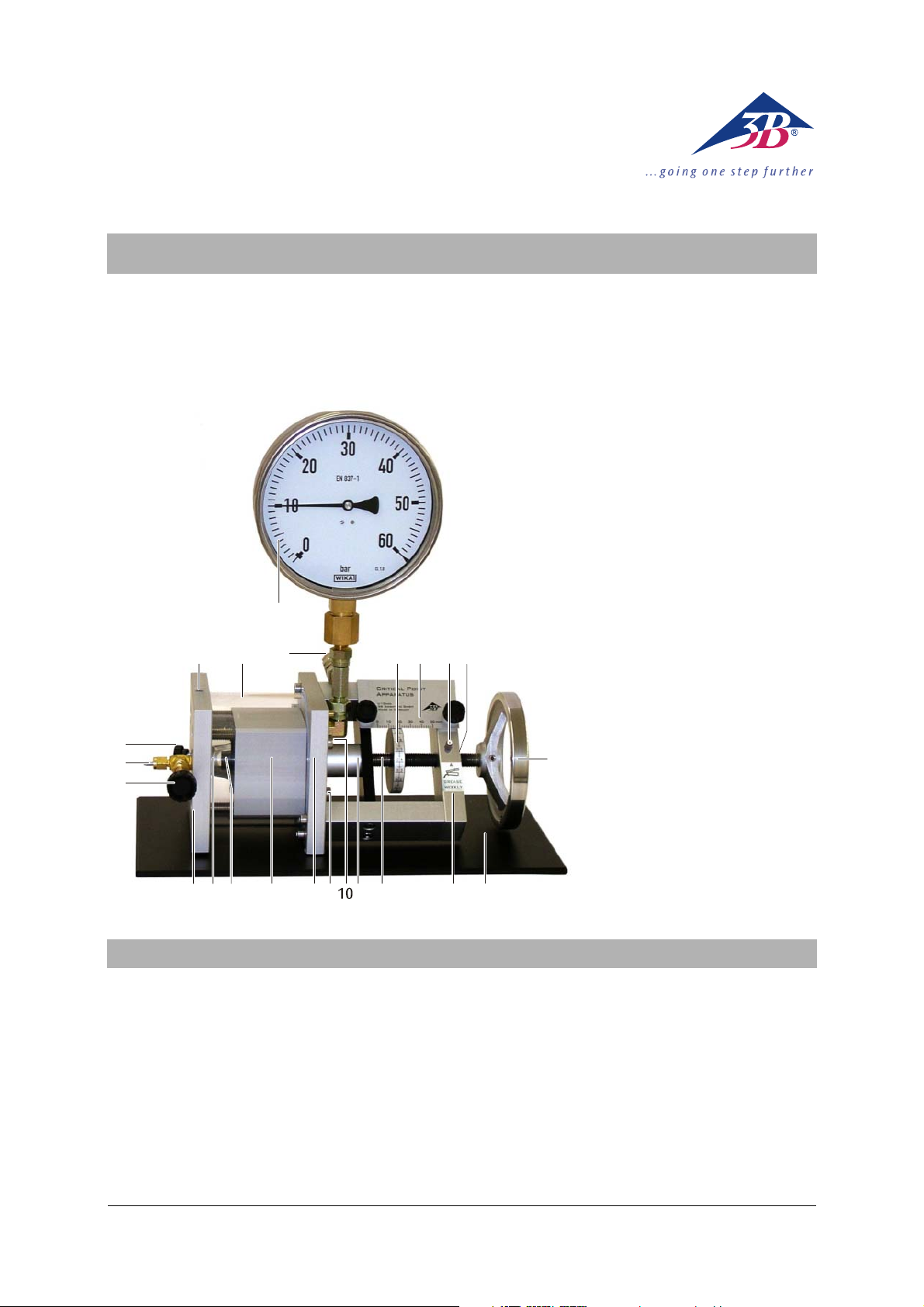
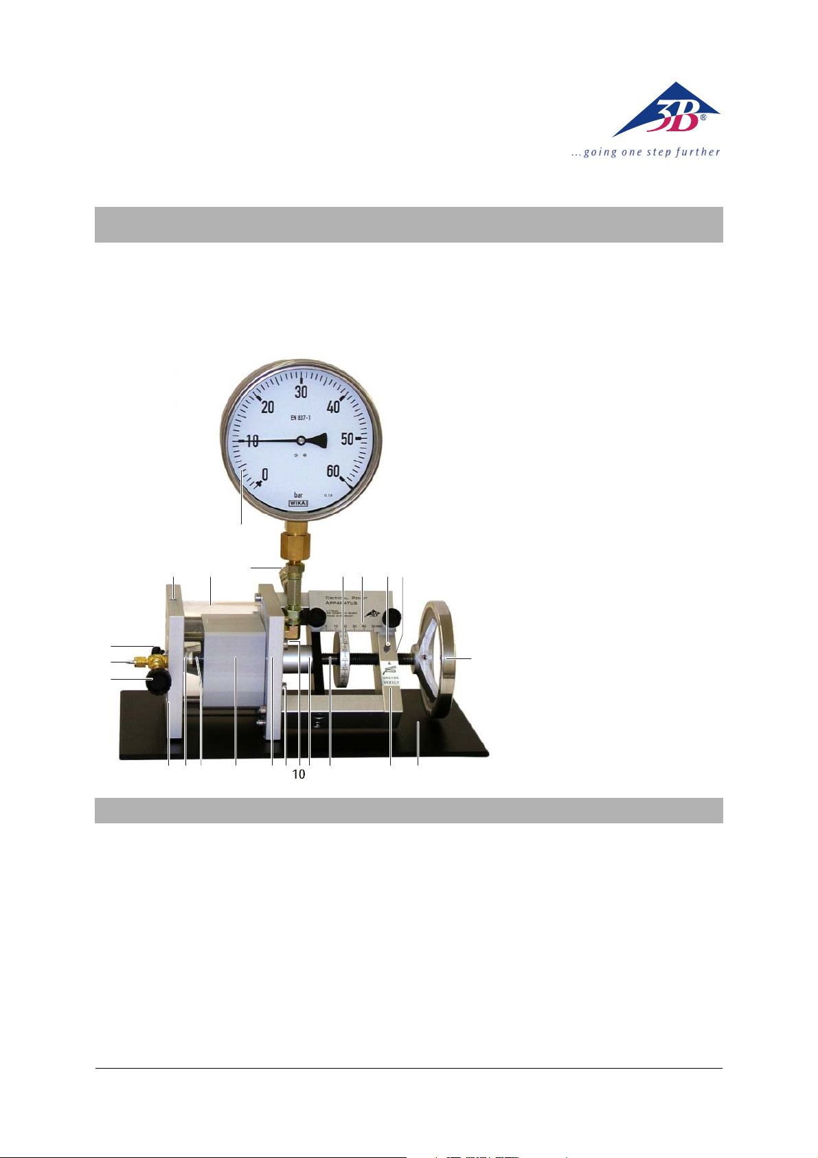
1 Mitdrehende Skala
2 Feststehende Skala
3 Schmiernippel
4 Gewindebuchse
5 Handrad
6 Grundplatte
7 Bügel
8 Gewindestange mit Kolben
9 Kolbenschutz
10 Abfluss für Temperiermedium
11 Zufluss für Temperiermedium
12 Basisplatte
13 Zylinder
14 Hutdichtung
15 Messzelle
1220 21
3 4
5
16 Ventilplatte
17 Regulierventil
18 Gasanschlussstutzen 1/8"
(für Minican®-Gaskanister)
19 Spülventil
20 Bohrung für Temperaturfühler
21 Temperiermantel
22 Sicherheitsventil
23 Manometer (Überdruckanzeige)
1516 14
Die Apparatur zum kritischen Punkt ist bei Auslieferung mit Hydrauliköl jedoch nicht mit Testgas gefüllt.
Vor der Befüllung mit Testgas sollte eine Volumenkalibrierung gemäß Abschnitt 6 mit Luft als idealem Gas
durchgeführt werden.
Die Befüllung mit Testgas selbst ist in Abschnitt 7
beschrieben.
Experimentelle Untersuchungen sind in Abschnitt 8
erläutert.
Hinweise zur Einlagerung bei längeren Pausen gibt
Abschnitt 9.
1213
876
91
1. Inhalt der Bedienungsanleitung
Wegen der unvermeidlichen Diffusion des Testgases
durch die Hutdichtung ist nach längeren Standzeiten
und vor einer geplanten testgasfreien Einlagerung der
Apparatur das Hydrauliköl entsprechend Abschnitt 10
zu entgasen.
Die Gewindebuchse im Bügel muss regelmäßig gefettet und in größeren Abständen überprüft werden.
Dies ist in Abschnitt 11 beschrieben.
Die in Abschnitt 12 beschriebenen Wartungsarbeiten
sind erst dann erforderlich, wenn die Gummiteile
durch Alterung in ihrer Funktion beeinträchtigt sind.
1
Page 2

2. Sicherheitshinweise
3. Beschreibung
Bei bestimmungsgemäßem Gebrauch ist der Umgang
mit der Apparatur zum kritischen Punkt ungefährlich,
da Experimentator und Apparatur durch ein Sicherheitsventil geschützt werden. Dennoch sind einige
Vorsichtsregeln unbedingt zu beachten:
• Gesamte Bedienungsanleitung sorgfältig lesen
und beachten.
• Maximal zulässige Werte für Druck und Tempera-
tur (60 bar und 10–60°C) nicht überschreiten.
• Apparatur nur unter Aufsicht betreiben.
• Schutzbrille tragen.
Eine Temperaturerhöhung darf nur bei geringem
Druck und möglichst bei reiner Gasphase in der Messzelle vorgenommen werden.
• Vor einer Temperaturerhöhung das Handrad
möglichst bis zum maximalen Volumen herausdrehen.
Während des Einstellens darf das Sicherheitsventil
nicht in die Richtung von Personen oder Gegenständen zeigen, die durch ein Herausschießen der Ventilkappe verletzt bzw. zerstört werden könnten. Auch
beim normalen Experimentieren ist auf die Ausrichtung des Sicherheitsventils zu achten:
• Apparatur grundsätzlich so aufstellen, dass das
Sicherheitsventil nicht in die Richtung von Personen oder zu schützenden Gegenständen zeigt.
• Zur Einstellung des Sicherheitsventils mit den
Armen von vorne um die Apparatur herum nach
hinten zum Sicherheitsventil greifen.
Die Hutdichtung wird bei Überlastung zerstört:
• Niemals bei offenem Regulierventil oder Spülven-
til, d.h. ohne Gasgegendruck in der Messzelle, einen Druck über 5 bar einstellen.
• Niemals bei geschlossenen Ventilen durch Zu-
rückdrehen des Handrades einen Unterdruck erzeugen.
Im Bügel befindet sich eine Gewindebuchse, die als
sicherheitsrelevantes Bauteil einzustufen ist (siehe
Abschnitt 9).
• Gewindebuchse alle 100 Zyklen schmieren.
• Gewindebuchse einmal jährlich prüfen.
Um Korrosionschäden im Gerät zu vermeiden,
• Gemisch aus Wasser und Kühlerschutzmittel im
Verhältnis 2:1 als Temperiermedium verwenden.
Die Apparatur zum kritischen Punkt ermöglicht die
Untersuchung von Kompressibilität und Verflüssigung
eines Gases, die Bestimmung des kritischen Punktes
und die Aufnahme der Isothermen des p-VDiagramms (Clapeyron-Diagramm). Als Testgas wird
Schwefelhexafluorid (SF
) eingesetzt, das mit einer
6
kritischen Temperatur von 318,6 K (45,5°C) und einem
kritischen Druck von 3,76 MPa (37,6 bar) einen einfachen Aufbau ermöglicht.
Die Apparatur enthält eine durchsichtige Messzelle in
besonders dichter und druckfester Ausführung. Das
Volumen in der Messzelle wird durch fein dosierbare
Drehung eines Handrades verändert, wobei die Volumenänderung mittels einer feststehenden und einer
mitdrehenden Skala mit einer Genauigkeit von einem
1/1000 des Maximalvolumens abgelesen werden
kann. Der Druckaufbau erfolgt durch ein Hydrauliksystem mit Rizinusöl in einer für medizinische Anwendungen zugelassenen Qualität. Messzelle und
Hydrauliksystem sind durch eine Hutdichtung getrennt, die sich bei einer Volumenvergrößerung einrollt. Durch diese Konstruktion ist die Druckdifferenz
zwischen Messzelle und Ölraum praktisch vernachlässigbar. Ein Manometer misst anstelle des Gasdruckes
den Öldruck, ohne ein Totvolumen in der Messzelle
zu beanspruchen. Bei der Beobachtung der Übergänge von der gasförmigen in die flüssige Phase und
umgekehrt kann daher sowohl die Entstehung des
ersten Flüssigkeitstropfens wie auch das Verschwinden der letzten Gasblase beobachtet werden.
Die Messzelle ist von einer transparenten Wasserkammer umhüllt. Über einen Umwälzthermostaten lässt
sich somit eine konstante Temperatur mit hoher Genauigkeit einstellen, wobei die Temperatur über ein
Thermometer abgelesen und kontrolliert werden kann.
Die guten Ablesemöglichkeiten von Volumen, Druck
und Temperatur erlauben die Aufnahme von p-V-
oder pV-p-Diagrammen ohne großen Aufwand mit
qualitativ richtigen Ergebnissen. Mit einer druck- und
temperaturabhängigen Volumenkorrektur lassen sich
auch quantitativ richtige Ergebnisse erzielen, die
einem Vergleich mit Literaturwerten standhalten.
4. Lieferumfang
1 Apparatur zum kritischen Punkt, gefüllt mit Hyd-
rauliköl (Rizinusöl) jedoch ohne Testgas (SF
), mit
6
montiertem Gasanschlussstutzen für MINICAN®-
Gaskanister und Schutz für Gasanschluss
1 Öl-Befüll-Vorrichtung
1 Sechskant-Winkelschraubendreher 1,3 mm
(für Madenschraube der mitdrehenden Skala)
1 Kunststoffschlauch, 3 mm Innendurchmesser
1 Rohrverschraubung für 1/8" (SW 11)
1 Fettpresse
2
Page 3
5. Technische Daten
A
J
Δ⋅=
Δ
6. Volumenkalibrierung
Schwefelhexafluorid:
6.1 Vorbemerkung:
Kritische Temperatur: 318,6 K (45,5°C)
Kritischer Druck: 3,76 MPa (37,6 bar)
Kritisches Volumen: 197,4 cm
Kritische Dichte: 0,74 g/Mol
3
/Mol
Q
Maximalwerte:
Temperaturbereich: 10–60°C
Maximaldruck: 6,0 MPa (60 bar)
Schwellwert des
Sicherheitsventilsventils: 6,3 MPa (63 bar)
Theoretische
Dauerfestigkeit: 7,0 MPa (70 bar)
Theoretischer
R
S
Berstdruck: >20,0 MPa (200 bar)
Materialien:
Probengas: Schwefelhexafluorid
Hydrauliköl: Rizinusöl
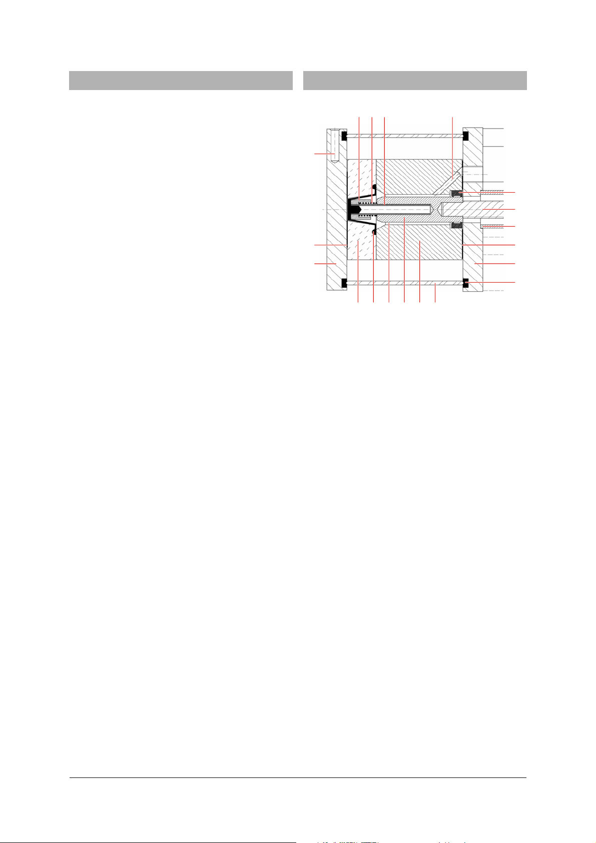
Fig. 1: Schnitt durch die Apparatur mit
Messzelle: Acrylglas
Temperiermantel: Acrylglas
Empf. Temperiermedium: Gemisch aus Wasser und
Kühlerschutzmittel im Verhältnis 2:1
Volumenbestimmung:
Kolbendurchmesser: 20,0 mm
Kolbenfläche: 3,14 cm
Verstelltes Volumen: 3,14 cm
Maximalvolumen: 15,7 cm
2
2
× Verstellweg
3
Skalenteilung
für Verstellweg: 0,05 mm
Maximaler Verstellweg: 50 mm
Druckbestimmung:
Manometer: Klasse 1.0
(max. 1% Abweichung vom
Skalenendwert)
Messgröße: Überdruck
Anzeige: bis 60 bar
Manometerdurchmesser: 160 mm
Eine Drehung am Handrad dreht den Kolben über die
Gewindestange in den Zylinder hinein oder heraus,
wodurch sich das Volumen im Ölraum ändert (siehe
Fig. 1). Da Öl nahezu inkompressibel ist und bis auf
die Hutdichtung alle anderen Teile nahezu starr sind,
bewirkt die Volumenänderung im Ölraum eine Deformation der Hutdichtung und damit eine nahezu
gleich große Volumenänderung ΔV
Für ΔV
Anschlüsse:
Bohrung
mit
für Temperaturfühler: 6 mm ∅
Anschlüsse
für Temperiermittel: 7 mm ∅
Anschluss
des Reduzierventils: 1/8 Zoll ∅
Gasanschluss: 1/8’’ (3,17 mm) ∅
(bei Auslieferung)
Allgemeine Daten:
Abmessungen: 380 x 200 x 400 mm
Masse: ca. 7 kg
3
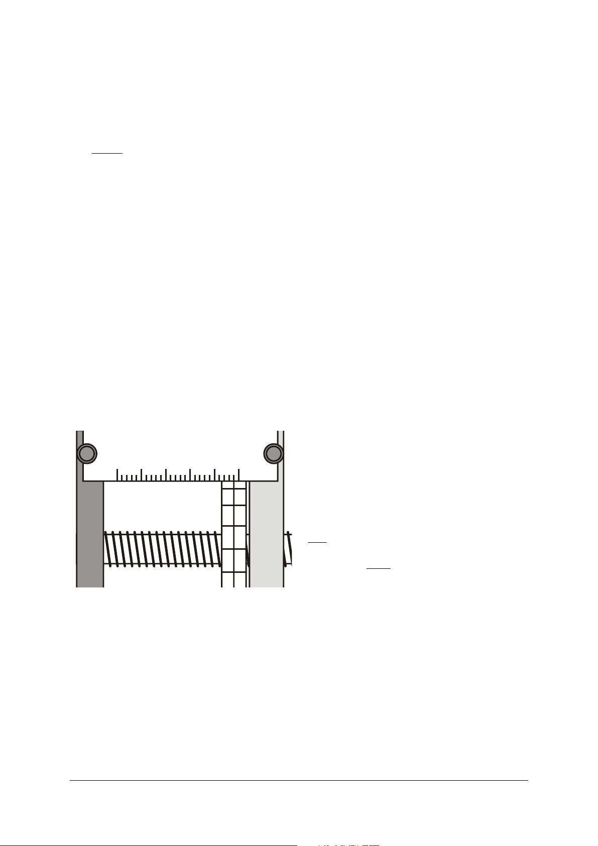
Der Kolbenweg wird in Schritten von 2 mm auf der
feststehenden Skala angezeigt, Zwischenwerte können
auf der mitdrehenden Skala in Schritten von 0,05 mm
abgelesen werden.
Die feststehende Skala kann nach Lösen der beiden
Rändelschrauben verschoben, die mitdrehende Skala
nach Lösen der (zwischen den Skalenpositionen 0 9
und 1 0 angeordneten) Madenschraube verschoben
sowie um die Gewindestange gedreht werden.
NOP M
B C E F
Messzelle (A), Hutdichtung (B),
Ölraum (C), Kolben (D),
Zylinder (E), Temperiermantel (F),
Silikondichtung (G),
Basisplatte (H),
quadratische Gummidichtung (I),
Kolbenschutz (J),
Gewindestange (K),
Dichtring (L),
Manometeranschluss (M),
Führungsrohr (N),
Feder (O), Hülse (P),
Bohrung für Temperaturfühler (Q),
runde Gummidichtung (R) und
Ventilplatte (S)
gilt also in erster Näherung:
G
sAV
G
(1)
2
cm143,A = und Δs = Verstellweg des Kolbens.
D
in der Messzelle.
G
L
K
I
H
G
3
Page 4
6.2 Nullpunktkalibrierung:
T
⋅
Der Nullpunkt der Volumenskala muss durch eine
Kalibrierung ermittelt werden.
Hierzu bedient man sich der Tatsache, dass sich Luft
im Druckbereich von 1–50 bar und im Temperaturbereich von 270–340 K wie ein ideales Gas verhält (der
Realgasfaktor weicht um weniger als 1% von 1 ab).
Daher gilt bei konstanter Temperatur (z.B. bei Raumtemperatur) für zwei Kolbenwege s
zugehörigen Drücke p
und p1 der eingeschlossenen
0
und s1 sowie die
0
Luft
spsp ⋅=⋅ (2)
1100
Mit
s Δ⋅
=
1
sss Δ+=
ergibt sich nach Umstellung:
10
p
0
s
pp
−
(3)
01
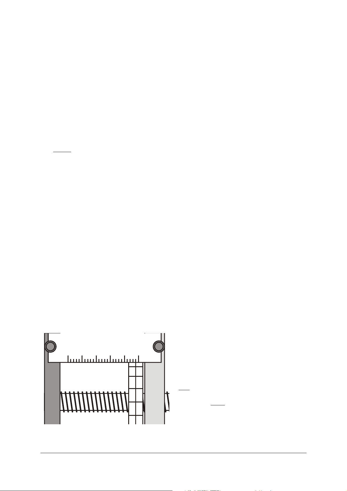
Grobjustierung der Skalen:
• Regulierventil weit öffnen.
• Madenschraube der mitdrehenden Skala um eine
halbe Umdrehung lösen (die Skala lässt sich jetzt
auf der Gewindestange leicht verdrehen, ohne
das Handrad zu bewegen; dem selbstständigen
Verdrehen wirkt aber noch ein federndes Druckstück entgegen).
• Handrad bis zum merklichen Widerstand heraus-
drehen.
• Ohne das Handrad zu bewegen, mitdrehende
Skala auf der Gewindestange verdrehen, bis die
0,0-Markierung oben ist und auf der feststehenden Skala ca. 48 mm angezeigt werden.
• Rändelschrauben der feststehenden Skala lösen
und die Skala seitlich verschieben, bis der Strich
bei 48 mm exakt über der Mittellinie der mitdrehenden Skala liegt (siehe Fig. 2).
• Rändelschrauben wieder anziehen; dabei darauf
achten, dass die feste Skala nicht auf die mitdrehende Skala drückt.
100 20304050mm
00
19
18
17
16
Fig. 2: Anzeige der Kolbenposition 48,0 mm
Nullpunktkorrektur:
• Regulierventil schließen (der Druck in der Mess-
zelle entspricht jetzt dem Umgebungsdruck
1 bar; das Manometer zeigt im Rahmen der Messgenauigkeit den Überdruck 0 bar an).
• Handrad hineindrehen, bis 15 bar Überdruck
angezeigt werden (Absolutdruck
• Kolbenposition s
stellweg
• Nullpunktkorrigierte Kolbenposition s
Δs = s
ablesen und daraus den Ver-
1
– s1 berechnen.
0
p
= 16 bar).
1
1,korr
Gl. 3 berechnen.
• Mitdrehende Skala auf den korrigierten Wert
einstellen und ggf. die feststehende Skala nochmals verschieben.
• Handrad ggf. etwas herausdrehen und die mit-
drehende Skala mit der Madenschraube fixieren.
Messbeispiel:
p
= 1 bar, p1 = 16 bar, p1 – p0 = 15 bar
0
s
= 48,0 mm, s1 = 3,5 mm, Δs = 44,5 mm
0
das ergibt
s
= 2,97 mm.
1,corr
Die mitdrehende Skala ist daher so zu verstellen, dass
anstelle von 3,50 mm nun 2,97 mm angezeigt wird.
Hinweis:
Nach dieser Nullpunktkalibrierung erhält man bereits
qualitativ richtige Messwerte. Bezüglich
T und p wer-
den die Isothermen im zweiphasigen Bereich bis zum
kritischen Punkt auch quantitativ richtig erfasst. Allerdings sind besonders im flüssigen Bereich die gemessenen Isothermen etwas zu weit gespreizt.
6.3 Ausführliche Kalibrierung:
Der genaue Zusammenhang zwischen dem Volumen
V
in der Messzelle und der Skalenanzeige s ist von der
G
eingefüllten Ölmenge im Ölraum abhängig. Außerdem dehnt sich der Ölraum proportional zum Druck
geringfügig aus, was auf die Rohrfeder im Manometer
zurückzuführen ist. Zusätzlich dehnt sich Rizinusöl
bei einer Temperaturerhöhung stärker aus, als der
Rest der Apparatur, wodurch der Druck mit zunehmender Temperatur leicht übermäßig ansteigt. All
diese Effekte können nach einer entsprechenden
Kalibrierung mit Luft als idealem Gas herausgerechnet werden.
Die ideale Gasgleichung lautet:
Vp
Rn
(4)
⋅=
mit
J
3148,R =
molK
p
=
0
nach
4
Page 5

Dabei lässt sich der Absolutdruck gemäß
β−⋅β
(
)
p = p
+ 1 bar (6)
e
aus dem abgelesenen Überdruck
p
berechnen. Für
e
die absolute Temperatur gilt:
T = ϑ + ϑ
mit ϑ0 = 273,15°C (7)
0
Das Volumen berechnet sich gemäß
sAV ⋅=
G
mit
(8)
2
cm143,A = und dem „wirksamen“ Kolbenweg s.
Der wirksame Kolbenweg ergibt sich aus dem abgelesenen Kolbenweg
s
wie folgt:
e
++=
psss
pe 0
ϑ⋅
(9)
ϑ
Einsetzen in Gl. 4 ergibt:
⋅ϑ⋅β−⋅β++⋅
Apssp
pe
0
ϑ
ϑ+ϑ
0
0
=⋅−
Rn
(10)
• Zur Aufnahme einiger Messwerte das Volumen in
der Messzelle oder die Temperatur am Thermostaten variieren, Einstellung des stationären
Gleichgewichts abwarten und Druck ablesen.
• Mit einer geeigneten Anpassungssoftware die
s
Parameter
Fehlerquadratsumme
• Falls gewünscht die mitdrehende Skala um den
Wert
, βP, βϑ und n so bestimmen, dass die
0
Q minimal wird (vgl. Gl. 11).
s
verdrehen, wodurch diese Korrektur her-
0
ausfällt.
Mit den so bestimmten Parametern wird gemäß Gl. 9
s
aus der abgelesenen Kolbenposition
Kolbenposition
s berechnet und daraus gemäß Gl. 8
die „wirksame“
e
das kalibrierte Messzellenvolumen.
Messbeispiel:
Tab. 1: Messwerte zur Kalibrierung
Nimmt man mehrere Messpunkte bei verschiedenen
Temperaturen und Drücken auf, so ist der Term
n
()
⎛
⎜
=
Q
∑
⎜
=
1i
⎝
p
ϑ+ϑ
0
⋅ϑ⋅β−⋅β++⋅
Apssp
ϑ
ii0ii
zu berechnen und die freien Parametern
2
⎞
⎟
⋅−
Rn
(11)
⎟
⎠
s
, βP, βϑ und
0
n so zu wählen, dass Q minimal wird.
Zusätzlich erforderlich (vgl. Abschnitt 8):
1 Kompressor oder
Fahrradluftpumpe und Fahrradventil
1 Bad-/Umwälzthermostat U14400
1 Digital-Sekunden-Taschenthermometer U11853
1 Tauchfühler
NiCr-Ni Typ K, -65°C bis 550°C U11854
2 Silikonschläuche, 1 m U10146
1 l Kühlerschutzmittel mit Korrosionsschutz-Additiven
für Aluminium-Motoren (z.B. Glysantin® G30 der
Fa. BASF)
Durchführung der Kalibrierung:
• Umwälzthermostat wie in Abschnitt 8 beschrie-
benen anschließen und mit Wasser-KühlerschutzGemisch füllen.
• Kunststoffschlauch mit Innendurchmesser 3 mm
auf den Gasanschlussstutzen 1/8" stecken.
• Regulierventil öffnen.
• Kolben mit dem Handrad z.B. bis zur Position
46,0 mm herausdrehen.
• Mit Kompressor oder einer Fahrrad-Luftpumpe
einen Luft-Überdruck von ca. 3–8 bar in der Messzelle erzeugen.
• Regulierventil schließen.
i
s
/ mm
e
ϑ
p / bar
1 40,0 20,0°C 6,6
2 20,0 20,0°C 12,4
3 10,0 20,0°C 23,3
4 5,0 20,0°C 41,8
5 3,5 20,0°C 53,9
6 5,0 20,0°C 41,8
7 5,0 10,0°C 38,9
8 5,0 30,0°C 45,3
9 5,0 40,0°C 49,0
10 5,0 50,0°C 53,5
Es ergeben sich folgende Parameterwerte:
s
= 0,19 mm,
0
mm
bar
,
ϑ
0230
,=β
P
mm
0340,=β
grd
n = 0,00288 mol.
und
5
Page 6
7. Befüllung mit Testgas
m
7.1 Umgang mit Schwefelhexafluorid:
Schwefelhexafluorid (SF6) ist ungiftig und für den
Menschen vollkommen ungefährlich. Der MAK-Wert,
bei dem Erstickungsgefahr durch Sauerstoffverdrängung droht, beträgt 1000 ppm. Das entspricht ca. 6
Messzellen-Füllungen pro 1 m
Allerdings ist SF
sehr umweltschädlich und weist
6
3
Luft.
einen 24.000-mal stärkeren Treibhauseffekt auf als
. Daher sollten nicht größere Mengen in die Um-
CO
2
welt freigesetzt werden.
7.2 Gasanschluss über eine feste Rohrleitung:
Zusätzlich erforderlich:
1 SF
-Gasflasche mit einer vom Gashersteller bzw.
6
–vertreiber empfohlenen Gasarmatur, z.B. Gasflasche
SH ILB und Regulierventil Y11 L215DLB180 von Fa.
Airgas (www.airgas.com)
1 Rohrleitung mit Außendurchmesser 1/8" und ggf.
Reduzierstücke, z.B. von Fa. Swagelok (www.swagelok.com)
1 Maulschlüssel SW 13, 1 Maulschlüssel SW 11
Gemäß den Grundsätzen einer „guten Laborpraxis“ ist
insbesondere bei regelmäßiger Nutzung der Apparatur zum kritischen Punkt der Gasanschluss über eine
feste Rohrleitung zu empfehlen.
Eine Befüllung beginnt mit mehreren Spülvorgängen
zum Herausspülen der Luft aus der Rohrleitung. Die
Zahl der Spülvorgänge hängt ab von der Rohrleitungslänge (genauer vom Verhältnis Leitungsvolumen/
Messzellenvolumen). Vom Treibhausgas SF
sollte da-
6
bei möglichst wenig in die Umwelt freigesetzt werden.
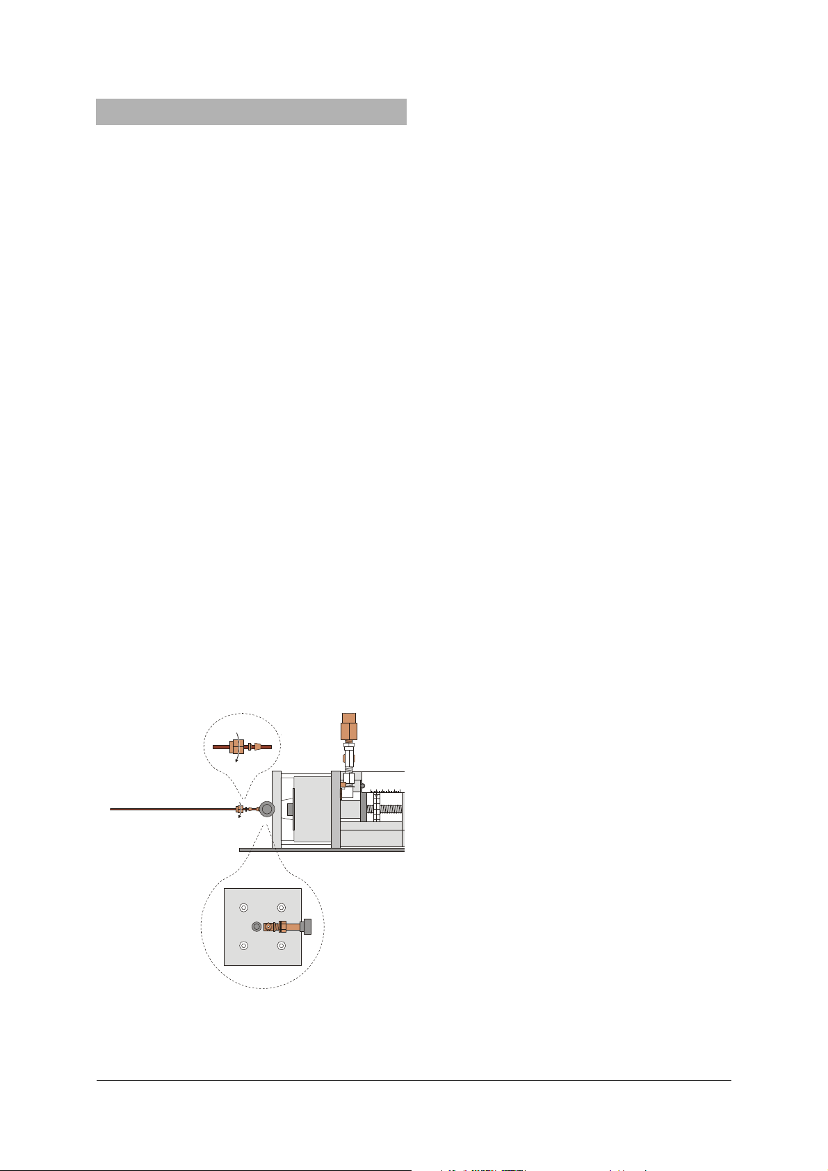
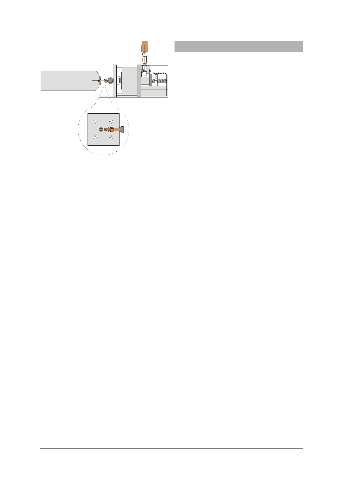
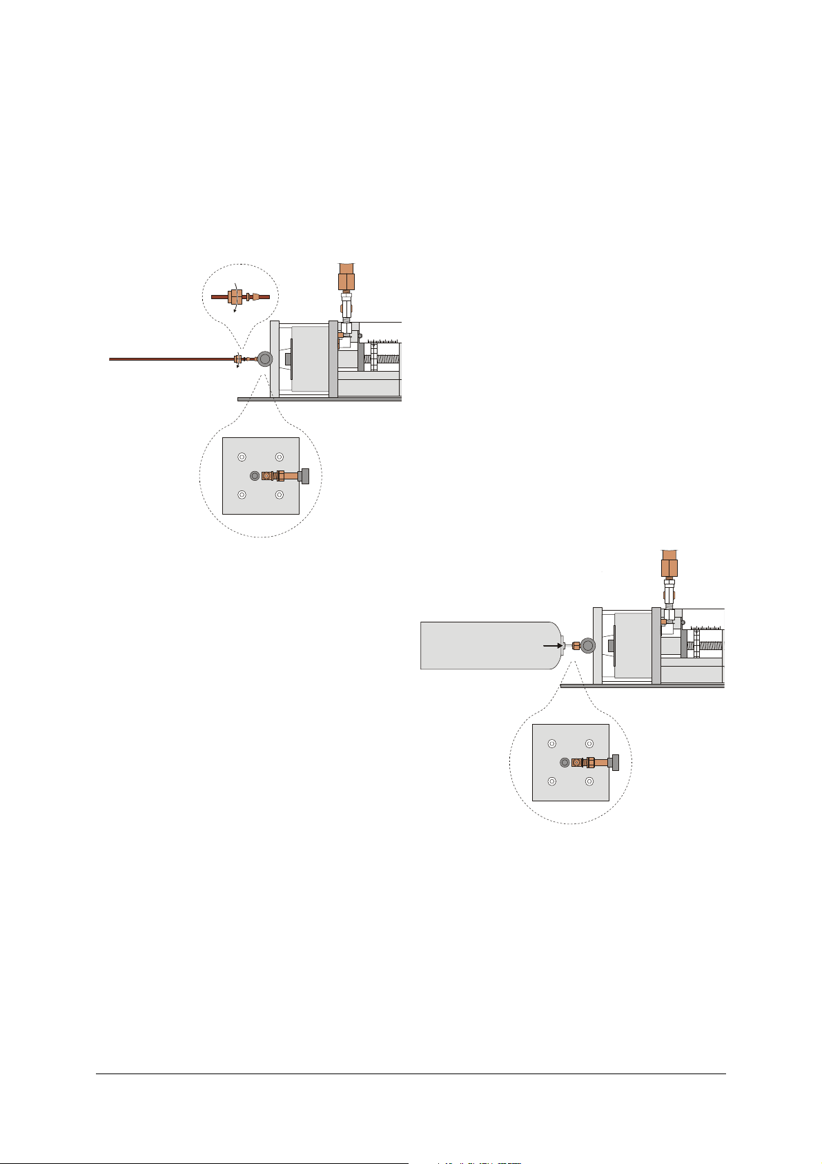
Anschluss der festen Rohrleitung:
100 20304050m
00
19
18
17
16
15
ab
Fig. 3: Anschluss der festen Rohrleitung
(a) Spülventil, (b) Regulierventil
• Ggf. Schutz für Gasanschluss abziehen und Gasan-
schlussstutzen 1/8" durch Lösen der Überwurfmutter (SW 11) entfernen.
• Rohrleitung (ggf. mit Reduzierstücken) an die
Gasarmatur anschließen.
• Mitgelieferte Rohrverschraubung beginnend mit
der Überwurfmutter auf die Rohrleitung schieben
(siehe Fig. 3, Reihenfolge und Ausrichtung wie mit
dem Kabelbinder vorgegeben!).
• Rohrleitung in das Regulierventil stecken und die
Überwurfmutter soweit festziehen, bis sich die
Rohrleitung gerade nicht mehr mit den Fingern
verschieben lässt.
• Regulierventil mit einem Maulschlüssel (SW 13)
kontern und Überwurfmutter um weitere 270°
festdrehen.
Nun ist die Verbindung gasdicht. Beim späteren Lösen
der Überwurfmutter ist das Regulierventil ebenfalls
mit einem Maulschlüssel zu kontern.
Herausspülen der Luft:
• Kolben mit Handrad auf Position 10 mm stellen.
• Regulierventil langsam öffnen und SF
einströmen
6
lassen, bis ca. 10 bar angezeigt werden.
• Regulierventil schließen.
• Spülventil wenig öffnen, bis die Druckanzeige auf
fast 0 bar abgesunken ist.
• Spülventil schließen.
Befüllung mit Testgas:
• Nach mindestens vier Spülvorgängen das Regu-
lierventil öffnen, bis wiederum 10 bar angezeigt
werden.
• Regulierventil schließen.
• Kolben mit Handrad auf z.B. 46 mm zurückdre-
hen.
• Regulierventil langsam öffnen und bei Erreichen
von 10 bar wieder schließen.
7.3 Gasbefüllung aus einer MINICAN®:
Zusätzlich erforderlich:
1 MINICAN®-Gaskanister mit SF
, z.B. von Fa. Westfa-
6
len (www.westfalen-ag.de)
Bei gelegentlicher Nutzung der Apparatur, ist es güns-
tiger, das Testgas aus einem MINICAN®-Gaskanister zu
entnehmen. Der Gasanschluss einer MINICAN® ist
ähnlich aufgebaut wie ein Ventil an einer handelsüblichen Sprühdose, d.h. es öffnet, wenn die MINICAN®
direkt auf den Gasanschlussstutzen gedrückt wird.
Auch hier beginnt eine Befüllung mit mehreren Spülvorgängen zum Herausspülen der Luft.
6
Page 7
100 20304050m
m
00
19
18
SF
6
ab
17
16
15
Fig. 4: Einfüllen des Testgases aus einem MINICAN®-Gas-
kanister (a) Spülventil, (b Regulierventil
Herausspülen der Luft:
• Ggf. Schutz für Gasanschluss abziehen
• Kolben mit Handrad auf Position 10 mm stellen.
• MINICAN® mit SF
nach Entfernen der Schutzkap-
6
pe an den Gasanschlussstutzen ansetzen.
• MINICAN® anpressen, Regulierventil (b) langsam
öffnen und SF
einströmen lassen, bis ca. 10 bar
6
angezeigt werden.
• Regulierventil schließen.
• Spülventil wenig öffnen, bis die Druckanzeige auf
fast 0 bar abgesunken ist.
• Spülventil schließen.
Befüllung mit Testgas:
• Nach mindestens vier Spülvorgängen MINICAN®
anpressen, Regulierventil langsam öffnen und SF
6
einströmen lassen, bis ca. 10 bar angezeigt werden.
• Regulierventil schließen.
• Kolben mit Handrad auf z.B. 46 mm zurückdre-
hen.
• MINICAN® anpressen, Regulierventil langsam
öffnen und bei Erreichen von 10 bar wieder
schließen.
7.4 Empfehlung für kurze Unterbrechungen:
Die Gasfüllung kann einige Tage in der Messzelle
verbleiben.
Wenn keine Experimente durchgeführt werden, sollte
der Kolben mit dem Handrad in eine möglichst
druckarme Position - also z.B. auf 46 mm - zurückgedreht werden.
Nach Möglichkeit sollte die Apparatur immer mit dem
Temperiermedium gefüllt bleiben.
8. Experimente
8.1 Experimenteller Aufbau:
Zusätzlich erforderlich:
1 Bad-/Umwälzthermostat U14400
1 Digital-Sekunden-TaschenThermometer U11853
1 Tauchfühler
NiCr-Ni Typ K, -65°C bis 550°C U11854
2 Silikonschläuche, 1 m U10146
1 l Kühlerschutzmittel mit Korrosionsschutz-Additi-
ven für Aluminium-Motoren (z.B. Glysantin® G30
der Fa. BASF)
• Apparatur in zur Beobachtung der Messzelle gut
geeigneter Höhe aufstellen und so ausrichten,
dass das Sicherheitsventil nicht auf Personen oder
zu schützende Gegenstände gerichtet ist.
• Silikonschläuche vom Ausfluss des Umwälzther-
mostaten zum Zufluss des Temperiermantels und
vom Ausfluss des Temperiermantels zum Zufluss
des Umwälzthermostaten anschließen.
• Temperiermedium aus 2 Volumenteilen Wasser
und 1 Volumenteil Kühlerschutzmittel herstellen.
• Umwälzthermostat füllen.
8.2 Qualitative Beobachtungen:
Flüssiger und gasförmiger Zustand, dynamischer Zustand beim Phasenübergang, Ausbildung der Übergangspunkte bei verschiedenen Temperaturen.
• Volumen durch Drehen am Handrad und Tempe-
ratur am Thermostaten unter Beachtung der Sicherheitshinweise variieren.
• Zur leichteren Beobachtung der Grenzfläche zwi-
schen Flüssigkeit und Gas vorsichtig am Aufbau
wackeln.
In der Nähe des kritischen Punktes kann auch die
kritische Opaleszenz beobachtet werden: Durch einen
ständigen Wechsel zwischen flüssigem und gasförmigen Zustand in kleinen Bereichen der Messzelle entsteht eine Art „Nebel“ und das Schwefelhexafluorid
erscheint trübe.
8.3 Messung von Isothermen im p-V-Diagramm:
• Bei maximalem Volumen die gewünschte Tempe-
ratur am Umwältzthermostaten einstellen.
• Schrittweise das Volumen in der Messzelle bis zur
Kolbenposition 10 mm verkleinern, Einstellung
des stationären Gleichgewichts abwarten und
Druck ablesen.
• Anschließend bei möglichst kleinem Volumen
beginnend das Volumen schrittweise bis zur gleichen Kolbenposition 10 mm vergrößern, Einstellung des stationären Gleichgewichts abwarten
und Druck ablesen.
• Überdrücke in Absolutdrücke und die Kolbenpositi-
7
Page 8

onen gemäß Abschnitt 6 in Volumina umrechnen.
Im Bereich kleiner Volumina wird das stationäre
Gleichgewicht schneller beim Übergang von hohen
Drücken zu niedrigen Drücken – also vom kleineren
zum größeren Volumen – erreicht, da die Phasengrenzfläche des Phasenübergang von flüssig nach
gasförmig auch durch Dampfblasen überall in der
Flüssigkeit gebildet wird. Die Gleichgewichtseinstellung dauert dann etwa 1–5 min, wobei die Messpunkte am Rand des zweiphasigen Gebietes die längste
Zeit benötigen.
Der empfohlene Grenzwert von 10 mm bezieht sich
auf einen Einfülldruck von 10 bar. Im erlaubten Temperaturbereich liegt oberhalb dieses Wertes sicher
noch keine Flüssigphase vor. Der Grenzwert wandert
bei höheren Einfülldrücken nach „rechts“.
8.4 Messung von Isochoren im p-T-Diagramm:
• Gewünschte Ausgangstemperatur und anschlie-
ßend gewünschtes Volumen einstellen.
• Temperatur schrittweise absinken lassen.
• Einstellung des stationären Gleichgewichts abwar-
ten und Druck ablesen.
Im zweiphasigen Bereich bilden die so gemessenen
Messpunkte die Dampfdruckkurve.
Die Gleichgewichtseinstellung dauert nach jeder
Temperaturänderung bis zu 20 min, da zunächst das
Wasserbad und die Messzelle die gewünschte Temperatur erreichen müssen.
8.5 Bestimmung der Gasmasse:
Ausblasen des Gases aus der Messzelle in eine gasdichte
Plastiktüte und anschließende Wägung:
• Ggf. Rohrleitung entfernen und Gasanschlussstut-
zen montieren.
• Handrad weit herausdrehen, z.B. auf 46 mm.
• Regulierventil wenig öffnen und das Gas über den
Gasabschlussstutzen in die Plastiktüte entlassen.
• Regulierventil schließen.
• Masse des ausgeblasenen Gases bestimmen, dabei
Leergewicht der Tüte und Luftauftrieb beachten.
• Volumen der Messzelle verkleinern, bis der Druck
in der Messzelle wieder den ursprünglichen Wert
erreicht hat.
• Aus der Volumendifferenz vor und nach der Ent-
leerung und dem noch vorhandenen Volumen in
der Messzelle die ursprünglich vorhandene Gasmasse berechnen.
Abgleich mit Literaturwerten:
Mit Hilfe von Tabellenwerken, z.B. Clegg et al. [4],
wird alternativ aus Messwerten ϑ, p und V die Gas-
masse in der Messzelle berechnet.
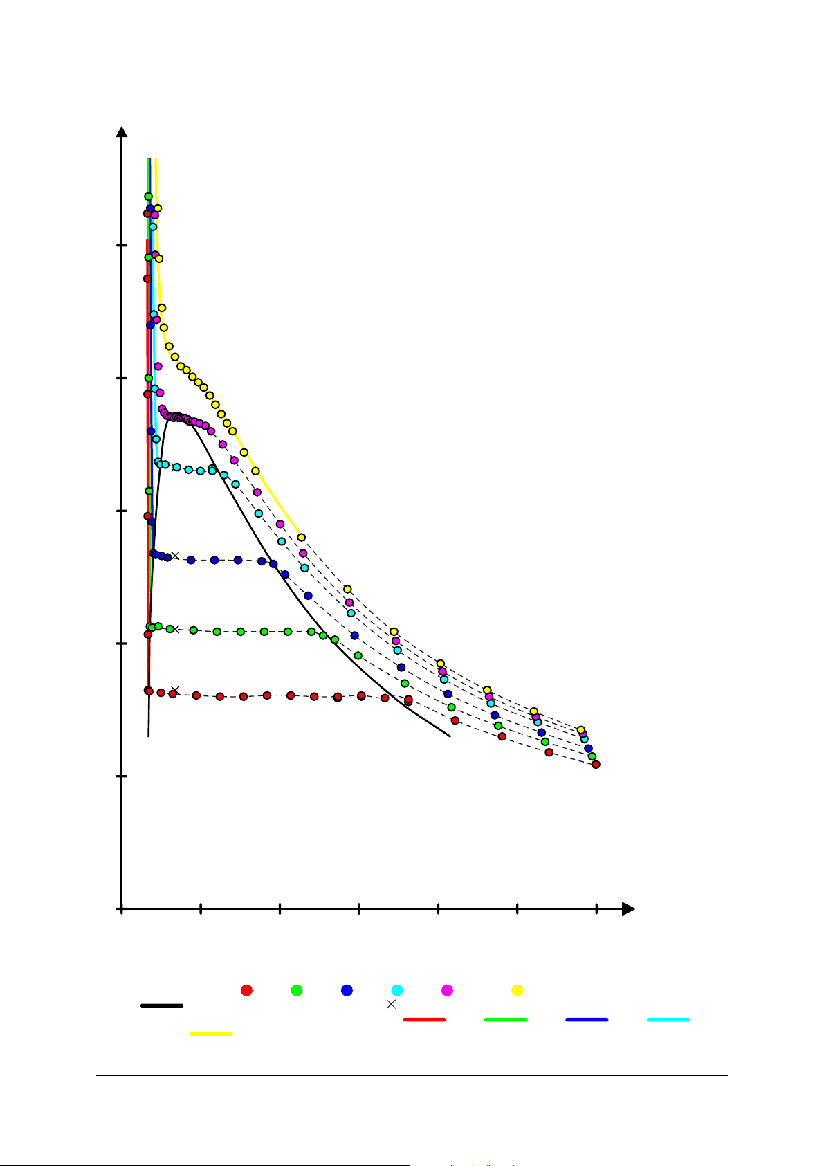
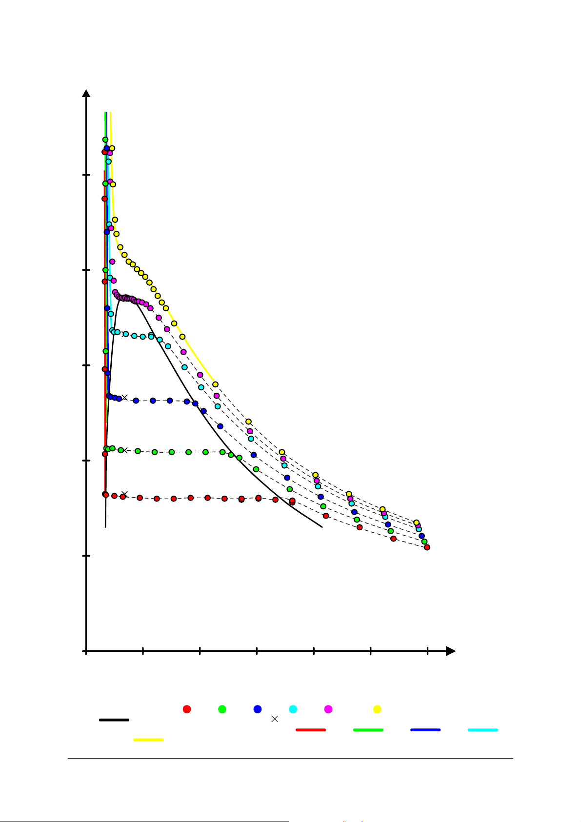
8.6 Auswertung:
In Fig. 5 ist zu erkennen, dass mit der relativ einfachen Apparatur Messwerte erzielt werden können, die
einen Vergleich mit den auch im Diagramm eingezeichneten Literaturwerten nicht zu scheuen brauchen.
8.7 Literatur:
[1,2] Sulphur Hexafluoride, Firmenschrift S.27[1],30[2]
und Solvay Fluor und Derivate GmbH, Hannover,
Germany, 2000
[3] Otto und Thomas, in: Landolt-Börnstein - Zahlenwerte und Funktionen, II Band, 1. Teil, SpringerVerlag, Berlin, 1971
[4] Clegg et al., in: Landolt-Börnstein - Zahlenwerte
und Funktionen, II Band, 1. Teil, Springer-Verlag,
Berlin, 1971
[5] Din, F.: Thermodynamic Functions of Gases, Vol. 2,
Butterworths Scientific Publications, London, 1956
[6] Vargaftik, N. B.: Handbook of Physical Properties
of Liquids and Gases, 2nd ed., Hemisphere Publishing
Corporation, Washington, 1983
[7] Nelder, J. und Mead, R.: Comp. J., Vol. 7, S. 308,
1965
9. Einlagerung für längere Unterbrechungen
Wenn über einen längeren Zeitraum keine Experimente geplant sind, wird das Testgas abgelassen und
der Kolben in die „Ruheposition“ gedreht, in der der
konische Teil der Hutdichtung minimal eingebeult ist
und nicht gegen die Messzelle drückt.
• Ggf. Apparatur abkühlen lassen und Kolben mit
dem Handrad in eine möglichst druckarme Position drehen.
• Testgas über das Spülventil ablassen.
• Kolben mit dem Handrad in die „Ruheposition“
bei etwa 5 mm drehen.
• Spülventil wieder schließen.
• Vor der endgültigen Einlagerung unbedingt das
Hydrauliköl gemäß Abschnitt 10 entgasen, falls
die Apparatur vorher lange Zeit in Betrieb war.
• Bei der Einlagerung direkte Sonneneinstrahlung
vermeiden.
• Das Temperiermedium sollte in der Apparatur
verbleiben, da die Additive Korrosion und Ausblühungen durch elektrochemische Spannungen
zwischen den verschiedenen Materialien verhindern. Alternativ kann die Apparatur mit entionisiertem Wasser gespült und anschließend mit
Pressluft (ölfrei, max. 1,1 bar) getrocknet werden.
8
Page 9
g
1
p
/ MPa
5
4
3
2
1
0
0
Fig. 5 pV-Diagram von SF6, gemessen mit der Apparatur zum kritischen Punkt
Messwerte bei 10°C (
(
Literaturwerte aus [2] für Flüssigkeitsdruck bei 10°C (
und 50°C (
246 81012
), 20°C ( ), 30°C ( ), 40°C ( ), 45°C ( ) und 50°C ( ),
) Grenzlinie des Flüssig-Gas-Gemisches , ( ) Literaturwerte aus [1] für Dampfdruck,
), 20°C ( ), 30°C ( ), 40°C ( )
)
V
/ ml
-
9
Page 10
10. Entgasen des Hydrauliköls
Durch die unvermeidliche Diffusion des Testgases
durch die Hutdichtung sinkt der Druck in der Messzelle über einen längeren Zeitraum langsam ab. Das
durch die Hutdichtung diffundierende Gas wird zunächst im Hydrauliköl gelöst und hat keinen nennenswerten Einfluss auf die Messungen.
Wenn jedoch das Testgas zur Lagerung der Apparatur
abgelassen wird und entsprechend der Druck im Hydrauliköl auf den Umgebungsdruck fällt, dann entweicht Testgas gemäß dem Henryschen Gesetzes aus
dem Hydrauliköl und führt zu einem langsamen
Druckanstieg im Ölraum, der ohne Gasgegendruck in
der Messzelle unbedingt zu vermeiden ist. Aus diesem
Grund sollte vor der Einlagerung das Hydrauliköl
entgast werden.
Zum Entgasen wird das Hydrauliköl unter Vakuum
zum Sieden gebracht. Da der Druckunterschied zu
beiden Seiten der Hutdichtung nicht zu groß werden
darf, wird dafür gesorgt, dass auf der Gasseite möglichst der gleiche Unterdruck herrscht.
Zusätzlich erforderlich:
1 Rizinusöl in DAB-Qualität z.B. U10401
1 Vakuumschlauch, 6 mm Innendurchmesser
1 Absperrhahn (bzw. Dosierventil)
1 Drehschieberpumpe
1 Maulschlüssel SW 14, 1 Pinzette
saugfähiges Papier, Schachtel
Lagerung der Apparatur:
• Ggf. Apparatur abkühlen lassen und Kolben mit
dem Handrad in eine möglichst druckarme Position drehen.
• Testgas über das Spülventil ablassen und Spülven-
til schließen.
• Ggf. Gas-Rohrleitung demontieren und Gasan-
schlussstutzen montieren.
• Mitdrehende Skala lösen.
• Regulierventil öffnen.
• Kolben mit Handrad soweit hineindrehen, bis
1 bar Überdruck erreicht ist.
• Regulierventil schließen.
• Handrad zwei Umdrehungen zurückdrehen.
• Apparatur mit der Manometer-Skala nach unten
auf den Arbeitsplatz legen, wobei das Manometer
mit einer ca. 6 cm dicken Unterlage gestützt wird
(siehe Fig. 6).
Achtung: Der Kolben darf keinesfalls weiter als 25
mm herausgedreht werden, da andernfalls bei den
folgenden Arbeiten das Führungsrohr aus dem Kolben
herausrutschen kann.
Fig. 6: Lagerung der Apparatur für die Ölbefüllung.
c, d
e
d
c
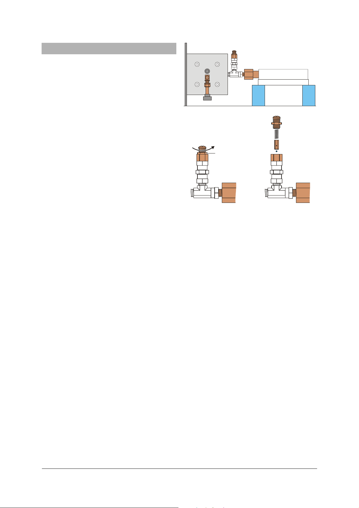
Fig. 7: Ausbau des Sicherheitsventils.
(c) Kontermutter, (d) Ventilkappe, (e) Druckfeder,
(f) Sechskantstempel, (g) Stahlkugel
f
g
Ausbau des Sicherheitsventils:
• Kontermutter (SW 14) des Sicherheitsventils lösen
und Ventilkappe mit einem Schraubendreher
herausdrehen (siehe Fig. 7).
• Nacheinander die Druckfeder, den Sechs-
kantstempel und die Stahlkugel mit einer Pinzette entnehmen und z.B. in einer Schachtel ablegen.
Montage der Öl-Befüll-Vorrichtung:
• Überwurfmutter der Öl-Befüll-Vorrichtung lösen,
Aufsatz abnehmen und Überwurfmutter über das
Sicherheitsventil legen (siehe Fig. 8).
• Öl-Behälter nicht zu fest einschrauben (der O-Ring
darf nicht herausquetschen).
• Regulierventil öffnen.
• Handrad zunächst ganz bis zum Anschlag am
Bügel hineindrehen (ggf. mitdrehende Skala lösen) und danach das Handrad um 3 Umdrehungen herausdrehen.
• Saugfähiges Papier unterlegen und Öl-Behälter
bis maximal zur Hälfte mit Rizinusöl befüllen.
• Aufsatz der Öl-Befüll-Vorrichtung mit der Über-
wurfmutter verschrauben.
Anschluss der Vakuumpumpe:
• Kunststoffschlauch mit 3 mm Innendurchmesser
auf den Gasanschlussstutzen der Apparatur und
den kleineren Stutzen der Öl-Befüll-Vorrichtung
stecken.
• Zum Anschluss der Vakuumpumpe einen Vaku-
10
Page 11
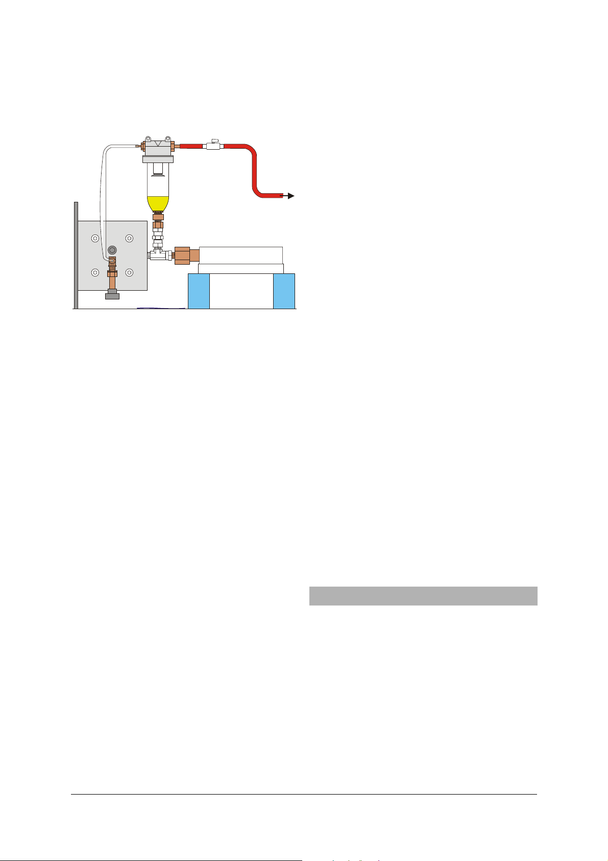
umschlauch mit 6 mm Innendurchmesser über
einen Absperrhahn oder besser über ein Dosierventil an den größeren Stutzen der Öl-BefüllVorrichtung anschließen.
kl
i
h
Fig. 8: Montage der Öl-Befüll-Vorrichtung und Anschluss
der Vakuumpumpe (h) Ölbehälter, (i) Überwurfmutter, (k) Aufsatz, (l) Absperrhahn (bzw. Dosierventil)
Entgasen:
• Kontrollieren, ob das Regulierventil offen und das
Spülventil geschlossen ist.
• Vakuumpumpe einschalten, Absperrhahn wenig
öffnen und dabei die Schaumbildung im Rizinusöl beobachten.
Der Abpumpvorgang ist durch Schließen des Absperrhahns zu unterbrechen, wenn die Schaumbildung so
stark ist, dass der am Aufsatz angebrachte Filter erreicht wird. Erst nachdem der Schaum zerfallen ist,
wird der Absperrhahn wieder geöffnet.
Nach mehreren Minuten (abhängig vom Saugvermögen der angeschlossenen Vakuumpumpe) wird der
Dampfdruck des Rizinusöls erreicht und es beginnt zu
sieden. Dies ist daran zu erkennen, dass „aus dem
Nichts“ Dampfblasen entstehen, die sich auf ihrem
Weg durch das Öl schnell vergrößern.
Jetzt ist das Öl ausreichend entgast.
• Regulierventil und Absperrhahn schließen.
Abbau:
• Vakuumschlauch vom Absperrhahn abziehen (das
Schlauchstück mit dem Hahn verbleibt noch an
der Öl-Befüll-Vorrichtung).
• Zur Vermeidung eines Druckstoßes den Absperr-
hahn langsam öffnen und den Druckausgleich
abwarten.
• Schläuche von beiden Stutzen der Öl-Befüll-
Vorrichtung abziehen.
• Behälter aus dem Sicherheitsventil herausschrau-
ben.
Da das Rizinusöl relativ dickflüssig ist, läuft es nur
sehr langsam aus dem Behälter und dieser Arbeitsgang kann problemlos durchgeführt werden. Ein
Putztuch (Küchenpapier), das direkt nach dem Herausdrehen unter den Behälter gehalten wird verhindert jegliche Tropfenbildung.
• Mit einem Putztuch das überschüssige Öl aus dem
Sicherheitsventil entfernen und danach das
Handrad minimal hineindrehen, bis sich der Ölspiegel im Ventil genau auf der Höhe der Auflagekante der Stahlkugel befindet.
• Stahlkugel einlegen, den Sechskantstempel mit
der kurzen Bohrung auf die Kugel stellen (Pinzette) und die Druckfeder in die längere Bohrung
stecken.
• Ventilkappe vorsichtig (nicht zu fest) bis zum
Anschlag einschrauben und 2 Umdrehungen lösen.
Sicherheitsventil einstellen:
• Apparatur aufrichten und so aufstellen, dass das
Sicherheitsventil nicht in die Richtung von Personen oder zu schützenden Gegenständen zeigt.
• Regulierventil öffnen, Handrad ganz heraus-
drehen und Regulierventil wieder schließen.
• Handrad hineindrehen bis ca. 65 bar Überdruck
erreicht werden.
• Mit den Armen von vorne um die Apparatur her-
um nach hinten zum Sicherheitsventil greifen
und Ventilkappe des Sicherheitsventils langsam
herausschrauben, bis der Druck auf ca. 63 bar abfällt.
• Kontermutter (SW 14) festziehen.
Ruheposition
• Handrad zurückdrehen, bis der Druck auf max.
10 bar gefallen ist.
• Regulierventil öffnen und das Handrad in die
„Ruheposition“ bei ca. 5 mm drehen.
• Regulierventil schließen.
Nach diesen Arbeiten kann die Apparatur eingelagert
oder erneut mit Testgas befüllt werden.
11. Pflege und Wartung der Gewindebuchse
11.1 Gewindebuchse fetten
Etwa alle 100 Zyklen (bestehend aus einer Druckerhöhung von 10 auf 60 bar und der nachfolgenden Entspannung auf 10 bar) bzw. einmal wöchentlich sollte
die Gewindebuchse im Bügel zur Verminderung des
Verschleißes gefettet werden. Das Abschmieren dauert ca. 1 min und verlängert die Buchsen-Lebensdauer
beträchtlich! Zur Abschmierung eignet sich ein helles
Mehrzweckfett ohne Graphit oder ähnliche Zusätze.
Hierzu:
• Einen vollen Kolbenhub Fett aus einer handelsüb-
lichen Fettpresse durch den Schmiernippel am
Bügel in die Gewindebuchse pressen.
11
Page 12

• Das überschüssige, aus der Buchse austretende
Fett abwischen.
Das austretende Fett enthält auch etwas Kunststoffabrieb, der auf diese Weise entfernt wird.
11.2 Gewindebuchse prüfen.
Die Gewindebuchse im Bügel unterliegt einem langsamen aber stetigen Verschleiß und ist daher einmal
jährlich hinsichtlich des Axialspiels zu prüfen:
• Druck aus der Messzelle ablassen und den Kolben
auf Position 10 mm einstellen.
• Mit einer Schieblehre den minimalen und den
maximalen Abstand zwischen Handrad-Flansch
und Bügel bestimmen; dazu gegen das Handrad
drücken und anschließend am Handrad ziehen.
Wenn die Differenz der beiden Abstände größer als
0,3 mm ist, muss die Buchse ausgetauscht werden.
11.3 Gewindebuchse austauschen
Zusätzlich erforderlich:
1 Gewindebuchse aus Dichtungssatz (U10402)
Nach 10 Jahren ist die Gewindebuchse in jedem Fall
auszutauschen, auch wenn die Verschleißgrenze nicht
erreicht ist (bei Prüfstandsversuchen konnte nach
1000 Zyklen kein messbarer Verschleiß [<0,05 mm]
festgestellt werden), da bisher keine verlässlichen
Daten zur Langzeitstabilität des verwendeten Kunststoffes (POM-C) verfügbar sind.
• Druck aus der Messzelle ablassen.
• Feststehende Skala abschrauben.
• Gewindestift im Handradflansch lösen und Hand-
rad abziehen.
• Die vier Schrauben in der Querstrebe des Bügels
lösen und die Querstrebe mit der Gewindebuchse
von der Gewindestange herunterdrehen.
• Schmiernippel abschrauben (SW 7) und mit einem
3-mm-Innensechskantschlüssel den quer in die
Gewindebuchse eingeschraubten Gewindestift um
4 Umdrehungen lösen.
• Mit einem geeigneten Dorn die Gewindebuchse
von der Handrad-Seite aus ausschlagen. Oder alternativ eine Schraube M14 lose in die Buchse
eindrehen und die Buchse durch Schläge auf den
Schraubenkopf austreiben.
• Neue Buchse so ansetzen, dass die Querbohrung
mit dem Schmiernippel fluchtet.
• Buchse im Schraubstock (mit Planbacken oder
geeigneter Beilage) einpressen.
• Gewindestift einschrauben (min. 6,0 mm ver-
senkt) und Schmiernippel einschrauben.
Buchsenmaterial: POM-C = Polyoxymethylen Copolymer
Übermaß (Presspassung): 0,05 – 0,1 mm.
12. Dichtungswechsel
Zusätzlich erforderlich:
1 Sechskant-Winkelschraubendreher (SW 6)
1 Dichtungssatz zu U104001 U10402
bestehend aus
1 hutförmige Gummidichtung,
1 runde Gummidichtung,
1 Gummidichtung 78x78 mm
2
,
4 Kupferdichtscheiben
1 Gewindebuchse
Insbesondere wenn die Apparatur direkter Sonneneinstrahlung ausgesetzt ist, kann es nach einiger Zeit
erforderlich werden, die Hutdichtung oder andere
Dichtungen zu wechseln.
12.1 Zerlegen der Apparatur:
• Ggf. Apparatur abkühlen lassen und Kolben mit
dem Handrad in eine möglichst druckarme Position drehen.
• Testgas über das Spülventil ablassen und Spülven-
til schließen.
• Ggf. Gas-Rohrleitung demontieren.
• Regulierventil öffnen.
• Handrad auf Position 25 mm herausdrehen.
• Apparatur nach rechts kippen und auf einer ge-
eigneten Unterlage auf das Handrad und die Kante der Grundplatte stellen.
• Mit einem Sechskant-Winkelschraubendreher
(SW 6) die vier Schrauben in der Ventilplatte
gleichmäßig über Kreuz jeweils 1/8 Umdrehung
lösen, bis die Vorspannung abgebaut ist.
• Schrauben ganz herausdrehen und entnehmen.
• Kupferdichtscheiben ebenfalls entnehmen.
• Ventilplatte mit steigender Kraft links- und
rechtsherum verdrehen, bis sich die Dichtungen
lösen; dabei nicht am Regulierventil drehen.
• Ventilplatte abnehmen (ggf. klebt die Messzelle
noch an der Platte).
• Wiederum durch Verdrehen die noch verbleiben-
de Dichtung zwischen Messzelle und Zylinder
oder zwischen Messzelle und Ventilplatte lösen.
• Führungsrohr durch Verdrehen von der Hutdich-
tung abziehen.
12.2 Reinigung der zerlegten Apparatur:
Rizinusöl lässt sich relativ gut mit Spiritus entfernen.
Mantel und Messzelle aus Acrylglas werden jedoch
durch Spiritus angegriffen. Fingerabdrücke und sonstige Verschmutzungen können in einer (milden)
Spülmittel-Lösung entfernt werden. Auch die neuen
Dichtungen sollten mit Spiritus und Spülmittel-Lösung
gereinigt werden.
12
Page 13
12.3 Zusammenbau der Apparatur:
Falls Rizinusöl aus dem Ölraum entfernt wurde:
• Neues Rizinusöl bis etwa 5 mm unter die Zylin-
der-Oberkante (Beginn der Senkung) einfüllen.
• Beide Silikondichtungen einlegen.
• Hutdichtung umstülpen und den Zapfen mit
etwas Rizinusöl befeuchtet in das Führungsrohr
eindrehen.
• Hutdichtung zurückstülpen, Feder auf den Kolben
stellen und das Führungsrohr in den Kolben stecken.
• Messzelle auflegen und an den Kanten des Zylin-
ders gleichmäßig ausrichten.
• Temperiermantel auf die untere Silikondichtung
stellen und zentrieren.
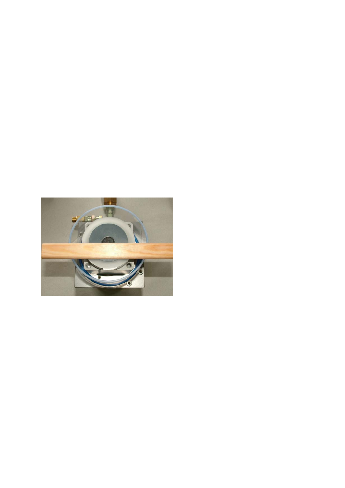
• Runde Gummidichtung auflegen und mit Hilfe
eines Lineals, das auf den Temperiermantel gelegt wird, parallel zum Zylinder ausrichten (vgl.
Fig. 9, die halbmondförmigen Löcher müssen sich
später unter den Ventilöffnungen befinden).
Fig. 9: Ausrichten der runden Gummidichtung
• Ventilplatte auflegen, zentrieren und parallel zur
Basisplatte ausrichten.
• Schrauben M8×40 mit neuen Kupferdichtschei-
ben versehen und lose eindrehen.
• Schrauben über Kreuz festziehen; dabei die
gleichmäßige Pressung der runden Gummidichtung kontrollieren (im Bereich hoher Pressung zeichnet sich die Gummidichtung auf dem
Acrylglas der Messzelle grau ab, während Bereiche mit geringer Pressung milchig erscheinen).
12.4 Wiederinbetriebnahme:
• Hydrauliköl entgasen und Öl einfüllen (siehe Ab-
schnitt 10).
• Sicherheitsventil einstellen (siehe Abschnitt 10).
• Volumenkalibrierung neu durchführen (siehe Ab-
schnitt 6).
3B Scientific GmbH • Rudorffweg 8 • 21031 Hamburg • Deutschland • www.3bscientific.com
Technische Änderungen vorbehalten
© Copyright 2010 3B Scientific GmbH
Page 14

Page 15
1
3B SCIENTIFIC
Critical Point Apparatus U104001
Instruction sheet
09/10 MH/JS
23
22
19
18
17
®
PHYSICS
1 Vernier scale
2 Fixed scale
3 Grease nipple
4 Threaded bush
5 Handwheel
6 Base
7 Frame
8 Threaded axle with piston
9 Piston cover
10 Outlet for thermal medium
11 Inlet for thermal medium
12 End plate
13 Cylinder
14 Conical seal
1220 21
3 4
15 Measuring cell
16 Valve plate
17 Regulating valve
18 Gas connection fittings 1/8"
(for Minican® gas container)
19 Flush valve
20 Hole for thermocouple
5
21 Heat casing
22 Safety valve
23 Manometer (excess pressure indicator)
876
On delivery, the critical point apparatus is filled with
hydraulic fluid. The test gas is not included.
Before filling with the test gas, carry out a volume
calibration, as described in chapter 6, using air as an
approximation of an ideal gas.
Filling with the test gas is described in chapter 7.
Experimental investigations are described in chap-
ter 8.
Important notes on storage of the test gas and
equipment (if not in use for a long period) are stated
in chapter 9.
1516 14
1213
91
1. Contents of instruction manual
Owing to the inevitable diffusion of the test gas
through the conical seal, it is necessary to degas the
hydraulic fluid in the equipment, as described in
chapter 10. This must be done before the equipment
is put away for storage (after removing the test gas) or
if it has been in use for a long time.
The threaded bush in the frame must be lubricated
regularly and also inspected at lengthier intervals.
Refer to section 11 for instructions.
Maintenance work as described in chapter 12 is only
required if the rubber components get worn out and
their functionality is adversely affected.
1
Page 16

2. Safety instructions
3. Description
When used properly, the operation of the critical
point apparatus is not dangerous, since both the
experimenter and the equipment are protected by a
safety valve. However, it is extremely important to
observe a few precautionary measures:
• Read the instruction sheet thoroughly and follow
the instructions therein.
• Do not exceed the maximum permissible values
for pressure and temperature (60 bar and 1060°C).
• Do not operate the equipment without qualified
supervision.
• Always wear safety goggles.
Only increase the temperature at low pressure with
pure gas phase in the measuring cell.
• Before increasing the temperature, wind the
handwheel outwards so that maximum volume is
attained in the measuring cell.
When conducting adjustments, make sure that the
safety valve does not point in the direction of people
who could be injured or objects that could be damaged if the valve cover shoots out. When conducting
experiments, pay special attention too to the alignment of the safety valve.
• When setting up the apparatus, make sure that
the safety valve does not point in the direction of
people who could be injured or objects that could
be damaged.
• When adjusting the safety valve, wrap your arms
around the apparatus to reach the valve at the
back.
If the conical seal is overtaxed, it could get damaged
or even destroyed.
• Never set a pressure above 5 bar if the regulating
valve or the flush valve is open, i.e. if there is no
back pressure from the gas in the measuring cell.
• Never create underpressure by turning the hand
wheel inwards when the valves are shut.
In the frame there is a threaded bush, which is to be
regarded as a safety-related feature (see section 9).
• Lubricate the threaded bush every 100 cycles.
• Inspect the threaded bush annually.
To prevent damage by corrosion inside the instrument,
• use a 2:1 mixture of water and anti-freeze fluid as
the thermal medium.
The critical point apparatus allows us to investigate
the compressibility and liquefaction of a gas. Measurements allow determination of the critical point for
the gas as well as the recording of isotherms for an
adiabatic p-V diagram (Clapeyron diagram). The gas
used for testing is sulphur hexafluoride (SF
). SF6 has a
6
critical temperature of 318.6°K (45.5°C) and a critical
pressure of 3.76 MPa (37.6 bar) which makes for a
simple experiment set-up.
The critical point apparatus consists of a transparent
measuring cell of particularly well sealed, pressureresistant design. The volume of the measuring cell
can be modified by turning a fine-adjustment wheel
and can be read by means of a fixed scale and a rotating vernier scale to an accuracy of one thousandth of
the maximum volume. The pressure is applied via a
hydraulic system using castor oil approved for medicinal use. The measuring cell and hydraulic system
are isolated from one another by a conical rubber
seal which rolls up when there is an increase in pressure. This design means that any pressure difference
between the measuring cell and the oil reservoir is
negligible in practical terms. A manometer measures
not the pressure of the actual gas but that of the oil,
thus eliminating any need for a space within the
measuring cell. When observing transitions from gas
to liquid or vice versa, the lack of such a dead space
means that the development of the very first drop of
liquid as well as the disappearance of the last bubble
of gas can be observed. The measuring cell is surrounded by a transparent chamber of water. A circulating thermostat arrangement (water bath) means
that a constant temperature can be maintained during the experiment with a high degree of accuracy.
The temperature can be read and monitored using a
thermometer.
The fact that volume, pressure and temperature can
all be read with a high degree of accuracy means that
accurate p-V diagrams or pV-p diagrams can be recorded without much difficulty. Pressure and temperature-dependent volume correction enable us to
achieve accurate quantitative results which are well in
agreement with published values.
4. Contents
1 Critical point apparatus, filled with hydraulic fluid
(castor oil). With attached gas connection fittings
for MINICAN® gas container and protection for gas
supply connections. Test gas (SF
) not included.
6
1 Oil filling device
1 Allen key, 1.3 mm (for grub screw on the vernier
scale)
1 Plastic tubing, 3 mm diameter
1 1/8" tube fitting (wrench width 11 mm)
1 Grease gun
2
Page 17

A
J
Δ⋅=
Δ
5. Technical data
Sulphur hexafluoride:
Critical temperature: 318.6 K (45.5°C)
Critical pressure: 3.76 MPa (37.6 bar)
Critical volume: 197.4 cm
3
/mol
Critical density: 0.74 g/mol
Maximum values:
Temperature range: 10-60°C
Maximum pressure: 6.0 MPa (60 bar)
Threshold value for
safety valve: 6.3 MPa (63 bar)
Theoretical long-term
pressure: 7.0 MPa (70 bar)
Theoretical rupture
pressure: >20.0 MPa (200 bar)
Materials:
Test gas: Sulphur hexafluoride (SF
)
6
Hydraulic fluid: Castor oil
Measuring cell: Transparent acrylic
Temperature coating: Transparent acrylic
Recommended
thermal medium: mixture of water and anti freeze in the ratio 2:1
Determination of volume:
Piston diameter: 20.0 mm
Piston surface: 3.14 cm
Displaced volume: 3.14 cm
Maximum volume: 15.7 cm
2
2
× displacement
3
Scale division for
displacement: 0.05 mm
Maximum displacement: 50 mm
Determination of pressure:
Manometer: Class 1.0 (max. 1% deviation
from full scale value)
Measured quantity: Excess pressure
Indicator: 60 bar max.
Manometer diameter: 160 mm
Connections:
Hole for
temperature sensor: 6 mm dia.
Connections for
thermal medium: 7 mm dia.
Connection for
regulating valve: 1/8’’ dia.
Gas connection: 1/8’’ (3.17 mm) dia. (as
supplied)
General specifications:
Dimensions: 380 x 200 x 400 mm
3
Weight: 7 kg approx.
6. Volume calibration
6.1 Preliminary notes:
NOP M
Q
L
K
R
S
B C E F
Fig. 1: Cross-section of apparatus with measuring cell (A),
conical seal (B), oil chamber (C), piston (D), cylinder (E), heat casing (F), silicone seal (G), end
plate (H), square grommet (I), piston cover (J),
threaded axle (K), gasket (L), manometer connection (M), guide tube (N), spring (O), sleeve (P), hole
for temperature sensor (Q), circular grommet (R) and
valve plate (S)
D
I
H
G
One turn of the handwheel winds the piston into/out
of the cylinder by means of a threaded axle. This
leads to a change of volume in the oil chamber (see
Fig. 1). Since oil is practically incompressible and all
the other components other than the conical seal are
almost rigid, a change in volume in the oil chamber
causes the conical seal to deform, thereby creating an
almost equal change in volume ΔV
cell. As a first approximation for ΔV
sAV
G
where
(1)
2
cm143.A= and Δs = displacement of piston.
in the measuring
G
, we can assume:
G
The piston displacement is shown in divisions of
2 mm on the fixed scale. Intermediate values are read
on the vernier scale in divisions of 0.05 mm.
The fixed scale can be moved by loosening the two
knurled screws. The vernier scale can be repositioned
and turned around the threaded axle on loosening
the grub screw (between scale positions 0 9 and 1 0).
6.2 Zero point calibration:
The zero point for the volume scale must be determined by conducting a calibration.
For this, we take advantage of the fact that in a pressure range of 1-50 bar and in a temperature range of
270-340 K, air acts as a near-ideal gas (the real gas
factor has a deviation of less than 1% from 1). Therefore, at a constant temperature (e.g. room temperature) for two piston displacements s
and s1 and for
0
3
Page 18
the corresponding pressures p0 and p1 of the trapped
T
⋅
⋅
=
air, we get:
spsp ⋅=⋅ (2)
1100
Substituting
p
s Δ⋅
1
0
=
pp
−
s
01
sss Δ+=
10
and rearranging gives:
(3)
Rough calibration of scales:
• Open the regulating valve wide.
• Loosen the grub screw for the vernier scale by
half a turn (it is now possible to turn the scale
easily on the threaded axle without moving the
handwheel, although a counterpressure acts
against this independent movement).
• Wind the handwheel out till you detect a notice-
able resistance.
• Without turning the handwheel, turn the vernier
scale on the threaded axle till the 0.0 mark is on
the top and the fixed scale shows approx. 48 mm.
• Loosen the knurled screws of the fixed scale and
shift the scale to the side till the 48-mm bar is exactly above the centre line of the vernier scale
(see Fig. 2).
• Tighten the knurled screws again. In doing so,
make sure that the fixed scale does not press
against the vernier scale.
100 20304050mm
00
19
18
17
• Calculate the zero corrected piston position s
1, corr
using Equation 3.
• Adjust the vernier scale to the corrected value
and, if necessary, move the scale again.
• If required, wind the handwheel out a little and
secure the vernier scale with the grub screw.
Measurement example:
= 1 bar, p1 = 16 bar, p1 – p0 = 15 bar
p
0
s
= 48.0 mm, s1 = 3.5 mm, Δs = 44.5 mm
0
Therefore,
s
= 2.97 mm.
1, corr
The vernier scale must therefore be adjusted so that
now only 2.97 mm are shown instead of 3.50 mm.
Note:
After calibrating the zero point, it is possible to obtain
qualitatively accurate measured values. With regard
to temperature
T and pressure p, it is also possible to
obtain quantitatively accurate measurements of the
isotherms in range around to the critical point where
the two phases exist simultaneously. However, especially in the liquid phase, the measured isotherms are
rather too widely separated.
6.3 Detailed calibration:
The exact relation between the volume VG in the
measuring cell and the scale reading
s is dependent
on the volume of oil in the oil chamber. The oil
chamber also expands marginally in proportion to the
pressure as a result of the spring in the manometer
tube. Additionally, when the temperature is increased, the castor oil expands to a greater extent
than the rest of the equipment. This means that the
pressure rises at a slightly greater rate at higher temperatures. All of these phenomena can be calculated
if appropriate calibration has been effected using air
as an ideal gas.
The ideal gas equation would thus be:
Vp
Rn
(4)
⋅=
16
with
J
3148.R =
molK
Fig. 2: Piston position reading at 48.0 mm
Zero correction:
• Shut the regulating valve (the pressure in the
measuring cell now corresponds to the ambient
pressure
p
= 1 bar. To within the accuracy of the
0
measurement, the manometer should display an
excess pressure of 0 bar).
• Wind the handwheel in till an excess pressure of
15 bar has been reached (absolute pressure
p
= 16 bar).
1
• Read the piston position s
displacement
Δs = s
– s1.
0
and calculate the
1
After taking the overpressure reading
pressure can be calculated from:
p = p
+ 1 bar (6)
e
The absolute temperature is given by:
T = ϑ + ϑ
where ϑ0 = 273.15°C (7)
0
The volume is given by:
sAV
G
where
(8)
2
cm143,A = and s is the “effective” piston
displacement.
From the measured displacement
p
, the absolute
e
s
, it is possible to
e
calculate the effective piston displacement as follows:
4
Page 19

(9)
(
)
ϑ⋅−⋅++=
CpCsss
pe 0
ϑ
By substituting in equation 4, we get:
⋅ϑ⋅β−⋅β++⋅
0
pe
ϑ+ϑ
0
Apssp
ϑ
(10)
0
=⋅−
Rn
If we take several readings at various temperatures
and pressures, we can calculate the term:
n
()
⎛
⎜
Q
=
∑
⎜
=
1i
⎝
The free parameters s
Apssp
⋅ϑ⋅β−⋅β++⋅
p
, βP, βϑ and n should be appro-
0
ϑ
ii0ii
ϑ+ϑ
0
2
⎞
⎟
Rn
(11)
⋅−
⎟
⎠
priately selected so that the value of Q is reduced to a
minimum.
Additionally required (see also chapter 8):
1 Compressor or
bicycle pump and valve
1 Bath/circulating thermostat U14400
1 Dig. quick-response pocket thermometer U11853
1 Type K NiCr-Ni immersion sensor,
-65°C-550°C U11854
2 Silicone tubes, 1 m U10146
1 l Anti-freeze fluid with corrosion-inhibiting additive
for aluminium engines (e.g., Glysantin® G30 manufactured by BASF)
Conducting the calibration:
• Connect the circulation thermostat as described
in chapter 8 and fill it with the water/anti-freeze
mixture.
• Connect the plastic tube (3-mm internal diameter)
to the 1/8" gas connection fittings.
• Open the regulating valve.
• Wind the handwheel outwards, making the piston
move till it reaches say the 46.0 mm position.
• Use a compressor or a bicycle pump to create an
excess air pressure of approx. 3-8 bar in the
measuring cell.
• Shut the regulating valve.
• To record measurements, vary the volume in the
measuring cell or the temperature of the thermostat and wait till a stationary equilibrium has
been attained. Then take a pressure reading.
• Use appropriate adjustment software to set the s
, βϑ and n parameters so that the quadratic
β
P
,
0
equation for the errors Q is reduced to a minimum (see equation 11).
• If you like, you can adjust the vernier scale
around s
so that this correction is not necessary.
0
With the set parameters, it is possible to calculate the
“effective” piston displacement s from the measured
displacement s
using Equation 9 and then to calcu-
e
late the calibrated measuring cell volume using Equa-
tion 8.
Sample measurements:
Table 1: Measured values for calibration
i s
/ mm
e
ϑ
p / bar
1 40.0 20.0°C 6.6
2 20.0 20.0°C 12.4
3 10.0 20.0°C 23.3
4 5.0 20.0°C 41.8
5 3.5 20.0°C 53.9
6 5.0 20.0°C 41.8
7 5.0 10.0°C 38.9
8 5.0 30.0°C 45.3
9 5.0 40.0°C 49.0
10 5.0 50.0°C 53.5
The following parameter values are obtained:
s
= 0.19 mm,
0
P
mm
.=β ,
0230
bar
ϑ
mm
grd
and
0340.=β
n = 0.00288 mol.
7. Filling with test gas
7.1 Handling of sulphur hexafluoride:
Sulphur hexafluoride (SF6) is a non-toxic gas and is
absolutely safe for humans. The MAC value for danger
of suffocation on account of oxygen deprivation is
1000 ppm. That is equivalent to 6 filled measuring
cells per 1 m
However, SF
3
of air.
is extremely harmful to the environment
6
and can give rise to a greenhouse effect 24,000 times
stronger than CO
. Therefore, do not allow large quan-
2
tities to be released into the environment.
7.2 Gas connection via fixed pipes:
Additionally required:
1 SF
gas cylinder with manufacturer’s/supplier’s rec-
6
ommended gas fittings/valves, e.g. SH ILB gas cylinder
and Y11 L215DLB180 regulating valve from Airgas
(www.airgas.com).
1 Pipes with outer diameter of 1/8" and, if necessary,
adapters, e.g. from Swagelok (www.swagelok.com).
1 open-end spanner (13 mm), 1 open-end spanner
(11 mm)
According to the principles of “good laboratory practice”, it is recommended to utilise a gas supply via
fixed pipes, especially if the equipment is regularly in
operation.
5
Page 20
Filling begins with several flush cycles in which the air
m
m
is flushed out of the pipe. The number of cycles required to flush out the air depends on the length of
the pipe (more precisely, on the ratio of the pipe
length to the volume of the measuring cell). In the
process, care should be taken that the quantity of the
greenhouse gas SF
released in the environment is
6
reduced to a minimum.
Connecting a fixed pipe:
100 20304050m
00
19
18
17
16
15
ab
Fig. 3: Connecting a fixed pipe
(a) flush valve, (b) regulating valve
• If necessary, pull out the protection for the gas
connection and loosen the valve nut (11 mm) to
remove the 1/8" gas connection fittings.
• Connect the pipe (if necessary with adapters) to
the gas fitting.
• Beginning with the valve nut, slide the supplied
screw joints onto the tubing. (See Fig. 3: follow
the sequence and alignment specified along with
the cable binder)
• Insert the pipe into the regulating valve and
tighten the valve nut till the point is reached
where it is no longer possible to move the pipe
any further using only your fingers.
• Hold the regulating valve still with an open-end
spanner (13 mm) and tighten the valve nut by a
further 270°.
Now, the connection is gas-tight. When loosening the
valve nut afterwards, the regulating valve also needs
to be held still with a spanner.
Flushing out air:
• Use the handwheel to set the piston position to
10 mm.
• Slowly open the regulating valve and let in the SF
till a pressure of approx. 10 bar has been attained.
• Shut the regulating valve.
• Open the flush valve slightly till the pressure has
dropped to almost 0 bar.
• Shut the flush valve.
Filling with test gas:
• After at least four flush cycles, open the regulat-
ing valve till the pressure attained is once again
10 bar.
• Shut the regulating valve.
• Turn the handwheel in the reverse direction till
the piston reaches a position of say 46 mm.
• Slowly open the regulating valve and shut it again
when a pressure of 10 bar has been attained.
7.3 Filling with gas from a MINICAN®:
Additionally required:
1 MINICAN® gas container with SF
, e.g. from the
6
company Westfalen (www.westfalen-ag.de
If the equipment is used only occasionally, it is more
practical to draw the test gas from a MINICAN® gas
container. The gas connection of a MINICAN® container is similar in design to a commercial spray can,
i.e. it opens when the MINICAN® container is pressed
directly onto the gas connection fittings.
Here too, filling begins with several rinsing cycles for
flushing out the air.
SF
6
ab
Fig. 4: Filling with test gas from a MINICAN® gas container
(a) flush valve, (b) regulating valve
Flushing out air:
• If necessary, pull off the protection for the gas
connection.
• Use the handwheel to set the piston position to
10 mm.
• After removing the protective cap, position the
6
MINICAN® container with SF
onto the gas connec-
6
tion fittings.
• Press the MINICAN® container onto the gas con-
nection fittings, slowly open regulating valve (b)
100 20304050m
00
19
18
17
16
15
6
Page 21

and let in SF6 till a pressure of approx. 10 bar has
been attained.
• Shut the regulating valve.
• Open the flush valve slightly till the pressure has
dropped to almost 0 bar.
• Shut the flush valve.
Filling with test gas:
• After at least four flush cycles, press the MINI-
CAN® gas container against the gas connection fittings. Slowly open the regulating valve and let in
SF
till a pressure of approx. 10 bar has been at-
6
tained.
• Shut the regulating valve.
• Wind the handwheel in the opposite direction till
the piston reaches a position of say 46 mm.
• Press the MINICAN® gas container against the gas
connection fittings, slowly open the regulating
valve and shut it again when a pressure of 10 bar
has been attained.
7.4 Recommendation for storage lasting for short
periods of time:
One gas filling can remain in the measuring cell for
several days.
If no experiments are being conducted, wind the
handwheel back till the piston is in a position where
it is subjected to the lowest possible pressure – say,
for instance, 46 mm.
If possible the apparatus should always be kept filled
with the thermal medium.
8. Experiments
8.1 Experiment set-up:
Additionally required:
1 Bath/circulating thermostat U14400
1 Dig. quick-response pocket thermometer U11853
1 Type K NiCr-Ni immersion sensor,
-65°C-550°C U11854
2 Silicone tubes, 1 m U10146
1 l Anti-freeze fluid with corrosion-inhibiting additive
for aluminium engines (e.g., Glysantin® G30 manufactured by BASF)
• Place the equipment at a suitable height so that it
is convenient to observe the measuring cell. Position it so that the safety valve does not point in
the direction of any people who could be injured
or objects that could be damaged.
• Connect the silicone tubing from the outlet of the
circulation thermostat to the inlet of the heat casing and from the outlet of the heat casing to the
inlet of the circulation thermostat.
• Prepare the thermal medium consisting of 2 parts
water to 1 part anti-freeze by volume.
• Fill the circulated thermostat bath.
8.2 Qualitative observations:
Liquid and gaseous states, dynamic state during phase
transformation, transition points occurring at different temperatures.
• Vary the volume by turning the handwheel and
the temperature by means of the thermostat. Observe the safety instructions while doing so.
• Carefully shake the set-up to conduct simple
observations on the boundary between liquid and
gas.
In the vicinity of the critical point, it is also possible to
observe the critical opalescence. Owing to the constant changing of state between liquid and gaseous
states in small regions of the measuring cell, a kind of
“mist” develops and the sulphur hexafluoride appears
to be turbid.
8.3 Measuring isotherms in a p-V diagram:
• At maximum volume, set the desired temperature
on the circulation thermostat.
• Gradually reduce the volume in the measuring
cell (in steps down to a position of 10 mm). Wait
till a stationary equilibrium has been attained before taking pressure readings.
• Then, beginning with the minimum volume,
gradually increase the volume till the piston position is once again at 10 mm. Wait till a stationary
equilibrium has been attained before taking pressure readings.
• Convert the excess pressure readings into abso-
lute pressure and the piston positions into volume, as described in chapter 6.
In the low-volume region, stationary equilibrium is
attained more quickly during transition from higher
to lower pressure – i.e. from a lower volume to a
greater volume – since the phase boundary layer for
the phase transition from liquid to gas is created by
vapour bubbles present throughout the liquid. Stationary equilibrium then takes around 1 to 5 minutes
to attain, whereby the measurements on the fringe of
the region where both phases exist take longest.
The recommended threshold value of 10 mm refers to
a filling pressure of 10 bar. Above this value, there
will certainly be no occurrence of a liquid phase in
the permissible temperature range. The threshold
value shifts to the “right” if the filling pressure is
higher.
8.4 Measuring isochores in a p-T diagram:
• Set the desired initial temperature. Subsequently
set the desired volume.
• Gradually allow the temperature to decrease.
• Wait till a stationary equilibrium has been at-
tained then take the pressure reading.
Measurements where both phases are present can be
plotted to generate a vapour-pressure curve.
Attainment of equilibrium takes up to 20 minutes
after each change of temperature due to the fact that
7
Page 22

the water bath and the measuring cell must attain the
desired temperature first.
8.5 Determining the mass of gas:
Blow the gas out of the measuring cell into a gas-tight
plastic bag and then weigh it:
• If necessary, remove the gas supply pipe and
attach gas connection fittings.
• Wind out the handwheel, say to 46 mm.
• Open the regulating valve a little and release the
gas through the gas connection fittings into the
plastic bag.
• Shut the regulating valve.
• Determine the mass of the released gas. In doing
this, take into consideration the empty weight of
the bag and the buoyancy of air.
• Reduce the volume of the measuring cell till the
pressure in the measuring cell has reached its
original value.
• Calculate the original mass of gas from the vol-
ume difference before and after emptying the
measuring cell and the volume which is still present in the measuring cell.
Comparison with quoted values:
Using tabulated values, e.g. Clegg et al. [4], it is alternatively possible to calculate the mass of gas in the
measuring cell from the measurements of ϑ, p, and V.
8.6 Evaluation:
We can clearly see from Fig. 5 that, despite the relatively simple equipment, it is possible to achieve
measurements which match closely to the reference
values plotted on the graph.
8.7 Bibliography:
[1, 2] Sulphur Hexafluoride, in-house publication,
pp. 27 [1], 30 [2], Solvay Fluor und Derivate GmbH,
Hannover, Germany, 2000
[3] Otto and Thomas: Landolt-Börnstein – Numerical
Data and Functional Relationships in Science and
Technology, Vol. II, Section 1, Springer-Verlag, Berlin,
1971
[4] Clegg et al.: Landolt-Börnstein – Numerical Data
and Functional Relationships in Science and Technology, Vol. II, Section 1, Springer-Verlag, Berlin, 1971.
[5] Din, F.: Thermodynamic Functions of Gases, Vol. 2,
Butterworths Scientific Publications, London, 1956
[6] Vargaftik, N.B.: Handbook of Physical Properties of
Liquids and Gases, 2
nd
ed., Hemisphere Publishing
Corporation, Washington, 1983
[7] Nelder, J. and Mead, R.: Comp. J., Vol. 7, p. 308,
1965
9. Storage for long periods without use
If no experiments are to be conducted over a long
period, the test gas should be released and the piston
should be turned to its rest position where the conical
rubber seal is only very slightly curled and does not
press against the walls of the measuring cell.
• If necessary, allow the equipment to cool. Wind
the handwheel back till the lowest possible pressure is present.
• Release the test gas through the flush valve.
• Turn the handwheel to move the piston to its
“rest position”, at approx. 5 mm.
• Shut the flush valve again.
• Before storing away the equipment, the hydraulic
fluid needs to be degassed (as described in chapter 10) if the equipment has been in use over a
long period of time.
• Store the equipment in a safe place where it is
not exposed to direct sunlight.
• The thermal medium should be kept in the appa-
ratus during storage, as the additives inhibit corrosion and efflorescence caused by electrochemical potentials between the different materials. Alternatively, the apparatus can be flushed with deionised water and then dried using compressed
air (oil-free, max. 1.1 bar).
8
Page 23
1
p
/ MPa
5
4
3
2
1
0
0
Fig. 5: p-V diagram of SF6, measured with the critical point apparatus:
Readings taken at 10°C (
(
Reference values from [2] for pressure of liquid at 10°C (
and 50°C (
246 81012
V
/ ml g
), 20°C ( ), 30°C ( ), 40°C ( ), 45°C ( ) and 50°C ( ),
) threshold value of liquid-gas mixture, ( ) Reference values from [1] for vapour pressure,
), 20°C ( ), 30°C ( ), 40°C ( )
)
9
-
Page 24

10. Degassing the hydraulic fluid
Owing to the inevitable diffusion of the test gas
through the protection valve, the pressure in the
measuring cell slowly decreases over a long period.
The gas diffusing through the protection valve first
dissolves in the hydraulic fluid but does not have any
significant influence on the measurements.
However, if the test gas is removed from the equipment (for storage of the equipment) and the pressure
of the hydraulic fluid consequently falls to the ambient pressure, then the test gas will escape from the
hydraulic fluid due to Henry's law. This leads to a
gradual increase in pressure in the oil chamber which
must be avoided at all costs as there is no back pressure in the measuring cell. On account of this, it is
necessary to cleanse the hydraulic fluid of all gas
before storing the equipment.
To degas the hydraulic fluid, the oil is made to boil in
a vacuum. Since the pressure difference on both sides
of the protection valve should not exceed a particular
limit, it is necessary to maintain, as best as possible,
the existing underpressure constant on the gas side.
Additionally required:
1 Castor oil approved for medicinal use e.g. U10401
1 Vacuum tube, 6 mm internal diameter
1 Stopcock (or variable-leak valve)
1 Vane-type rotary pump
1 Open-end spanner (14 mm), 1 pair of tweezers
Absorbent paper, cardboard box
Storage of the equipment:
• If necessary, allow the equipment to cool. Wind
the handwheel back till the lowest possible is present.
• Release the test gas through the flush valve and
shut the flush valve thereafter.
• If necessary, remove the gas supply pipe and
attach the gas connection fittings.
• Unscrew the vernier scale.
• Open the regulating valve.
• Wind the handwheel so that piston moves in till
an excess pressure of 1 bar has been attained.
• Shut the regulating valve.
• Wind the handwheel back by two turns.
• Place the equipment with the manometer facing
downwards towards the ground). The manometer
should rest on a support approx. 6-cm-thick (see
Fig. 6).
Caution: the piston should never be wound out to
more than 25 mm, since the guide tube may slip out
during subsequent operations.
Fig. 6: Storage of the equipment for oil filling
c, d
e
d
c
Fig. 7: Dismantling the safety valve
(c) counter nut, (d) valve cap, (e) compression spring,
(f) hexagonal piston, (g) steel ball bearing
f
g
Dismantling the safety valve:
• Loosen the counter nut (14 mm) and use a screw-
driver to remove the valve cap (see Fig. 7).
• Remove the compression spring, the hexagonal
piston and the steel ball bearing in succession
with a pair of tweezers and store them in a safe
place, for instance in a cardboard box.
Assembly of the oil filling device:
• Loosen the valve nut of the oil filling device, re-
move the cover and place the valve nut above the
safety valve (see Fig. 8).
• Do not screw the oil filling device on too tight (the
gasket ring should not be squeezed out).
• Open the regulating valve.
• Wind the handwheel inwards to its end position
up to the frame (if necessary, loosen the vernier
scale). Subsequently wind the handwheel out by 3
turns.
• Place absorbent paper underneath and fill the oil
container with castor oil to no more than half
way.
• Screw on the cover of the oil filling device with
the valve nut.
Connection of vacuum pump:
• Connect a plastic hose with 3 mm internal diame-
ter to the gas connection fittings of the equipment and the smaller connector of the oil filling
device.
10
Page 25
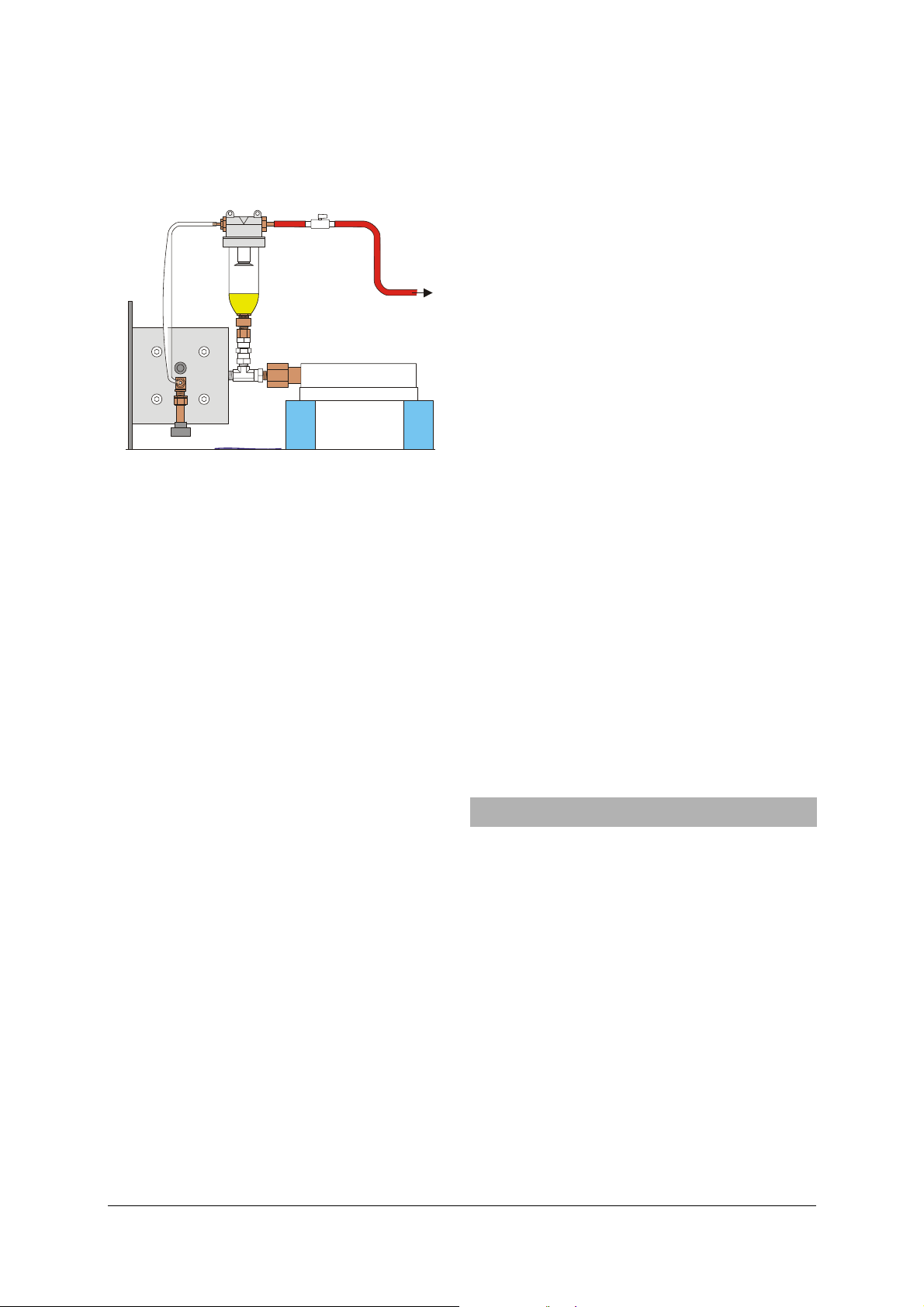
k
l
• In order to connect the vacuum pump, take a
vacuum hose with 6 mm internal diameter and
connect it via a stopcock or preferably via a threeway valve to the larger connector of the oil filling
device.
i
h
Fig. 8: Assembly of the oil filling device and connection of
vacuum pump (h) oil container, (i) valve nut,
(k) cover, (l) stopcock (or variable-leak valve)
Degassing:
• Check whether the regulating valve is open and
the flush valve is shut.
• Switch on the vacuum pump. Open the stopcock a
little and observe the formation of bubbles in the
castor oil.
Close the stopcock to interrupt the evacuation process
if the formation of bubbles is so strong that they can
reach the filter that is mounted on the cover. The
stopcock may be opened only after the bubbling has
subsided.
After at least 15 minutes (depending on the suction
capacity of the connected vacuum pump), the vaporising pressure of the castor oil is attained and the oil
begins to boil. This can be noticed when vapour bubbles begin to form “out of the blue” and rapidly become larger in size as they move through the oil.
The oil is now is sufficiently degassed.
• Shut the regulating valve and the stopcock.
Dismantling:
• Pull out the vacuum hose from the stopcock (the
hose fitting with the stopcock continues to remain on the oil filling device).
• To avoid any surges, slowly open the stopcock
and wait for the pressure to even out.
• Pull out the hoses from both of the connectors on
the oil filling device.
• Unscrew the container from the safety valve.
Since castor oil is relatively viscous, it trickles out of
the container very slowly. Thus, this step can be conducted easily. A cleaning cloth (or kitchen paper)
which is held below the container immediately after
unscrewing it prevents any drops forming.
• With a cleaning cloth, remove excess oil from the
safety valve and subsequently wind the handwheel inwards very slightly till the oil level in the
valve is exactly at the same level as the edge
where the steel ball bearing sits.
• Insert the steel ball bearing, position the hexago-
nal piston with the short bore onto the ball bearing (use tweezers for this) and insert the compression spring into the longer bore.
• Carefully screw the valve cap on in its end posi-
tion (not too tight) and loosen it by two turns.
Positioning the safety valve:
• Set-up the equipment and place it in a way that
the safety valve does not point in the direction of
people who could get injured or objects which
could get damaged.
• Open the regulating valve. Wind the handwheel
fully out and shut the regulating valve again.
• Turn the handwheel in till an excess pressure of
approx. 65 bar has been attained.
• From the front, wrap your arms around the appa-
ratus to reach the safety valve located at the back.
Slowly unscrew the valve cap of the safety valve
till the pressure drops to approx. 63 bar.
• Tighten the counter nut (14 mm).
Rest position:
• Wind the handwheel back till the pressure has
dropped to max. 10 bar.
• Open the regulating valve and turn the hand-
wheel to its “rest position” at approx. 5 mm.
• Shut the regulating valve.
After completing these steps, the equipment can
either be stored or refilled with test gas.
11. Upkeep and maintenance of threaded bush
11.1 Lubricating the threaded bush
To minimise wear, the threaded bush in the frame
should be lubricated approximately every 100 cycles
(one cycle = a pressure increase from 10 to 60 bar and
the subsequent reduction to 10 bar), or once weekly.
Lubrication only takes about 1 min and extends the
service life of the bush significantly. For lubrication, a
light-coloured multi-purpose grease with no graphite
or similar additives is recommended.
Procedure:
• Inject one full stroke of lubricant from a conven-
tional grease gun into the threaded bush through
the nipple at the frame.
• Wipe up any surplus lubricant emerging from the
bush.
When it emerges, the lubricant will also pick up any
traces of plastic that might have worn off during operation, so that will be flushed out too.
11
Page 26

11.2 Examine threaded bush.
The threaded bush in the frame is subject to slow but
constant wear, and therefore the axial play must be
checked once a year:
• Release the pressure from the measuring cell and
adjust the piston to the 10 mm position.
• Using a vernier caliper, determine the minimum
and maximum distance between the handwheel
flange and frame; to do so, first wind in the
handwheel and then wind it out.
If the two distances differ by more than 0.3 mm, then
the bush needs to be replaced.
11.3 Replacing the threaded bush
Additionally required:
1 Threaded bush from set of seals (U10402)
The threaded bush is to be replaced no later than
every ten years even if the limit of wear has not been
reached (tests on a rig failed to produce any measurable wear [<0.05 mm] after 1000 cycles), because
reliable data on the long-term stability of the plastic
used (POM-C) are not yet available.
• Depressurise the measuring cell.
• Unscrew the fixed scale.
• Undo the grub screw of the handwheel flange and
remove handwheel.
• Loosen the four screws in the cross piece of the
frame and remove it along with the threaded
bush by winding it down the axle.
• Unscrew the lubricating nipple (size SW 7) and use
a 3-mm Allen key to loosen the threaded pin
screwed in across the threaded bush by 4 turns.
• Knock the threaded bush out from the side of the
handwheel using a suitable mandrel. Alternatively insert an M14 screw loosely into the bush
and force the bush by hitting the head of the
screw.
• Fit the new bush such that the cross piece is
aligned with the lubrication nipple.
• Clamp the bush in a vice (with flat jaws or suit-
able insert).
• Screw back in the threaded pin (min. 6.0 mm
countersunk) and the lubricating nipple.
Bush material: POM-C = Polyoxymethylene copolymer
Oversize (press fit): 0.05 – 0.1 mm.
12. Changing the seals
Additionally required:
1 Allen key (6 mm)
1 Set of seals for critical point apparatus U10402
consisting of
1 Conical seal,
1 Circular grommet,
1 Grommet 78x78 mm
2
,
4 Copper gasket washers
1 Threaded bush
After a certain period of time, it may be necessary to
replace the conical seal or other seals, especially if the
equipment has been exposed to direct sunlight.
12.1 Dismantling the equipment:
• If necessary, allow the equipment to cool and
wind the handwheel back till the lowest possible
is present.
• Release the test gas through the flush valve and
shut the flush valve.
• If necessary, dismantle the tubing.
• Open the regulating valve.
• Wind the handwheel back till it has come to a
position of 25 mm.
• Tilt the equipment to the right and place it in an
upright position on a suitable surface resting on
the handwheel and the edge of the equipment
base.
• Use the Allen key (6 mm) to uniformly loosen
each of the four screws in the valve plate by 1/8
of a turn till the tension has been reduced.
• Unscrew and remove the screws.
• Also remove the copper gasket washers.
• With increasing force, twist the valve plate to the
left and right till the seals have been loosened.
Do not twist the regulating valve.
• Remove the valve plate (the measuring cell might
still be sticking to the plate).
• Twisting the equipment some more to loosen the
remaining seals between the measuring cell and
the cylinder and between the measuring cell and
the valve plate.
• Twist the guide tube to remove it from the coni-
cal seal.
12.2 Cleaning the dismantled equipment:
Castor oil can be removed quite easily by using white
spirit. However, white spirit attacks the acrylic of the
casing and measuring cell. Use a (mild) washing-up
liquid solution to remove greasy finger marks and
other impurities. New seals too should be cleaned
with white spirit and a washing-up liquid.
12
Page 27

12.3 Assembling the equipment:
In case castor oil had been removed from the oil
chamber:
• Pour a fresh quantity of castor oil in up to about
5 mm below the upper edge of the cylinder (at
the beginning of the depression).
• Insert both of the silicone seals.
• Turn the conical seal inside out and dampen the
stud with some castor oil then screw it into the
guide tube.
• Unfold the conical seal back to its original shape,
position the spring on the piston and insert the
guide tube into the piston.
• Mount the measuring cell and position it flush
along the edges of the cylinder.
• Place the heat casing at the centre of the lower
silicone seal.
• Fit the circular grommet and, with the help of a
ruler placed on the heat casing, position it parallel to the cylinder (see Fig. 9, the semicircular
holes should then be below the valve openings).
Fig. 9: Positioning the circular grommet
• Place the valve plate at the centre and position it
parallel to the end plate.
• Fit the M8×40 screws with new copper gasket
washers and loosely screw them in.
• Tighten the screws. Take care to ensure that there
is uniform pressure on the circular grommet (if
the pressure is too high, the grommet makes a
greyish mark on the transparent acrylic, whereas
if the pressure is lower the surface looks milky).
12.4 Recommissioning:
• Degas the hydraulic fluid and pour the oil into
the equipment (see chapter 10).
• Position the safety valve (see chapter 10).
• Conduct a fresh volume calibration (see chap-
ter 6).
3B Scientific GmbH • Rudorffweg 8 • 21031 Hamburg • Germany • www.3bscientific.com
Subject to technical amendments
© Copyright 2010 3B Scientific GmbH
Page 28

Page 29

1
3B SCIENTIFIC
Appareil d’analyse du point critique U104001
Instructions d’utilisation
09/10 MH/JS
23
22
19
18
17
®
PHYSICS
1 Echelle graduée mobile (vernier)
2 Echelle graduée fixe
3 Embout de graissage
4 Douille taraudée
5 Roue à main
6 Plaque de montage
7 Étrier
8 Tige filetée avec piston
9 Boîtier de piston
10 Sortie pour fluide thermique
11 Entrée pour fluide thermique
12 Plaque de base
13 Cylindre
14 Joint calotte
1220 21
3 4
15 Cellule de mesure
16 Plaque porte-soupape
17 Robinet de réglage
18 Embout de raccord à gaz 1/8"
(pour bouteille de gaz comprimé
Minican®)
19 Soupape de vidange
5
20 Orifice pour sonde de température
21 Enveloppe thermique
22 Soupape de sûreté
23 Manomètre (affichage de surpression)
L’appareil d’analyse du point critique est livré rempli
d’huile hydraulique mais ne contient pas de gaz
d’essai.
Avant de le remplir de gaz d’essai, il faut procéder à
un calibrage du volume selon les instructions fournies
au chapitre 6 en utilisant l’air comme gaz idéal.
La procédure de remplissage avec du gaz d’essai est
décrite au chapitre 7.
Les expériences à réaliser sont expliquées au chapitre 8.
Les instructions concernant le stockage de longue
durée de l’appareil se trouvent au chapitre 9.
En raison de la diffusion inévitable de gaz d’essai à
travers le joint calotte, il est nécessaire de dégazer
1516 14
1213
876
91
1. Contenu des instructions d’utilisation
l’huile hydraulique contenue dans l’appareil selon les
instructions fournies au chapitre 10. Procéder au
dégazage après une durée de service prolongée et
avant un stockage de l’appareil (vidé au préalable de
son gaz d’essai).
La douille taraudée se trouvant dans l'étrier doit être
régulièrement graissée et contrôlée à intervalles plus
ou moins réguliers. Vous en trouverez une description
détaillée au Chapitre 11.
Les travaux de maintenance décrits au chapitre 12 ne
sont nécessaires que lorsque les pièces en caoutchouc
sont usées et doivent être remplacées.
1
Page 30

2. Consignes de sécurité
3. Description
L’appareil d’analyse du point critique ne présente
aucun danger s’il est utilisé conformément à sa
destination, étant donné que la personne qui réalise
l’expérience et l’appareil lui-même sont protégés par
une soupape de sûreté. Il est cependant absolument
nécessaire d’observer certaines règles de sécurité :
• Lire attentivement et suivre à la lettre les
instructions d’utilisation.
• Ne pas dépasser les valeurs maxima admissibles
pour la pression et la température (60 bars et 10–
60°C).
• N’utiliser l’appareil que sous la surveillance d’une
personne qualifiée.
• Porter des lunettes de protection.
N’augmenter la température qu’à basse pression et, si
possible, au cours d’une phase gazeuse pure dans la
cellule de mesure.
• Desserrer la roue à main jusqu’à l’obtention d’un
volume maximum dans le cylindre avant de
procéder à une augmentation de la température.
Pendant le réglage, ne pas orienter la soupape de
sûreté en direction de personnes susceptibles d’être
blessées ou d’objets susceptibles d’être détruits par
une brusque éjection du couvercle de soupape. Lors
d’expérimentations standard, veiller également à ce
que la soupape de sûreté soit orientée correctement :
• Toujours poser l’appareil de manière à ce que la
soupape de sûreté ne soit pas orientée vers des
personnes ou des objets qu’il convient de
protéger.
• Pour régler la soupape de sûreté, passer les bras
autour de l’appareil pour atteindre la soupape
située à l’arrière.
Le joint calotte peut être détruit par une surcharge :
• Ne jamais régler la pression à plus de 5 bars
lorsque le robinet de réglage ou la soupape de
vidange sont ouverts, c’est-à-dire lorsqu’il n’y a
aucune contre-pression exercée par le gaz dans la
cellule de mesure.
• Ne jamais produire de dépression en desserrant
la roue à main lorsque les soupapes sont fermées.
La douille taraudée qui se trouve dans l'étrier est
considérée comme un élément relevant des consignes
de sécurité (voir au Chapitre 9).
• Lubrifier la douille taraudée au bout de 100
cycles de travail.
• Contrôler la douille taraudée une fois par an.
Afin d'éviter que l'appareil ne subisse des dommages
de corrosion,
• utiliser un fluide de thermorégulation, constitué
d'un mélange d'eau et de liquide de
refroidissement en respectant le rapport de
mélange deux volumes d’eau pour un volume de
liquide de refroidissement.
L’appareil d’analyse du point critique permet
d’analyser la compressibilité et la liquéfaction d’un
gaz, de calculer le point critique et d’enregistrer les
isothermes du diagramme p-V (diagramme de
Clapeyron). Le gaz d’essai utilisé est de l’hexafluorure
de soufre (SF
) ; avec une température critique de
6
318,6 K (45,5°C) et une pression critique de 3,76 MPa
(37,6 bars), ce dernier permet un montage simple.
L’appareil est équipé d’une cellule de mesure
transparente particulièrement épaisse et résistante à
la pression. Le volume dans la cellule de mesure peut
être modifié à l’aide d’une roue à main qui permet un
réglage de précision, la variation de volume étant
indiquée sur une échelle graduée fixe et une échelle
graduée mobile avec une précision équivalant au
1/1000 du volume maximum. La pression est établie
par le biais d’un système hydraulique contenant de
l’huile de ricin, homologuée pour les applications
médicales. La cellule de mesure et le système
hydraulique sont séparés par un joint calotte qui
s’enroule lorsque le volume augmente. Cette
conception rend la différence de pression entre la
cellule de mesure et le bain d’huile quasiment
négligeable. Un manomètre mesure non pas la
pression du gaz mais celle de l’huile, ce qui permet
d’éviter tout espace mort dans la cellule de mesure.
L’observation des passages de la phase gazeuse à la
phase liquide, et inversement, permet donc de voir
aussi bien la naissance de la première goutte de
liquide que la disparition de la dernière bulle de gaz.
La cellule de mesure est enveloppée dans une
enceinte transparente. Un thermostat de circulation
permettra d’y maintenir, avec une grande précision,
une température constante qu’il est possible de lire et
de contrôler au moyen d’un thermomètre.
Les lectures du volume, de la pression et de la
température sont simplifiées et permettent
l’enregistrement aisé de diagrammes p-V- ou pV-p,
avec des résultats qualitatifs corrects. On peut
également obtenir des résultats quantitatifs corrects,
tout à fait comparables aux valeurs de référence, à
l’aide d’une correction du volume en fonction de la
pression et de la température.
4. Fournitures
1 Appareil d’analyse du point critique, rempli
d’huile hydraulique (huile de ricin) mais sans gaz
d’essai (SF6), équipé d’un embout de raccord à gaz
déjà monté pour bouteilles de gaz comprimé
Minican® et d’une protection pour raccord à gaz
1 Dispositif de remplissage d’huile
1 Clé mâle coudée pour vis à six pans 1,3 mm
(pour les vis sans tête de l’échelle graduée mobile)
1 Tuyau flexible en plastique, 3 mm de diamètre
intérieur
1 Raccord vissé pour 1/8" (SW 11)
1 Pompe à graisse
2
Page 31

5. Caractéristiques techniques
J
Δ⋅=
Δ
6. Calibrage du volume
Hexafluorure de soufre :
Température critique : 318,6 K (45,5°C)
Pression critique : 3,76 MPa (37,6 bars)
Volume critique : 197,4 cm
3
/Mol
Densité critique : 0,74 g/Mol
Valeurs maxima :
Plage de température : 10–60°C
Pression maximum : 6,0 MPa (60 bars)
Valeur seuil de
la soupape de sûreté : 6,3 MPa (63 bars)
Résistance limite de
fatigue : 7,0 MPa (70 bars)
Pression de déflagration
théorique : >20,0 MPa (200 bars)
Matériaux :
Gaz étalon : hexafluorure de soufre
Huile hydraulique : huile de ricin
Cellule de mesure : acrylique
Enveloppe thermique : acrylique
Fluide thermique
recommandé : mélange d'eau et de
liquide de refroidissement
au rapport de mélange 2/1
Détermination du volume :
Diamètre du piston : 20,0 mm
Surface du piston : 3,14 cm
Volume déplacé : 3,14 cm
Volume maximum : 15,7 cm
2
2
× course du piston
3
Graduation d’échelle
pour course : 0,05 mm
Course maximum : 50 mm
Détermination de la pression :
Manomètre : classe 1.0 (max. 1% d’écart
par rapport à la valeur
finale de l’échelle)
Grandeur de mesure : surpression
Affichage : jusqu’à 60 bars
Diamètre du manomètre : 160 mm
Raccords :
Orifice pour sonde de
température : 6 mm ∅
Raccords pour fluide
thermique : 7 mm ∅
Raccord de la soupape
du détendeur : 1/8 pouce ∅
Raccord à gaz : 1/8 pouce (3,17 mm) ∅ (à la
livraison)
Données générales :
Dimensions : 380 x 200 x 400 mm
3
Poids : env. 7 kg
6.1 Remarque préliminaire :
NOP M
Q
L
K
R
S
A
B C E F
D
Fig. 1: Coupe de l’appareil
avec cellule de mesure (A), joint calotte (B), bain
d’huile (C), piston (D), cylindre (E), enveloppe
thermique (F), joint en silicone (G), plaque de
base (H), joint en caoutchouc carré (I), boîtier de
piston (J), tige filetée (K), bague d’étanchéité (L),
raccord de manomètre (M), tube conducteur (N),
ressort (O), douille (P), orifice pour sonde de
température (Q), joint en caoutchouc rond (R) et
plaque porte-soupape (S)
I
H
G
On peut faire sortir ou rentrer le piston dans le
cylindre via la tige filetée en actionnant la roue à
main, ce qui permet de modifier le volume dans le
bain d’huile (cf. Fig. 1). Etant donné que l’huile est
pratiquement incompressible et que, à l’exception du
joint calotte, toutes les autres pièces sont quasiment
rigides, la variation de volume dans le bain d’huile
provoque une déformation du joint calotte
accompagnée d’une variation de volume quasiment
identique ΔV
dans la cellule de mesure. Pour ΔVG, on
G
a donc en première approximation :
sAV
G
avec
(1)
2
cm143,A =
et Δs = course du piston.
La course du piston est affichée par pas de 2 mm sur
l’échelle graduée fixe, les valeurs intermédiaires
pouvant être lues sur l’échelle graduée mobile par pas
de 0,05 mm.
L’échelle fixe et l’échelle mobile peuvent être
déplacées, la première en dévissant les deux vis
moletées, la seconde en dévissant la vis sans tête
(située entre les positions 0 9 et 1 0 sur l’échelle), ce
qui permet également de la tourner autour de la tige
filetée.
6.2 Calibrage du point zéro :
Le point zéro de l’échelle graduée pour le volume doit
être défini par un calibrage.
3
Page 32

On part à cet effet du principe que l’air, dans une
T
⋅
plage de pression de 1–50 bars et dans une plage de
température de 270–340 K, se comporte comme un
gaz idéal (l’écart du facteur de gaz réel par rapport à 1
est inférieur à 1%). On obtient donc à température
constante (par ex. à température ambiante), pour
deux courses de piston s
correspondantes p
Pour
p
s Δ⋅
1
0
=
pp
−
0
spsp ⋅=⋅
1100
(2)
sss Δ+=
10
, il en résulte après conversion :
s
01
(3)
et s1 et pour les pressions
0
et p1, de l’air enfermé :
Ajustage grossier des échelles :
• Ouvrir complètement le robinet de réglage.
• Dévisser la vis sans tête de l’échelle graduée
mobile d’un demi-tour (l’échelle tourne à présent
légèrement sur la tige filetée, sans qu’il soit
nécessaire d’actionner la roue à main ; une pièce
à ressort exerce toutefois une contre-pression
pour empêcher que l’échelle ne tourne par ellemême).
• Desserrer la roue à main jusqu’à ce que vous
sentiez une forte résistance.
• Tourner l’échelle mobile sur la tige filetée sans
actionner la roue à main, jusqu'à ce que la
graduation 0,0 arrive en haut et que l’échelle fixe
indique environ 48 mm.
• Dévisser les vis moletées de l’échelle fixe et la
déplacer sur le côté jusqu’à ce que le trait à 48
mm soit exactement positionné sur la ligne
médiane de l'échelle mobile (cf. Fig. 2).
• Revisser les vis moletées en veillant à ce que
l’échelle fixe n’appuie pas sur l'échelle mobile.
100 20304050mm
00
19
18
17
16
Fig. 2 : Affichage de la position du piston à 48,0 mm
Correction du point zéro :
• Fermer le robinet de réglage (la pression dans la
cellule de mesure correspond à présent à la
pression ambiante p
= 1 bar ; dans le cadre de
0
la précision de mesure le manomètre doit
indiquer une surpression de 0 bar).
• Resserrer la roue à main jusqu’à ce qu’une
surpression de 15 bars s’affiche (pression absolue
= 16 bars).
p
1
• Lire la position du piston s
du piston Δs = s
• Calculer la position du piston au point zéro s
– s1 à partir de cette dernière.
0
et calculer la course
1
1corr
corrigé selon l’équation 3.
• Régler l’échelle mobile sur la valeur corrigée et
déplacer une nouvelle fois l'échelle fixe, si
nécessaire.
• Desserrer éventuellement la roue à main et fixer
l’échelle mobile avec la vis sans tête.
Exemples de mesure :
p
= 1 bar, p1 = 16 bars, p1 – p0 = 15 bars
0
= 48,0 mm, s1 = 3,5 mm, Δs = 44,5 mm
s
0
ce qui donne s
= 2,97 mm.
1,corr
Il faut donc régler l’échelle mobile de façon à afficher
2,97 mm au lieu de 3,50 mm.
Remarque :
Ce calibrage du point zéro permet déjà d’obtenir des
mesures qualitatives correctes. En ce qui concerne T
et p, on peut également obtenir des mesures
d’isothermes quantitativement correctes dans la zone
à deux phases proche du point critique. Cependant,
l’écart entre les isothermes mesurées est un peu trop
important, en particulier dans la phase liquide.
6.3 Calibrage détaillé
Le rapport exact entre le volume V
dans la cellule de
G
mesure et la valeur affichée sur l’échelle s dépend de
la quantité d’huile présente dans le bain d’huile. Par
ailleurs, le bain d’huile se dilate proportionnellement
à la pression, en raison de la présence du tube-ressort
dans le manomètre. La dilatation de l’huile de ricin
est d’autre part supérieure à celle de l’appareil
lorsque la température augmente, ce qui entraîne
une augmentation de la pression légèrement
supérieure à celle de la température. Tous ces
phénomènes peuvent être calculés en effectuant un
calibrage adéquat avec de l'air utilisé comme gaz
idéal.
L’équation idéale du gaz est la suivante :
Vp
⋅=
Rn
(4)
J
3148,R =
avec
molK
La pression absolue peut être calculée selon la
formule
p = p
+ 1 bar (6)
e
à partir de la surpression relevée p
. La température
e
absolue est obtenue de la manière suivante :
T = ϑ + ϑ
avec ϑ0 = 273,15°C (7)
0
4
Page 33

Le volume est calculé selon :
(
)
sAV ⋅=
G (8)
2
cm143,A =
avec
et s étant la course « effective » du
piston.
La course effective du piston est calculée à partir de
la lecture de la course s
pe 0
psss
ϑ
comme suit :
e
ϑ⋅β−⋅β++=
(9)
En opérant une substitution dans l’équation 4, on
obtient :
⋅ϑ⋅β−⋅β++⋅
0
pe
ϑ+ϑ
0
Apssp
ϑ
0
=⋅−
Rn
(10)
Si l’on effectue plusieurs mesures à différentes
températures et pressions, le terme se calcule de la
manière suivante :
n
()
⎛
⎜
=
Q
∑
⎜
=
1i
⎝
p
ϑ+ϑ
et les paramètres libres s
⋅ϑ⋅β−⋅β++⋅
Apssp
ϑ
ii0ii
0
, βP, βϑ et n doivent être
0
2
⎞
⎟
⋅−
Rn
⎟
⎠
(11)
sélectionnés de façon à obtenir une valeur minimum
pour Q.
Equipements supplémentaires requis (cf. Chapitre 8) :
1 compresseur ou
pompe à bicyclette et valve
1 Thermostat d'immersion / de circulation U14400
1 Thermomètre numérique de poche instantané
• Faire varier le volume dans la cellule de mesure
ou la température sur le thermostat pour prendre
quelques mesures, attendre l’établissement d’un
équilibre stationnaire avant de lire la pression.
• A l’aide d’un logiciel d’adaptation adéquat,
définir les paramètres s
0
obtenir une valeur minimum pour la somme au
carré des erreurs Q (cf. équation 11).
• Si vous le souhaitez, vous pouvez tourner l’échelle
mobile sur la valeur approximative s
cette correction superflue.
Avec les paramètres ainsi définis, calculer la position «
effective » du piston s à partir de la position relevée s
conformément à l’équation 9 et le volume de la
cellule de mesure calibré en fonction de l’équation 8.
Exemples de mesure :
Tabl. 1: Valeurs de mesure pour le calibrage
i
s
/ mm
e
1 40,0 20,0°C 6,6
2 20,0 20,0°C 12,4
3 10,0 20,0°C 23,3
4 5,0 20,0°C 41,8
5 3,5 20,0°C 53,9
6 5,0 20,0°C 41,8
7 5,0 10,0°C 38,9
8 5,0 30,0°C 45,3
U11853
1 Sonde d’immersion
NiCr-Ni tye K, de -65°C à 550°C U11854
2 Tuyau flexible en silicone, 1 m U10146
1 litre de liquide de refroidissement avec additifs
anticorrosifs pour moteurs en aluminium
(Glysantin® G30 des établissements BASF, par
exemple)
Réalisation du calibrage :
• Brancher le thermostat suivant les instructions
fournies au chapitre 8 et le remplir d'un mélange
d'eau et de liquide de refroidissement.
• Relier le tuyau flexible en plastique de diamètre
intérieur de 3 mm à l’embout du raccord à gaz
1/8".
• Ouvrir le robinet de réglage.
• Desserrer le piston en utilisant la roue à main
jusqu’à ce qu’il atteigne par exemple la position
46,0 mm.
• Produire une surpression d’environ 3 à 8 bars
dans la cellule de mesure avec un compresseur
ou une pompe à bicyclette.
• Fermer le robinet de réglage.
9 5,0 40,0°C 49,0
10 5,0 50,0°C 53,5
On obtient les valeurs de paramètres suivantes :
= 0,19 mm,
s
0
P
bar
mm
0230
,=β
= 0,00288 mol.
7. Remplissage avec du gaz d’essai
7.1 Maniement de l’hexafluorure de soufre :
L’hexafluorure de soufre (SF
complètement inoffensif pour les individus. La valeur
MAC de danger d’étouffement par raréfaction de
l’oxygène est de 1000 ppm. Ceci correspond environ à
6 cellules de mesure remplies pour 1 m
Le SF
est toutefois très nuisible à l’environnement et
6
produit un effet de serre 24 000 fois plus important
que le CO
. Il est donc vivement déconseillé d’en
2
évacuer de grandes quantités dans l'environnement.
, βP, βϑ et n de manière à
, ce qui rend
0
0340,=β
3
d'air.
p / bar
mm
grd
et n
ϑ
ϑ
,
) n’est pas toxique et est
6
e
5
Page 34

7.2 Raccordement au gaz par le biais d’une
m
m
tuyauterie fixe :
Equipements supplémentaires requis :
1 bouteille de gaz SF
équipée d’une robinetterie à gaz
6
recommandée par le producteur de gaz ou le
distributeur, par ex. bouteille de gaz SH ILB et robinet
de réglage Y11 L215DLB180 de la société Airgas
(www.airgas.com)
1 conduite possédant un diamètre extérieur de 1/8"
et, si nécessaire des raccords de réduction, par ex. de
la société Swagelok (www.swagelok.com)
1 clé plate SW 13, 1 clé plate SW 11
Conformément aux principes fondamentaux de «
bonne pratique en laboratoire », il est recommandé
d’utiliser une conduite fixe d’alimentation en gaz,
surtout si l’appareil d’analyse du point critique est
utilisé régulièrement.
Avant de remplir l’appareil, il convient d'effectuer
plusieurs vidanges pour évacuer l’air contenu dans la
tuyauterie. Le nombre des vidanges à effectuer
dépend de la longueur de la tuyauterie (plus
exactement du rapport entre le volume de la
tuyauterie et le volume de la cellule de mesure). Ce
faisant, veiller à réduire au minimum la quantité de
gaz SF
à effet de serre libérée dans l’atmosphère.
6
Raccord de la tuyauterie fixe :
100 20304050m
00
19
18
17
16
15
ab
Fig. 3 : Raccord de la tuyauterie fixe
(a) soupape de vidange, (b) robinet de réglage
•
Si nécessaire, enlever la protection du raccord à
gaz et retirer l’embout de 1/8" de ce dernier en
dévissant l’écrou d’accouplement (SW 11).
• Raccorder la tuyauterie (si nécessaire, avec les
raccords de réduction) à la robinetterie à gaz.
• Glisser les raccords vissés fournis sur la tuyauterie
en commençant par l’écrou d’accouplement (cf.
Fig. 3, ordre et orientation comme indiqués avec
l’attache-câbles !).
• Placer la tuyauterie sur le robinet de réglage et
serrer l’écrou d’accouplement de manière à fixer
la tuyauterie jusqu’à ce qu’il soit impossible de la
dévisser avec les doigts.
• Bloquer le robinet de réglage à l’aide d’une clé
plate (SW 13) et serrer l’écrou d’accouplement du
robinet en tournant de 270° supplémentaires.
Le raccord est à présent étanche au gaz. Lorsque vous
dévisserez plus tard l’écrou d’accouplement, il faudra
bloquer le robinet avec une clé plate.
Vidange de l’air :
• Régler le piston avec la roue à main sur la
position 10 mm.
• Ouvrir lentement le robinet de réglage pour
laisser entrer le gaz SF
jusqu’à ce qu’une pression
6
d’env. 10 bars soit atteinte.
• Fermer le robinet de réglage.
• Ouvrir légèrement la soupape de vidange jusqu’à
ce que la pression soit presque retombée à 0 bar.
• Fermer la soupape de vidange.
Remplissage avec du gaz d’essai :
• Après avoir effectué au moins quatre vidanges,
ouvrir le robinet de réglage jusqu’à ce qu’une
pression de 10 bars soit atteinte.
• Fermer le robinet de réglage.
• Régler le piston avec la roue à main, par ex. sur 46 mm.
• Ouvrir lentement le robinet de réglage et le
refermer lorsqu’une pression de 10 bars est atteinte.
7.3 Remplissage de gaz à partir d’une bouteille de
gaz comprimé MINICAN®:
Equipements supplémentaires requis :
1 bouteille de gaz MINICAN® contenant du SF
, par
6
exemple de la société Westfalen (www.westfalen-ag.de)
Si l'appareil n’est utilisé qu’occasionnellement, il est
plus avantageux d’utiliser du gaz d’essai provenant
d’une bouteille de gaz comprimé MINICAN®. Le
raccord à gaz d’une bouteille MINICAN® est similaire à
la valve des aérosols vendus dans le commerce et
s’ouvre donc lorsque la MINICAN® est directement
pressée sur l’embout du raccord à gaz.
Avant d’effectuer le remplissage, procéder ici aussi à
plusieurs vidanges pour évacuer l’air.
100 20304050m
00
19
18
SF
6
ab
17
16
15
Fig. 4 : Remplissage de gaz au moyen d’une bouteille de
gaz comprimé MINICAN® (a) soupape de vidange, (b)
soupape de régulation
6
Page 35

Vidange de l’air :
• Si nécessaire, enlever la protection du raccord à
gaz.
• Positionner le piston sur 10 mm au moyen de la
roue à main.
• Raccorder la bouteille MINICAN® contenant le SF
à l’embout du raccord à gaz après avoir enlevé le
couvercle de protection.
• Presser la bouteille MINICAN® contre l’embout,
ouvrir lentement le robinet de réglage (b) et
remplir de SF
, jusqu’à obtenir une pression
6
d’environ 10 bars.
• Fermer la soupape de réglage.
• Ouvrir légèrement la soupape de vidange jusqu’à
ce que la pression affichée soit pratiquement
redescendue à 0 bar.
• Fermer la soupape de vidange.
Remplissage avec du gaz d’essai :
• Après avoir effectué au moins quatre vidanges,
presser la bouteille MINICAN® sur l’embout,
ouvrir lentement le robinet de réglage et remplir
de SF
, jusqu’à obtenir une pression d’environ 10
6
bars.
• Fermer le robinet de réglage.
• Faire revenir le piston, à 46 mm par exemple, en
utilisant la roue à main.
• Presser la MINICAN®, ouvrir lentement le robinet
de réglage et la refermer lorsqu’une pression de
10 bars est atteinte.
7.4 Conseil pour un stockage de courte durée :
Le gaz peut séjourner quelques jours dans la cellule
de mesure.
Si aucune expérience n’est réalisée, il est
recommandé de remettre le piston dans une position
où il ne subit qu’une très faible pression - par
exemple à 46 mm - en utilisant la roue à main.
Dans la mesure du possible, l'appareillage devrait
toujours rester rempli du fluide de thermorégulation.
8. Expériences
8.1 Montage expérimental :
Equipements supplémentaires requis :
1 Thermostat d’immersion / de circulation U14400
1 Thermomètre de poche numérique instantané
U11853
1 Sonde d’immersion
NiCr-Ni type K, de -65°C à 550°C U11854
2 Tuyaux flexibles en silicone, 1 m U10146
1 litre de liquide de refroidissement avec additifs
anticorrosifs pour moteurs en aluminium
(Glysantin® G30 des établissements BASF, par
exemple)
• Placer l’appareil à une hauteur appropriée pour
permettre une observation de la cellule de
mesure et l’orienter de telle sorte que la soupape
de sécurité ne soit pas dirigée vers des personnes
susceptibles d’être blessées ou des objets risquant
un endommagement.
6
• Raccorder les tuyaux flexibles en silicone de la
sortie du thermostat de circulation vers l’entrée
de l’enveloppe thermique, et de la sortie de
l’enveloppe thermique à l’entrée du thermostat
de circulation.
• Préparer un fluide de thermorégulation à partir
de 2 volumes d'eau et de 1 volume de liquide de
refroidissement.
• Emplir le thermostat d'immersion et de
circulation.
8.2 Observations qualitatives :
Etat liquide et gazeux, état dynamique pendant la
transition entre les phases, formation de points de
transition à différentes températures.
• Faire varier le volume en tournant la roue à main
et la température affichée sur le thermostat en
respectant les consignes de sécurité.
• Incliner puis secouer délicatement le montage
pour permettre une observation plus aisée de la
surface de séparation entre le liquide et le gaz.
A proximité du point critique, on peut également
observer une opalescence critique : un passage
constant de l’état liquide à l’état gazeux, et vice-versa,
dans de petites zones de la cellule de mesure donne
naissance à une sorte de « brouillard » et
l’hexafluorure de soufre paraît trouble.
8.3 Mesure des isothermes dans le diagramme p-V :
• Régler la température requise sur le thermostat
de circulation pour un volume maximum.
• Diminuer progressivement le volume dans la
cellule de mesure jusqu’à ce que le piston ait
atteint la position de 10 mm, attendre
l’établissement d’un équilibre stationnaire et
relever la pression.
• Augmenter ensuite progressivement le volume -
en commençant avec un volume le plus petit
possible - jusqu’à ce que le piston ait atteint la
position de 10 mm, attendre l’établissement d’un
équilibre stationnaire et relever la pression.
• Convertir les surpressions en pressions absolues et
les positions du piston en volumes, suivant les
instructions du chapitre 6.
Dans la zone des petits volumes, l’équilibre
stationnaire est atteint plus rapidement lors du
passage de hautes à basses pressions – donc d’un
petit volume à un volume plus important, étant
donné que la surface de séparation entre les phases
de passage de l’état liquide à l’état gazeux est formée
par des bulles de vapeur présentes dans tout le
7
Page 36

liquide. L’équilibre stationnaire s’installe alors au
bout d’environ 1 à 5 minutes, sachant que les points
de mesure au bord de la zone où sont situées les deux
phases sont ceux qui nécessitent le plus de temps.
La valeur limite conseillée de 10 mm se rapporte à
une pression de remplissage de 10 bars. Dans la plage
de température admissible, il n’existe aucune phase
liquide au-delà de cette valeur. La valeur limite se
déplace vers la « droite » lorsque les pressions de
remplissage sont plus élevées.
8.4 Mesure des isochores dans le diagramme p-T :
• Régler la température de sortie requise et, dans
un deuxième temps, le volume souhaité.
• Diminuer progressivement la température.
• Attendre l’établissement de l’équilibre
stationnaire et lire la pression.
Dans la zone où se trouvent les deux phases, les
points de mesure relevés forment la courbe de
pression de la vapeur.
L’équilibre stationnaire met jusqu’à 20 minutes à
s’établir à chaque variation de température, étant
donné que le bain d’eau et la cellule de mesure
doivent d’abord atteindre la température souhaitée.
8.5 Calcul de la masse gazeuse :
Expulsion par soufflage du gaz hors de la cellule de
mesure dans un sac plastique étanche et pesage :
• Enlever si nécessaire le tuyau et monter l’embout
du raccord à gaz.
• Desserrer complètement la roue à main, par ex. à
46 mm.
• Ouvrir légèrement le robinet de réglage et
évacuer le gaz dans le sac en plastique à travers
l’embout du raccord à gaz.
• Fermer le robinet de réglage.
• Calculer la masse du gaz évacué en tenant
compte du poids à vide du sac en plastique et de
la force ascensionnelle de l’air.
• Diminuer le volume dans la cellule de mesure
jusqu’à ce que la pression dans la cellule ait à
nouveau atteint sa valeur d’origine.
• A partir de la différence de volume avant et après
la vidange et en tenant compte du volume encore
présent dans la cellule de mesure, calculer la
masse gazeuse disponible à l’origine.
Comparaison avec les valeurs officielles de référence :
Il est également possible de calculer la masse gazeuse
présente dans la cellule de mesure à partir des
valeurs de ϑ, p et V que l’on trouvera dans les
informations fournies par des industriels ou
organismes officiels
8.6 Evaluation :
Sur la fig. 5, on constate que cet appareil relativement
simple permet d’obtenir des valeurs de mesure tout à
fait comparables aux valeurs de référence qui figurent
également sur le diagramme.
8.7 Bibliographie :
[1,2] Sulphur Hexafluoride, Firmenschrift S.27[1],30[2]
und Solvay Fluor und Derivate GmbH, Hannover,
Germany, 2000
[3] Otto und Thomas, in: Landolt-Börnstein Zahlenwerte und Funktionen, II Band, 1. Teil,
Springer-Verlag, Berlin, 1971
[4] Clegg et al., in: Landolt-Börnstein - Zahlenwerte und
Funktionen, II Band, 1. Teil, Springer-Verlag, Berlin, 1971
[5] Din, F.: Thermodynamic Functions of Gases, Vol. 2,
Butterworths Scientific Publications, London, 1956
[6] Vargaftik, N. B.: Handbook of Physical Properties
of Liquids and Gases, 2nd ed., Hemisphere Publishing
Corporation, Washington, 1983
[7] Nelder, J. und Mead, R.: Comp. J., Vol. 7, S. 308, 1965
[8]http://encyclopedia.airliquide.com
9. Stockage prolongé de l'appareil non utilisé
Si aucune expérience n’est prévue durant une période
prolongée, vidanger le gaz d’essai et placer le piston
sur la « position repos » en le tournant ; dans cette
position, la partie conique du joint calotte n’est que
très légèrement bosselée et n’appuie pas sur la cellule
de mesure.
• Si nécessaire, laisser refroidir l’appareil et placer
le piston dans une position où il ne subit qu’une
pression minimum, au moyen de la roue à main.
• Vidanger le gaz d’essai via la soupape de vidange.
• Placer le piston dans la « position repos », à
environ 5 mm, en utilisant la roue à main.
• Refermer la soupape de vidange.
• Avant de procéder au stockage définitif, veiller
absolument à dégazer l’huile hydraulique suivant
les instructions contenues au chapitre 10 si
l’appareil a auparavant été utilisé sur une longue
période.
• Eviter d’exposer l’appareil aux rayons directs du
soleil durant son stockage.
• Le fluide de thermorégulation restera de
préférence dans l'appareillage, car les additifs
permettent d'éviter des phénomènes de corrosion
ou la formation d'efflorescences résultant de
tensions électrochimiques entre les différents
matériaux. Il sera également possible de rincer
l'appareillage à l'eau désionisée, puis de le sécher
en utilisant de l’air comprimé (exempt d'huile,
pression maximale de 1,1 bars).
8
Page 37

g
p
/ MPa
5
4
3
2
1
0
0
Fig. 5 Diagramme pV de SF6, mesuré avec l’appareil d’analyse du point critique
valeurs mesurées à 10°C (
(
vapeur,
Valeurs de référence tirées de [2] pour la pression du liquide à 10°C (
(
et 50°C (
246 81012
), 20°C ( ), 30°C ( ), 40°C ( ), 45°C ( ) et 50°C ( ),
) Ligne de séparation du mélange liquide-gaz, ( ) valeurs de référence tirées de [1] pour la pression de la
)
)
/ ml
-1
V
), 20°C ( ), 30°C ( ), 40°C
9
Page 38

10. Dégazage de l’huile hydraulique
La diffusion inévitable du gaz d’essai à travers le joint
calotte provoque une diminution progressive de la
pression dans la cellule de mesure sur une période
prolongée. Le gaz diffusé à travers le joint calotte se
dissout dans un premier temps dans l’huile
hydraulique mais n’exerce pas d’influence notoire sur
les mesures.
Par contre, lorsque le gaz d’essai est vidangé avant
stockage de l’appareil et que la pression de l’huile
hydraulique retombe au niveau de la pression
ambiante, le gaz d’essai s'échappe de l’huile
hydraulique selon la loi d’Henry et provoque une
augmentation progressive de la pression dans le bain
d’huile, ce qu’il faut éviter à tout prix en l’absence
d'une contre-pression exercée par le gaz dans la
cellule de mesure. Il convient donc de dégazer l’huile
hydraulique avant de stocker l’appareil.
Pour le dégazage, porter l’huile hydraulique sous vide
à ébullition. Comme il ne faut pas que la différence
de pression entre les deux côtés du joint calotte soit
trop importante, il est nécessaire de veiller à
conserver si possible une dépression constante du
côté du gaz.
Equipements supplémentaires requis :
1 huile de ricin de qualité homologuée pour usage
médical par ex. U10401
1 tuyau souple sous vide de 6 mm de diamètre
intérieur
1 robinet de retenue (ou un robinet à trois voies)
1 pompe à vide rotative
1 clé plate SW 14, 1 pincette,
du papier absorbant, une boîte
Stockage de l’appareil :
• Si nécessaire, laisser refroidir l’appareil et placer
le piston, au moyen de la roue à main, dans une
position subissant la pression la plus faible
possible.
• Evacuer le gaz d’essai via la soupape de vidange
et fermer cette dernière.
• Si nécessaire, démonter la conduite de gaz et
monter l’embout du raccord à gaz.
• Dévisser l’échelle mobile.
• Ouvrir le robinet de réglage.
• Resserrer le piston avec la roue à main jusqu’à
atteindre une surpression de 1 bar.
• Fermer le robinet de réglage.
• Desserrer à nouveau la roue à main de deux
tours.
• Poser l’appareil sur le poste de travail, avec le
cadran de manomètre positionné vers le bas. Ce
faisant, il est conseillé de poser le manomètre sur
un support d’environ 6 cm d’épaisseur (cf. Fig. 6).
Attention : Ne pas desserrer le piston de plus de 25
mm, sinon le tube conducteur pourrait glisser hors du
piston au cours des opérations suivantes.
Fig. 6 : Stockage de l’appareil pour le remplissage de l’huile
c, d
e
d
c
f
g
Fig. 7 : Démontage de la soupape de sûreté.
(c) contre-écrou, (d) capuchon de valve, (e) ressort à
pression,
(f) piston hexagonal, (g) bille d’acier
Démontage de la soupape de sûreté :
• Dévisser le contre-écrou (SW 14) de la soupape de
sûreté et enlever le capuchon de valve en le
dévissant à l'aide d’un tournevis (cf. Fig. 7).
• Enlever successivement le ressort à pression, le
piston hexagonal et la bille d’acier à l’aide d’une
pincette et les déposer dans une boîte par
exemple.
Montage du dispositif de remplissage d’huile :
• Dévisser l’écrou-raccord du dispositif de
remplissage d'huile, enlever la garniture et placer
l’écrou-raccord au-dessus de la soupape de sûreté
(cf. Fig. 8).
• Ne pas serrer trop fort le réservoir d’huile (le joint
torique ne doit pas être écrasé).
• Ouvrir le robinet de réglage.
• Dans un premier temps, resserrer la roue à main
jusqu'à la butée de l'étrier (si nécessaire, dévisser
l’échelle mobile) et la desserrer ensuite de trois
tours.
• Placer du papier absorbant en dessous et remplir
le réservoir avec de l’huile de ricin, jusqu'à la
moitié au maximum.
• Visser la garniture du dispositif de remplissage
d’huile avec l’écrou-raccord.
10
Page 39

k
l
Raccord de la pompe à vide :
• Emboîter le tuyau flexible de 3 mm de diamètre
intérieur sur l’embout du raccord à gaz de
l’appareil et sur l’embout le plus petit du
dispositif de remplissage d’huile.
• Pour raccorder la pompe à vide, utiliser un tuyau
souple sous vide de 6 mm de diamètre intérieur
et le raccorder à l’embout le plus grand du
dispositif de remplissage d’huile par le biais d’un
robinet de retenue ou, mieux encore, d’un
robinet à trois voies.
i
h
Fig. 8 : Montage du dispositif de remplissage d’huile et
branchement de la pompe à vide (h) réservoir
d’huile, (i) écrou-raccord, (k) garniture, (l) robinet de
retenue (ou robinet à trois voies)
Dégazage :
• Vérifier si le robinet de réglage est ouvert et si la
soupape de vidange est fermée.
• Mettre la pompe à vide en marche, ouvrir
légèrement le robinet de retenue et observer la
formation de mousse dans l’huile de ricin.
Interrompre le pompage en fermant le robinet de
retenue si la formation de mousse est trop
importante et qu’elle atteint le filtre monté sur la
garniture. Ouvrir à nouveau le robinet de retenue une
fois que la mousse a disparu.
Au bout de quelques minutes (ce laps de temps
dépend du débit volumétrique de la pompe à vide
raccordée), la pression de la vapeur de l’huile de ricin
est atteinte et l’huile se met à bouillir. On peut
reconnaître ce phénomène au fait que des bulles de
vapeur, « sorties de nulle part », apparaissent
brusquement et que leur taille augmente rapidement
alors qu'elles se déplacent dans l'huile.
L’huile est à présent suffisamment dégazée.
• Fermer le robinet de réglage et le robinet de
retenue.
Démontage :
• Retirer le tuyau souple sous vide du robinet de
retenue (laisser encore le flexible avec le robinet
sur le dispositif de remplissage d'huile).
• Pour éviter un coup de bélier, ouvrir lentement le
robinet de retenue et attendre que la pression
s’équilibre.
• Retirer les tuyaux flexibles des deux embouts du
dispositif de remplissage d’huile.
• Dévisser le réservoir de la soupape de sûreté.
Etant donné que l’huile de ricin est relativement
épaisse, elle ne s’écoule que très lentement du
réservoir et cette opération peut être réalisée très
facilement. Placer un chiffon (ou du sopalin) sous le
réservoir après l’avoir dévissé pour empêcher que
celui-ci ne goutte.
• Avec un chiffon, éliminer l’excès d’huile de la
soupape de sûreté et resserrer ensuite la roue à
main jusqu’à ce que le niveau d’huile de la
soupape coїncide exactement avec celui du bord
d’appui de la bille d’acier.
• Placer la bille d’acier à l’intérieur, positionner le
piston hexagonal avec le petit alésage sur la bille
(pincette) et insérer le ressort à pression dans le
plus grand alésage.
• Visser avec précaution le capuchon de valve (pas
trop fort) jusqu’à la butée et effectuer deux tours
pour la desserrer.
Réglage de la soupape de sûreté :
• Redresser l’appareil et le positionner de telle
sorte que la soupape de sûreté ne soit pas dirigée
vers des personnes susceptibles d’être blessées ou
des objets pouvant être endommagés.
• Ouvrir le robinet de réglage, desserrer
complètement la roue à main et refermer le
robinet de réglage.
• Resserrer la roue à main pour atteindre une
surpression d’environ 65 bars.
• Placer les bras de chaque côté de l’appareil pour
atteindre la soupape de sûreté placée à l’arrière
et dévisser lentement le capuchon de valve de
cette dernière jusqu’à ce que la pression tombe à
environ 63 bars.
• Visser à fond le contre-écrou (SW 14).
Position de repos
• Desserrer la roue à main jusqu’à ce que la
pression soit retombée à 10 bars maximum.
• Ouvrir le robinet de réglage et tourner la roue à
main pour la mettre en « position repos » à env. 5
mm.
• Fermer le robinet de réglage.
Après avoir effectué ces opérations, l’appareil peut
être stocké ou à nouveau rempli de gaz d’essai.
11
Page 40

11. Entretien et maintenance de la douille taraudée
11.1 Graissage de la douille taraudée
Dans le but de prévenir l'usure, il est conseillé de
graisser la douille taraudée se trouvant dans l'étrier
tous les 100 cycles environ (chaque cycle comprenant
une augmentation de la pression de 10 à 60 bars et la
détente ultérieure à 10 bars) ou une fois par semaine.
Ce graissage prend environ une minute et permet de
prolonger considérablement la vie de la douille ! Pour
la lubrification, nous recommandons une graisse
claire multi-usages sans graphite ou additifs
similaires.
Procédure à suivre :
• Pressez toute la graisse contenue dans la course
du piston d'une pompe à graisse (de type usuel)
par l'embout de graissage de l'étrier se trouvant
dans la douille taraudée.
• Essuyez l’excédent de graisse sortant de la douille.
Cette graisse sortant contient également des
particules de matière plastique qui seront ainsi
éliminées.
11.2 Contrôle de la douille taraudée.
La douille taraudée se trouvant dans l'étrier étant
soumise à une usure lente, mais continuelle, il est
donc essentiel de contrôler son jeu axial une fois par
an :
• Évacuez la pression de la cellule de mesure, puis
réglez le piston à la position de 10 mm.
• Déterminez les distances minimale et maximale
entre la bride de la roue à main et l'étrier en
utilisant un pied à coulisse ; ce qui se fera en
appuyant contre la roue à main, puis en la
retirant.
Si la différence entre les deux distances dépasse 0,3
mm, il est alors indispensable d'échanger la douille
taraudée.
11.3 Échange de la douille taraudée
Accessoires supplémentaires requis :
1 douille taraudée du jeu de garnitures d’étanchéité
U10402
La douille taraudée devra en tout cas être échangée
au bout de dix ans, même si la limite d'usure n'est
pas encore atteinte (aux bancs d'essais, aucune usure
mesurable [<0,05 mm] n'a pu être constatée après
1 000 cycles), car nous ne disposons pas encore de
données fiables concernant la stabilité dans le temps
de la matière plastique (POM-C) mise en œuvre.
• Évacuez la pression de la cellule de mesure.
• Dévissez l'échelle graduée fixe.
• Desserrez la tige filetée se trouvant dans la bride
de la roue à main, et retirez cette roue.
• Détachez les quatre vis situées dans la barre
transversale de l'étrier et détachez la barre
transversale avec sa douille taraudée de la tige
filetée.
• Dévissez l'embout de graissage (SW 7) et, à l'aide
d'une clé Allen de 3 mm, desserez de 4 tours, la
vis sans tête vissée en travers de la douille
taraudée.
• Faites sortir la douille taraudée du côté de la roue
à main en utilisant un mandrin adéquat. Une
autre alternative est d'enfoncer, sans trop serrer,
une vis M14 dans la douille qui sera alors faite
sortir par des coups légers sur la tête de vis.
• Insérez la nouvelle douille taraudée afin que
l'alésage transversal s'aligne sur l'embout de
graissage.
• Enfoncez la douille dans l'étau à vis (en utilisant
des mâchoires planes ou un outil approprié).
• Vissez la vis sans tête (enfoncée d'au moins 6 mm)
et vissez l'embout de graissage.
Matériau de la douille taraudée : POM-C = polyacétal
naturel (copolymère)
Surdimensionnement (ajustage serré) : 0,05 – 0,1 mm.
12. Remplacement des garnitures d’étanchéité
Equipements supplémentaires requis :
1 clé mâle coudée pour vis à six pans (SW 6)
1 jeu de garnitures d’étanchéité pour U104001
U10402
composé de
1 joint calotte en caoutchouc,
1 joint en caoutchouc rond,
1 joint en caoutchouc 78x78 mm
2
,
4 rondelles d’étanchéité en cuivre
1 douille taraudée
Il peut être nécessaire de remplacer le joint calotte ou
d'autres joints d'étanchéité au bout de quelque
temps, en particulier si l'appareil a été stocké sous
exposition directe aux rayons du soleil.
12.1 Démontage de l’appareil :
• Si nécessaire, laisser refroidir l’appareil et placer
le piston dans une position où il n’est soumis qu’à
une très faible pression, au moyen de la roue à
main.
• Evacuer le gaz d’essai via la soupape de vidange
et fermer cette dernière.
• Si nécessaire, démonter la conduite
d’alimentation en gaz.
• Ouvrir le robinet de réglage.
• Desserrer la roue à main pour atteindre la
position 25 mm.
• Incliner l'appareil vers la droite et le placer à la
verticale sur un support adéquat en l’appuyant
sur la roue à main et sur le bord de la plaque de
montage.
12
Page 41

• A l’aide d’une clé mâle coudée pour vis à six pans
(SW 6), dévisser les quatre vis de la plaque portesoupape, uniformément et en diagonale, de 1/8
de tour jusqu’à ce que la tension ait disparu.
• Dévisser complètement les vis et les enlever.
• Enlever également les rondelles d'étanchéité en
cuivre.
• Tourner la plaque porte-soupape de droite à
gauche et inversement en augmentant
progressivement la force exercée, jusqu'à ce que
les joints d'étanchéité se désolidarisent. Ce
faisant, éviter de faire tourner le robinet de
réglage.
• Enlever la plaque porte-soupape (la cellule de
mesure adhère éventuellement encore à la
plaque).
• En effectuant à nouveau un mouvement de
rotation dans les deux sens, libérer le joint
restant entre la cellule de mesure et le cylindre
ou entre la cellule de mesure et la plaque portesoupape.
• Désolidariser le tube conducteur du joint calotte
en le faisant tourner.
12.2 Nettoyage de l’appareil démonté :
L’huile de ricin s’élimine assez facilement avec de
l’alcool à brûler. L'alcool éthylique attaque toutefois
l'enveloppe et la cellule de mesure, toutes deux en
matière acrylique. Les traces de doigt et autres saletés
peuvent être nettoyées avec une solution (douce)
contenant du liquide vaisselle. Il est également
conseillé de nettoyer les nouvelles garnitures
d’étanchéité avec de l’alcool à brûler et du liquide
vaisselle.
12.3 Assemblage de l’appareil :
Si vous avez déjà vidangé l’huile de ricin:
• Remplir le cylindre avec de l’huile de ricin fraîche
- jusqu’à environ 5 mm sous le bord supérieur de
ce dernier (début de la dépression).
• Mettre en place les deux joints en silicone.
• Rabattre le joint calotte et humidifier le tourillon
avec un peu d’huile de ricin avant de l’insérer, en
le tournant, dans le tube conducteur.
• Remettre le joint calotte dans sa position initiale,
placer le ressort sur le piston et insérer le tube
conducteur dans le piston.
• Positionner la cellule de mesure et l’ajuster
exactement aux bords du cylindre.
• Placer l’enveloppe thermique sur le joint en
silicone inférieur et la centrer.
• Placer le joint en caoutchouc rond et le
positionner parallèlement au cylindre à l'aide
d'une règle posée sur l'enveloppe thermique (cf.
Fig. 9, les trous en forme de demi-lune devront se
trouver plus tard sous les ouvertures de la
soupape).
Fig. 9 : Positionnement du joint en caoutchouc rond
• Placer la plaque porte-soupape, la centrer et la
positionner parallèlement à la plaque de
montage.
• Doter les vis M8×40 de nouvelles rondelles
d’étanchéité en cuivre et les visser légèrement.
• Fixer les vis en diagonale tout en vérifiant que la
pression exercée sur le joint en caoutchouc rond
soit homogène (si la pression exercée est trop
élevée, le joint en caoutchouc laisse une marque
grise sur la matière acrylique de la cellule de
mesure, tandis que des marques d’apparence
laiteuse apparaissent lorsque la pression exercée
est faible).
12.4 Remise en service :
• Dégazer l’huile hydraulique et remplir le réservoir
d’huile (voir chapitre 10).
• Régler la soupape de sûreté (voir chapitre 10).
• Réaliser un nouveau calibrage de volume (voir
chapitre 6).
3B Scientific GmbH ▪ Rudorffweg 8 ▪ 21031 Hambourg ▪ Allemagne ▪ www.3bscientific.com
Sous réserve de modifications techniques
© Copyright 2010 3B Scientific GmbH
Page 42

Page 43

3B SCIENTIFIC
Apparecchio per il punto critico U104001
Istruzioni per l'uso
09/10 MH/JS
23
22
19
18
17
®
PHYSICS
1 Scala rotante
2 Scala fissa
3 Nipplo di lubrificazione
4 Manicotto filettato
5 Volantino
6 Piastra di appoggio
7 Staffa
8 Asta filettata con pistone
9 Copripistone
10 Uscita per mezzo termico
11 Ingresso per mezzo termico
12 Piastra di base
13 Cilindro
14 Guarnizione a cappello
1220 21
3 4
15 Cella di misura
16 Piastra della valvola
17 Valvola di regolazione
18 Raccordo per gas 1/8"
(per bombolette di gas Minican®)
19 Valvola di lavaggio
20 Foro per sensore di temperatura
5
21 Rivestimento termico
22 Valvola di sicurezza
23 Manometro (indicatore di
sovrappressione)
Al momento della consegna l'apparecchio per il
punto critico è riempito con olio idraulico ma non
con il gas di prova.
Prima del riempimento con il gas di prova, è
necessario eseguire una calibrazione del volume
come descritto al paragrafo 6 utilizzando l'aria come
gas ideale.
Il riempimento con il gas di prova è descritto nel
paragrafo 7.
Le indagini sperimentali sono illustrate nel paragrafo 8.
Per le istruzioni di immagazzinamento in caso di
pause prolungate, consultare il paragrafo 9.
1516 14
1213
1. Contenuto delle istruzioni per l'uso
876
911
A causa dell'inevitabile diffusione del gas di prova
attraverso la guarnizione a cappello, dopo periodi di
inutilizzo prolungati e prima di un
immagazzinamento programmato dell'apparecchio
senza gas di prova è necessario degassare l'olio
idraulico come descritto nel paragrafo 10.
Il manicotto filettato nella staffa deve essere
ingrassato regolarmente e verificato a distanze
superiori. Ciò è descritto nel paragrafo 11.
Gli interventi di manutenzione descritti nel paragrafo
12 sono necessari solo in caso di compromissione
della funzione delle parti in gomma dovuta a
invecchiamento.
1
Page 44

2. Norme di sicurezza
3. Descrizione
Se utilizzato in modo conforme, l'apparecchio per il
punto critico non comporta alcun pericolo poiché lo
sperimentatore e l'apparecchio stesso sono protetti da
una valvola di sicurezza. Tuttavia è assolutamente
necessario osservare alcune misure precauzionali:
• Leggere attentamente il manuale delle istruzioni
per l'uso in ogni sua parte ed attenersi ad esso.
• Non superare i valori massimi consentiti per la
pressione e la temperatura (60 bar e 10–60°C).
• Azionare l'apparecchio solo sotto sorveglianza.
• Indossare occhiali di protezione.
Un aumento della temperatura deve essere eseguito
solo in caso di pressione ridotta e possibilmente
durante la fase gassosa pura nella cella di misura.
• Prima di aumentare la temperatura, se possibile
svitare il volantino fino al volume massimo.
Durante la regolazione, la valvola di sicurezza non
deve essere rivolta verso persone o oggetti, i quali
potrebbero subire lesioni o danni in seguito
all'espulsione del cappuccio della valvola. Anche
durante un normale esperimento, prestare attenzione
all'orientamento della valvola di sicurezza:
• In linea di massima, posizionare l'apparecchio in
modo tale che la valvola di sicurezza non sia
rivolta verso persone o oggetti che necessitano di
protezione.
• Per regolare la valvola di sicurezza, avvolgere da
davanti le braccia attorno all'apparecchio in
modo tale da raggiungere la valvola di sicurezza
posizionata sul retro.
In caso di sovraccarico la guarnizione a cappello viene
distrutta:
• Non impostare mai una pressione superiore ai 5
bar in caso di valvola di regolazione o valvola di
lavaggio aperta, ovvero in assenza di
contropressione gassosa nella cella di misura.
• Non creare mai una condizione di depressione
girando il volantino in senso opposto in caso di
valvole chiuse.
Nella staffa si trova un manicotto filettato che va
considerato un componente importante per la
sicurezza (vedere paragrafo 9).
• Lubrificare il manicotto filettato ogni 100 cicli,
• Controllare il manicotto filettato una volta
all'anno.
Per evitare danni all’apparecchio dovuti a corrosione:
• Utilizzare una miscela di acqua e liquido
refrigerante in rapporto 2:1 come mezzo termico.
L'apparecchio per il punto critico consente di
esaminare la comprimibilità e la liquefazione di un
gas, di determinare il punto critico e di registrare le
isoterme del diagramma p-V (diagramma di
Clapeyron). Come gas di prova si utilizza esafluoruro
di zolfo (SF
), che con una temperatura critica di 318,6
6
K (45,5°C) e una pressione critica di 3,76 MPa
(37,6 bar) consente di creare una struttura semplice.
L'apparecchio contiene una cella di misura
trasparente particolarmente ermetica e resistente alla
pressione. Il volume all'interno della cella di misura
viene modificato ruotando un volantino a regolazione
fine consentendo di leggere la variazione di volume
su una scala fissa e su una scala rotante con una
precisione di 1/1000 del volume massimo. La
pressione viene creata da un sistema idraulico con
olio di ricino di qualità idonea per applicazioni
medicali. La cella di misura e il sistema idraulico sono
separati da una guarnizione a cappello che si arrotola
in caso di aumento del volume. Grazie a questa
costruzione, la differenza di pressione tra la cella di
misura e la camera dell'olio è praticamente
irrilevante. Un manometro misura la pressione
dell'olio invece della pressione del gas senza
richiedere un volume morto nella cella di misura.
L'osservazione delle transizioni dalla fase gassosa a
quella liquida e viceversa consente quindi di
esaminare sia la formazione della prima goccia di
liquido che la scomparsa dell'ultima bolla di gas.
La cella di misura è avvolta da una camera d'acqua
trasparente. Tramite un termostato a circolazione è
quindi possibile impostare una temperatura costante
in modo molto preciso leggendo e controllando la
temperatura con un termometro.Le buone possibilità
di lettura di volume, pressione e temperatura
consentono di registrare diagrammi p-V o pV-p senza
particolare fatica con risultati qualitativamente validi.
Una correzione del volume in funzione della
pressione e della temperatura consente di ottenere
inoltre risultati quantitativamente validi in grado di
reggere un confronto con i valori della letteratura.
4. Fornitura
1 Apparecchio per il punto critico, riempito con olio
idraulico (olio di ricino) ma senza gas di prova
(SF
), con raccordo del gas montato per
6
bombolette di gas Minican® e protezione per il
tubo di allacciamento del gas
1 Dispositivo di riempimento dell'olio
1 Chiave a brugola 1,3 mm
(per la vite senza testa della scala rotante)
1 Tubo flessibile in plastica, diametro interno 3 mm
1 Raccordo filettato per tubi per 1/8" (apertura
chiave 11)
1 Ingrassatore
2
Page 45

5. Dati tecnici
J
Δ⋅=
Δ
6. Calibrazione del volume
Esafluoruro di zolfo:
6.1 Premessa:
Temperatura critica: 318,6 K (45,5°C)
Pressione critica: 3,76 MPa (37,6 bar)
Volume critico: 197,4 cm
Densità critica: 0,74 g/mol
3
/mol
Q
Valori massimi:
Range di temperatura: 10–60°C
Pressione massima: 6,0 MPa (60 bar)
Valore di soglia della
valvola di sicurezza: 6,3 MPa (63 bar)
Limite di fatica teorico: 7,0 MPa (70 bar)
Pressione di scoppio
teorica: >20,0 MPa (200 bar)
Materiali:
R
S
Gas di prova: esafluoruro di zolfo
Olio idraulico: olio di ricino
Cella di misura: vetro acrilico
Rivestimento termico: vetro acrilico
Fig. 1: Sezione dell'apparecchio
Mezzo termico
consigliato: miscela di acqua e
liquido refrigerante in
rapporto 2:1
Determinazione del volume:
Diametro pistone: 20,0 mm
Superficie pistone: 3,14 cm
Volume impostato: 3,14 cm
regolazione
Volume massimo: 15,7 cm
Divisione scala
per corsa di regolazione: 0,05 mm
Corsa di regolazione
massima: 50 mm
Determinazione della pressione:
Manometro: classe 1.0 (max. 1% di
deviazione dal valore finale
di scala)
Grandezza di misura: sovrappressione
Display: fino a 60 bar
Diametro manometro: 160 mm
Attacchi:
Foro per sensore di
temperatura: 6 mm ∅
Attacchi per mezzo
termico: 7 mm ∅
Attacco della valvola
riduttrice: 1/8" ∅
Tubo di allacciamento
del gas: 1/8’’ (3,17 mm) ∅(in
dotazione)
Dati generali:
Dimensioni: 380 x 200 x 400 mm
2
2
× corsa di
3
La rotazione del volantino comporta l'avvitamento o
lo svitamento del pistone tramite l'asta filettata con
conseguente variazione del volume nella camera
dell'olio (ved. Fig. 1). Poiché l'olio è praticamente
incomprimibile e tutti gli altri componenti, ad
eccezione della guarnizione a cappello, sono
pressoché rigidi, la variazione di volume nella camera
dell'olio produce una deformazione della guarnizione
a cappello e di conseguenza una variazione di volume
ΔV
pressoché identica nella cella di misura. Nella
G
prima approssimazione per ΔV
seguente equazione:
G
con
pistone.
La corsa del pistone viene indicata in passi di 2 mm
sulla scala fissa. I valori intermedi possono essere letti
sulla scala rotante in passi di 0,05 mm.
Per spostare la scala fissa è necessario allentare prima
le due viti a testa zigrinata, mentre la scala rotante
può essere spostata e ruotata sull'asta filettata dopo
aver allentato la vite senza testa (situata tra le
posizioni di scala 0 9 e 1 0).
3
Peso: ca. 7 kg
NOP M
L
K
I
H
G
A
B C E F
D
con cella di misura (A), guarnizione a cappello (B),
camera dell'olio (C), pistone (D), cilindro (E),
rivestimento termico (F), guarnizione in silicone (G),
piastra di base (H), guarnizione in gomma quadrata
(I), copripistone (J), asta filettata (K), anello di
tenuta (L), raccordo per manometro (M), tubo di
guida (N), molla (O), manicotto (P), foro per sensore
di temperatura (Q), guarnizione in gomma tonda (R)
e piastra della valvola (S)
vale quindi la
G
sAV
(1)
2
cm143,A = e Δs = corsa di regolazione del
3
Page 46

6.2 Calibrazione del punto zero:
T
⋅
Il punto zero della scala del volume deve essere
determinato mediante una calibrazione.
A tale scopo ci si avvale del fatto che in un range di
pressione di 1–50 bar e nel range di temperatura di
270–340 K l'aria si comporta come un gas ideale (il
fattore di gas reale differisce da 1 di meno dell'1%).
Pertanto, con una temperatura costante (ad es. a
temperatura ambiente), per due corse del pistone s
s
e per le relative pressioni p0 e p1 dell'aria racchiusa
1
e
0
vale la seguente equazione:
spsp ⋅=⋅ (2)
1100
Con
p
s Δ⋅
=
1
sss Δ+=
10
0
pp
−
dopo l'inversione si ottiene:
s
(3)
01
Regolazione grossolana delle scale:
• Aprire completamente la valvola di regolazione.
• Allentare la vite senza testa della scala rotante di
mezzo giro (ora la scala può essere facilmente
ruotata sull'asta filettata senza muovere il
volantino; la rotazione libera viene però
ostacolata da un pezzo di pressione elastico).
• Svitare il volantino fino a quando non si avverte
una resistenza notevole.
• Senza muovere il volantino, ruotare la scala
rotante sull'asta filettata fino a quando la tacca
0,0 non si trova in alto e la scala fissa non indica
circa 48 mm.
• Allentare le viti a testa zigrinata della scala fissa e
spostare la scala lateralmente fino a quando la
linea in corrispondenza di 48 mm non si trova
esattamente sulla linea centrale della scala
rotante (ved. Fig. 2).
• Serrare di nuovo le viti a testa zigrinata facendo
attenzione a che la scala fissa non prema sulla
scala rotante.
100 20304050mm
00
19
18
17
16
Fig. 2: Indicazione della posizione di pistone 48,0 mm
Correzione del punto zero:
• Chiudere la valvola di regolazione (la pressione
nella cella di misura corrisponde ora alla
pressione ambiente p
= 1 bar; il manometro
0
indica in termini di precisione della misura una
sovrappressione di 0 bar).
• Avvitare il volantino fino a quando non viene
indicata una sovrappressione di 15 bar (pressione
assoluta p
• Leggere la posizione del pistone s
essa calcolare la corsa di regolazione Δs = s
• Calcolare la posizione del pistone corretta nel
punto zero s
• Impostare la scala rotante sul valore corretto e, se
= 16 bar).
1
secondo l'equazione 3.
1,corr
e in base ad
1
– s1.
0
necessario, spostare ancora volta la scala fissa.
• Se necessario, svitare leggermente il volantino e
fissare la scala rotante con la vite senza testa.
Esempio di misurazione:
= 1 bar, p1 = 16 bar, p1 – p0 = 15 bar
p
0
s
= 48,0 mm, s1 = 3,5 mm, Δs = 44,5 mm
0
da questo si ottiene s
= 2,97 mm.
1,corr
Pertanto la scala rotante deve essere regolata in
modo tale che anziché 3,50 mm venga ora indicato il
valore 2,97 mm.
Nota:
Dopo aver eseguito la calibrazione del punto zero si
ottengono già valori di misurazione qualitativamente
validi. Per quanto riguarda T e p, la registrazione
delle isoterme nella regione bifasica fino al punto
critico risulta anche quantitativamente valida.
Tuttavia, soprattutto nella fase liquida, la distanza tra
le isoterme misurate risulta un po' eccessiva.
6.3 Calibrazione dettagliata:
La correlazione precisa tra il volume VG nella cella di
misura e il valore della scala s dipende dalla quantità
di olio versata nella camera dell'olio. Inoltre la
camera dell'olio si dilata leggermente in proporzione
alla pressione per effetto della molla tubolare situata
nel manometro. In caso di aumento della
temperatura, l'olio di ricino si dilata maggiormente
rispetto al resto dell'apparecchio, per cui con
l'aumentare della temperatura la pressione sale in
modo leggermente eccessivo. Tutti questi effetti
possono essere calcolati dopo un'adeguata
calibrazione utilizzando l'aria come gas ideale.
L'equazione ideale per il gas è la seguente:
Vp
Rn
(4)
⋅=
J
con
3148,R =
molK
In questo modo è possibile calcolare la pressione
assoluta secondo
+ 1 bar (6)
p = p
e
4
Page 47

partendo dal valore di sovrappressione pe.ricavato
(
)
dalla lettura. Per la temperatura assoluta vale la
seguente equazione:
T = ϑ + ϑ
con ϑ0 = 273,15°C (7)
0
Il volume si calcola secondo
sAV ⋅=
G
con
(8)
2
cm143,A = e la corsa del pistone "efficace" s.
temperatura sui termostati, attendere
l'impostazione dell'equilibro stazionario e leggere
la pressione.
• Con un software di adattamento adeguato,
definire i parametri s
l'equazione quadratica degli errori Q sia ridotta al
minimo (cfr. equazione 11).
• Se lo si desidera, portare la scala rotante sul
valore s
La corsa del pistone efficace si ottiene partendo dalla
corsa del pistone s
ricavata dalla lettura nel seguente
e
modo:
(9)
ϑ⋅−⋅++=
CpCsss
pe 0
ϑ
Con l'inserimento nell'equazione 4 si ottiene:
⋅ϑ⋅β−⋅β++⋅
0
pe
ϑ+ϑ
0
Apssp
ϑ
(10)
0
=⋅−
Rn
Se si registrano più punti di misurazione con
temperature e pressioni diverse, è necessario
sia necessaria.
Esempio di misurazione:
Tab. 1: Valori di misurazione per la calibrazione
i
1 40,0 20,0°C 6,6
2 20,0 20,0°C 12,4
3 10,0 20,0°C 23,3
4 5,0 20,0°C 41,8
calcolare il termine
n
()
⎛
⎜
Q
=
∑
⎜
=
1i
⎝
p
ϑ+ϑ
0
e scegliere i parametri liberi s
Apssp
⋅ϑ⋅β−⋅β++⋅
ϑ
ii0ii
, βP, βϑ e n in modo tale
0
2
⎞
⎟
Rn
(11)
⋅−
⎟
⎠
che il valore Q sia ridotto al minimo.
Dotazione supplementare necessaria (cfr. paragrafo 8):
1 Compressore o
5 3,5 20,0°C 53,9
6 5,0 20,0°C 41,8
7 5,0 10,0°C 38,9
8 5,0 30,0°C 45,3
9 5,0 40,0°C 49,0
10 5,0 50,0°C 53,5
Si ottengono i seguenti valori:
pompa ad aria per bicicletta e valvola da bicicletta
= 0,19 mm,
1 Termostato a circolazione/immersione U14400
1 Termometro tascabile digitale rapido U11853
1 Sensore a immersione
NiCr-Ni Tipo K, da -65° C a 550° C U11854
2 Tubi di silicone, 1 m U10146
1 l liquido refrigerante con additivi anticorrosione per
motori in alluminio (ad es. Glysantin® G30 della
ditta BASF)
Esecuzione della calibrazione:
• Collegare il termostato a circolazione come
descritto nel paragrafo 8 e riempire con una
miscela di acqua e liquido refrigerante.
• Inserire il tubo flessibile in plastica con diametro
interno di 3 mm sul raccordo del gas 1/8".
• Aprire la valvola di regolazione.
• Svitare il pistone con il volantino, ad esempio fino
alla posizione 46,0 mm.
• Creare nella cella di misura una sovrappressione
di aria di circa 3–8 bar utilizzando il compressore
o una pompa ad aria per bicicletta.
• Chiudere la valvola di regolazione.
• Per registrare alcuni valori di misurazione, variare
il volume all'interno della cella di misura o la
s
0
= 0,00288 mol.
7. Riempimento con il gas di prova
7.1 Manipolazione dell'esafluoruro di zolfo:
L'esafluoruro di zolfo (SF6) è atossico e assolutamente
innocuo per l'uomo. Il valore MAK in presenza del
quale vi è il rischio di asfissia per carenza di ossigeno
è di 1000 ppm. Ciò corrisponde a circa 6 riempimenti
della cella di misura per 1 m
L'SF
è tuttavia altamente inquinante e presenta un
6
effetto serra 24.000 volte maggiore rispetto alla CO
Pertanto è opportuno non liberare tale sostanza
nell'ambiente in quantità notevoli.
7.2 Allacciamento del gas mediante una tubazione
rigida:
Dotazione supplementare necessaria:
1 bombola di gas SF
dal produttore o dal distributore del gas, ad es.
bombola di gas SH ILB e valvola di regolazione
eY11 L215DLB180 della ditta Airgas (www.airgas.com)
, βP, βϑ e n in modo tale che
0
in modo tale che questa correzione non
0
s
/mm
e
,=β ,
0230
P
dotata di una valvola consigliata
6
mm
bar
3
di aria.
ϑ
ϑ
0340,=β
p/bar
mm
grd
e n
.
2
5
Page 48

1 tubazione con diametro esterno 1/8" ed
m
m
eventualmente delle riduzioni, ad es. della ditta
Swagelok (www.swagelok.com)
1 chiave a bocca n. 13, 1 chiave a bocca n. 11
Secondo i principi di "buona pratica di laboratorio",
l'allacciamento del gas mediante una tubazione
rigida è consigliato soprattutto in caso di utilizzo
regolare dell'apparecchio per il punto critico.
Il riempimento ha inizio con una serie di lavaggi per
espellere l'aria dalla tubazione. Il numero di lavaggi
dipende dalla lunghezza della tubazione (più
precisamente dal rapporto volume raccordo/volume
cella di misura). Durante questa procedura il rilascio
del gas a effetto serra SF
nell'ambiente deve essere
6
ridotto al minimo.
Collegamento della tubazione rigida:
100 20304050m
00
19
18
17
16
15
ab
Fig. 3: Collegamento della tubazione rigida
(a) valvola di lavaggio, (b) valvola di regolazione
• Se necessario, estrarre la protezione per il tubo di
allacciamento del gas e rimuovere il raccordo del
gas 1/8" allentando il dado a risvolto (apertura
chiave 11).
• Collegare la tubazione (se necessario con le
riduzioni) alla valvola del gas.
• Infilare il raccordo filettato per tubi fornito in
dotazione sulla tubazione partendo dal dado a
risvolto (ved. Fig. 3, seguire la sequenza e
l'allineamento come indicato per la fascetta
fermacavi!).
• Inserire la tubazione nella valvola di regolazione
e serrare il dado a risvolto fino a quando non sarà
più possibile spostare la tubazione con le dita.
• Fissare la valvola di regolazione con una chiave a
bocca (n. 13) e serrare il dado a risvolto di
ulteriori 270°.
Ora il collegamento è a tenuta di gas. In caso di
successivo allentamento del dado a risvolto, fissare
ugualmente la valvola di regolazione con una chiave
a bocca.
Espulsione dell'aria:
• Portare il pistone sulla posizione 10 mm con il
volantino.
• Aprire lentamente la valvola di regolazione e
lasciare entrare l'SF
fino a quando non viene
6
indicato il valore di circa 10 bar.
• Chiudere la valvola di regolazione.
• Aprire leggermente la valvola di lavaggio fino a
quando il valore della pressione non scende quasi
a 0 bar.
• Chiudere la valvola di lavaggio.
Riempimento con il gas di prova:
• Dopo aver eseguito almeno quattro lavaggi,
aprire la valvola di regolazione fino a quando non
viene indicato di nuovo il valore di 10 bar.
• Chiudere la valvola di regolazione.
• Riportare il pistone su 46 mm con il volantino.
• Aprire lentamente la valvola di regolazione e
richiuderla una volta raggiunto il valore di 10 bar.
7.3 Riempimento con gas da una MINICAN®:
Dotazione supplementare necessaria:
1 bomboletta di gas MINICAN® con SF
, ad es. della
6
ditta Westfalen (www.westfalen-ag.de
In caso di utilizzo occasionale dell'apparecchio, è
consigliabile prelevare il gas di prova da una
bomboletta di gas MINICAN®. Il tubo di allacciamento
del gas di una MINICAN® ha una struttura simile a
quella di una valvola su un comune spruzzatore,
ovvero si apre quando la MINICAN® viene premuta
direttamente sul raccordo del gas.
Anche in questo caso, il riempimento ha inizio con
una serie di lavaggi per espellere l'aria.
100 20304050m
00
19
18
SF
6
ab
Fig. 4: Riempimento del gas di prova da una bomboletta di
gas MINICAN® (a) valvola di lavaggio, (b valvola di
regolazione
17
16
15
6
Page 49

Espulsione dell'aria:
• Se necessario, estrarre la protezione per il tubo di
allacciamento del gas.
• Portare il pistone sulla posizione 10 mm con il
volantino.
• Applicare la MINICAN® con l'SF
sul raccordo del
6
gas dopo aver rimosso il cappuccio protettivo.
• Premere la MINICAN®, aprire lentamente la
valvola di regolazione (b) e lasciare entrare l'SF
6
fino a quando non viene indicato il valore di circa
10 bar.
• Chiudere la valvola di regolazione.
• Aprire leggermente la valvola di lavaggio fino a
quando il valore della pressione non scende quasi
a 0 bar.
• Chiudere la valvola di lavaggio.
Riempimento con il gas di prova:
• Dopo aver eseguito almeno quattro lavaggi,
premere la MINICAN®, aprire lentamente la
valvola di regolazione e lasciare entrare l'SF
fino
6
a quando non viene indicato il valore di circa 10
bar.
• Chiudere la valvola di regolazione.
• Riportare il pistone su 46 mm con il volantino.
• Premere la MINICAN®, aprire lentamente la
valvola di regolazione e richiuderla una volta
raggiunto il valore di 10 bar.
7.4 Consiglio per pause di breve durata:
Il gas può rimanere nella cella di misura per alcuni
giorni.
Se non vengono eseguiti esperimenti, è opportuno
riportare il pistone in una posizione con una
pressione il più ridotta possibile utilizzando il
volantino – ad esempio su 46 mm.
Quando possibile, l’apparecchio dovrebbe restare
sempre riempito con il mezzo termico.
8. Esperimenti
8.1 Struttura sperimentale:
Dotazione supplementare necessaria:
1 Termostato a circolazione/immersione U14400
1 Termometro tascabile digitale rapido U11853
1 Sensore a immersione
NiCr-Ni Tipo K, da -65° C a 550° C U11854
2 Tubi di silicone, 1 m U10146
1 l liquido refrigerante con additivi anticorrosione per
motori in alluminio (ad es. Glysantin® G30 della
ditta BASF)
• Posizionare l'apparecchio ad un'altezza adeguata
per osservare la cella di misura e orientarlo in
modo tale che la valvola di sicurezza non sia
rivolta verso persone o oggetti che necessitano di
protezione.
• Collegare i tubi di silicone dall'uscita del
termostato a circolazione all'ingresso del
rivestimento termico e dall'uscita del
rivestimento termico all'ingresso del termostato a
circolazione.
• Preparare un mezzo termico con 2 parti d’acqua e
1 parte di refrigerante.
• Riempire il termostato a circolazione.
8.2 Osservazioni qualitative:
Stato liquido e gassoso, stato dinamico durante la
transizione di fase, formazione dei punti di
transizione a temperature diverse.
• Variare il volume ruotando il volantino e la
temperatura sul termostato attenendosi alle
norme di sicurezza.
• Per semplificare l'osservazione della superficie
limite tra liquido e gas, scuotere la struttura con
cautela.
In prossimità del punto critico è possibile osservare
anche l'opalescenza critica. Un cambiamento costante
tra stato liquido e gassoso in piccoli settori della cella
di misura da origine ad una sorta di "nebulosa" e
l'esafluoruro di zolfo appare torbido.
8.3 Misurazione delle isoterme nel diagramma p-V:
• Impostare la temperatura desiderata sul
termostato a circolazione con il volume massimo.
• Ridurre gradualmente il volume nella cella di
misura fino a raggiungere all'incirca la posizione
di pistone 10 mm, attendere l'impostazione
dell'equilibro stazionario e leggere la pressione.
• Quindi aumentare gradualmente il volume
partendo dal volume minimo fino a raggiungere
all'incirca la posizione di pistone 10 mm,
attendere l'impostazione dell'equilibro
stazionario e leggere la pressione.
• Convertire le sovrappressioni in pressioni assolute
e le posizioni di pistone in volumi come descritto
nel paragrafo 6.
Nella regione dei volumi ridotti l'equilibrio
stazionario viene raggiunto più velocemente durante
il passaggio da pressioni elevate a pressioni
contenute, ovvero da volumi più piccoli a volumi più
grandi, poiché la superficie limite per la transizione
dalla fase liquida a quella gassosa viene creata dalle
bolle di vapore presenti in tutto il liquido.
L'impostazione dell'equilibrio dura circa 1–5 min.; i
punti di misurazione ai margini della regione bifasica
richiedono il tempo più lungo.
Il valore limite consigliato di 10 mm si riferisce ad
una pressione di riempimento di 10 bar. Al di sopra di
questo valore, nel range di temperatura consentito la
fase liquida non sarà sicuramente presente. Con
7
Page 50

pressioni di riempimento più elevate, il valore limite
si sposta verso "destra".
8.4 Misurazione delle isocore nel diagramma p-T:
• Impostare la temperatura di partenza desiderata
e successivamente il volume desiderato.
• Far scendere gradualmente la temperatura.
• Attendere l'impostazione dell'equilibrio
stazionario e leggere la pressione.
Nella regione bifasica i punti di misurazione così
rilevati formano la curva della pressione di vapore.
Dopo ogni variazione di temperatura, l'impostazione
dell'equilibrio richiede fino a 20 min. poiché il bagno
d'acqua e la cella di misura devono innanzitutto
raggiungere la temperatura desiderata.
8.5 Determinazione della massa di gas:
Espulsione del gas dalla cella di misura in una busta di
8.7 Letteratura:
[1,2] Sulphur Hexafluoride, pubblicazione interna
pagg. 27[1],30[2], Solvay Fluor und Derivate GmbH,
Hannover, Germany, 2000
[3] Otto e Thomas, in: Landolt-Börnstein Zahlenwerte und Funktionen, II Band, 1. Teil,
Springer-Verlag, Berlin, 1971
[4] Clegg et al., in: Landolt-Börnstein - Zahlenwerte
und Funktionen, II Band, 1. Teil, Springer-Verlag,
Berlin, 1971
[5] Din, F.: Thermodynamic Functions of Gases, Vol. 2,
Butterworths Scientific Publications, London, 1956
[6] Vargaftik, N. B.: Handbook of Physical Properties
of Liquids and Gases, 2nd ed., Hemisphere Publishing
Corporation, Washington, 1983
[7] Nelder, J. e Mead, R.: Comp. J., Vol. 7, S. 308, 1965
plastica a tenuta di gas e successiva pesatura:
• Se necessario, rimuovere la tubazione e montare
il raccordo del gas.
• Svitare il volantino, ad esempio fino a 46 mm.
• Aprire leggermente la valvola di regolazione e
rilasciare il gas nella busta di plastica attraverso
l'apposito raccordo.
• Chiudere la valvola di regolazione.
• Determinare la massa del gas espulso
Se non si prevedono esperimenti per un periodo di
tempo prolungato, il gas di prova viene scaricato e il
pistone viene ruotato nella "posizione di riposo",
nella quale la parte conica della guarnizione a
cappello è leggermente schiacciata e non preme
contro la cella di misura.
• Se necessario, lasciare raffreddare l'apparecchio e
considerando la tara della busta e la spinta
statica dell'aria.
• Ridurre il volume della cella di misura fino a
• Scaricare il gas di prova attraverso la valvola di
quando la pressione all'interno della cella di
misura non ritorna al valore originario.
• Dalla differenza di volume prima e dopo lo
svuotamento e dal volume ancora presente nella
cella di misura, calcolare la massa di gas
disponibile in origine.
• Ruotare il pistone con il volantino portandolo
• Chiudere di nuovo la valvola di lavaggio.
• Se in precedenza l'apparecchio è rimasto in
Confronto con i valori della letteratura:
In alternativa, con l'aiuto delle tabelle, ad es. Clegg et
al. [4], è possibile calcolare la massa di gas presente
nella cella di misura partendo dai valori di misura ϑ,
• Durante l'immagazzinamento evitare
p e V.
8.6 Analisi:
• Il mezzo termico dovrebbe rimanere
Dalla Fig. 5 emerge che con un apparecchio
relativamente semplice è possibile ottenere valori di
misura che non temono un confronto con i valori
della letteratura tracciati nel diagramma.
9. Immagazzinamento per pause prolungate
con il volantino ruotare il pistone in una
posizione con una pressione il più ridotta
possibile.
lavaggio.
nella "posizione di riposo" a circa 5 mm.
funzione per lungo tempo, prima
dell'immagazzinamento definitivo è
assolutamente necessario degassare l'olio
idraulico come descritto nel paragrafo 10.
l'esposizione diretta ai raggi solari.
nell’apparecchio perché gli additivi evitano la
corrosione e le efflorescenze tramite tensioni
elettrochimiche tra i diversi materiali. In
alternativa l’apparecchio può essere lavato con
acqua deionizzata e poi asciugato con aria
compressa (senza olio, max. 1,1 bar).
8
Page 51

g
1
p
/ MPa
5
4
3
2
1
0
0
Fig. 5 Diagramma pV dell'SF6, misurato con l'apparecchio per il punto critico
Valori di misura a 10°C (
(
valori della letteratura da [2] per la pressione del liquido a 10°C (
(
246 81012
), 20°C ( ), 30°C ( ), 40°C ( ), 45°C ( ) e 50°C ( ),
) limite della miscela di gas liquido, ( ) valori della letteratura da [1] per la pressione di vapore,
) e 50°C ( )
/ ml
-
V
), 20°C ( ), 30°C ( ), 40°C
9
Page 52

10. Degassamento dell'olio idraulico
A causa dell'inevitabile diffusione del gas di prova
attraverso la guarnizione a cappello, nell'arco di un
periodo di tempo prolungato la pressione all'interno
della cella di misura diminuisce lentamente. Il gas
che si diffonde attraverso la guarnizione a cappello
viene per prima cosa disciolto nell'olio idraulico e
non ha alcun influsso rilevante sulle misurazioni.
Se tuttavia il gas di prova viene scaricato per
l'immagazzinamento dell'apparecchio e di
conseguenza la pressione nell'olio idraulico scende
alla pressione ambiente, il gas di prova fuoriesce
dall'olio idraulico per la legge di Henry e comporta un
lento aumento della pressione nella camera dell'olio.
Tale condizione è assolutamente da evitare in assenza
di contropressione gassosa nella cella di misura. Per
tale motivo, prima dell'immagazzinamento è
necessario degassare l'olio idraulico.
Per il degassamento l'olio idraulico viene portato ad
ebollizione sotto vuoto. Poiché la differenza di
pressione su entrambi i lati della guarnizione a
cappello non deve diventare eccessiva, occorre far sì
che sul lato del gas venga mantenuta il più possibile
la stessa depressione.
Dotazione supplementare necessaria:
1 olio di ricino di qualità DAB ad es. U10401
1 tubo flessibile del vuoto, diametro interno 6 mm
1 rubinetto di intercettazione
1 pompa rotativa a palette
1 chiave a bocca n. 14, 1 pinzetta
carta assorbente, scatola
Immagazzinamento dell'apparecchio:
• Se necessario, lasciare raffreddare l'apparecchio e
con il volantino ruotare il pistone in una
posizione con una pressione il più ridotta
possibile.
• Scaricare il gas di prova attraverso la valvola di
lavaggio e chiudere la valvola di lavaggio.
• Se necessario, smontare la tubazione del gas e
montare il raccordo del gas.
• Allentare la scala rotante.
• Aprire la valvola di regolazione.
• Avvitare il pistone con il volantino fino a quando
non viene raggiunta una sovrappressione di
1 bar.
• Chiudere la valvola di regolazione.
• Riavvitare il volantino di due giri.
• Posizionare l'apparecchio sulla postazione di
lavoro con la scala del manometro rivolta verso il
basso, supportando il manometro con una base
di appoggio spessa circa 6 cm (ved. Fig. 6).
Attenzione: Non svitare in alcun caso il pistone oltre i
25 mm poiché altrimenti il tubo di guida potrebbe
scivolare fuori dal pistone durante le successive
operazioni.
Fig. 6: Immagazzinamento dell'apparecchio per il
riempimento dell'olio.
c, d
e
d
c
f
g
Fig. 7: Smontaggio della valvola di sicurezza.
(c) Controdado, (d) cappuccio della valvola, (e) molla
di compressione,
(f) punzone esagonale, (g) sfera di acciaio
Smontaggio della valvola di sicurezza:
• Allentare il controdado (apertura chiave 14) della
valvola di sicurezza e svitare il cappuccio della
valvola con un cacciavite (ved. Fig. 7).
• Rimuovere in successione la molla di
compressione, il punzone esagonale e la sfera di
acciaio utilizzando una pinzetta e riporli ad
esempio in una scatola.
Montaggio del dispositivo di riempimento dell'olio:
• Allentare il dado a risvolto del dispositivo di
riempimento dell'olio, rimuovere l'elemento
superiore e posizionare il dado a risvolto sulla
valvola di sicurezza (ved. Fig. 8).
• Non avvitare il contenitore dell'olio in modo
eccessivo (l'O-ring non deve essere schiacciato
fuori).
• Aprire la valvola di regolazione.
• Per prima cosa, avvitare completamente il
volantino fino alla battuta sulla staffa (se
necessario allentare la scala rotante) e
successivamente svitare il volantino di 3 giri.
• Posizionare la carta assorbente e riempire il
contenitore dell'olio con olio di ricino non oltre
la metà.
• Avvitare l'elemento superiore del dispositivo di
riempimento dell'olio con il dado a risvolto.
10
Page 53

k
l
Collegamento della pompa per vuoto:
• Posizionare il tubo flessibile in plastica con
diametro interno di 3 mm sul raccordo del gas
dell'apparecchio e infilare l'attacco più piccolo
del dispositivo di riempimento dell'olio.
• Per allacciare la pompa per il vuoto, collegare un
tubo flessibile del vuoto con diametro interno di
6 mm all'attacco più grande del dispositivo di
riempimento dell'olio mediante un rubinetto di
intercettazione.
i
h
Fig. 8: Montaggio del dispositivo di riempimento dell'olio e
collegamento della pompa per il vuoto (h)
contenitore dell'olio, (i) dado a risvolto, (k) elemento
superiore, (l) rubinetto di intercettazione
Degassamento:
• Verificare che la valvola di regolazione sia aperta
e che la valvola di lavaggio sia chiusa.
• Accendere la pompa per il vuoto, aprire
leggermente il rubinetto di intercettazione e
osservare la formazione di schiuma nell'olio di
ricino.
Se la formazione di schiuma è tale da raggiungere il
filtro applicato sull'elemento superiore, interrompere
la procedura di aspirazione chiudendo il rubinetto di
intercettazione. Solo quando la schiuma si sarà
dissolta, sarà possibile riaprire il rubinetto di
intercettazione.
Dopo alcuni minuti (a seconda della capacità di
aspirazione della pompa per il vuoto collegata) viene
raggiunta la pressione di vapore dell'olio di ricino ed
ha inizio l'ebollizione. Tale condizione viene
segnalata dalla formazione di bolle di vapore "dal
nulla" che diventano sempre più grosse man mano
che attraversano l'olio.
Ora l'olio è sufficientemente degassato.
• Chiudere la valvola di regolazione e il rubinetto
di intercettazione.
Smontaggio:
• Estrarre il tubo flessibile del vuoto dal rubinetto
di intercettazione (la parte di tubo con il
rubinetto rimane ancora sul dispositivo di
riempimento dell'olio).
• Per evitare un colpo d'ariete, aprire lentamente il
rubinetto di intercettazione e attendere la
compensazione della pressione.
• Estrarre i tubi flessibili da entrambi gli attacchi
del dispositivo di riempimento dell'olio.
• Svitare il contenitore dalla valvola di sicurezza.
Poiché l'olio di ricino è relativamente denso, esso
fuoriesce dal contenitore molto lentamente. Pertanto
questa procedura può essere eseguita senza difficoltà.
Per evitare la caduta di gocce, posizionare un panno
(carta da cucina) sotto il contenitore subito dopo
averlo svitato.
• Rimuovere l'olio in eccesso dalla valvola di
sicurezza con un panno e successivamente
avvitare leggermente il volantino fino a quando il
livello dell'olio nella valvola non si trova
esattamente all'altezza del bordo di appoggio
della sfera di acciaio.
• Inserire la sfera di acciaio, posizionare il punzone
esagonale con il foro corto sulla sfera (pinzetta) e
infilare la molla a compressione nel foro più
lungo.
• Avvitare con cautela il cappuccio della valvola
(non in modo eccessivo) fino alla battuta e
allentare di 2 giri.
Regolazione della valvola di sicurezza:
• Orientare l'apparecchio e posizionarlo in modo
tale che la valvola di sicurezza non sia rivolta
verso persone o oggetti che necessitano di
protezione.
• Aprire la valvola di regolazione, svitare
completamente il volantino e richiudere la
valvola di regolazione.
• Avvitare il volantino fino a raggiungere una
sovrappressione di circa 65 bar.
• Avvolgere da davanti le braccia attorno
all'apparecchio in modo tale da raggiungere la
valvola di sicurezza posizionata sul retro e svitare
lentamente il cappuccio della valvola di sicurezza
fino a quando la pressione non scende a circa 63
bar.
• Serrare il controdado (apertura chiave 14).
Posizione di riposo
• Riavvitare il volantino fino a quando la pressione
non scende a massimo 10 bar.
• Aprire la valvola di regolazione e portare il
volantino nella "posizione di riposo" a circa
5 mm.
• Chiudere la valvola di regolazione.
Dopo queste operazioni, è possibile immagazzinare
l'apparecchio oppure riempirlo di nuovo con il gas di
prova.
11
Page 54

11. Cura e manutenzione del manicotto filettato
11.1 Ingrassare il manicotto filettato:
Ogni 100 cicli circa (costituiti ciascuno da un aumento
di pressione da 10 a 60 bar e dalla successiva
decompressione a 10 bar) o una volta alla settimana è
necessario ingrassare il manicotto filettato nella staffa
per ridurne l'usura. Il processo di lubrificazione dura
circa 1 min e prolunga considerevolmente la durata
del manicotto! Per la lubrificazione è adeguato un
grasso multiuso senza grafite o altri additivi.
A questo scopo:
• Premere nel manicotto filettato in
corrispondenza della staffa una corsa completa di
grasso da un ingrassatore comunemente in
commercio attraverso il nipplo di lubrificazione.
• Rimuovere il grasso in eccesso che fuoriesce dal
manicotto.
Il grasso che fuoriesce contiene anche dei residui di
sfregamento di plastica, che in tal modo vengono
rimossi.
11.2 Controllare il manicotto filettato:
Il manicotto filettato nella staffa è sottoposto a
un'usura lenta ma costante e pertanto è necessario
verificare una volta all'anno l'eventuale gioco assiale:
• Scaricare la pressione dalla cella di misura e
impostare il pistone sulla posizione 10 mm.
• Determinare le distanze minima e massima tra la
flangia del volantino e la staffa; a tale scopo
esercitare una pressione sul volantino e
successivamente esercitare una trazione sul
corrispondenza del volantino
Se la differenza delle due distanze è superiore a 0,3
mm, è necessario sostituire il manicotto.
11.3 Sostituire il manicotto filettato:
Dotazione supplementare necessaria:
1 Manicotto filettato di set di guarnizioni (U10402)
Dopo 10 anni il manicotto filettato deve essere
sostituito in ogni caso anche se non è stato raggiunto
il limite di usura (in esperimenti sul banco di prova
dopo 1000 cicli non è stato possibile stabilire nessun
usura misurabile [<0,05 mm]),in quanto finora non
sono disponibili dati attendibili relativi alla stabilità
di lunga durata della plastica utilizzata (POM-C).
• Scaricare la pressione dalla cella di misura.
• Svitare la scala fissa
• Allentare il perno filettato nella flangia del
volantino ed estrarre il volantino.
• Allentare le quattro viti nel punzone trasversale
della staffa e abbassarlo ruotando con il
manicotto filettato dell'asta filettata.
• Svitare il manicotto filettato (SW 7) e con una
chiave esagonale da 3 mm allentare di 4 giri il
perno filettato avvitato trasversalmente nella
boccola filettata.
• Con un mandrino adatto rimuovere il manicotto
filettato dal lato del volantino. Oppure, in
alternativa, avvitare una vite M14 nel manicotto
senza serrarla e spingere fuori il manicotto
colpendo la testa della vite.
• Applicare il nuovo manicotto in modo che il foro
trasversale sia allineato al nipplo di
lubrificazione.
• Premere il manicotto nella morsa a vite (con
ganasce piane o spessori adatti).
• Avvitare il perno filettato (inserirlo di almeno 6,0
mm) e il manicotto filettato.
Materiale del manicotto: POM-C = Copolimero di resina
acetilica
Interferenza (accoppiamento bloccato alla pressa): 0,05 –
0,1 mm.
12. Sostituzione della guarnizione
Dotazione supplementare necessaria:
1 chiave a brugola (n. 6)
1 set di guarnizioni per U104001 U10402
composto da
1 guarnizione in gomma a cappello,
1 guarnizione in gomma tonda,
1 guarnizione in gomma 78x78 mm
2
,
4 rondelle di tenuta in rame
1 Manicotto filettato
Soprattutto se l'apparecchio è esposto ai raggi solari
diretti, è possibile che dopo un po' di tempo sia
necessario sostituire la guarnizione a cappello o altre
guarnizioni.
12.1 Smontaggio dell'apparecchio:
• Se necessario, lasciare raffreddare l'apparecchio e
con il volantino ruotare il pistone in una posizione
con una pressione il più ridotta possibile.
• Scaricare il gas di prova attraverso la valvola di
lavaggio e chiudere la valvola di lavaggio.
• Se necessario, smontare la tubazione del gas.
• Aprire la valvola di regolazione.
• Svitare il volantino portandolo in posizione 25 mm.
• Ribaltare l'apparecchio verso destra e
posizionarlo su un piano idoneo appoggiandolo
sul volantino e sul bordo della piastra di
appoggio.
• Con una chiave a brugola (n. 6) allentare in modo
uniforme le quattro viti nella piastra della valvola
ogni volta di 1/8 di giro seguendo la procedura a
croce fino a ridurre il precarico.
• Svitare completamente le viti e rimuoverle.
12
Page 55

• Rimuovere anche le rondelle di tenuta in rame.
• Ruotare la piastra della valvola a sinistra e a
destra con una forza sempre maggiore, senza
però ruotare la valvola di regolazione, fino a
quando le guarnizioni non si allentano.
• Rimuovere la piastra della valvola (è possibile che
la cella di misura rimanga ancora attaccata alla
piastra).
• Sempre ruotando, allentare la guarnizione
rimasta tra la cella di misura e il cilindro oppure
tra la cella di misura e la piastra della valvola.
• Estrarre il tubo di guida dalla guarnizione a
cappello ruotandolo.
12.2 Pulizia dell'apparecchio smontato:
L'olio di ricino può essere rimosso con relativa facilità
con dell'alcol. Tuttavia il rivestimento e la cella di
misura vengono attaccati dall'alcol. Le impronte della
dita e altri segni di imbrattamento possono essere
rimossi con una soluzione detergente (delicata).
Anche le guarnizioni nuove devono essere pulite con
alcol e con una soluzione detergente.
12.3 Assemblaggio dell'apparecchio:
Se l'olio di ricino è stato rimosso dalla camera
dell'olio:
• Versare dell'olio di ricino nuovo fino a circa 5 mm
al di sotto del bordo superiore del cilindro (inizio
della svasatura).
• Inserire entrambe le guarnizioni di silicone.
• Rivoltare la guarnizione a cappello e avvitare il
perno unto con un po' di olio di ricino nel tubo di
guida.
• Rivoltare di nuovo la guarnizione a cappello,
posizionare la molla sul pistone e inserire il tubo
di guida nel pistone.
• Posizionare la cella di misura e allinearla in
modo uniforme ai bordi del cilindro.
• Collocare il rivestimento termico sulla
guarnizione in silicone inferiore e centrarlo.
• Posizionare la guarnizione in gomma tonda e con
l'aiuto di una riga appoggiata sul rivestimento
termico, allinearla parallelamente al cilindro (cfr.
Fig. 9, i fori a mezza luna devono trovarsi
successivamente sotto le aperture della valvola).
Fig. 9: Allineamento della guarnizione in gomma tonda
• Posizionare la piastra della valvola, centrarla e
allinearla parallelamente alla piastra di base.
• Munire le viti M8×40 di rondelle di tenuta in
rame nuove e avvitarle leggermente.
• Serrare le viti a croce assicurandosi che la
pressione esercitata sulla guarnizione in gomma
tonda sia uniforme (nei punti di maggior
pressione la guarnizione in gomma appare grigia
sul vetro acrilico della cella di misura, mentre nei
punti di minor pressione è color latte).
12.4 Nuova messa in funzione:
• Degassare l'olio idraulico e versare l'olio (ved.
paragrafo 10).
• Regolare la valvola di sicurezza (ved. paragrafo
10).
• Eseguire una nuova procedura di calibrazione del
volume (ved. paragrafo 6).
3B Scientific GmbH • Rudorffweg 8 • 21031 Amburgo • Germania • www.3bscientific.com
Con riserva di modifiche tecniche
© Copyright 2010 3B Scientific GmbH
Page 56

Page 57

1
3B SCIENTIFIC
Aparato del punto crítico U104001
Instrucciones de uso
09/10 MH/JS
23
22
19
18
17
®
PHYSICS
1 Escala giratoria
2 Escala fija
3 Racor de engrase
4 Casquillo roscado
5 Volante
6 Placa soporte
7 Arco
8 Varilla roscada con émbolo
9 Protección de émbolo
10 Salida del medio calentado
11 Entrada del medio calentado
12 Placa base
13 Cilindro
14 Junta de caperuza
15 Célula de medida
1220 21
3 4
16 Placa válvula
17 Válvula de regulación
18 Tubuladura de conexión del gas 1/8"
(para Bidón de gas Minican®)
19 Válvula de purga
20 Orificio para sensor de temperatura
21 Camisa recalentada
5
22 Válvula de seguridad
23 Manómetro (Indicación de sobrepresión)
En el momento de la entrega el aparato del punto
crítico está cargado con el aceite hidráulico pero sin
el gas de prueba.
Antes de cargar el gas de prueba se debe realizar una
calibración del volumen tomando el aire como gas
ideal, como se indica en al apartado 6.
El llenado con el propio gas de prueba se describe en
el apartado 7.
Estudios experimentales se explican en el apartado 8.
Indicaciones en caso de almacenamiento por pausas
de largo tiempo se dan en el apartado 9.
1516 14
1213
876
91
1. Contenido de las instrucciones de uso
Debido a la difusión inevitable del gas de prueba por
la junta de caperuza, es necesario desgasificar el
aceite hidráulico después de un tiempo largo sin
funcionamiento y antes de un almacenamiento sin
gas de prueba, como se indica en el apartado 10.
El casquillo roscado en el arco se debe engrasar con
regularidad y comprobar en intervalos de tiempo
grandes. Esto se describe en el apartado 11.
Los trabajos de mantenimiento que se describen en el
apartado 12 sólo son necesarios cuando las partes de
goma están alteradas en su funcionamiento debido a
envejecimiento.
1
Page 58

2. Advertencias de seguridad
3. Descripción
Durante el uso adecuado y específico del aparato del
punto crítico no se está expuesto a ninguna clase
peligro, el experimentador y el aparato están
protegidas por medio de una válvula de seguridad.
Sin embargo, necesariamente se deben tener en
cuenta algunas reglas de precaución:
• Es necesario leer y tener en cuenta todas las
instrucciones de uso.
• No se deben sobrepasar los valores máximos para
la presión (60 bar) y la temperatura (10 … 60°C).
• La unidad se pone en función sólo bajo
supervisión permanente.
• Se han de llevar siempre gafas de protección.
Un aumento de la temperatura se debe hacer sólo
con presión baja y en una fase gaseosa lo más pura
posible en la célula de medida.
• Antes de un aumento de la temperatura se rota el
volante hasta la posición de máximo volumen
posible.
Durante el ajuste la válvula de seguridad no se debe
orientar ésta en dirección de personas que puedan ser
lesionadas u objetos que pueden se destruidos por un
posible disparo de la tapa de la válvula. También
durante la experimentación normal es necesario
tener en cuenta la orientación de la válvula de
seguridad:
• La unidad se debe montar siempre que la válvula
de seguridad no esté orientada en dirección de
personas o de objetos a proteger.
• Para el ajuste de la válvula de seguridad se coloca
la persona frente a la unidad y rodea ésta con los
brazos hacia atrás para agarrar la válvula de
seguridad.
La junta de caperuza se destruye por sobrecarga:
• No se debe ajustar nunca una presión por encima
de 5 bar teniendo la válvula de regulación o la de
purgar abiertas, es decir sin registrar una
contrapresión del gas en la célula de medida.
• Nunca produzca una depresión girando hacia
atrás el volante estando las válvulas cerradas.
En el arco se encuentra un casquillo roscado que se
debe considerar como componente importante para
la seguridad (ver apartado 9).
• El casquillo roscado se engrasa después de cada
100 ciclos.
• Se comprueba el casquillo roscado una vez al
año.
Para evitar daños de corrosión en el aparato:
• Se utiliza como medio temperado una mezcla de
agua y líquido protector de radiador en relación
de 2:1.
Aparato del punto crítico hace posible el estudio de la
compresibilidad, la licuefacción de un gas, la
determinación del punto crítico y el registro de las
isotermas del diagrama p-V (Diagrama de Clapeyron).
Como gas de prueba se aplica el hexafluoruro de
azufre (SF
), que tiene una temperatura crítica de
6
318,6 K (45,5°C) y una presión crítica de 3,76 MPa
(37,6 bar) a así hace posible un montaje sencillo.
La unidad lleva una célula de medida de pared –
transparente hermética y a prueba de presión. El
volumen de la célula se varía girando finamente un
volante; el cambio del volumen se puede leer con una
exactitud de 1/1000 del volumen máximo por medio
de dos escalas, una fija y otras que gira con el volante.
La presión se establece por medio de un sistema
hidráulico que lleva aceite de ricino de calidad
permitida para aplicaciones medicinales. La célula de
medida y el sistema hidráulico están separados por
medio de una junta de caperuza, la cual se enrolla al
aumentar el volumen. Por esta construcción la
diferencia de presión entre la célula de medida y el
espacio del aceite es despreciable. Un manómetro
mide la presión del aceite en lugar de la presión del
gas, evitando así ocupar un volumen muerto en la
célula de medida. Al observar las transiciones de la
fase gaseosa a la líquida y viceversa se puede observar
la generación de la primera gota de líquido como la
desaparición de la última burbuja de gas.
La célula de medida está rodeada de una cámara de
agua transparente. Por medio de un termostato de
agitación se puede así ajustar una temperatura con
una exactitud extrema, la cual se puede leer y
controlar por medio de un termómetro.
Las buenas posibilidades de lectura del volumen la
temperatura y la presión permiten el registro de
diagramas de p-V, o pV-p sin mucha complicación y
con resultados correctos de alta calidad. Con una
corrección del volumen independiente de la presión y
de la temperatura se pueden lograr resultados
correctos de alta calidad que permiten la
comparación con los valores bibliográficos.
4. Volumen de entrega
1 Aparato del punto crítico lleno de aceite
hidráulico (aceite de ricino), pero sin gas de
pruebe (SF
), con tubuladuras de conexión para
6
bidón de gas montadas MINICAN® y protección
para conexión del gas
1 Dispositivo para el llenado del aceite
1 Destornillador angular hexagonal 1,3 mm
(para tornillo prisionero sin cabeza de la escala
giratoria)
1 Manguera de plástico, 3 mm de sección interna
1 Unión roscada de tubo para 1/8" (DN 11)
1 Pistola de engrasar
2
Page 59

5. Datos técnicos
A
J
Δ⋅=
Δ
6. Calibración del volumen
Hexafluoruro de azufre:
Temperatura crítica: 318,6 K (45,5°C)
Presión crítica: 3,76 MPa (37,6 bar)
Volumen crítico: 197,4 cm
3
/Mol
Densidad crítica: 0,74 g/Mol
Valores máximos:
Alcance de temperatura: 10–60°C
Presión máxima: 6,0 MPa (60 bar)
Valor umbral de la válvula
de seguridad: 6,3 MPa (63 bar)
Resistencia permanente
teórica: 7,0 MPa (70 bar)
Presión de estallido
teórica: >20,0 MPa (200 bar)
Materiales:
Gas de prueba: Hexafluoruro de azufre
Aceite hidráulico: Aceite de ricino
Célula de medida: Vidrio acrílico
Camisa temperada: Vidrio acrílico
Medio temperado
recomendado: Mezcla de agua y líquido
protector de radiador en
relación 2:1
Determinación del volumen:
Diámetro del émbolo: 20,0 mm
Superficie de émbolo: 3,14 cm
Volumen ajustado: 3,14 cm
2
2
× Trayecto de
ajuste
Volumen máximo: 15,7 cm
3
Graduación de escala para
trayecto de ajuste: 0,05 mm
Trayecto de ajuste
máximo: 50 mm
Determinación de la presión:
Manómetro: Clase 1.0
(max. 1% de desviación del
valor de escala)
Magnitud de medida: Sobrepresión
Indicación: hasta 60 bar
Diámetro de manómetro: 160 mm
Conexiones:
Agujero para el sensor
de temperatura: 6 mm ∅
Conexiones para el medio
temperado: 7 mm ∅
Conexión para la válvula
reductora: 1/8 de pulgada ∅
Conexión para el gas: 1/8’’ (3,17 mm) ∅
(a la entrega)
Datos generales:
Dimensiones: 380 x 200 x 400 mm
3
Masa: aprox. 7 kg
6.1 Preparación:
NOP M
Q
L
K
R
S
B C E F
Fig. 1: Corte a través de la unidad
con célula de medida (A), Junta de caperuza (B),
Espacio del aceite (C), Émbolo (D), Cilindro (E),
Camisa temperada (F), Junta de silicona (G), Placa
base (H), Junta de goma cuadradas (I), Protección de
émbolo (J), Varilla roscada (K), Anillo obturador (L),
Conexión de manómetro (M), Tubo guía (N), Muelle
(O), Casquillo (P), Agujero para unsensor de
temperatura (Q), Junta de goma redonda (R) y Placa
válvula (S)
D
I
H
G
Una rotación del volante hace que el émbolo entre o
salga del cilindro, cambiando así el volumen en el
recinto del aceite (ver Fig. 1). Como el aceite es casi
incompresible y a excepción de la junta de caperuza
todas las partes son rígidas, un cambio de volumen
en el recinto del aceite produce una deformación de
la junta de caperuza y así una variación de volumen
ΔV
casi igual en la célula de medida. Para ΔVG se
G
tiene en primera aproximación:
sAV
G
con
(1)
2
cm143,A = y Δs = trayecto de cambio de
posición del émbolo.
El trayecto de movimiento del émbolo se indica en la
escala fija en pasos de 2 mm, valores intermedios se
pueden leer en la escala giratoria en pasos de 0,05
mm.
La escala fija se puede desplazar después de aflojar
ambos tornillos moleteados, correspondientemente
se desplaza la escala giratoria aflojando los tornillos
sin cabeza (entre las posiciones de escala 0°9 y 1°0) y
se puede girar alrededor de la varilla roscada.
3
Page 60

6.2 Calibración del punto cero:
⋅
El punto cero de la escala de volúmenes se debe
determinar por medio de una calibración.
En este caso se tiene en cuenta que en la gama de
presiones 1 … 50 bar y en la de temperaturas de 270
… 340 K el aire se comporta como un gas ideal (el
factor de gas real diverge de 1 en menos de 1%) Por
ello se tiene que si se mantiene la temperatura
constante (p. ej. temperatura ambiente) para dos
trayectos de émbolo s
correspondientes presiones p
spsp ⋅=⋅ (2)
1100
con
p
s Δ⋅
=
1
sss Δ+=
resulta después de despejar:
10
0
s
pp
−
(3)
01
y s1 así como las
0
y p1 del aire encerrado:
0
Ajuste burdo de las escalas:
• Se abre la válvula de regulación.
• Se afloja en media vuelta el tornillo sin cabeza
de la escala giratoria (ahora es posible girar la
escala giratoria en la varilla roscada sin mover el
volante; contra el giro independiente se
experimenta una pieza de presión elástica)
• El volante se gira hacia fuera hasta experimentar
una resistencia notable.
• Sin mover el volante se gira la escala giratoria
sobre la varilla roscada hasta que la marca 0,0 se
encuentre arriba y en la escala fija se muestre 48
mm aprox.
• Se aflojan los tornillos de la escala fija y se
desplaza la escala lateralmente hasta que la
división de 48 mm se encuentre exactamente
sobre la división central de la escala giratoria (ver
Fig. 2).
• Se aprietan nuevamente los tornillos moleteados
teniendo en cuenta que la escala fija no haga
presión sobre la giratoria.
100 20304050mm
00
19
18
17
16
Fig. 2: Indicación de la posición 48 mm del émbolo
Corrección del punto cero:
• Se cierra la válvula de regulación (la presión en la
célula corresponde a la presión ambiental de
p0
= 1,0 bar, dentro de la exactitud de medida, el
manómetro indica ahora 0 bar).
• El volante se gira hacia adentro hasta que la
presión indicada sea de 15 bar (presión absoluta
p1 = 16 bar).
• Se lee la posición den émbolo s
trayecto de cambio
• Se calcula la posición del émbolo con corrección
del punto cero
• Se ajusta la escala giratoria en el valor corregido y
Δs = s
– s1.
0
s
según la ecuación Eq (3).
1,korr
y se calcula el
1
si en necesario se vuelve a desplazar la escala fija.
• Si es necesario se gira el volante hacia fuera y se
fija la escala giratoria con el tornillo sin cabeza.
Ejemplo de medida:
p
= 1 bar, p1 = 16 bar, p1 – p0 = 15 bar
0
s
= 48,0 mm, s1 = 3,5 mm, Δs = 44,5 mm
0
da como resultado
s
= 2,97 mm.
1,korr
Por lo tanto la escala giratoria se debe girar hasta que
en lugar de indicar 3,5 indique 2,97.
Observación:
Después de esta calibración de punto cero se obtiene
valores de medida cualitativos correctos.. Con
respecto a
T y p se registran las isotermas
correctamente en la gama de dos fases hasta llegar al
punto crítico. No obstante, especialmente en la gama
líquida, las isotermas medidas se encuentran in poco
más separadas que lo normal.
6.3 Calibración detallada:
La relación exacta entre el volumen de la célula de
medida
VG y la indicación de la escala s depende de
la cantidad de aceite cargada en el recinto del aceite.
Además el recinto del aceite se expende un poco
proporcionalmente a la presión, esto se atribuye al
muelle tubular en el manómetro. Además el aceite de
ricino se expande más fuertemente que el resto del
aparato y por ello la presión aumenta un poco más de
lo normal al aumentar la temperatura. Todos estos
efectos se pueden anular haciendo una
correspondiente calibración tomando el aire como
gas ideal.
La ecuación del gas ideal es:
Vp
Rn
⋅=
T
con
(4)
J
3148,R =
molK
La presión absoluta por su lado se puede calcular
según
p = p
+ 1 bar (6)
e
Tomando como base la presión indicada
pe. Para la
temperatura absoluta se tiene:
T = ϑ + ϑ
siendo ϑ0 = 273,15°C (7)
0
El volumen se calcula de acuerdo a:
4
Page 61

sAV ⋅=
β−⋅β
(
)
G
con
(8)
2
y el trayecto de émbolo “efectivo“ s.
cm143,A =
El trayecto de émbolo efectivo se obtiene a partir del
trayecto de émbolo leído, como se indica a
continuación:
++=
psss
pe 0
ϑ⋅
(9)
ϑ
Introduciendo en la ecuación (4):
⋅ϑ⋅β−⋅β++⋅
Apssp
pe
0
ϑ
ϑ+ϑ
0
0
=⋅−
Rn
(10)
Si se toman varios puntos de medida con diferentes
temperaturas y presiones se calcula la expresión
n
()
⎛
⎜
Q
=
∑
⎜
=
1i
⎝
los parámetros libres
forma que
Q sea mínima.
Apssp
⋅ϑ⋅β−⋅β++⋅
p
β
ϑ
ii0ii
ϑ+ϑ
0
, βϑ y n .se seleccionan de tal
P
2
⎞
⎟
Rn
(11)
⋅−
⎟
⎠
Se requiere adicionalmente (ver apartado 8):
1 Compresor o bomba de bicicleta y válvula de
bicicleta o
1 Termostato de baño y agitación U14400
1 Termómetro de bolsillo digital,
de segundo U11853
1 Sensor de inmersión
NiCr-Ni Tipo K, de -65°C hasta 550°C U11854
2 Manguera de silicona, 1 m U10146
1 l Líquido protector de radiador con aditivo de
protección de corrosión para motores de aluminio
(p. ej. Glysantin® G30 de la BAS)
Realización de la calibración:
• Se conecta el termostato de circulación como se
indica en el apartado 8 y se llena de con la
mezcla de agua y líquido protector de radiador.
• Se insertan las mangueras de plástico con
diámetro interno de 3 mm en los racores de
empalme para gas de 1/8“.
• Se abre la válvula de regulación.
• Se saca el émbolo girando el volante, p.ej. hasta
la posición 46 mm.
• Se produce en la célula de medida una
sobrepresión de aire de aprox. 3 a 8 bar con un
compresor o con una bomba de bicicleta.
• Se cierra la válvula de regulación.
• Para tomar algunos valores de medida se varía el
volumen en la célula de medida o la temperatura
en el termostato. Se espera hasta que se
establezca un equilibrio estable y se lee la
presión.
• Se determinan los valores de los parámetros s
β
y n utilizando el software de adaptación
ϑ
, βP,
0
adecuado para la condición de que la suma los
valores al cuadrado Q tenga un mínimo.
(comparar Eq. 11).
• Si lo desea se gira la escala giratoria en el valor de
s0, así se evita hacer esta corrección.
Con los parámetros determinados en esta forma se
calcula la posición “efectiva“ del émbolo
posición leída del émbolo
se según la Eq. 9, a partir
s teniendo la
de allí, y según la Eq. 8 el volumen de la célula de
medida calibrado.
Ejemplo de medida:
Tab. 1: Valores de medida para la calibración
i
s
/ mm
e
ϑ
p / bar
1 40,0 20,0°C 6,6
2 20,0 20,0°C 12,4
3 10,0 20,0°C 23,3
4 5,0 20,0°C 41,8
5 3,5 20,0°C 53,9
6 5,0 20,0°C 41,8
7 5,0 10,0°C 38,9
8 5,0 30,0°C 45,3
9 5,0 40,0°C 49,0
10 5,0 50,0°C 53,5
Se obtienen los siguientes valores:
s
= 0,19 mm,
0
mm
bar
,
ϑ
0230
,=β
P
mm
0340,=β
grd
y n
= 0,00288 mol.
7. Llenado del gas de prueba
7.1 Manejo del hexafluoruro de azufre:
El hexafluoruro de azufre (SF6) es totalmente no tóxico
para las personas. El valor MAK (Concentración
máxima permitida en el puesto de trabajo), que
indica la concentración se tiene peligro de asfixia por
desplazamiento del oxígeno es de 1000 ppm. Esto
corresponde a una carga de 6 células de medida por 1
m3 de aire.
Sin embargo, el SF
es extremadamente contaminante
6
el medio ambiente y contribuye 24000 veces más al
efecto invernadero que el CO
. Por lo mismo no se
2
deben liberar grandes cantidades en el medio
ambiente.
7.2 Conexión del gas por medio de un gasoducto
fijo:
se requiere adicionalmente:
1 Botella de gas SF
con robinería recomendada por el
6
5
Page 62

productor o el representante, p.ej. Botella de gas
m
m
SH ILB válvula reguladora Y11 L215DLB180 de la
empresa Airgas (www.airgas.com)
1 Tubo conductor con diámetro externo 1/8“y si es
necesario piezas reductoras, p. ej. de la empresa.
Swagelok (www.swagelok.com)
1 Llave de boca DN 13, 1 Llave de boca 11
De acuerdo con las bases fundamentales parauna
buena “práctica de laboratorio“, especialmente en la
utilización frecuente del aparato del punto crítico, se
recomienda una conexión de gas por medio de una
tubería fija.
Una carga o llenado del sistema se inicia con varios
procesos de purga para extraer todo el aire de la
tubería. El número de purgas depende de las
longitudes de los conductores de la
tubería(exactamente de la relación entre el volumen
de los conductores y el volumen de la célula de
medida) De este gas de efecto invernadero se debe
liberar lo mínimo en el medio ambiente.
Conexión de la tubería fija:
100 20304050m
00
19
18
17
16
15
ab
Fig. 3: Conexión de la tubería fija
(a) Válvula de purga, (b) Válvula de regulación
• Si es necesario se retira la protección de la
conexión del gas Si es necesario se retira la
protección de empalme para gas y se quita el
empalme de racor para gases de 1/8“ aflojando la
tuerca para racores (DN 11).
• Se conecta la tubería de gases (si es necesario con
piezas reductoras) en los accesorios de racores
para gases.
• Los racores para tubería se insertan en el tubo,
empezando con la tuerca para racores ( ver Fig. 3
entregados (ver Fig. 3, la secuencia y la
orientación como se tiene prevista en la unión de
cables).
• El tubo se inserta en la válvula reguladora y se
aprieta la tuerca para racores hasta que el tubo
no se pueda desplazar con los dedos.
• Se fija la válvula de regulación con la llave de
boca (DN 13) y se fija la tuerca de racor girando
270° adicionalmente.
Ahora la unión debe estar hermética a gases. Si se
vuelve a aflojar la tuerca para racores es necesario
fijar la válvula de regulación con una llave de boca.
La purga del aire:
• Con el volante se ajusta el émbolo en la posición
10.
• Se abre lentamente la válvula de regulación y se
deja que fluya SF
hacia adentro hasta que se
6
indique una presión de 10 bar aprox.
• Se cierra la válvula de regulación.
• Se abre un poco la válvula de purga hasta que la
indicación de presión llegue a 0 bar.
Llenado del gas de prueba:
• Después de realizar por lo menos cuatro procesos
de purga se abre la válvula de regulación hasta
que se vuelva a indicar 10 bar.
• Se cierra la válvula de regulación.
• Con el volante se retorna el émbolo p. ej. a la
posición 46 mm.
• Se abre lentamente la válvula de regulación y al
llegar a 10 bar se vuelve a cerrar.
7.3 Llenado del gas desde un MINICAN®:
se requiere adicionalmente:
1 Bidón de gas de MINICAN® con SF
, p ej. de la
6
empresa Westfalen (www.westfalen-ag.de
En caso de un uso irregular de la unidad es más
conveniente tomar el gas de prueba de un bidón de
gas MINICAN®. El empalme de gas de una MINICAN®
esté construido similarmente a una válvula en un
bote de spray habitual, es decir: se abre cuando el
MINICAN® se presiona directamente sobre la
tubuladura de empalme del gas.
También aquí se inicia el llenado del gas con varios
procesos de purga para la extracción del aire.
100 203040 50m
00
19
18
SF
6
ab
17
16
15
Fig. 4: Llenado del gas de prueba desde un bidón de gas
MINICAN® (a) Válvula de purga, (b Válvula de
regulación
6
Page 63

Extracción del aire por purga:
• Si es necesario se retira la protección del
empalme de gas.
• Se ajusta el émbolo en la posición 10 por medio
del volante.
• Después de quitar la tapa de protección se
empalma el MINICAN® con SF
en el punto de
6
empalme de gas.
• Se presiona el MINICAN® en este punto, se abre
lentamente la válvula de regulación
fluir el SF
, hasta que se indique una presión de
6
(b) y se deja
aprox. 10 bar.
• Se cierra la válvula de regulación.
• Se abre un poco la válvula de purga hasta que la
indicación de presión haya bajado casi a 0 bar.
• Se cierra la válvula de purga.
Llenado con gas de prueba:
• Después de por lo menos cuatro procesos de
purga se presiona el MINICAN® en el punto de
empalme, se abre lentamente la válvula de
regulación y se deja fluir el SF
hasta que se
6
indique 10 bar aprox.
• Se cierra la válvula de regulación.
• Se retorna el émbolo a la posición 46 por medio
del volante.
• Se presiona el MINICAN® en la posición de
empalme, se abre lentamente la válvula de
regulación hasta que se indique 10 bar y se
vuelve a cerrar.
7.4 Recomendaciones en caso de interrupciones
cortas:
El llenado de gas puede permanecer varios días en la
célula de medida.
En caso de que no se realicen experimentos, el
émbolo se debe retornar con el volante a una
posición de mínima presión – p. ej. a 46 mm.
En lo posible el aparato se debe mantener siempre
lleno del medio temperato.
8. Experimentos
8.1 Montaje experimental:
se requiere adicionalmente:
1 Termostato de agitación y baño U14400
1 Termómetro de bolsillo digital U11853
1 Sensor de inmersión
NiCr-Ni Tipo K, de -65°C hasta 550°C U11854
2 Mangueras de silicona, 1 m U10146
1 l Líquido protector de radiador con aditivo de pro-
tección de corrosión para motores de aluminio (p.
ej. Glysantin® G30 de la BASF)
• La unidad se coloca en la altura más apropiada
para poder observar bien la célula de medida y se
orienta de tal forma que la válvula de seguridad
no esté dirigida hacia personas o piezas de
protección.
• Se conectan las mangueras de silicona del flujo
de salida del termostato de agitación, del flujo de
entrada de la camisa temperada, y del flujo de
salida de la camisa temperada y además del flujo
de entrada del termostato de agitación.
• Se produce el medio temperado tomando 2
partes volumétricas de agua y una parte
volumétrica de líquido de protección de radiador.
• Se llena el termotato de recirculación.
8.2 Observaciones cualitativas:
Estados liquido, gaseoso y estado dinámico durante la
transición de fase, formación de puntos de transición
en diferentes temperaturas.
• Se varía el volumen girando el volante y a su vez
la temperatura en el termostato teniendo en
cuenta las advertencias de seguridad.
• Se menea un poco con cuidado el montaje para
observar con más facilidad la superficie límite
entre la fase líquida y la gaseosa.
En la cercanía del punto crítico también se puede
observar la llamada opalescencia crítica. Debido a un
cambio continuo entre la fase líquida y la gaseosa en
algunos sectores pequeños dentro de la célula se
origina una especia de “niebla“ en el hexafluoruro de
azufre y éste se observa turbio.
8.3 Medición de isotermas en un
diagrama p-V:
• Teniendo el máximo volumen se ajusta en el
termostato la temperatura deseada.
• Se reduce paso a paso el volumen de la célula de
medida hasta llegar aproximadamente a la
posición 10 mm del émbolo. Se espera hasta que
se establezca un equilibrio estacionario y se lee la
presión.
• A continuación, empezando con un volumen
mucho menor se retorna paso a paso a la
posición inicial del émbolo de 10 mm, en cada
paso se anota la presión y se espera a que se
establezca la condición de equilibrio estable.
• Se convierten las sobrepresiones en presiones
absolutas y las posiciones del émbolo en
volúmenes, como se indica en el apartado 6.
En la gama de pequeños volúmenes se establece el
equilibrio estacionario más rápidamente al pasar de
una presión alta a una baja, es decir, de un volumen
pequeño a uno grande, porque la superficie límite
entre las fases de la transmisión de líquido a gas
también se logra por medio de burbujas de gas
dentro del líquido. El ajuste del equilibrio dura entre
1 y 5 minutos siendo que los puntos de medida al
7
Page 64

margen de la región de dos fases necesitan un tiempo
más largo.
El valor límite recomendado de 10 mm se refiere a
una presión de llenado de 10 bar. Dentro de la gama
temperaturas permitida; con seguridad por encima
de este valor todavía no se tiene ninguna fase líquida.
Con presiones de llenado mayores este valor límite se
desplaza hacia la “derecha“.
8.4 Medición de isocoras en un diagrama p-T:
• Se ajusta la temperatura de salida deseada y
luego el volumen deseado.
• Se deja que la temperatura baje paso a paso.
• Se espera que se establezca el equilibrio
estacionario y se lee la presión.
En la gama de dos fases los puntos así medidos
conforman la llamada curva de presión de vapor.
Después de cada cambio de la temperatura el ajuste
del equilibrio demora hasta 20 minutos, porque
primero el baño de agua llega a la temperatura
deseada y luego la célula de medida.
8.5 Determinación de la masa del gas:
Se sopla el gas de la célula de medida en una bolsa de
plástico hermética y a continuación se pesa:
• Si es necesario se retira la tubería y se montan los
empalmes de gas.
• Se gira el volante hacia fuera, hasta aprox. 46
mm.
• Se abre un poco la válvula de regulación y se deja
que fluya el gas en la bolsa de plástico a través
del empalme de gas.
• Se cierra la válvula de regulación.
• Se determina la masa del gas soplado, teniendo
en cuenta el peso de la bolsa vacía y el empuje
ascensional.
• Se vuelve a reducir el volumen de la célula de
medida hasta que la presión en ella llegue al
valor original.
• A partir de la diferencia de volúmenes antes y
después del vaciado y del volumen residual en la
célula de medida se calcula la masa del gas
existente originalmente.
Comparación con valores bibliográficos:
Con valores de tablas bibliográficas, p.ej. Clegg et al.
[4], y partiendo de valores de medida para ϑ, p y V se
calcula la masa de gas en la célula de medida.
8.6 Evaluación:
En la Fig. 5 se puede reconocer que a pesar de la
sencillez de la unidad se pueden lograr valores de
medida comparables con los valores bibliográficos
dibujados en el diagrama.
8.7 Bibliografía:
1,2] Sulphur Hexafluoride, Nota interna de fábrica
S.27[1],30[2] y Solvay Fluor y derivados S.L., Hannover,
Germany, 2000
[3] Otto y Thomas, en: Landolt-Börnstein – Valores
bibliográficos y Funciones, Tomo II, Parte 1, SpringerVerlag, Berlin, 1971
[4] Clegg et al., en: Landolt-Börnstein - Valores
bibliográficos y Funciones, Tomo II, 1. Parte, SpringerVerlag, Berlin, 1971
[5] Din, F.: Thermodynamic Functions of Gases, Vol. 2,
Butterworths Scientific Publications, London, 1956
[6] Vargaftik, N. B.: Handbook of Physical Properties
of Liquids and Gases, 2nd ed., Hemisphere Publishing
Corporation, Washington, 1983
[7] Nelder, J. y Mead, R.: Comp. J., Vol. 7, S. 308, 1965
9. Almacenamiento para pausas largas
Cuando no se han de realizar experimentos por largos
plazos, se ha de vaciar el gas de prueba de la célula y
llevar el émbolo a la "posición de reposo“ en la cual
la junta de caperuza está abollada mínimamente y no
hace presión sobre la célula de medida.
• Si es necesario se deja enfriar la unidad y por
medio del volante se lleva el embolo a una
posición de más mínima presión.
• Se vacía el gas por medio de la válvula de purga.
• Con el volante se lleva el émbolo a la “posición de
reposo“ de 5 mm.
• Se vuelve a cerrar la válvula de purga.
• Antes de un almacenamiento definitivo es
necesario desgasificar el aceite hidráulico, según
apartado 10 si la unidad ha estado largo tiempo
en servicio.
• Se evita la entrada de radiación solar directa
durante el almacenamiento.
• El medio temperado debe permanecer en el
aparato porque los aditivos evitan corrosión y
sedimentaciones por tensiones electroquímicas
entre los diferentes materiales. Alternativamente
se puede lavar el aparato con agua desionizada y
a continuación ser secado con aire a presión
(libre de aceite, max. 1,1 bar).
8
Page 65

g
p
/ MPa
5
4
3
2
1
0
0
Fig. 5 Diagrama pV del SF6, medido con el aparato del punto crítico
Valores de medida con 10°C (
(
Valores bibliográficos de [2] para presión de líquido con 10°C (
(
246 81012
), 20°C ( ), 30°C ( ), 40°C ( ), 45°C ( ) y 50°C ( ),
) Línea de separación de la mezcla Líquido-gas, ( ) Valores bibliográficos de [1] para presión de vapor,
) y 50°C ( )
/ ml
-1
V
), 20°C ( ), 30°C ( ), 40°C
9
Page 66

10. Desgasificar el aceite hidráulico
Debido a la difusión inevitable del gas de prueba a
través de la junta de caperuza, la presión en la célula
disminuye lentamente en un espacio de tiempo largo.
El gas que se difunde por medio de la junta de
caperuza se diluye primeramente en el aceite
hidráulico y no tiene una influencia mayor en las
mediciones.
Pero sin embargo, cuando el gas se prueba se vacía de
la unidad por razones de almacenamiento y la
presión en el aceite hidráulico se reduce a la presión
ambiental, se escapa del aceite hidráulico de acuerdo
con la ley de Henry referente a la solubilidad y
conduce a un aumento de la presión en el recinto del
aceite y que se debe evitar por no haber
contrapresión en la célula de medida. Por esta razón
es necesario desgasificar el aceite hidráulico antes de
un almacenamiento largo.
Para desgasificar el aceite hidráulico se lleva a
ebullición en vacío. Como la diferencia de presión a
uno y otro lado de la junta de caperuza no debe ser
muy grande, es necesario hacer que del lado del gas
la depresión sea igual.
Se requiere adicionalmente:
1 Aceite de ricino de
calidad farmacéutica p.ej. U10401
1 Manguera de vacío, 6 mm diámetro interno
1 Llave de cierre o válvula de dosificación
1 Bomba rotativa de paletas
1 Llave de boca DN 14, 1 Pinza
papel absorbente. , Caja
Almacenamiento de la unidad:
• Si es necesario se deja enfriar la unidad y por
medio del volante se lleva el embolo a una
posición de mínima presión.
• Se vacía el gas de prueba por medio de la válvula
de purga y se vuelve a cerrar ésta.
• Si es necesario se desmonta la tubería de gas y se
montan los empalmes de gas.
• Se afloja la escala giratoria.
• Se abre la válvula de regulación.
• El embolo se gira hacia adentro con el volante
hasta que se logre una sobrepresión de 1 bar.
• Se cierra la válvula de regulación.
• Se gira el volante dos vueltas hacia afuera.
• Se coloca la unidad sobre la mesa de trabajo
orientando la escala manométrica hacia abajo. El
manómetro se hace descansar sobre una base de
un espesor de 6 cm aprox. (ver Fig. 6).
¡Cuidado! El émbolo no se debe dejar salir más de 25
mm, porque de lo contrario en los siguientes trabajos
el tubo guía se puede salir del émbolo.
Fig. 6: Colocación de la unidad para el llenado con aceite.
c, d
e
d
c
f
g
Fig. 7: Desmontaje de la válvula de seguridad.
(c) Tuerca de fijación, (d) Tapa de válvula , (e)
Muelle de presión,
(f) Pistón hexagonal, (g) Bola de acero
Desmontaje de la válvula de seguridad:
• Se afloja la tuerca de fijación (DN 14) de la válvula
de seguridad y se saca la tapa de la válvula con
un destornillador (Fig. 7).
• Secuencialmente se retiran el muelle de presión,
el pistón hexagonal y la bola de acero con una
pinza y se colocan en una caja.
Montaje del dispositivo de llenado de aceite:
• Se afloja la tuerca de racor del dispositivo de
llenado de aceite, se retira la caperuza y se coloca
la tuerca de racor sobre la válvula de seguridad.
(ver Fig. 8).
• El bidón de aceite no se debe enroscar muy
fuertemente (el anillo de O no se debe aplastar).
• Se abre la válvula de regulación.
• Primero se gira el volante hacia adentro hasta el
extremo en el arco (si es necesario se afloja la
escala giratoria) y luego se gira el volante 3
revoluciones hacia afuera.
• Se coloca el papel absorbente sobre la superficie
se llena el recipiente de aceite hasta la mitad con
aceite de ricino.
• La tapa del dispositivo de llenado de aceite se
atornilla con la tuerca de racores.
Conexión de la bomba de vacío:
• Se inserta la manguera de plástico con diámetro
interno de 3mm en el empalme de gas de la
unidad y en el empalme menor del dispositivo de
llenado de aceite.
10
Page 67

• Para conectar la bomba de vacío se conecta una
manguera de vacío de 6 mm de diámetro interno
en el empalme mayor del dispositivo de llenado
de aceite pasando a través de una llave de cierre
o mejor por una válvula de dosificación.
kl
i
h
Fig. 8: Montaje del dispositivo de llenado de aceite y
conexión de la bomba de vacío (h) Recipiente de
aceite, (i) Tuerca de racores, (k) Tapa (l) Llave de
cierre o válvula de dosificación
Desgasificar:
• Se controla si la válvula de regulación esté abierta
y la de purga esté cerrada.
• Se pone en marcha la bomba de vacío, se abre un
poco la llave de cierre y se observa la producción
de espuma en el aceite de ricino.
El proceso de evacuación se interrumpe por medio de
la llave de cierre cuando la producción de espuma es
tan fuerte que ésta llega hasta el filtro integrado en la
tapa. Sólo después de que se ha deshecho la espuma
se vuelve a abrir la llave de cierre.
Después de unos minutos (dependiendo de capacidad
de aspiración de la bomba conectada) se logra la
presión de vapor del aceite de ricino y éste empieza a
ebullir. Esto se reconoce porque “de repente“ se
originan burbujas de vapor, que en su paso por el
aceite aumentan su tamaño rápidamente.
Así se ha retirado suficiente gas del aceite.
• Se cierran la válvula de regulación y la llave de
cierre.
Desmontaje:
• Se retira la manguera de vacío con él la llave de
cierre (la parte de manguera con la llave de cierre
permanece todavía en el dispositivo de llenado
de aceite).
• Para evitar un golpe de presión se abre
lentamente la llave de cierre se espera una
compensación de la presión.
• Se retiran las mangueras de los empalmes del
dispositivo de llenado de aceite.
• El recipiente se separa de la válvula de seguridad.
Como el aceite de ricino es relativamente espeso, éste
sale muy lentamente del recipiente así que este paso
se puede realizar sin ningún problema. Un trapo
(papel de cocina) se puede colocar debajo del
recipiente para evitar cualquier formación de gotas.
• Se limpia con un trapo el aceite sobrante en la
válvula de seguridad y luego se gira levemente el
volante hasta que el nivel de aceite en la válvula
se encuentre al borde de contacto de la bola de
acero.
• Se coloca la bola de acero, se pone la bola en el
orificio corto (pinza) y el muelle de presión se
inserta en el orificio más largo.
• La tapa de la válvula se enrosca con cuidado (no
muy fuertemente) hasta el final y se retrocede dos
vueltas.
Ajuste de la válvula de seguridad:
• Se levanta la unidad y se coloca de tal forma que
la válvula de seguridad no quede orientada hacia
personas u objetos de protección.
• Se abre la válvula de regulación, se gira el volante
totalmente hacia fuera se vuelve a cerrar la
válvula de regulación.
• Se gira hacia adentro al volante hasta lograr una
sobrepresión de 65 bar.
• Colocado frente a la unidad se rodea ésta con los
brazos hacia la válvula de seguridad, que se
encuentra en la parte de atrás. Se desenrosca
lentamente la tapa de la válvula de seguridad
hasta que la presión se reduzca a 63 bar.
• Se aprieta la tuerca de fijación (DN 14).
Posición de reposo:
• Se gira el volante hacia atrás hasta que la presión
se reduzca como máximo a 10 bar.
• Se abre la válvula de regulación y se gira el
volante a la “posición de reposo“ 5 mm.
• Se cierra la válvula de regulación.
Después de estos trabajos se puede almacenar o
volver a llenar con gas de prueba.
11
Page 68

11. Cuidado y mantenimiento del casquillo roscado
11.1 Engrasar el casquillo roscado
Aprox. cada 100 ciclos (correspondiendo a un
aumento de presión de 10 a 60 bar y a su distensión
nuevamente a 10 bar) resp. una vez por semana se
debe engrasar el casquillo roscado en el arco para
reducir su desgaste. ¡El engrase demora aprox. 1 min
y aumenta considerablemente la vida media del
casquillo! Para engrasar es apropiada una grasa de
uso común libre de grafito o aditivos similares.
Para ello:
• Una pistolada completa de grasa, de una pistola
de engrasar del comercio se inyecta a presión en
el casquillo roscado por medio del racor de
engrase.
• Se limpia el exceso de grasa que sale del
casquillo.
La grasa que sale lleva algo de la brasión de plástico,
la cual en esta forma se puede eliminar.
11.2 Comprobar el casquillo roscado.
El casquillo roscado en el arco está bajo un desgaste
lento pero permanente y por ello se debe comprobar
una vez al año con respecto al juego del eje:
• Bajar la presión en la célula de medida y se
ajusta el émbolo en la posición 10 mm.
• Con un pie de rey se determinan la mínima y la
máxima distancia entre la brida del volante y el
arco; para ello se presiona sobre el volante y
luego se tira del mismo.
Cuando la diferencia entre las dos distancias es mayor
que 0,3 mm, se debe cambiar el casquillo.
11.3 Cambio del casquillo roscado
Se requiere adicionalmente:
1 Casquillo roscado del juego de juntas (U10402)
Después de 10 años de trabajo se debe cambiar
necesariamente el casquillo roscado, aunque no se
haya llegado al límite de desgaste (después de 1000
ciclos de experimentos del puesto de prueba no se
pudieron determinar desgastes medibles )[<0,05
mm]), porque hasta ahora no se tienen datos fiables
de la estabilidad del plástico aplicado (POM-C).
• Bajar la presión en la célula de medida.
• Se desatornilla la escala fija.
• La espiga roscada en la brida del volante se suelta
y se retira el volante.
• Se sueltan los cuatro tornillos en el travesaño del
arco y se desatornilla el mismo de la varilla
roscada junto con el casquillo casquillo roscado
en el travesaño.
• Se desenrosca el racor de engrase (SW 7) y
utilizando una llave allen de 3 mm se aflpja en 4
mm la espiga roscada atornillada transversalmente en el casquillo roscado.
• Con una espiga adecuada se extrae de un golpe el
casquillo roscado del lado del volante. O
alternativamente se atornilla un tornillo M14 en
el casquillo y se expulsa dando golpes sobre la
cabeza del tornillo.
• Se incrusta un nuevo casquillo de tal forma que el
orificio transversal esté alineado con el racor de
engrase.
• El casquillo se prensa en un tornillo de banco
(con mordazas planas o con postizos adecuados).
• Se atornillan la espiga roscada y el racor de
engrase (min. 6,0 de profundidad).
Material del casquillo: POM-C = Poliformaldeido
copolimerizado
Sobremedida (Ajuste prensado): 0,05 – 0,1 mm.
12.Cambio de las juntas
Se requiere adicionalmente:
1 Destornillador hexagonal angular (DN 6)
1 Juego de juntas para U104001 U10402
compuesto de:
1 Junta de goma de forma de caperuza,
1 Junta de goma redonda,
1 Junta de goma 78x78 mm
2
,
4 Juntas redondas de cobre
1 Casquillo roscado
Especialmente cuando la unidad esté expuesta
directamente a la radiación solar, puede ser necesario
después de un tiempo cambiar la junta de caperuza u
otras juntas.
12.1 Desarme de la unidad:
• Si es necesario se deja enfriar la unidad y con el
volante se lleva el émbolo a una posición de la
más mínima presión.
• Se vacía el gas por medio de la válvula de purga y
luego se cierra la misma.
• Si es necesario se desmonta la tubería.
• Se abre la válvula de regulación.
• Se gira el volante hasta la posición 25 mm
• Se vuelca la unidad hacia la derecha y se coloca
el volante en el borde de la placa.
• Con un destornillador hexagonal angular (DN 6)
se aflojan los cuatro tornillos en la placa válvula
regularmente y en cruz, cada vez haciendo 1/8 de
vuelta hasta que la tensión previa se ha
descargado.
• Se destornillan totalmente los tornillos y se
retiran.
• También se retiran las juntas redondas de cobre.
• La placa válvula se rota fuertemente hacia la
derecha y la izquierda hasta que se aflojen las
12
Page 69

juntas, teniendo en cuenta de no girar la válvula
de regulación.
• Se retira la placa válvula (posiblemente la célula
de medida está todavía pegada a la placa).
• Girando nuevamente se libera la junta que aun
quede entre la célula y el cilindro o entre la
célula y la placa válvula.
• Girando se separa el tubo guía de la junta de
caperuza.
12.2 Limpieza de la unidad desmontada:
El aceite de ricino se deja limpiar relativamente bien
con alcohol etílico. Sin embargo, la camisa y la célula
de medida de vidrio acrílico son atacadas por el
alcohol. Huella dactilares u otra clase de
contaminaciones se pueden limpiar con una solución
jabonosa muy diluida. Las nuevas juntas se deben
limpiar con alcohol etílico y solución jabonosa
diluida.
12.3 Montaje de la unidad:
Sí se ha retirado el aceite de ricino del recinto del
aceite:
• Se llena aceite de ricino nuevo hasta 5 mm por
debajo del borde superior del cilindro (inicio de
la bajada).
• Se colocan ambas juntas de silicona.
• Se invierte la junta de caperuza y el se humedece
el perno con aceite de ricino y se enrosca en el
tubo guía.
• Se endereza la junta de caperuza, se coloca el
muelle sobre el émbolo y se inserta el tubo guía
en el embolo.
• Se depone la célula de medida y se orienta
regularmente en los bordes del cilindro.
• Se coloca la camisa temperada sobre la junta de
silicona y se centra.
• Se coloca sobre una superficie la junta de goma
redonda y se orienta paralela al cilindro por
medio de una regla colocada sobre la camisa
temperada. (ver Fig. 9; los orificios semicirculares
se deben encontrar luego debajo de las aperturas
de la válvula).
• Se coloca la placa válvula sobre una superficie y
se centra y se orienta paralelamente a la placa
base.
• Tornillos M8×40 se dotan de juntas redondas de
cobre y se enroscan dejándolos flojos.
• Se aprietan los tornillos secuencialmente en cruz
controlando siempre la presión sobre la junta de
goma redonda (cuando la presión es muy fuerte
la junta de goma se ve gris en el vidrio acrílico, si
es más baja se observa lechosa).
Fig. 9: Orientación de la junta de goma redonda
12.4 Nueva puesta en servicio:
• Se desgasifica el aceite hidráulico, y se vierte el
aceite (ver. Apartado 10).
• Se ajusta la válvula de seguridad (ver apartado 10).
• Se repita la calibración del volumen (ver apartado 6).
3B Scientific GmbH • Rudorffweg 8 • 21031 Hamburgo • Alemania • www.3bscientific.com
Ns reservamos el derecho a cambios técnicos
© Copyright 2010 3B Scientific GmbH
Page 70

Page 71

3B SCIENTIFIC
Aparelhagem para o ponto crítico U104001
Instruções para o uso
09/10 MH/JS
23
22
19
18
17
1516 14
1213
®
PHYSICS
1 Escala em rotação simultânea
2 Escala fixa
3 Bico de lubrificação
4 Bucha de rosca
5 Roda manual
6 Placa de apoio
7 Braçadeira (arco)
8 Eixo com passo e pistão
9 Proteção do pistão
10 Evacuação para o meio de
regulação térmica
11 Entrada para o meio de
regulação térmica
12 Placa base
1220 21
876
911
3 4
5
13 Cilindro
14 Junta
15 Célula de medição
16 Placa válvula
17 Válvula reguladora
18 Conectores para gás de 1/8"
(para galões de gás Minican®)
19 Válvula de enxágüe
20 Orifício para o sensor de
temperatura
21 Manto de regulação térmica
22 Válvula de segurança
23 Manômetro (indicador de sobre
pressão)
1. Conteúdo do manual de instruções
O aparelho para o ponto crítico é fornecido com óleo
hidráulico, porém, sem estar preenchido com gás de
teste.
Antes de preencher com gás de teste deve ser
efetuada uma calibragem do volume, com ar como
gás ideal, conforme o parágrafo 6.
O próprio preenchimento com gás de teste está
descrito no parágrafo 7.
Pesquisas experimentais estão explicadas no
parágrafo 8.
O parágrafo 9 fornece indicações para o
armazenamento por períodos mais longos.
1
Por causa da inevitável difusão de gás de teste pela
junta chapéu, deve-se conseqüentemente liberar o
gás da hidráulica, conforme o parágrafo 10, após um
longo armazenamento ou vai-se armazenar o
aparelho sem gás de teste.
A bucha de rosca na braçadeira tem que ser
lubrificada regularmente com graxa e verificada em
períodos maiores. Isto esta descrito no parágrafo 11.
Os trabalhos de manutenção descritos no parágrafo
12 só são necessários quando as partes de borracha
não estejam mais cumprindo a sua função por causa
do envelhecimento.
Page 72

2. Indicações de segurança
3. Descrição
Se for utilizada para os fins previstos, a operação do
aparelho para o ponto crítico não representa perigo,
já que o experimentador e o aparelho estão
protegidos por uma válvula de segurança. No entanto,
existem algumas regras de segurança a serem
observadas:
• Ler cuidadosamente o manual na sua totalidade.
• Não ultrapassar o valor máximo permitido para a
pressão e a temperatura (60 bar e 10–60°C).
• Só operar o aparelho sob custódia.
• Usar os óculos de proteção.
Um aumento da temperatura só pode ser efetuado
com pouca pressão e sempre que possível numa fase
puramente gasosa na célula de medição.
• Antes de aumentar a temperatura, girar a roda
manual até o volume máximo.
Durante o ajuste, a válvula de segurança não deve
apontar para pessoas ou para objetos que possam ser
danificados ou destruídos por um estouro da tampa
de segurança. Mesmo no caso de uma experiência
comum, a direção da válvula deve ser levada em
conta:
• Instalar sistematicamente o aparelho de modo
que a válvula de segurança não aponte para
pessoas ou para objetos que possam ser
danificados ou destruídos.
• Para o ajuste da válvula de segurança abraçar o
aparelho pela frente para pegar na válvula atrás.
A junta será destruída em caso de sobrecarga:
• Nunca ajustar uma pressão acima de 5 bar se a
válvula de regulagem ou a válvula de enxágüe
estiverem abertas, ou seja, sem que haja pressão
contrária do gás na célula de medição.
• Nunca criar uma pressão negativa com as válvulas
fechadas girando para trás a roda manual.
Na braçadeira (arco) encontra-se uma bucha de rosca,
que tem que ser classificada como sendo uma peça
relevante para a segurança. (ver parágrafo 9).
• Lubrificar a bucha de rosca a cada 100 ciclos.
• Verificar a bucha de rosca uma vez por ano.
Para evitar danos por corrosão no aparelho,
• Utilizar uma mistura de água com um agente de
proteção para refrigeração na relação de 2:1
como meio temperador.
O aparelho de ponto crítico permite a pesquisa da
compressibilidade e capacidade de liquefação de um
gás, a determinação do ponto crítico e o registro das
isotérmicas do diagrama p-V (diagrama de Clapeyron).
Como gás de testes é utilizado o hexa-fluorido
sulfúrico (SF
), que com uma temperatura crítica de
6
318,6 K (45,5°C) e uma pressão crítica de 3,76 MPa
(37,6 bar) permite uma experiência simples.
O aparelho contém uma célula de medição
transparente de fabricação particularmente densa e
resistente à pressão. O volume na célula de medição é
alterado por giro da roda manual com possibilidade
de dosagem fina, sendo que a mudança do volume
pode ser lida com uma precisão de 1/1000 do volume
máximo numa escala fixa e outra giratória. A pressão
é produzida por um sistema hidráulico á óleo de
rícino, numa qualidade correspondente ao padrão de
material médico. A célula de medição e o sistema
hidráulico estão separados por uma junta que se
enrola em caso de aumento do volume. Por meio
dessa construção a diferença de pressão entre a célula
de medição e o local do óleo é praticamente
desprezível. Um manômetro mede a pressão do óleo
em vez da do gás, sem, porém ocupar um volume
perdido na célula de medição. Ao se observar as
passagens da fase gasosa para a fase líquida e viceversa, pode ser observado como surge a primeira
gotinha de água como também o desaparecimento da
última bolha de gás.
A célula de medição está envolta por uma câmara de
água transparente. Graças a um termostato de
circulação pode ser ajustada uma temperatura
constante com grande precisão, sendo que a
temperatura pode ser lida e controlada por meio de
um termômetro.
As boas qualidades na leitura do volume, da pressão e
da temperatura permitem o registro de diagramas p-V
ou diagramas pV-p sem grande esforço e com
resultados qualitativos corretos. Com uma correção
do volume em função da pressão e da temperatura
podem ser também obtidos resultados quantitativos
corretos, que suportam uma comparação com os
valores encontrados na literatura.
4. Fornecimento
1 aparelho de ponto crítico, preenchido com óleo
hidráulico (óleo de rícino), porém sem gás de teste
(SF6), com conectores para o gás já montados para
a conexão com o galão de gás MINICAN®, assim
como a proteção para o conector de gás.
1 dispositivo de abastecimento com gás
1 chave para parafusos hexagonal de 1,3 mm
(para o parafuso da escala rotativa)
1 mangueira de plástico de 3 mm de diâmetro interno
1 Aparafusamento para tubo de 1/8" (SW 11)
1 Bomba de graxa
2
Page 73

5. Dados técnicos
A
J
Δ⋅=
Δ
6. Calibragem do volume
Hexafluorido sulfúrico:
Temperatura crítica: 318,6 K (45,5°C)
Pressão crítica: 3,76 MPa (37,6 bar)
Volume crítico: 197,4 cm
3
/Mol
Densidade crítica: 0,74 g/Mol
Valores máximos:
Faixa de temperatura: 10–60°C
Pressão máxima: 6,0 MPa (60 bar)
Valor limite da válvula
de segurança: 6,3 MPa (63 bar)
Solidez permanente
teórica: 7,0 MPa (70 bar)
Pressão de
rompimento teórica: >20,0 MPa (200 bar)
Materiais:
Gás experimental: hexafluorido sulfúrico
Óleo da hidráulica: óleo de rícino
Célula de medição: acrílico transparente
Manto de regulação: acrílico transparente
Meio para temperatura
recomendado: mistura de água e agente
de proteção de refrigeração
na relação de 2:1
Determinação do volume:
Diâmetro do pistão: 20,0 mm
Superfície do pistão: 3,14 cm
Volume deslocado: 3,14 cm
2
2
× percurso de
ajuste
Volume máximo: 15,7 cm
3
Divisão de escala para
distância de deslocam.: 0,05 mm
Distância máxima de
deslocamento: 50 mm
Determinação da pressão:
Manômetro: classe 1.0 (máx. 1% de
desvio do valor final da
escala)
Grandeza de medição: sobre pressão
Indicação: até 60 bar
Diâmetro do manômetro: 160 mm
Conexões:
Perfuração para
sensor de temperatura: 6 mm ∅
Conexões para
regulador térmico: 7 mm ∅
Conexão da válvula
de redução: 1/8 pol. ∅
Conexão gás: 1/8’’ (3,17 mm) ∅
(conforme versão)
Dados gerais:
Dimensões: 380 x 200 x 400 mm
3
Massa: aprox. 7 kg
6.1 Nota prévia:
NOP M
Q
L
K
R
S
B C E F
Fig. 1: Corte do aparelho com
célula de medição (A), junta chapéu (B), reservatório
de óleo (C), pistão (D), cilindro (E), manto de
regulação térmica (F), junta de silicone (G), placa
base (H), junta de borracha quadrada (I), proteção
do pistão (J), barra de passo (K), junta em anel (L),
conexão do manômetro (M), tubo de introdução (N),
mola (O), casquilho (P), perfuração para o sensor de
temperatura (Q), junta de borracha redonda (R) e
placa de válvula (S)
D
I
H
G
Um giro na roda de mão gira o pistão sobre a barra
de passo no cilindro, para dentro ou para fora, pelo
que o volume no reservatório de óleo se altera (veja
fig. 1). Sendo que óleo é praticamente incompressível
e que com exceção da junta chapéu todas as partes
são rígidas, a alteração no volume do reservatório de
óleo produz uma deformação na junta chapéu e com
isto uma alteração quase igual do volume ΔV
célula de medição. Para ΔV
vale então a primeira
G
na
G
vista:
sAV
G
com
(1)
2
e Δs = distância de deslocamento
cm143,A =
do pistão.
O percurso do pistão é mostrado a passos de 2 mm na
escala fixa, os valores intermediários podem ser lidos
na escala rotativa a passos de 0,05 mm.
A escala fixa pode ser deslocada após soltar os dois
parafusos de fixação, a escala rotativa pode ser
deslocada e girada entorno da barra de passo ao
soltar os parafusos tubulares (localizados entre as
posições 0 9 e 1 0 da escala).
3
Page 74

6.2 Calibragem no ponto zero:
⋅
O ponto zero da escala de volume tem que ser
determinado através de uma calibragem.
Para isto aproveita-se o fato que o ar, na faixa de
pressão de 1 a 50 bar e a uma faixa de temperatura
de 270 a 340 K, se comporta como um gás ideal (o
fator gás real desvia-se em menos de 1% de 1). Por
isso, à temperatura constante (por exemplo, a
temperatura ambiente) é válido para dois percursos
de pistão s
correspondentes p
Com
s Δ⋅
=
1
e s1 assim como para as pressões
0
e p1 do ar preso no interior
0
spsp ⋅=⋅ (2)
1100
sss Δ+=
resulta após uma alteração:
10
p
0
s
pp
−
(3)
01
Ajuste grosseiro das escalas:
• Abrir totalmente as válvulas.
• Soltar o parafuso tubular da escala rotativa com
um meio giro (a escala fica fácil de mover na
barra de passo sem ter que mexer a roda de mão;
ao giro autônomo se adiciona ainda a ação de um
elemento de pressão amortecedora em contra.).
• Girar a roda de mão até chegar a uma resistência
sensível.
• Sem mover a roda de mão, girar a escala rotativa
na barra de passo até que a marca 0,0 se
encontre acima e na escala fixa esteja indicado
aprox. 48 mm.
• Soltar os parafusos estriados da escala fixa e
movê-la para o lado, até que o traço a 48 mm se
encontre exatamente sobre a linha mediana da
escala rotativa (veja fig. 2).
• Apertar novamente os parafusos estriados,
prestando atenção para que a escala fixa não faça
pressão sobre a escala rotativa.
100 20304050mm
00
19
18
17
16
Fig. 2: indicação da posição do pistão 48,0 mm
Correção de ponto zero:
• Fechar a válvula reguladora (a pressão na célula
de medição corresponde agora à pressão
ambiente
p
= 1 bar; o barômetro mostra, nos
0
limites de precisão da medição, a sobrepressão
de 0 bar).
• Girar a roda de mão para dentro, até que seja
indicado 15 bar de sobrepressão (pressão
absoluta
• Ler a posição s
percurso de deslocamento
• Calcular a posição zero corrigida s
p
= 16 bar).
1
do pistão e calcular a partir dela o
1
Δs = s
– s1.
0
do pistão
1,korr
conforme Eq. 3.
• Ajustar a escala rotativa no valor corrigido e caso
necessário deslocar novamente a escala fixa.
• Caso necessário soltar um pouco a roda de mão e
fixar a escala rotativa com o parafuso tubular.
Exemplo de medição:
p
= 1 bar, p1 = 16 bar, p1 – p0 = 15 bar
0
s
= 48,0 mm, s1 = 3,5 mm, Δs = 44,5 mm
0
o que resulta em
s
= 2,97 mm.
1,corr
A escala rotativa deve, portanto ser deslocada de
modo que em vez de 3,50 mm, agora sejam indicados
2,97 mm.
Observação:
Após esta calibragem de ponto zero já se obtêm
resultados de medição qualitativamente corretos. Em
relação a
T e p, as isotermas são também registradas
de forma quantitativamente correta na faixa bifásica
até o ponto crítico. Não obstante, principalmente no
campo líquido, as isotermas medidas se encontram
algo aberta demais.
6.3 Calibragem completa:
A relação exata entre o volume VG na célula de
medição e a indicação
s na escala depende da
quantidade óleo no reservatório de óleo. Além disso,
o reservatório de óleo se expande proporcionalmente
à pressão, o que se deve aos tubos mola no
manômetro. Adicionalmente, o óleo de rícino se
dilata mais do que o resto do aparelho com um
aumento de temperatura, pelo que com o aumento
da temperatura a pressão sobe de modo algo
excessivo. Todos esses efeitos podem ser eliminados
do cálculo com a correspondente calibragem com ar
como gás ideal.
A equação ideal expressa:
Vp
Rn
⋅=
T
com
(4)
J
3148,R =
molK
Com isto, pode-se calcular a pressão absoluta
conforme
p = p
+ 1 bar (6)
e
4
Page 75

a partir da sobre pressão medida pe. Para a
β−⋅β
(
)
temperatura absoluta vale:
T = ϑ + ϑ
com ϑ0 = 273,15°C (7)
0
O volume calcula-se segundo
sAV ⋅=
G
com
O percurso efetivo do pistão resulta do percurso
(8)
2
cm143,A = e o percurso "efetivo" s do pistão.
s
e
medido do pistão, como segue:
++=
psss
pe 0
ϑ⋅
(9)
ϑ
A inserção na eq. 4 resulta em:
⋅ϑ⋅β−⋅β++⋅
Apssp
pe
0
ϑ
ϑ+ϑ
0
0
=⋅−
Rn
(10)
Se forem considerados vários pontos de medição com
diferentes temperaturas e pressões, assim calcula-se o
termo
n
()
⎛
⎜
=
Q
∑
⎜
=
1i
⎝
p
ϑ
ϑ+ϑ
0
e escolhem-se os parâmetros livres
que
Q seja mínimo.
⋅ϑ⋅β−⋅β++⋅
Apssp
ii0ii
s
, βP, βϑ e n para
0
2
⎞
⎟
⋅−
Rn
(11)
⎟
⎠
Exigência complementar (comp. parágr. 8):
1 Compressor ou
bomba de bicicleta e válvula de bicicleta
1 Termostato de águas/de circulação U14400
1 Termômetro digital de segundo de bolso U11853
1 Sensor de imersão
NiCr-Ni tipo K, -65°C a 550°C U11854
2 Mangueiras de silicone, 1 m U10146
1 l Agente de proteção de refrigeração com aditivos
contra a corrosão para motores de alumínio (por
exemplo, Glysantin® G30 da Fa. BASF)
Execução da calibragem:
• Conectar o termostato de circulação como
descrito no parágrafo 8 e encher com água agente protetor para refrigeração.
• Inserir a mangueira de plástico com o diâmetro
de 3 mm na conexão para o gás de 1/8".
• Abrir a válvula de regulagem.
• Girar a roda de mão para fora até, por exemplo, a
posição de 46,0 mm.
• Criar uma sobrepressão do ar de
aproximadamente 3 a 8 bar na célula de medição
com um compressor ou com uma bomba de
bicicleta.
• Fechar a válvula de regulagem.
• Para o registro de alguns valores de medição,
variar o volume na célula de medição ou a
temperatura no termostato, esperar o equilíbrio
estacionário e reduzir a pressão.
• Com um software de adaptação adequado,
s
determinar os parâmetros
que a soma do quadrado de erro
, βP, βϑ e n de modo
0
Q seja mínimo
(compare eq. 11).
• Caso seja desejado, girar a escala giratória num
s
, pelo que essa correção fica desnecessária.
valor
0
Com os assim determinados parâmetros é calculada a
posição "efetiva" do pistão, conforme a equação 9 a
partir da posição de pistão registrada
s
, e a partir daí,
e
conforme a equação 8 obtém-se o volume da célula
de medição calibrado.
Exemplo de medição:
Tabela 1: valores de medição para a calibragem
i
s
/ mm
e
ϑ
p / bar
1 40,0 20,0°C 6,6
2 20,0 20,0°C 12,4
3 10,0 20,0°C 23,3
4 5,0 20,0°C 41,8
5 3,5 20,0°C 53,9
6 5,0 20,0°C 41,8
7 5,0 10,0°C 38,9
8 5,0 30,0°C 45,3
9 5,0 40,0°C 49,0
10 5,0 50,0°C 53,5
Daí resulta os seguintes parâmetros:
s
= 0,19 mm,
0
P
mm
,=β ,
0230
bar
ϑ
mm
grd
e n
0340,=β
= 0,00288 mol.
7. Preenchimento com gás de teste
7.1 O manuseio do hexafluorido sulfúrico:
Hexafluorido sulfúrico (SF6) não é venenoso e inócuo
para as pessoas. O valor MAK, a partir do qual surge o
perigo de asfixia por expulsão do oxigênio é de 1000
ppm. Isso corresponde a aproximadamente 6 cargas
de célula de medição por 1 m
Não obstante, o SF
3
de ar.
contamina muito o meio
6
ambiente e produz um efeito de serra 24.000 vezes
maior do que CO
. Por isso, não se deve soltar maiores
2
quantidades no ambiente.
7.2 Conexão do gás por meio de uma tubulação
fixa:
Exigência complementar:
1 garrafa de gás SF6 com uma torneira para gás
5
Page 76

recomendada pelo fabricante de gás ou pelo
m
m
distribuidor, por exemplo, a garrafa de gás SH ILB e a
válvula reguladora Y11 L215DLB180 da empresa
Airgas (www.airgas.com)
1 tubulação com diâmetro externo de 1/8", e caso
necessário, peças de redução, por exemplo, da
empresa Swagelok (www.swagelok.com)
1 chave-inglesa SW 13, 1 chave-inglesa SW 11
Conforme os princípios básicos da "boa prática de
laboratório" é recomendado ligar o aparelho de
ponto crítico a uma tubulação de gás fixa,
principalmente no caso de uso freqüente.
Um preenchimento começa com uma série de
passagens de enxágües para retirar o ar da tubulação.
O número de enxágües depende do comprimento da
tubulação (mais precisamente da relação volume da
tubulação/volume da célula de medição). Ao fazer
isto, deve-se soltar o mínimo possível de gás SF
na
6
atmosfera por causa da sua forte influência no efeito
de serra.
Conexão da tubulação fixa:
100 20304050m
00
19
18
17
16
15
ab
Agora a conexão está hermética para o gás. Ao soltar
mais adiante a porca de inserção, também se deve
segurar a válvula reguladora com uma chave-inglesa.
Enxágüe para expulsar o ar:
• Colocar o pistão na posição de 10 mm com a roda
de mão.
• Abrir lentamente a válvula reguladora e deixar o
penetrar até que 10 bar sejam indicados.
SF
6
• Fechar a válvula reguladora.
• Abrir a válvula de evacuação, até que a indicação
de pressão tenha caído a quase 0 bar.
• Fechar a válvula de evacuação.
Preenchimento com gás de teste:
• Após pelo menos quatro enxágües, abrir a válvula
reguladora até que seja indicado novamente 10
bar.
• Fechar a válvula reguladora.
• Girar novamente a roda de mão até a marca de,
por exemplo, 46 mm.
• Abrir lentamente a válvula reguladora fechá-la
novamente ao atingir 10 bar.
7.3 Preenchimento com gás com um MINICAN®:
Exigência complementar:
1 galão de MINICAN® com SF6, por exemplo, da
empresa Westfalen (www.westfalen-ag.de)
Em caso de uso esparso da aparelhagem, é mais
prático utilizar gás e teste a partir de um galão de gás
MINICAN®. A conexão de gás do MINICAN® é montada
de maneira semelhante a uma válvula de spray
comum, ou seja, ela se abre quando o MINICAN® é
empurrado diretamente sobre a conexão de gás.
Também aqui, o preenchimento começa com vários
enxágües para eliminar o ar preso.
Fig. 3: conexão da tubulação fixa
(a) válvula de evacuação, (b) válvula reguladora
• Caso necessário, retirar a proteção da conexão do
gás e retirar as pontas de conexão de 1/8"
soltando a porca de inserção (SW 11).
• Conectar a tubulação (caso necessário com peças
de redução) na torneira para gás.
• Colocar o aparafusamento tubular incluído no
fornecimento sobre a tubulação começando com
a porca de inserção (veja fig. 3, seqüência e
direcionamento como indicada no conector de
cabos!).
• Inserir a tubulação na válvula reguladora e
apertar até o ponto justo em que a tubulação já
não possa ser movida só com os dedos.
• Segurar a válvula reguladora com uma chave-
inglesa (SW 13) e apertar a porca de inserção em
mais 270°.
SF
6
ab
Fig. 4: preenchimento do gás de teste com um galão de gás
MINICAN® (a) válvula de evacuação, (b válvula
reguladora
6
100 20304050m
00
19
18
17
16
15
Page 77

Enxágüe para retirar o ar:
• Caso necessário retirar a proteção da conexão de
gás.
• Levar o pistão à posição de 10 mm com a roda de
mão.
• Instalar o MINICAN® com SF
na conexão para o
6
gás depois de ter retirado a capinha protetora.
• Empurrar o MINICAN®, abrir lentamente a válvula
reguladora
(b) e deixar entrar SF
, até que cerca
6
de 10 bar sejam indicados.
• Fechar a válvula reguladora.
• Abrir um pouco a válvula de evacuação, até que a
indicação de pressão tenha caído a quase 0 bar.
• Fechar a válvula de evacuação.
Preenchimento com gás de teste:
• Após pelo menos quatro enxágües, empurrar o
MINICAN®, abrir lentamente a válvula reguladora
e deixar entrar SF
, até que cerca de 10 bar sejam
6
indicados.
• Fechar a válvula reguladora.
• Girar o pistão com a roda de mão até a marca de,
por exemplo, 46 mm.
• Empurrar o MINICAN®, Abrir lentamente a válvula
reguladora fechá-la novamente ao atingir 10 bar.
7.4 Recomendação para pausas curtas:
O gás preenchido pode permanecer vários dias dentro
da célula de medição.
Quando não sejam realizadas experiências, o pistão
deve ser girado com a roda de mão até uma posição
de pressão mínima, como por exemplo, em 46 mm.
Se houver a possibilidade o aparelho deveria ficar
preenchido sempre com o líquido temperador.
8. Experiências
8.1 Montagem experimental:
Exigência complementar:
1 termostato de águas/de circulação U14400
1 Termômetro digital de segundo de bolso U11853
1 Sensor de imersão
NiCr-Ni tipo K, -65°C a 550°C U11854
2 Mangueiras de silicone, 1 m U10146
1 l Agente de proteção de refrigeração com aditivos
contra a corrosão para motores de alumínio (por
exemplo, Glysantin® G30 da Fa. BASF)
• Instalar a aparelhagem numa boa altura para a
observação a célula de medição, de modo que a
válvula de segurança não fique apontada para
pessoas ou objetos frágeis.
• Conectar com as mangueiras de silicone a
evacuação do termostato de circulação com a
entrada do manto de regulação térmica e a
evacuação do manto de regulação térmica com a
entrada do termostato de circulação.
• Fabricar o meio temperador de duas partes de
volume de água e uma parte de volume de
agente protetor de refrigeração.
• Encher o termostato de circulação.
8.2 Observações qualitativas:
Estado líquido e gasoso, estado dinâmico na
passagem entre fase, formação dos pontos de
passagem a diferentes temperaturas.
• Variar o volume girando a roda de mão e a
temperatura no termostato, levando em conta as
indicações de segurança.
• Para uma melhor observação da superfície de
separação entre líquido e gás, sacudir levemente
a montagem.
Na proximidade do ponto crítico também pode ser
observada a opalescência crítica: através de uma
permanente mudança entre estado líquido e estado
gasoso em pequenas áreas da célula de medição
surge uma espécie de "névoa" e o hexafluorido
sulfúrico aparece turvo.
8.3 Medição de isotermas em diagrama:
• Ajustar a temperatura desejada no termostato de
circulação com o volume máximo.
• Diminuir gradualmente o volume na célula de
medição até a posição de pistão de 10 mm,
esperar a instauração do equilíbrio estacionário e
ler a pressão.
• Logo, começando no menor volume possível,
aumentar o volume gradualmente até a mesma
posição de pistão de 10 mm, esperar a
instauração do equilíbrio estacionário e ler a
pressão.
• Transformar as sobrepressões em pressões
absolutas e a posição do pistão, conforme o
parágrafo 6, em volumes.
Na faixa dos pequenos volumes o equilíbrio
estacionário é atingido mais rapidamente na
passagem de pressões altas para pressões baixas (ou
seja, de um volume menor para um maior), já que a
superfície de separação da fase de passagem de
líquido para gasoso também se forma em todo o
líquido por causa das bolhas de vapor. A instauração
do equilíbrio demora de 1 a 5 min, sendo que os
pontos de medição na beira da área bifásica
necessitam de mais tempo.
O valor limite recomendado de 10 mm se refere a
uma pressão de preenchimento de 10 bar. Em faixas
de temperatura permitidas certamente ainda não há
uma fase líquida acima desses valores à frente. O
valor limite vai para a "direita" com pressões de
preenchimento maiores.
7
Page 78

8.4 Medição de isocoros em diagrama p-T:
• Ajustar a temperatura de saída desejada e logo o
volume desejado.
• Deixar baixar a temperatura gradualmente.
• Esperar a instauração do equilíbrio estacionário e
ler a indicação de pressão.
Na faixa bifásica, os pontos de medição assim
medidos formam a curva de pressão do vapor.
A instauração do equilíbrio demora até 20 min após
cada mudança da temperatura, já que primeiro, o
banho de água e a célula de medição devem atingir a
temperatura desejada.
8.5 Determinação da massa do gás:
Passagem do gás da célula de medição a um saco de
plástico hermético ao gás e pesagem a seguir:
• Caso necessário retirar tubulação e montar a
conexão para gás.
• Girar bastante a roda de mão, por exemplo, até
46 mm.
• Abrir um pouco a válvula reguladora e soltar o
gás para o saco plástico através da conexão para
gás.
• Fechar a válvula reguladora.
• Determinar a massa do gás solto levando
paralelamente em conta o peso do saco vazio e o
impulso do ar.
• Reduzir o volume da célula de medição até que a
pressão na célula de medição tenha atingido o
valor inicial.
• A partir da diferença de volume antes e depois do
esvaziamento e do volume ainda presente na
célula de medição, calcular a massa de gás
presente inicialmente.
Comparação com os valores da literatura:
Com a ajuda de valores tabelados, como por exemplo,
Clegg et al. [4], pode-se alternativamente calcular a
massa do gás na célula de medição a partir dos
valores de medição
ϑ, p e V.
8.6 Análise:
Na figura 5 pode ser observado que com este
aparelho relativamente simples obtêm-se valores que
não diferem muito dos valores da literatura inscritos
no diagrama.
8.7 Literatura:
[1,2] Sulphur Hexafluoride, texto de empresa S.27[1],
30[2] e Solvay Fluor und Derivate GmbH, Hannover,
Alemanha, 2000
[3] Otto e Thomas, em: Landolt-Börnstein Zahlenwerte und Funktionen, II Band, 1. Teil,
Springer-Verlag, Berlin, 1971
[4] Clegg et al., em: Landolt-Börnstein - Zahlenwerte
und Funktionen, II Band, 1. Teil, Springer-Verlag,
Berlin, 1971
[5] Din, F.: Thermodynamic Functions of Gases, Vol. 2,
Butterworths Scientific Publications, London, 1956
[6] Vargaftik, N. B.: Handbook of Physical Properties
of Liquids and Gases, 2nd ed., Hemisphere Publishing
Corporation, Washington, 1983
[7] Nelder, J. und Mead, R.: Comp. J., Vol. 7, S. 308,
1965
9. Armazenamento por período mais longo
Caso não estejam planejadas experiências por um
período de tempo mais longo, deve-se deixar escapar
o gás de teste e o pistão é levado à "posição de
repouso", na qual a parte cônica da junta chapéu fica
ligeiramente amassada e não aperta sobre célula de
medição.
• Caso necessário deixar a aparelhagem esfriar e
levar o pistão a uma posição de pressão mínima
girando a roda de mão.
• Soltar o gás através da válvula de evacuação.
• Levar o pistão para a "posição de repouso a cerca
de 5 mm girando a roda de mão.
• Fechar novamente a válvula de evacuação.
• Antes do armazenamento definitivo, deve-se
sempre retirar o gás do óleo hidráulico conforme
o parágrafo 10, isto, caso a aparelhagem tenha
estado em funcionamento por muito tempo.
• Evitar a exposição direta aos raios solares durante
o armazenamento.
• O meio temperador deveria ficar no aparelho,
devido que os aditivos evitam a corrosão e
eflorescências através de tensões eletroquímicas
entre os diferentes materiais. Alternativamente o
aparelho pode ser enxugado com água
deionizada e seguidamente secado com ar à
pressão (livre de óleo, máx. 1,1 bar).
8
Page 79

g
1
p
/ MPa
5
4
3
2
1
0
0
Fig. 5 diagrama p do SF6, medido com a aparelhagem para ponto crítico
Valores de medição a 10°C (
(
valores de literatura de [2] para pressão de líquidos a 10°C (
(
246 81012
), 20°C ( ), 30°C ( ), 40°C ( ), 45°C ( ) e 50°C ( ),
) Linha limite da mistura líquido-gás, ( ) valores de literatura de [1] para pressão do vapor,
), e 50°C ( )
/ ml
-
V
), 20°C ( ), 30°C ( ), 40°C
9
Page 80

10. Liberar o gás da hidráulica
Por causa da inevitável difusão de gás de teste pela
junta chapéu, a pressão na célula de medição cai
lentamente ao longo do tempo. O gás difundido pela
junta chapéu se dissolve no óleo de hidráulica e não
tem influência sensível nas medições.
Porém, quando o gás de teste é liberado para o
armazenamento do aparelho e a pressão do óleo
hidráulico sobre a pressão ambiente cai, então o gás
escapa do óleo hidráulico conforme a lei de Henry e
leva a um ligeiro aumento da pressão no reservatório
de óleo, o qual deve ser evitado em qualquer caso se
não houver uma contrapressão na célula de medição.
Por esta razão o óleo de hidráulica deve ficar livre de
gás.
Para eliminar o gás, o óleo hidráulico é levado à
ebulição no vácuo. Já que a diferença de pressão
entre os dois lados da junta chapéu não deve ser
muito grande, deve-se garantir que do lado do gás
encontre-se a mesma baixa pressão.
Exigência complementar
:
1 Óleo de rícino de qualidade DAB p. ex.. U10401
1 mangueira de vácuo, 6 mm de diâmetro interior
1 torneira de fechamento (ou válvula de dosagem)
1 bomba de impulso giratório
1 chave-inglesa SW 14, 1 pinça,
papel absorvente, caixa
Armazenamento do aparelho:
• Caso necessário deixar esfriar o aparelho e levar o
pistão para uma posição de mínima pressão
girando a roda de mão.
• Soltar o gás de teste pela válvula de evacuação e
fechar a válvula de evacuação.
• Caso necessário desmontar a tubulação e montar
as conexões para o gás.
• Soltar a escala giratória.
• Abrir a válvula regulatória.
• Girar o pistão para dentro com a roda de mão até
que uma sobrepressão de 1 bar seja atingida.
• Fechar a válvula reguladora.
• Girar a roda manual em duas rotações de volta.
• Colocar o aparelho com a escala de manômetro
para baixo, sendo que o manômetro se apóia
numa base de aproximadamente 6 cm de
espessura (veja fig. 6).
Atenção: o pistão não deve ser nunca retirado mais
do que 25 mm, já que senão, nos processos seguintes
o tubo de direção poderia escorregar para fora.
Fig. 6: posição do aparelho para o preenchimento com
óleo.
c, d
e
d
c
Fig. 7: desmontar a válvula de segurança.
(c) contraporca, (d) capa da válvula, (e) mola de
pressão, (f) tubo de seis lados, (g) esfera de aço
f
g
Desmontagem da válvula de segurança:
• Soltar a contraporca (SW 14) da válvula de
segurança e retirar a tampa da válvula com uma
chave de fenda (veja fig. 7).
• Retirar com a pinça, um após o outro, a mola de
pressão, o tubo de seis lados e a esfera de aço com a
pinça e armazenar, por exemplo, numa caixa.
Montagem do dispositivo de preenchimento com óleo:
• Soltar a porca de inserção do dispositivo de
preenchimento com óleo, tirar a capa e colocar a
porca de inserção sobre a válvula de segurança
(veja fig. 8).
• Não parafusar com muita força o reservatório de
óleo (o anel em O não deve ser espremido para
fora).
• Abrir a válvula reguladora.
• Girar a roda de mão até o fim do passo no braço
(caso necessário soltar a escala) e logo girar a
roda em direção contrária em 3 giros.
• Colocar papel absorvente por baixo e preencher o
reservatório de óleo com óleo de rícino até a
metade no máximo.
• Parafusar a capa do dispositivo de preenchimento
com óleo com porca de inserção.
Conexão da bomba de vácuo:
• Inserir a mangueira de 3 mm de diâmetro interno
sobre as conexões de gás do aparelho e nas
conexões menores do dispositivo de
preenchimento com óleo.
10
Page 81

• Para conectar a bomba de vácuo, conectar uma
mangueira de vácuo de 6 mm de diâmetro interno
passando por uma torneira, ou melhor, uma
válvula de dosagem, com as conexões maiores do
dispositivo de preenchimento com óleo.
kl
i
h
Fig. 8: montagem do dispositivo de preenchimento com
óleo e conexão da bomba de vácuo (h) reservatório
de óleo, (i) porca de inserção, (k) capa, (l) torneira
(ou válvula de dosagem)
Eliminação do gás:
• Controlar se a válvula reguladora está aberta e a
válvula de evacuação está fechada.
• Ligar a bomba de vácuo, abrir um pouco a
torneira e observar a formação de espuma no
óleo de rícino.
O processo de bombeamento deve ser interrompido
fechando a torneira quando a formação de espuma
for tão forte que esta chegue ao filtro que se encontra
na capa. Só depois que a espuma tenha caído é que
se abre a torneira novamente.
Após vários minutos (dependendo da capacidade de
aspiração da bomba de vácuo conectada) a pressão de
evaporação do óleo de rícino é atingida e ele entra em
ebulição. Isto é reconhecível porque aparecem "do
nada" bolhas de vapor que aumentam rapidamente de
tamanho no seu caminho através do óleo.
Agora o óleo está suficientemente livre de gás.
• Fechar a válvula reguladora e a torneira.
Desmontagem:
• Tirar a mangueira de vácuo da torneira (o pedaço
de mangueira que acompanha a torneira
permanece no dispositivo de preenchimento com
óleo).
• Para evitar um golpe de pressão abrir lentamente
a torneira e esperar a compensação da pressão.
• Tirar as mangueiras de ambas as conexões do
dispositivo de preenchimento com gás.
• Desparafusar o reservatório da válvula de
segurança.
Sendo que o óleo de rícino é relativamente espesso
ele escorre muito devagar do reservatório e esse
processo pode ser executado sem dificuldades. Um
pano para limpar (toalha de papel) que se coloque
imediatamente após retirar o reservatório por baixo
dele impede qualquer tipo de gotejamento.
• Eliminar o óleo excedente da válvula de
segurança com um pano de limpar e logo girar
minimamente a roda de mão até que o nível do
óleo na válvula esteja exatamente à altura do
ponto de apoio da esfera de aço.
• Colocar a esfera de aço, colocar sobre esta o tubo
de seis lados na perfuração curta (pinça) e a mola
de pressão na perfuração mais longa.
• Parafusar com cuidado (não com muita força) a
capa da válvula até o fim e logo soltar em dois giros.
Ajustar a válvula de segurança:
• Instalar sistematicamente o aparelho de modo
que a válvula de segurança não aponte para
pessoas ou para objetos que possam ser
danificados ou destruídos.
• Abrir a válvula reguladora, girar totalmente a
roda de mão e fechar novamente a válvula
reguladora.
• Girar a roda de mão para dentro até atingir uma
sobrepressão de cerca de 65 bar.
• Abraçar o aparelho pela frente para pegar na
válvula de segurança atrás e desparafusar
lentamente a tampa da válvula de segurança, até
que a pressão caia para cerca de 63 bar.
• Apertar a contraporca (SW 14).
Posição de repouso:
• Girar a roda de mão para trás até que a pressão
caia a um máximo de 10 bar.
• Abrir a válvula reguladora e girar a roda de mão
até a "posição de repouso" cerca de 5mm.
• Fechar a válvula reguladora.
Após esses trabalhos o aparelho pode ser armazenado
ou preenchido novamente com gás de teste.
11. Cuidados e manutenção da bucha de rosca
11.1 Lubrificar a bucha de rosca com graxa
Aproximadamente a cada 100 ciclos (compostos de
um aumento de pressão de 10 para 60 bar e da
sucessiva descontração para 10 bar), ou seja, a bucha
de rosca na braçadeira deveria ser lubrificada com
graxa, uma vez por semana, para a diminuição do
desgaste. A lubrificação dura aproximadamente 1 min
e estende a vida útil da bucha consideravelmente!
Para a lubrificação é propícia uma graxa clara para
fins múltiplos, sem grafite ou aditivos similares.
Para isto:
• Prensar através do bico de lubrificação na braçadeira
11
Page 82

para dentro da bucha de rosca um curso completo de
pistão de uma bomba de graxa comercial.
• Limpar o excedente da graxa que saiu da bucha.
A graxa sobre-saliente também contém um pouco de
desgaste de material plástico, que será eliminado
desta forma.
11.2 Verificar a bucha de rosca.
A bucha de rosca no arco braçadeira sofre de um
lento mais constante desgaste e por isso deve ser
verificada uma vez por ano com respeito às folgas
axiais:
• Soltar a pressão da célula de medição e colocar o
pistão na posição 10 mm.
• Com um calibrador de régua determinar a
distância mínima e máxima entre o flange da
roda manual e a braçadeira, em isso apertar com
a mão contra a roda de mão e seguidamente
puxar na roda manual.
Se a diferença das duas distancias for superior a 0,3
mm, a bucha tem que ser trocada.
11.3 Trocar a bucha de rosca.
Exigência complementar:
1 Bucha de rosca do conjunto de juntas (U10402)
Em todo caso, após 10 anos a bucha de rosca tem que
ser trocada, também se o limite de desgaste não for
alcançado (em bancada de testes após 1000 ciclos,
não foi verificado nenhum desgaste medível [<0,05
mm] ), porque até agora não estão disponíveis dados
confiáveis sobre a estabilidade por longos períodos do
plástico usado (POM-C).
• Soltar a pressão da célula de medição.
• Desenroscar a escala fixa.
• Soltar o pino de rosca na roda manual no flange
da roda manual e retirar a roda manual.
• Soltar os quatro parafusos na escora transversal e
desenroscar a escora transversal com a bucha de
rosca da vara de rosca.
• Aparafusar o bico de lubrificação (SW 7) soltar o
pino de rosca, aparafusado diagonalmente na
bucha de rosca em 4 voltas com a chave
hexagonal interior de 3 mm.
• Com um espigão, desde o lado da roda manual,
expulsar a bucha de rosca. Ou alternativamente
inserir soltamente um parafuso M14 na bucha e
tirar a bucha com golpes sobre a cabeça do
parafuso.
• Colocar a nova bucha de forma tal, que a furação
transversal se alinhe com o bico de lubrificação.
• Prensar a bucha na morsa (com mordente plana
ou um suplemento adequado).
• Aparafusar o pino de rosca (min. 6,0 mm de
profundidade) e aparafusar o bico de lubrificação.
Material de bucha: POM-C = Polioximetileno Copolímero
Sobre medida (Ajuste de pressão): 0,05 – 0,1 mm.
12. Troca de válvula
Exigência complementar:
1 chave hexagonal de ângulo (SW 6)
1 jogo de juntas para U104001 U10402
consistindo em
1 junta de borracha em forma de chapéu,
1 juntas e borracha redondas,
1 junta de borracha 78x78 mm
2
,
4 discos de vedação de cobre
1 bucha de rosca
Principalmente quando o aparelho for exposto
diretamente aos raios solares pode ocorrer após um
tempo que seja necessário trocar a junta chapéu ou
outras juntas.
12.1 Desmontagem do aparelho em partes:
• Caso necessário deixar o aparelho esfriar e levar o
pistão a uma posição de pressão mínima girando
a roda de mão.
• Soltar o gás de teste pela válvula de evacuação e
fechar a válvula de evacuação.
• Caso necessário desmontar a tubulação.
• Abrir a válvula reguladora.
• Girar a roda de mão para fora até a posição de 25 mm.
• Inclinar o aparelho para a direita e apoiar sobre
uma superfície adequada sobre a roda de mão e
a aresta da placa base.
• Com uma chave hexagonal de ângulo (SW 6) soltar
os quatro parafusos na placa de válvulas de
forma regular e em diagonal a cada 1/8 de giro
até que a armação esteja solta.
• Retirar totalmente os parafusos.
• Retirar também os discos de vedação de cobre.
• Girar a placa de válvulas à direita e à esquerda
aumentando a força até que as juntas se soltem.
Não girar enquanto isso a válvula reguladora.
• Retirar a placa de válvulas (a célula de medição
pode ainda estar grudada na placa).
• Soltar as juntas ainda restantes entre a célula de
medição e o cilindro girando de um lado para o
outro novamente.
• Puxar o tubo de direção da junta chapéu girando-o.
12.2 Limpeza do aparelho desmontado:
O óleo de rícino pode ser eliminado com facilidade
com um pouco de álcool caseiro. Mais, o manto e
célula de medição de vidro acrílico são atacados por
álcool. Marcas digitais e outras impurezas podem ser
limpas com uma solução (suave) de água com
detergente. As juntas novas também devem ser
limpas com álcool e a solução de detergente.
12
Page 83

12.3 Montagem do aparelho:
Caso tenha sido retirado o óleo de rícino do
reservatório de óleo:
• Preencher óleo de rícino até aproximadamente 5
mm abaixo da aresta superior do cilindro
(começo da descida).
• Colocar as duas juntas de silicone.
• Retirar a junta chapéu e inserir o pino no tubo de
direção.
• Colocar a novamente junta chapéu, colocar a
mola sobre o pistão e por o tubo de direção no
pistão.
• Colocar a célula de medição na aresta do cilindro
e ajustar de modo regular.
• Colocar o manto de regulação térmica sobre a
segunda junta de silicone e centrar.
• Colocar a junta de borracha redonda e, com a
ajuda de uma régua que se coloca sobre o manto
de regulação térmica, posicionar paralelamente
ao cilindro (compare figura. 9, os orifícios em
meia-lua devem estar mais tarde debaixo das
aberturas das válvulas).
12.4 Retomada da operação:
• Retirar o gás do óleo hidráulico e preencher com
óleo (veja parágrafo 10).
• Ajustar a válvula de segurança (veja parágrafo10).
• Executar novamente a calibragem do volume
(veja parágrafo 6).
Fig. 9: posicionamento das juntas de borracha redondas
• Colocar a placa de válvulas, centrar e posicionar
paralelamente à placa base.
• Equipar os parafusos M8×40 com novas juntas de
cobre de vedação e apertá-los levemente.
• Apertar os parafusos em diagonal, ao fazê-lo,
verificar que há uma mesma pressão nas juntas
de borracha (nas partes fortemente pressionadas
a junta de borracha aparece cinza no vidro da
célula de medição, enquanto que as áreas menos
pressionadas aparecem leitosas).
3B Scientific GmbH ▪ Rudorffweg 8 ▪ 21031 Hamburgo ▪ Alemanha ▪ www.3bscientific.com
Sob reserva de alterações técnicas
© Copyright 2010 3B Scientific GmbH
Page 84

 Loading...