

Page 1
3B SCIENTIFIC
Critical Point Apparatus 1002670
Instruction sheet
02/13 MH/JS
23
22
19
18
17
®
PHYSICS
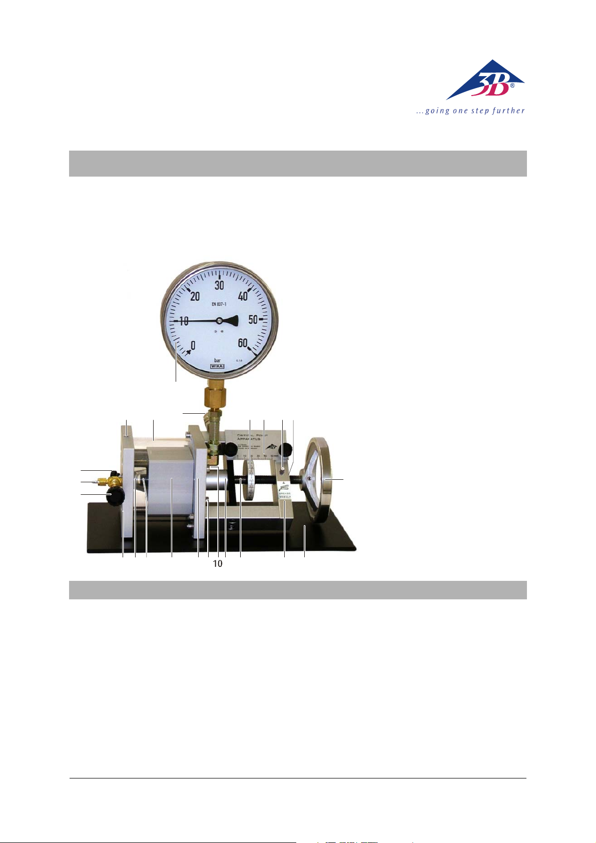
1 Vernier scale
2 Fixed scale
3 Grease nipple
4 Threaded bush
5 Handwheel
6 Base
7 Frame
8 Threaded axle with piston
9 Piston cover
10 Outlet for thermal medium
11 Inlet for thermal medium
12 End plate
13 Cylinder
14 Conical seal
1220 21
3 4
15 Measuring cell
16 Valve plate
17 Regulating valve
18 Gas connection fittings 1/8"
(for Minican® gas container)
19 Flush valve
20 Hole for thermocouple
5
21 Heat casing
22 Safety valve
23 Manometer (excess pressure indicator)
876
On delivery, the critical point apparatus is filled with
hydraulic fluid. The test gas is not included.
Before filling with the test gas, carry out a volume
calibration, as described in chapter 6, using air as an
approximation of an ideal gas.
Filling with the test gas is described in chapter 7.
Experimental investigations are described in chap-
ter 8.
Important notes on storage of the test gas and
equipment (if not in use for a long period) are stated
in chapter 9.
1516 14
1213
911
1. Contents of instruction manual
Owing to the inevitable diffusion of the test gas
through the conical seal, it is necessary to degas the
hydraulic fluid in the equipment, as described in
chapter 10. This must be done before the equipment
is put away for storage (after removing the test gas) or
if it has been in use for a long time.
The threaded bush in the frame must be lubricated
regularly and also inspected at lengthier intervals.
Refer to section 11 for instructions.
Maintenance work as described in chapter 12 is only
required if the rubber components get worn out and
their functionality is adversely affected.
1
Page 2

2. Safety instructions
When used properly, the operation of the critical
point apparatus is not dangerous, since both the
experimenter and the equipment are protected by a
safety valve. However, it is extremely important to
observe a few precautionary measures:
• Read the instruction sheet thoroughly and follow
the instructions therein.
• Do not exceed the maximum permissible values
for pressure and temperature (60 bar and 1060°C).
• Do not operate the equipment without qualified
supervision.
• Always wear safety goggles.
Only increase the temperature at low pressure with
pure gas phase in the measuring cell.
• Before increasing the temperature, wind the
handwheel outwards so that maximum volume is
attained in the measuring cell.
When conducting adjustments, make sure that the
safety valve does not point in the direction of people
who could be injured or objects that could be damaged if the valve cover shoots out. When conducting
experiments, pay special attention too to the alignment of the safety valve.
• When setting up the apparatus, make sure that
the safety valve does not point in the direction of
people who could be injured or objects that could
be damaged.
• When adjusting the safety valve, wrap your arms
around the apparatus to reach the valve at the
back.
If the conical seal is overtaxed, it could get damaged
or even destroyed.
• Never set a pressure above 5 bar if the regulating
valve or the flush valve is open, i.e. if there is no
back pressure from the gas in the measuring cell.
• Never create underpressure by turning the hand
wheel inwards when the valves are shut.
In the frame there is a threaded bush, which is to be
regarded as a safety-related feature (see section 9).
• Lubricate the threaded bush every 100 cycles.
• Inspect the threaded bush annually.
To prevent damage by corrosion inside the instrument,
• use a 2:1 mixture of water and anti-freeze fluid as
the thermal medium.
Only as real gas for SF
and nitrogen as ideal gas.
6
3. Description
The critical point apparatus allows us to investigate
the compressibility and liquefaction of a gas. Measurements allow determination of the critical point for
the gas as well as the recording of isotherms for an
adiabatic p-V diagram (Clapeyron diagram). The gas
used for testing is sulphur hexafluoride (SF
). SF6 has a
6
critical temperature of 318.6°K (45.5°C) and a critical
pressure of 3.76 MPa (37.6 bar) which makes for a
simple experiment set-up.
The critical point apparatus consists of a transparent
measuring cell of particularly well sealed, pressureresistant design. The volume of the measuring cell
can be modified by turning a fine-adjustment wheel
and can be read by means of a fixed scale and a rotating vernier scale to an accuracy of one thousandth of
the maximum volume. The pressure is applied via a
hydraulic system using castor oil approved for medicinal use. The measuring cell and hydraulic system
are isolated from one another by a conical seal which
rolls up when there is an increase in pressure. This
design means that any pressure difference between
the measuring cell and the oil reservoir is negligible
in practical terms. A manometer measures not the
pressure of the actual gas but that of the oil, thus
eliminating any need for a space within the measuring cell. When observing transitions from gas to liquid
or vice versa, the lack of such a dead space means
that the development of the very first drop of liquid
as well as the disappearance of the last bubble of gas
can be observed. The measuring cell is surrounded by
a transparent chamber of water. A circulating thermostat arrangement (water bath) means that a constant
temperature can be maintained during the experiment with a high degree of accuracy. The temperature can be read and monitored using a thermometer.
The fact that volume, pressure and temperature can
all be read with a high degree of accuracy means that
accurate p-V diagrams or pV-p diagrams can be recorded without much difficulty. Pressure and temperature-dependent volume correction enable us to
achieve accurate quantitative results which are well in
agreement with published values.
4. Contents
1 Critical point apparatus, filled with hydraulic fluid
(castor oil). With attached gas connection fittings
for MINICAN® gas container and protection for gas
supply connections. Test gas (SF
) not included.
6
1 Oil filling device
1 Allen key, 1.3 mm (for grub screw on the vernier
scale)
1 Plastic tubing, 3 mm diameter
1 1/8" tube fitting (wrench width 11 mm)
1 Grease gun
2
Page 3
J
Δ⋅=
Δ
5. Technical data
Sulphur hexafluoride:
Critical temperature: 318.6 K (45.5°C)
Critical pressure: 3.76 MPa (37.6 bar)
Critical volume: 197.4 cm
3
/mol
Critical density: 0.74 g/mol
Maximum values:
Temperature range: 10-60°C
Maximum pressure: 6.0 MPa (60 bar)
Threshold value for
safety valve: 6.3 MPa (63 bar)
Theoretical long-term
pressure: 7.0 MPa (70 bar)
Theoretical rupture
pressure: >20.0 MPa (200 bar)
Materials:
Test gas: Sulphur hexafluoride (SF
)
6
Hydraulic fluid: Castor oil
Measuring cell: Transparent acrylic
Temperature coating: Transparent acrylic
Recommended
thermal medium: mixture of water and anti freeze in the ratio 2:1
Determination of volume:
Piston diameter: 20.0 mm
Piston surface: 3.14 cm
Displaced volume: 3.14 cm
Maximum volume: 15.7 cm
2
2
× displacement
3
Scale division for
displacement: 0.05 mm
Maximum displacement: 50 mm
Determination of pressure:
Manometer: Class 1.0 (max. 1% deviation
from full scale value)
Measured quantity: Excess pressure
Indicator: 60 bar max.
Manometer diameter: 160 mm
Connections:
Hole for
temperature sensor: 6 mm dia.
Connections for
thermal medium: 7 mm dia.
Connection for
regulating valve: 1/8’’ dia.
Gas connection: 1/8’’ (3.17 mm) dia. (as
supplied)
General specifications:
Dimensions: 380 x 200 x 400 mm
3
Weight: 7 kg approx.
6. Volume calibration
6.1 Preliminary notes:
NOP M
Q
L
K
R
S
A
B C E F
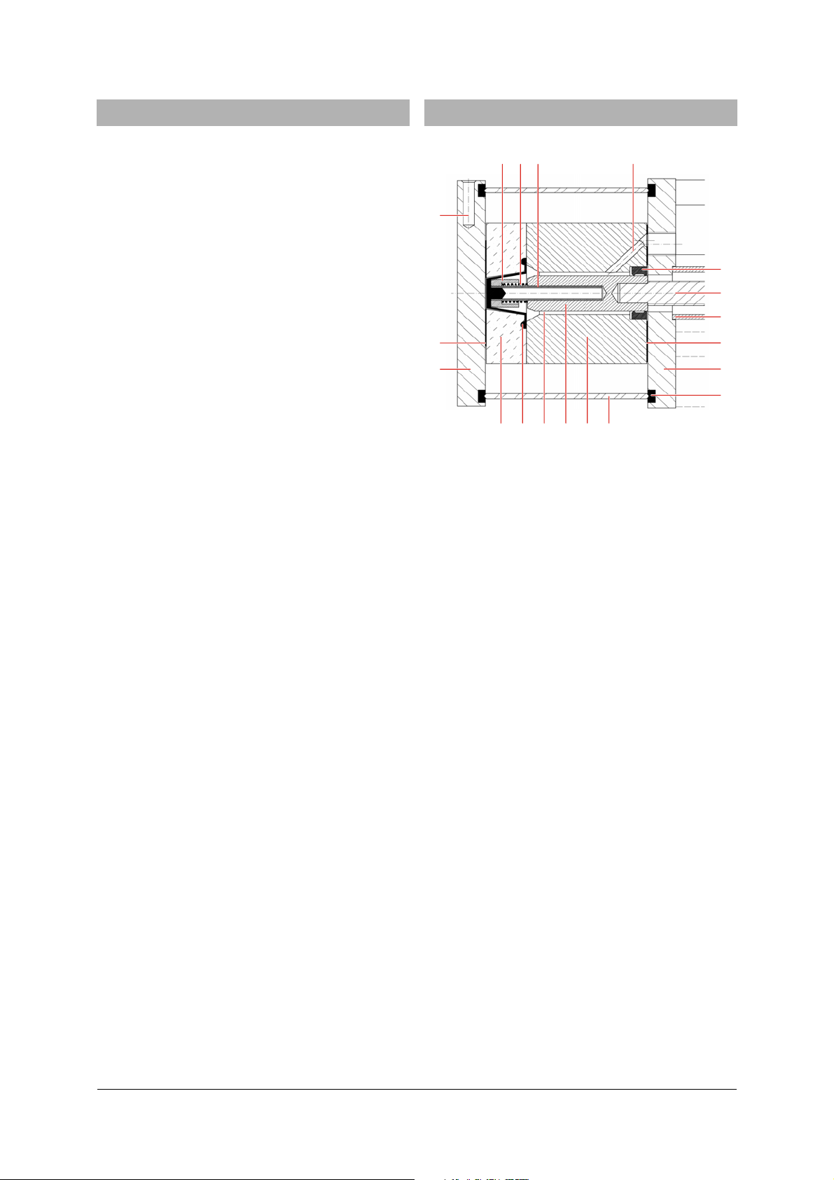
Fig. 1: Cross-section of apparatus with measuring cell (A),
conical seal (B), oil chamber (C), piston (D), cylinder (E), heat casing (F), silicone seal (G), end
plate (H), square grommet (I), piston cover (J),
threaded axle (K), gasket (L), manometer connection (M), guide tube (N), spring (O), sleeve (P), hole
for temperature sensor (Q), circular grommet (R) and
valve plate (S)
D
I
H
G
One turn of the handwheel winds the piston into/out
of the cylinder by means of a threaded axle. This
leads to a change of volume in the oil chamber (see
Fig. 1). Since oil is practically incompressible and all
the other components other than the conical seal are
almost rigid, a change in volume in the oil chamber
causes the conical seal to deform, thereby creating an
almost equal change in volume ΔV
cell. As a first approximation for ΔV
sAV
G
where
(1)
2
cm143.A= and Δs = displacement of piston.
in the measuring
G
, we can assume:
G
The piston displacement is shown in divisions of
2 mm on the fixed scale. Intermediate values are read
on the vernier scale in divisions of 0.05 mm.
The fixed scale can be moved by loosening the two
knurled screws. The vernier scale can be repositioned
and turned around the threaded axle on loosening
the grub screw (between scale positions 0 9 and 1 0).
6.2 Zero point calibration:
The zero point for the volume scale must be determined by conducting a calibration.
For this, we take advantage of the fact that in a pressure range of 1-50 bar and in a temperature range of
270-340 K, air acts as a near-ideal gas (the real gas
factor has a deviation of less than 1% from 1). Therefore, at a constant temperature (e.g. room temperature) for two piston displacements s
and s1 and for
0
3
Page 4
the corresponding pressures p0 and p1 of the trapped
T
⋅
⋅
=
air, we get:
spsp ⋅=⋅ (2)
1100
Substituting
p
s Δ⋅
1
0
=
pp
−
s
01
sss Δ+=
10
and rearranging gives:
(3)
Rough calibration of scales:
• Open the regulating valve wide.
• Loosen the grub screw for the vernier scale by
half a turn (it is now possible to turn the scale
easily on the threaded axle without moving the
handwheel, although a counterpressure acts
against this independent movement).
• Wind the handwheel out till you detect a notice-
able resistance.
• Without turning the handwheel, turn the vernier
scale on the threaded axle till the 0.0 mark is on
the top and the fixed scale shows approx. 48 mm.
• Loosen the knurled screws of the fixed scale and
shift the scale to the side till the 48-mm bar is exactly above the centre line of the vernier scale
(see Fig. 2).
• Tighten the knurled screws again. In doing so,
make sure that the fixed scale does not press
against the vernier scale.
100 20304050mm
00
19
18
17
• Calculate the zero corrected piston position s
1, corr
using Equation 3.
• Adjust the vernier scale to the corrected value
and, if necessary, move the scale again.
• If required, wind the handwheel out a little and
secure the vernier scale with the grub screw.
Measurement example:
= 1 bar, p1 = 16 bar, p1 – p0 = 15 bar
p
0
s
= 48.0 mm, s1 = 3.5 mm, Δs = 44.5 mm
0
Therefore,
s
= 2.97 mm.
1, corr
The vernier scale must therefore be adjusted so that
now only 2.97 mm are shown instead of 3.50 mm.
Note:
After calibrating the zero point, it is possible to obtain
qualitatively accurate measured values. With regard
to temperature
T and pressure p, it is also possible to
obtain quantitatively accurate measurements of the
isotherms in range around to the critical point where
the two phases exist simultaneously. However, especially in the liquid phase, the measured isotherms are
rather too widely separated.
6.3 Detailed calibration:
The exact relation between the volume VG in the
measuring cell and the scale reading
s is dependent
on the volume of oil in the oil chamber. The oil
chamber also expands marginally in proportion to the
pressure as a result of the spring in the manometer
tube. Additionally, when the temperature is increased, the castor oil expands to a greater extent
than the rest of the equipment. This means that the
pressure rises at a slightly greater rate at higher temperatures. All of these phenomena can be calculated
if appropriate calibration has been effected using air
as an ideal gas.
The ideal gas equation would thus be:
Vp
Rn
(4)
⋅=
16
with
J
3148.R =
molK
Fig. 2: Piston position reading at 48.0 mm
Zero correction:
• Shut the regulating valve (the pressure in the
measuring cell now corresponds to the ambient
pressure
p
= 1 bar. To within the accuracy of the
0
measurement, the manometer should display an
excess pressure of 0 bar).
• Wind the handwheel in till an excess pressure of
15 bar has been reached (absolute pressure
p
= 16 bar).
1
• Read the piston position s
displacement
Δs = s
– s1.
0
and calculate the
1
After taking the overpressure reading
pressure can be calculated from:
p = p
+ 1 bar (6)
e
The absolute temperature is given by:
T = ϑ + ϑ
where ϑ0 = 273.15°C (7)
0
The volume is given by:
sAV
G
where
(8)
2
cm143,A= and s is the “effective” piston
displacement.
From the measured displacement
p
, the absolute
e
s
, it is possible to
e
calculate the effective piston displacement as follows:
4
Page 5

(9)
(
)
ϑ⋅−⋅++=
CpCsss
ϑ
pe 0
By substituting in equation 4, we get:
⋅ϑ⋅β−⋅β++⋅
0
pe
ϑ+ϑ
0
Apssp
ϑ
(10)
0
=⋅−
Rn
If we take several readings at various temperatures
and pressures, we can calculate the term:
n
()
⎛
⎜
Q
=
∑
⎜
=
1i
⎝
p
ϑ+ϑ
0
Apssp
⋅ϑ⋅β−⋅β++⋅
ϑ
ii0ii
2
⎞
⎟
Rn
(11)
⋅−
⎟
⎠
Sample measurements:
Table 1: Measured values for calibration
i s
/ mm
e
ϑ
p / bar
1 40.0 20.0°C 6.6
2 20.0 20.0°C 12.4
3 10.0 20.0°C 23.3
4 5.0 20.0°C 41.8
5 3.5 20.0°C 53.9
The free parameters s
, βP, βϑ and n should be appro-
0
priately selected so that the value of Q is reduced to a
minimum.
Additionally required (see also chapter 8):
1 Compressor or bicycle pump and valve
1 Bath/circulating thermostat 1008653/1008654
1 Dig. quick-response pocket thermometer 1002803
1 Type K NiCr-Ni immersion sensor, -65°C-550°C
1002804
2 Silicone tubes, 1 m 1002622
1 l Anti-freeze fluid with corrosion-inhibiting additive
for aluminium engines (e.g., Glysantin® G30 ma-
nufactured by BASF)
Conducting the calibration:
• Connect the circulation thermostat as described
in chapter 8 and fill it with the water/anti-freeze
mixture.
• Connect the plastic tube (3-mm internal diameter)
to the 1/8" gas connection fittings.
• Open the regulating valve.
• Wind the handwheel outwards, making the piston
move till it reaches say the 46.0 mm position.
• Use a compressor or a bicycle pump to create an
excess air pressure of approx. 3-8 bar in the
measuring cell.
• Shut the regulating valve.
• To record measurements, vary the volume in the
measuring cell or the temperature of the thermostat and wait till a stationary equilibrium has
been attained. Then take a pressure reading.
• Use appropriate adjustment software to set the s
β
, βϑ and n parameters so that the quadratic
P
,
0
equation for the errors Q is reduced to a minimum (see equation 11).
• If you like, you can adjust the vernier scale
around s
so that this correction is not necessary.
0
With the set parameters, it is possible to calculate the
“effective” piston displacement s from the measured
displacement s
using Equation 9 and then to calcu-
e
late the calibrated measuring cell volume using Equation 8.
6 5.0 20.0°C 41.8
7 5.0 10.0°C 38.9
8 5.0 30.0°C 45.3
9 5.0 40.0°C 49.0
10 5.0 50.0°C 53.5
The following parameter values are obtained:
s
= 0.19 mm,
0
P
mm
0230
.=β
bar
n = 0.00288 mol.
7. Filling with test gas
7.1 Handling of sulphur hexafluoride:
Sulphur hexafluoride (SF6) is a non-toxic gas and is
absolutely safe for humans. The MAC value for danger
of suffocation on account of oxygen deprivation is
1000 ppm. That is equivalent to 6 filled measuring
cells per 1 m
However, SF
3
of air.
is extremely harmful to the environment
6
and can give rise to a greenhouse effect 24,000 times
stronger than CO
. Therefore, do not allow large quan-
2
tities to be released into the environment.
7.2 Gas connection via fixed pipes:
Additionally required:
1 SF
gas cylinder with manufacturer’s/supplier’s rec-
6
ommended gas fittings/valves, e.g. SH ILB gas cylinder
and Y11 L215DLB180 regulating valve from Airgas
(www.airgas.com).
1 Pipes with outer diameter of 1/8" and, if necessary,
adapters, e.g. from Swagelok (www.swagelok.com).
1 open-end spanner (13 mm), 1 open-end spanner
(11 mm)
According to the principles of “good laboratory practice”, it is recommended to utilise a gas supply via
fixed pipes, especially if the equipment is regularly in
operation.
Filling begins with several flush cycles in which the air
is flushed out of the pipe. The number of cycles required to flush out the air depends on the length of
mm
,
0340.=β
ϑ
grd
and
5
Page 6

the pipe (more precisely, on the ratio of the pipe
m
m
length to the volume of the measuring cell). In the
process, care should be taken that the quantity of the
greenhouse gas SF
released in the environment is
6
reduced to a minimum.
Connecting a fixed pipe:
100 20304050m
00
19
18
17
16
15
ab
Fig. 3: Connecting a fixed pipe
(a) flush valve, (b) regulating valve
• If necessary, pull out the protection for the gas
connection and loosen the valve nut (11 mm) to
remove the 1/8" gas connection fittings.
• Connect the pipe (if necessary with adapters) to
the gas fitting.
• Beginning with the valve nut, slide the supplied
screw joints onto the tubing. (See Fig. 3: follow
the sequence and alignment specified along with
the cable binder)
• Insert the pipe into the regulating valve and
tighten the valve nut till the point is reached
where it is no longer possible to move the pipe
any further using only your fingers.
• Hold the regulating valve still with an open-end
spanner (13 mm) and tighten the valve nut by a
further 270°.
Now, the connection is gas-tight. When loosening the
valve nut afterwards, the regulating valve also needs
to be held still with a spanner.
Flushing out air:
• Use the handwheel to set the piston position to
10 mm.
• Slowly open the regulating valve and let in the SF
6
till a pressure of approx. 10 bar has been attained.
• Shut the regulating valve.
• Open the flush valve slightly till the pressure has
dropped to almost 0 bar.
• Shut the flush valve.
Filling with test gas:
• After at least four flush cycles, open the regulat-
ing valve till the pressure attained is once again
10 bar.
• Shut the regulating valve.
• Turn the handwheel in the reverse direction till
the piston reaches a position of say 46 mm.
• Slowly open the regulating valve and shut it again
when a pressure of 10 bar has been attained.
7.3 Filling with gas from a MINICAN®:
Additionally required:
1 MINICAN® gas container with SF
, e.g. from the
6
company Westfalen (www.westfalen-ag.de
If the equipment is used only occasionally, it is more
practical to draw the test gas from a MINICAN® gas
container. The gas connection of a MINICAN® container is similar in design to a commercial spray can,
i.e. it opens when the MINICAN® container is pressed
directly onto the gas connection fittings.
Here too, filling begins with several rinsing cycles for
flushing out the air.
SF
6
ab
Fig. 4: Filling with test gas from a MINICAN® gas container
(a) flush valve, (b) regulating valve
Flushing out air:
• If necessary, pull off the protection for the gas
connection.
• Use the handwheel to set the piston position to
10 mm.
• After removing the protective cap, position the
MINICAN® container with SF
tion fittings.
onto the gas connec-
6
• Press the MINICAN® container onto the gas con-
nection fittings, slowly open regulating valve (b)
and let in SF
till a pressure of approx. 10 bar has
6
been attained.
• Shut the regulating valve.
10020304050m
00
19
18
17
16
15
6
Page 7

• Open the flush valve slightly till the pressure has
dropped to almost 0 bar.
• Shut the flush valve.
Filling with test gas:
• After at least four flush cycles, press the MINI-
CAN® gas container against the gas connection fittings. Slowly open the regulating valve and let in
till a pressure of approx. 10 bar has been at-
SF
6
tained.
• Shut the regulating valve.
• Wind the handwheel in the opposite direction till
the piston reaches a position of say 46 mm.
• Press the MINICAN® gas container against the gas
connection fittings, slowly open the regulating
valve and shut it again when a pressure of 10 bar
has been attained.
7.4 Recommendation for storage lasting for short
periods of time:
One gas filling can remain in the measuring cell for
several days.
If no experiments are being conducted, wind the
handwheel back till the piston is in a position where
it is subjected to the lowest possible pressure – say,
for instance, 46 mm.
If possible the apparatus should always be kept filled
with the thermal medium.
8. Experiments
8.1 Experiment set-up:
Additionally required:
1 Bath/circulating thermostat 1008653/1008654
1 Dig. quick-response pocket thermometer 1002803
1 Type K NiCr-Ni immersion sensor, -65°C-550°C
1002804
2 Silicone tubes, 1 m 1002622
1 l Anti-freeze fluid with corrosion-inhibiting additive
for aluminium engines (e.g., Glysantin® G30 ma-
nufactured by BASF)
• Place the equipment at a suitable height so that it
is convenient to observe the measuring cell. Position it so that the safety valve does not point in
the direction of any people who could be injured
or objects that could be damaged.
• Connect the silicone tubing from the outlet of the
circulation thermostat to the inlet of the heat casing and from the outlet of the heat casing to the
inlet of the circulation thermostat.
• Prepare the thermal medium consisting of 2 parts
water to 1 part anti-freeze by volume.
• Fill the circulated thermostat bath.
8.2 Qualitative observations:
Liquid and gaseous states, dynamic state during phase
transformation, transition points occurring at different temperatures.
• Vary the volume by turning the handwheel and
the temperature by means of the thermostat. Observe the safety instructions while doing so.
• Carefully shake the set-up to conduct simple
observations on the boundary between liquid and
gas.
In the vicinity of the critical point, it is also possible to
observe the critical opalescence. Owing to the constant changing of state between liquid and gaseous
states in small regions of the measuring cell, a kind of
“mist” develops and the sulphur hexafluoride appears
to be turbid.
8.3 Measuring isotherms in a p-V diagram:
• At maximum volume, set the desired temperature
on the circulation thermostat.
• Gradually reduce the volume in the measuring
cell (in steps down to a position of 10 mm). Wait
till a stationary equilibrium has been attained before taking pressure readings.
• Then, beginning with the minimum volume,
gradually increase the volume till the piston position is once again at 10 mm. Wait till a stationary
equilibrium has been attained before taking pressure readings.
• Convert the excess pressure readings into abso-
lute pressure and the piston positions into volume, as described in chapter 6.
In the low-volume region, stationary equilibrium is
attained more quickly during transition from higher
to lower pressure – i.e. from a lower volume to a
greater volume – since the phase boundary layer for
the phase transition from liquid to gas is created by
vapour bubbles present throughout the liquid. Stationary equilibrium then takes around 1 to 5 minutes
to attain, whereby the measurements on the fringe of
the region where both phases exist take longest.
The recommended threshold value of 10 mm refers to
a filling pressure of 10 bar. Above this value, there
will certainly be no occurrence of a liquid phase in
the permissible temperature range. The threshold
value shifts to the “right” if the filling pressure is
higher.
8.4 Measuring isochores in a p-T diagram:
• Set the desired initial temperature. Subsequently
set the desired volume.
• Gradually allow the temperature to decrease.
• Wait till a stationary equilibrium has been at-
tained then take the pressure reading.
Measurements where both phases are present can be
plotted to generate a vapour-pressure curve.
Attainment of equilibrium takes up to 20 minutes
after each change of temperature due to the fact that
7
Page 8

the water bath and the measuring cell must attain the
desired temperature first.
8.5 Determining the mass of gas:
Blow the gas out of the measuring cell into a gas-tight
plastic bag and then weigh it:
• If necessary, remove the gas supply pipe and
attach gas connection fittings.
• Wind out the handwheel, say to 46 mm.
• Open the regulating valve a little and release the
gas through the gas connection fittings into the
plastic bag.
• Shut the regulating valve.
• Determine the mass of the released gas. In doing
this, take into consideration the empty weight of
the bag and the buoyancy of air.
• Reduce the volume of the measuring cell till the
pressure in the measuring cell has reached its
original value.
• Calculate the original mass of gas from the vol-
ume difference before and after emptying the
measuring cell and the volume which is still present in the measuring cell.
Comparison with quoted values:
Using tabulated values, e.g. Clegg et al. [4], it is alternatively possible to calculate the mass of gas in the
measuring cell from the measurements of ϑ, p, and V.
8.6 Evaluation:
We can clearly see from Fig. 5 that, despite the relatively simple equipment, it is possible to achieve
measurements which match closely to the reference
values plotted on the graph.
8.7 Bibliography:
[1, 2] Sulphur Hexafluoride, in-house publication,
pp. 27 [1], 30 [2], Solvay Fluor und Derivate GmbH,
Hannover, Germany, 2000
[3] Otto and Thomas: Landolt-Börnstein – Numerical
Data and Functional Relationships in Science and
Technology, Vol. II, Section 1, Springer-Verlag, Berlin,
1971
[4] Clegg et al.: Landolt-Börnstein – Numerical Data
and Functional Relationships in Science and Technology, Vol. II, Section 1, Springer-Verlag, Berlin, 1971.
[5] Din, F.: Thermodynamic Functions of Gases, Vol. 2,
Butterworths Scientific Publications, London, 1956
[6] Vargaftik, N.B.: Handbook of Physical Properties of
Liquids and Gases, 2
nd
ed., Hemisphere Publishing
Corporation, Washington, 1983
[7] Nelder, J. and Mead, R.: Comp. J., Vol. 7, p. 308,
1965
9. Storage for long periods without use
If no experiments are to be conducted over a long
period, the test gas should be released and the piston
should be turned to its rest position where the conical
seal is only very slightly curled and does not press
against the walls of the measuring cell.
• If necessary, allow the equipment to cool. Wind
the handwheel back till the lowest possible pressure is present.
• Release the test gas through the flush valve.
• Turn the handwheel to move the piston to its
“rest position”, at approx. 5 mm.
• Shut the flush valve again.
• Before storing away the equipment, the hydraulic
fluid needs to be degassed (as described in chapter 10) if the equipment has been in use over a
long period of time.
• Store the equipment in a safe place where it is
not exposed to direct sunlight.
• The thermal medium should be kept in the appa-
ratus during storage, as the additives inhibit corrosion and efflorescence caused by electrochemical potentials between the different materials. Alternatively, the apparatus can be flushed with deionised water and then dried using compressed
air (oil-free, max. 1.1 bar).
8
Page 9

1
p
/ MPa
5
4
3
2
1
0
0
Fig. 5: p-V diagram of SF6, measured with the critical point apparatus:
Readings taken at 10°C (
(
Reference values from [2] for pressure of liquid at 10°C (
and 50°C (
246 81012
V
/ ml g
), 20°C ( ), 30°C ( ), 40°C ( ), 45°C ( ) and 50°C ( ),
) threshold value of liquid-gas mixture, ( ) Reference values from [1] for vapour pressure,
), 20°C ( ), 30°C ( ), 40°C ( )
)
9
-
Page 10

10. Degassing the hydraulic fluid
Owing to the inevitable diffusion of the test gas
through the conical seal, the pressure in the measuring cell slowly decreases over a long period. The gas
diffusing through the conical seal first dissolves in the
hydraulic fluid but does not have any significant influence on the measurements.
However, if the test gas is removed from the equipment (for storage of the equipment) and the pressure
of the hydraulic fluid consequently falls to the ambient pressure, then the test gas will escape from the
hydraulic fluid due to Henry's law. This leads to a
gradual increase in pressure in the oil chamber which
must be avoided at all costs as there is no back pressure in the measuring cell. On account of this, it is
necessary to cleanse the hydraulic fluid of all gas
before storing the equipment.
To degas the hydraulic fluid, the oil is made to boil in
a vacuum. Since the pressure difference on both sides
of the conical seal should not exceed a particular
limit, it is necessary to maintain, as best as possible,
the existing underpressure constant on the gas side.
Additionally required:
1 Castor oil approved for medicinal use e.g. 1002671
1 Vacuum tube, 6 mm internal diameter
1 Stopcock (or variable-leak valve)
1 Vane-type rotary pump
1 Open-end spanner (14 mm), 1 pair of tweezers
Absorbent paper, cardboard box
Storage of the equipment:
• If necessary, allow the equipment to cool. Wind
the handwheel back till the lowest possible is present.
• Release the test gas through the flush valve and
shut the flush valve thereafter.
• If necessary, remove the gas supply pipe and
attach the gas connection fittings.
• Unscrew the vernier scale.
• Open the regulating valve.
• Wind the handwheel so that piston moves in till
an excess pressure of 1 bar has been attained.
• Shut the regulating valve.
• Wind the handwheel back by two turns.
• Place the equipment with the manometer facing
downwards towards the ground). The manometer
should rest on a support approx. 6-cm-thick (see
Fig. 6).
Caution: the piston should never be wound out to
more than 25 mm, since the guide tube may slip out
during subsequent operations.
Fig. 6: Storage of the equipment for oil filling
c, d
e
d
c
Fig. 7: Dismantling the safety valve
(c) counter nut, (d) valve cap, (e) compression spring,
(f) hexagonal piston, (g) steel ball bearing
f
g
Dismantling the safety valve:
• Loosen the counter nut (14 mm) and use a screw-
driver to remove the valve cap (see Fig. 7).
• Remove the compression spring, the hexagonal
piston and the steel ball bearing in succession
with a pair of tweezers and store them in a safe
place, for instance in a cardboard box.
Assembly of the oil filling device:
• Loosen the valve nut of the oil filling device, re-
move the cover and place the valve nut above the
safety valve (see Fig. 8).
• Do not screw the oil filling device on too tight (the
gasket ring should not be squeezed out).
• Open the regulating valve.
• Wind the handwheel inwards to its end position
up to the frame (if necessary, loosen the vernier
scale). Subsequently wind the handwheel out by 3
turns.
• Place absorbent paper underneath and fill the oil
container with castor oil to no more than half
way.
• Screw on the cover of the oil filling device with
the valve nut.
Connection of vacuum pump:
• Connect a plastic hose with 3 mm internal diame-
ter to the gas connection fittings of the equipment and the smaller connector of the oil filling
device.
10
Page 11

k
l
• In order to connect the vacuum pump, take a
vacuum hose with 6 mm internal diameter and
connect it via a stopcock or preferably via a threeway valve to the larger connector of the oil filling
device.
i
h
Fig. 8: Assembly of the oil filling device and connection of
vacuum pump (h) oil container, (i) valve nut,
(k) cover, (l) stopcock (or variable-leak valve)
Degassing:
• Check whether the regulating valve is open and
the flush valve is shut.
• Switch on the vacuum pump. Open the stopcock a
little and observe the formation of bubbles in the
castor oil.
Close the stopcock to interrupt the evacuation process
if the formation of bubbles is so strong that they can
reach the filter that is mounted on the cover. The
stopcock may be opened only after the bubbling has
subsided.
After several minutes (depending on the suction capacity of the connected vacuum pump), the vaporising pressure of the castor oil is attained and the oil
begins to boil. This can be noticed when vapour bubbles begin to form “out of the blue” and rapidly become larger in size as they move through the oil.
The oil is now is sufficiently degassed.
• Shut the regulating valve and the stopcock.
Dismantling:
• Pull out the vacuum hose from the stopcock (the
hose fitting with the stopcock continues to remain on the oil filling device).
• To avoid any surges, slowly open the stopcock
and wait for the pressure to even out.
• Pull out the hoses from both of the connectors on
the oil filling device.
• Unscrew the container from the safety valve.
Since castor oil is relatively viscous, it trickles out of
the container very slowly. Thus, this step can be conducted easily. A cleaning cloth (or kitchen paper)
which is held below the container immediately after
unscrewing it prevents any drops forming.
• With a cleaning cloth, remove excess oil from the
safety valve and subsequently wind the handwheel inwards very slightly till the oil level in the
valve is exactly at the same level as the edge
where the steel ball bearing sits.
• Insert the steel ball bearing, position the hexago-
nal piston with the short bore onto the ball bearing (use tweezers for this) and insert the compression spring into the longer bore.
• Carefully screw the valve cap on in its end posi-
tion (not too tight) and loosen it by two turns.
Positioning the safety valve:
• Set-up the equipment and place it in a way that
the safety valve does not point in the direction of
people who could get injured or objects which
could get damaged.
• Open the regulating valve. Wind the handwheel
fully out and shut the regulating valve again.
• Turn the handwheel in till an excess pressure of
approx. 65 bar has been attained.
• From the front, wrap your arms around the appa-
ratus to reach the safety valve located at the back.
Slowly unscrew the valve cap of the safety valve
till the pressure drops to approx. 63 bar.
• Tighten the counter nut (14 mm).
Rest position:
• Wind the handwheel back till the pressure has
dropped to max. 10 bar.
• Open the regulating valve and turn the hand-
wheel to its “rest position” at approx. 5 mm.
• Shut the regulating valve.
After completing these steps, the equipment can
either be stored or refilled with test gas.
11. Upkeep and maintenance of threaded bush
11.1 Lubricating the threaded bush
To minimise wear, the threaded bush in the frame
should be lubricated approximately every 100 cycles
(one cycle = a pressure increase from 10 to 60 bar and
the subsequent reduction to 10 bar), or once weekly.
Lubrication only takes about 1 min and extends the
service life of the bush significantly. For lubrication, a
light-coloured multi-purpose grease with no graphite
or similar additives is recommended.
Procedure:
• Inject one full stroke of lubricant from a conven-
tional grease gun into the threaded bush through
the nipple at the frame.
• Wipe up any surplus lubricant emerging from the
bush.
When it emerges, the lubricant will also pick up any
traces of plastic that might have worn off during operation, so that will be flushed out too.
11
Page 12

11.2 Examine threaded bush.
The threaded bush in the frame is subject to slow but
constant wear, and therefore the axial play must be
checked once a year:
• Release the pressure from the measuring cell and
adjust the piston to the 10 mm position.
• Using a vernier caliper, determine the minimum
and maximum distance between the handwheel
flange and frame; to do so, first wind in the
handwheel and then wind it out.
If the two distances differ by more than 0.3 mm, then
the bush needs to be replaced.
11.3 Replacing the threaded bush
Additionally required:
1 Threaded bush from set of seals (1002672)
The threaded bush is to be replaced no later than
every ten years even if the limit of wear has not been
reached (tests on a rig failed to produce any measurable wear [<0.05 mm] after 1000 cycles), because
reliable data on the long-term stability of the plastic
used (POM-C) are not yet available.
• Depressurise the measuring cell.
• Unscrew the fixed scale.
• Undo the grub screw of the handwheel flange and
remove handwheel.
• Loosen the four screws in the cross piece of the
frame and remove it along with the threaded
bush by winding it down the axle.
• Unscrew the lubricating nipple (size SW 7) and use
a 3-mm Allen key to loosen the threaded pin
screwed in across the threaded bush by 4 turns.
• Knock the threaded bush out from the side of the
handwheel using a suitable mandrel. Alternatively insert an M14 screw loosely into the bush
and force the bush by hitting the head of the
screw.
• Fit the new bush such that the cross piece is
aligned with the lubrication nipple.
• Clamp the bush in a vice (with flat jaws or suit-
able insert).
• Screw back in the threaded pin (min. 6.0 mm
countersunk) and the lubricating nipple.
Bush material: POM-C = Polyoxymethylene copolymer
Oversize (press fit): 0.05 – 0.1 mm.
12. Changing the seals
Additionally required:
1 Allen key (6 mm)
1 Set of seals for critical point apparatus 1002672
consisting of
1 Conical seal,
1 Circular grommet,
1 Grommet 78x78 mm
2
,
4 Copper gasket washers
1 Threaded bush
After a certain period of time, it may be necessary to
replace the conical seal or other seals, especially if the
equipment has been exposed to direct sunlight.
12.1 Dismantling the equipment:
• If necessary, allow the equipment to cool and
wind the handwheel back till the lowest possible
pressure is present.
• Release the test gas through the flush valve and
shut the flush valve.
• If necessary, dismantle the tubing.
• Open the regulating valve.
• Wind the handwheel back till it has come to a
position of 25 mm.
• Tilt the equipment to the right and place it in an
upright position on a suitable surface resting on
the handwheel and the edge of the equipment
base.
• Use the Allen key (6 mm) to uniformly loosen
each of the four screws in the valve plate by 1/8
of a turn till the tension has been reduced.
• Unscrew and remove the screws.
• Also remove the copper gasket washers.
• With increasing force, twist the valve plate to the
left and right till the seals have been loosened.
Do not twist the regulating valve.
• Remove the valve plate (the measuring cell might
still be sticking to the plate).
• Twisting the equipment some more to loosen the
remaining seals between the measuring cell and
the cylinder and between the measuring cell and
the valve plate.
• Twist the guide tube to remove it from the coni-
cal seal.
12.2 Cleaning the dismantled equipment:
Castor oil can be removed quite easily by using white
spirit. However, white spirit attacks the acrylic of the
casing and measuring cell. Use a (mild) washing-up
liquid solution to remove greasy finger marks and
other impurities. New seals too should be cleaned
with white spirit and a washing-up liquid.
12
Page 13

12.3 Assembling the equipment:
In case castor oil had been removed from the oil
chamber:
• Pour a fresh quantity of castor oil in up to about
5 mm below the upper edge of the cylinder (at
the beginning of the depression).
• Insert both of the silicone seals.
• Turn the conical seal inside out and dampen the
stud with some castor oil then screw it into the
guide tube.
• Unfold the conical seal back to its original shape,
position the spring on the piston and insert the
guide tube into the piston.
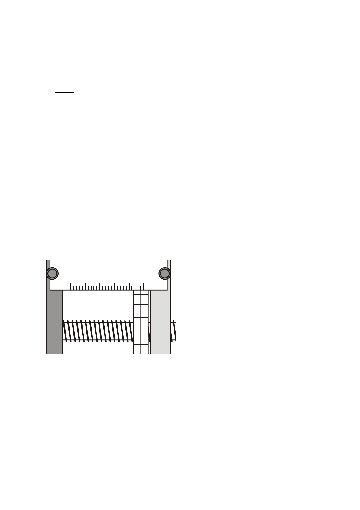
• Mount the measuring cell and position it flush
along the edges of the cylinder.
• Place the heat casing at the centre of the lower
silicone seal.
• Fit the circular grommet and, with the help of a
ruler placed on the heat casing, position it parallel to the cylinder (see Fig. 9, the semicircular
holes should then be below the valve openings).
Fig. 9: Positioning the circular grommet
• Place the valve plate at the centre and position it
parallel to the end plate.
• Fit the M8×40 screws with new copper gasket
washers and loosely screw them in.
• Tighten the screws. Take care to ensure that there
is uniform pressure on the circular grommet (if
the pressure is too high, the grommet makes a
greyish mark on the transparent acrylic, whereas
if the pressure is lower the surface looks milky).
12.4 Recommissioning:
• Degas the hydraulic fluid and pour the oil into
the equipment (see chapter 10).
• Position the safety valve (see chapter 10).
• Conduct a fresh volume calibration (see chap-
ter 6).
3B Scientific GmbH • Rudorffweg 8 • 21031 Hamburg • Germany • www.3bscientific.com
Subject to technical amendments
© Copyright 2013 3B Scientific GmbH
Page 14

 Loading...