

Page 1

www.2n.cz
2N IP Style
®
Door Entry IP Intercom
Installation Manual
Version: 1.0
Page 2

The 2N TELEKOMUNIKACE a.s. is a Czech manufacturer and supplier of
telecommunications equipment.
The product family developed by 2N TELEKOMUNIKACE a.s. includes GSM gateways,
private branch exchanges (PBX), and door and lift communicators. 2N
TELEKOMUNIKACE a.s. has been ranked among the Czech top companies for years
and represented a symbol of stability and prosperity on the telecommunications
market for almost two decades. At present, we export our products into over 120
countries worldwide and have exclusive distributors on all continents.
2N is a registered trademark of 2N TELEKOMUNIKACE a.s. Any product and/or other
®
names mentioned herein are registered trademarks and/or trademarks or brands
protected by law.
2N TELEKOMUNIKACE a.s. administers the FAQ database to help you quickly find
information and to answer your questions about 2N products and services. On www.
faq.2n.cz you can find information regarding products adjustment and instructions for
optimum use and procedures „What to do if...".
2N TELEKOMUNIKACE a.s. hereby declares that the 2N product complies with all
basic requirements and other relevant provisions of the 1999/5/EC directive. For the
full wording of the Declaration of Conformity see the CD-ROM (if enclosed) or our
website at www.2n.cz.
This device complies with part 15 of the FCC Rules. Operation is subject to the
following two conditions: (1) This device may not cause harmful interference, and (2)
this device must accept any interference received, including interference that may
cause undesired operation.
Page 3

The 2N TELEKOMUNIKACE a.s. is the holder of the ISO 9001:2009 certificate. All
development, production and distribution processes of the company are managed by
this standard and guarantee a high quality, technical level and professional aspect of
all our products.
Page 4

Content:
1. Product Overview
1.1 Components and Associated Products
1.2 Terms and Symbols
2. Description and Installation
2.1 Before You Start
2.2 Mechanical Installation
2.2.1 Chassis Installation
2.2.2 Mounting Box Installation
2.3 Electric Installation
2.3.1 Overvoltage Protection
2.4 Extending Module Connection
3. Function and Use
3.1 Configuration
3.1.1 2N® IP Style LAN Location via 2N® Network Scanner
3.2 2N® IP Style User Control
3.3 Intercom Control as Viewed by Internal User
3.4 Maintenance
3.5 Downloads
4. Technical Parameters
5. Supplementary Information
5.1 Troubleshooting
5.2 Directives, Laws and Regulations
5.3 General Instructions and Cautions
2N TELEKOMUNIKACE a.s., www.2n.cz 4/105
Page 5

1. Product Overview
Here is what you can find in this section:
1.1 Components and Associated Products
1.2 Terms and Symbols
2N TELEKOMUNIKACE a.s., www.2n.cz 5/105
Page 6

Basic Features
2 N IP Style ®– is an elegant and reliable intercom equipped with lots of useful
functions. Thanks to SIP support and compatibility with major brands of PBX
manufacturers, it can benefit from using VoIP networks. can be used as a 2N®IP Style
door or special-purpose intercom for office buildings, residential areas and other
applications.
– allows the called user to see the calling persons on the 2N Wide-angle HD camera
answering units, videophone displays or PC screens. The intercom is equipped with
night vision, which automatically selects the night/day mode according to light.
– displays the list of destinations (groups/individuals) for outgoing 10" touch display
call setups. You can set up to three phone numbers and call time profiles to each of
the buttons to make the called subscriber accessible any time.
– touch numeric keypad allowing you to use the intercom as a code lock for Keypad
lock switch activation or for making calls to a selected user phone/virtual number.
– integrated card reader providing access control management using 125 Card Reader
kHz and 13.56 MHz (optionally secured) RFID cards. With the advanced features,
functions other than the door lock can be RFID card controlled too.
– this switch can be controlled using an RFID card reader, a Electric lock switch
numeric keypad, the 2N Mobile Key application in your smartphone, a PC application
®
or during a call from any phone. If necessary, more modules with required outputs can
be added.
– is designed as a robust, mechanically resistant intercom, Robustness 2N IP Style
®
which withstands any weather conditions without the need of additional accessories.
– thanks to the integrated acoustic echo cancellation (AEC), full duplex Audio quality
communication provides bilateral audibility even when the callers are speaking at the
same time.
– the option is to use surface installation using a chassis or Installation of 2N IP Style
®
flush mounting using a wall mounting box.
– use a PC equipped with any Internet browser. Use Configuration of 2N IP Style
®
2N
®
to configure extensive installations of multiple intercoms.Access Commander
2N TELEKOMUNIKACE a.s., www.2n.cz 6/105
Page 7

Advantages of Use:
Elegant design
touch display10"
Weather resistance
Surface/flush mounting
Sensitive microphone and Speakerphone
Bidirectional communication – acoustic echo cancellation
Integrated color HD camera with a wide-angle lens and night vision
Touch numeric keypad
Integrated electric lock switches with wide setting options
Integrated 125 kHz and 13.56 MHz (optionally secured) RFID card reader
LAN (PoE+) or external 12 V / 4 A power supply
Configuration via device web interface
SIP 2.0 and SIPS support
Up to 10 000 phone book positions
Up to 20 user time profiles
Video codecs (H.264, MJPEG)
Audio codecs (G.711, G.729, G.722, L16/16 kHz)
HTTP server for configuration
SNTP client for server time synchronization
RTSP server for video streaming
SMTP client for email sending
TFTP/HTTP client for automated configuration and firmware update
2N TELEKOMUNIKACE a.s., www.2n.cz 7/105
Page 8

1.1 Components and Associated Products
Main Units
Part No. 9157101
2N IP Style
®
Main Unit
Internal 125 kHz and 13.56 MHz card reader
Part No. 9157101-S
2N IP Style
®
Main Unit
Internal 125 kHz and secured 13.56 MHz card reader
2N TELEKOMUNIKACE a.s., www.2n.cz 8/105
Page 9

Mounting Accessories
Part No. 9157002
2N IP Style® surface mounting chassis
Part No. 9157001
2N IP Style® flush mounting box
2N TELEKOMUNIKACE a.s., www.2n.cz 9/105
Page 10

Extending Modules
Part No. 9155030
2N IP
®
Verso – Infopanel
The Infopanel module helps you place such
information into the intercom installation as
house number, opening hours and similar data.
The Infopanel backlight is software controlled.
Part No. 9155032
2N IP
®
Verso – 125 kHz RFID card reader
The card reader module provides access
control via contactless cards or key fobs. The
module supports the 125 kHz EM4xxx cards.
Part No. 9155082
2N IP Verso® – 125 kHz, 13.56 MHz, NFC/HCE
Bluetooth & RFID card reader
The Bluetooth and card reader module
provides access control via contactless cards
or key fobs. The module also supports the 125
kHz and 13.56 MHz cards and other carriers:
125 kHz
EM4xxx
13.56 MHz
ISO14443A (Mifare, DESFire)
PicoPass (HID iClass)
FeliCa
ST SR(IX)
2N Mobile Key
®
2N TELEKOMUNIKACE a.s., www.2n.cz 10/105
Page 11

Extending Modules
Part No. 9155084
2N IP Verso® – 125 kHz, secured 13.56 MHz,
NFC/HCE Bluetooth & RFID card reader
The card reader module provides access
control via contactless cards or key fobs. The
module also supports the 13.56 MHz cards and
other carriers of the following standards:
125 kHz
EM4xxx
13.56 MHz
ISO14443A (Mifare, DESFire)
PicoPass (HID iClass)
FeliCa
ST SR(IX)
2N Mobile Key
®
HID SE (Seos, iClass SE, Mifare
SE)
Part No. 9137422E
2N IP - External Bluetooth reader (USB interface)
®
An external Bluetooth reader connected via
USB to your computer.
It can be used for pairing new users who want
to use their smartphones with the 2N Mobile
®
application for access to controlled areas.Key
A USB driver is required for the external reader
to work properly.
2N TELEKOMUNIKACE a.s., www.2n.cz 11/105
Page 12

Extending Modules
Part No. 9155034
2N IP
®
Verso – I/O
The module provides logical inputs and
outputs for integration of sensors or other
devices. The module is installed under another
module, i.e. needs no separate position.
Inputs and outputs
RELAY1 – RELAY1 terminals with
accessible 30 V / 1 A AC/DC NO/NC
contact
RELAY2 – RELAY2 terminals with
accessible 30 V / 1 A AC/DC NO/NC
contact
IN1 – IN1 terminals for input used in
passive/active mode ( 30 V to +30 V −
DC)
OFF = open contact or U > 1.5 V
IN
ON = closed contact or U < 1.5 V
IN
IN2 – IN2 terminals for input used in
passive/active mode ( 30 V to +30 V −
DC)
OFF = open contact or U > 1.5 V
IN
ON = closed contact or U < 1.5 V
IN
TAMPER – Input for tamper switch
connection, 9155038
Part No. 9155037
2N IP
®
Verso – Wiegand
The module helps you interconnect your
system with other systems via the Wiegand
interface. The module is installed under another
module, i.e. needs no separate position.
2N TELEKOMUNIKACE a.s., www.2n.cz 12/105
Page 13

Extending Modules
Part No. 9155038
2N IP
®
Verso – Tamper switch
The module secures your system against
tampering by detecting intercom opening or
top frame removing. The module is installed on
a special place and needs no separate position.
Remember to purchase the I/O module, Part
No. 9155034, along with the tamper switch.
Part No. 91550942
2N IP
®
Verso – 13.56 MHz NFC/HCE RFID card
reader
The card reader module provides access
control via contactless cards or key fobs. The
module also supports the 13.56 kHz cards and
other carriers of the following standards:
ISO14443A (Mifare, DESFire)
PicoPass (HID iClass)
FeliCa
ST SR(IX)
2N Mobile Key
®
Part No. 9155046
2N IP
®
Verso – Bluetooth reader
It helps you open the door using the
combination of the Bluetooth technology and a
smartphone with the 2N Mobile Key
®
application.
2N TELEKOMUNIKACE a.s., www.2n.cz 13/105
Page 14

Extending Modules
Part No. 9155045
2N IP
®
Verso – Fingerprint reader
Used for verification of human fingerprints for
access control and intercom/third party
equipment control.
Part No. 9155041
2N IP
®
Verso – Induction loop
Used for audio signal transmission directly into
a hearing aid via a magnetic field.
Part No. 9155086
2N IP
®
Verso – Secured 13.56 MHz NFC/HCE
RFID card reader
Compatible with firmware 2.13 and higher.
The card reader module provides access
control via contactless cards or key fobs. The
module supports the 13.56 MHz cards and
other carriers of the following standards:
ISO14443A (Mifare, DESFire)
PicoPass (HID iClass)
FeliCa
ST SR(IX)
2N Mobile Key
®
HID SE (Seos, iClass SE, Mifare SE)
2N TELEKOMUNIKACE a.s., www.2n.cz 14/105
Page 15

Extending Modules
Part No. 9155050
1 m interconnecting cable
Only one interconnecting cable is allowed in a
single installation.
The maximum bus length is 7 m.
Part No. 9155054
3 m interconnecting cable
Only one interconnecting cable is allowed in a
single installation.
The maximum bus length is 7 m.
Part No. 9155055
5 m interconnecting cable
Only one interconnecting cable is allowed in a
single installation.
The maximum bus length is 7 m.
2N TELEKOMUNIKACE a.s., www.2n.cz 15/105
Page 16

Indoor Units and Accessories
Part No. 91378601
2N Indoor View® – black
Indoor answering audio/video unit with a
touchscreen designed for all 2N IP intercoms
Part No. 91378601WH
2N Indoor View® – white
Indoor answering audio/video unit with a
touchscreen designed for all 2N IP intercoms
Part No. 91378501
2N Indoor Compact® – black
Indoor answering audio/video unit with a
touchscreen designed for all 2N IP intercoms
2N TELEKOMUNIKACE a.s., www.2n.cz 16/105
Page 17

Part No. 91378501WH
2N Indoor Compact® – white
Indoor answering audio/video unit with a
touchscreen designed for all 2N IP intercoms
Part No. 91378401
2N Indoor Talk® – black
Indoor answering audio unit with a touchscreen
designed for all 2N IP intercoms
Part No. 91378401WH
2N Indoor Talk® – white
Indoor answering audio unit with a touchscreen
designed for all 2N IP intercoms
2N TELEKOMUNIKACE a.s., www.2n.cz 17/105
Page 18

91378800Part No.
Wall/plasterboard flush mounting box for 2N indoor
answering units.
Part No. 91378803
Wall surface mounting box for 2N answering units.
91378802Part No.
Stand for 2N indoor answering units.
2N TELEKOMUNIKACE a.s., www.2n.cz 18/105
Page 19

Part Numbers:
91378375
91378376
2N Indoor Touch 2.0® – black
WiFi version (second Part No.)
2N Indoor Touch 2.0®, an elegant indoor touch
panel, is designed for all . The 2N IP intercoms
display panel shows you the person standing at
your door and helps you make conversation with
the visitor, open the door lock or switch on the
entrance hall lights.
Part Number:
91378382
2N Indoor Touch® – desk stand black
Part Numbers:
91378375WH
91378376WH
2N Indoor Touch 2.0® – white
WiFi version (second Part No.)
2N Indoor Touch 2.0®, an elegant indoor touch
panel, is designed for all of the . The 2N IP intercoms
display panel shows you the person standing at
your door and helps you make conversation with
the visitor, open the door lock or switch on the
entrance hall lights.
2N TELEKOMUNIKACE a.s., www.2n.cz 19/105
Page 20

Part Number:
91378382W
2N Indoor Touch® – Desk stand white
2N TELEKOMUNIKACE a.s., www.2n.cz 20/105
Page 21

VoIP Phones
91378357Part.No.
Grandstream GXV3240 VoIP video telephone
GXV3240 is a successor to the popular GXV3140 model,
which provides comfortable video calls in the IP network.
Touchscreen and keypad control.
91378358Part No.
Grandstream GXV3275 VoIP video telephone
GXV3275 is a successor to the popular GXV3175 model, which
provides comfortable video calls in the IP network.
Touchscreen control.
Part No. 1120101B
2N IP Handset ®– black
Basic answering audio unit
2N TELEKOMUNIKACE a.s., www.2n.cz 21/105
Page 22

Part No. 1120101W
2N IP Handset ®– white
Basic answering audio unit
2N TELEKOMUNIKACE a.s., www.2n.cz 22/105
Page 23

Electric Locks
932071EPart No.
BEFO 11211
12 V / 230 mA DC
low consumption
932081EPart.No.
BEFO 11221 with momentum pin
12 V / 230 mA DC
low consumption
A very short electric pulse is enough to put the lock into the
OPEN position and unlock the door. After passage, the lock
gets in the CLOSED (relax) position again.
932091EPart.No.
BEFO 11211MB with mechanical blocking
12 V / 230 mA DC
low consumption
You can set the lever mechanically into the OPEN or CLOSED
position. When OPEN, the lock is constantly open, when
CLOSED, it is a standard lock.
2N TELEKOMUNIKACE a.s., www.2n.cz 23/105
Page 24

Part No. 932061E
BEFO 211211with momentary pin, mechanical blocking
low consumption
12 V /230 mA DC
A regular lock with a built-in contact to indicate whether the
door is open/closed.
Part No. 932072E
BEFO 31211
reversible
12 V / 170 mA DC
The reversible lock is closed when electricity is switched on.
When electricity is interrupted, the lock is opened.
Part No. 932062E
BEFO 321211
reversible plus door signaling
12 V / 170 mA
The reversible lock is closed when electricity is switched on.
When electricity is interrupted, the lock is opened.
It contains a built-in contact to indicate whether the door is
open/closed.
Tip
FAQ: Electric locks - Differences between locks for 2N IP intercoms
2N TELEKOMUNIKACE a.s., www.2n.cz 24/105
Page 25

Power Supply
Part Numbers 91378101
PoE+ injector
For intercom supply via the Ethernet cable where the PoE+
switch is absent.
932928Part No.
12 V transformer
For 230 V mains voltage.
For external power supply of the lock with 12 V AC voltage.
Two-Wire Connection
Part No. 9159014EU/US
/UK
2N 2Wire
®
(set of 2 adapters plus EU/US/UK power supply)
The converter allows you to use the existing two-2N 2Wire
®
wire cabling from your original door bell or door intercom and
connect any IP device to it. You do not have to configure
anything, all you need is one unit at each end of 2N 2Wire
®
the cable and a power supply connected to them.
2N TELEKOMUNIKACE a.s., www.2n.cz 25/105
Page 26

13 MHz RFID
Part No. 9159031
External 13.56 MHz RFID card reader, Wiegand
Secondary reader for connection to an internal reader. It
provides card access control from both sides of the door.
IP68 cover, also suitable for exteriors. Card types:
ISO14443A (Mifare, DESFire)
PicoPass (HID iClass)
FeliCa
ST SR(IX)
2N Mobile Key
®
Part No. 9137421E
13.56 MHz, 125 kHz NFC/HCE USB RFID card reader
External RFID card reader connectable to a PC via a USB
interface. Suitable for system administration and adding of
13.56 MHz, 125 kHz cards and Android platform devices
supporting NFC/HCE using the web 2N IP intercom
interface or . The same card2N Access Commander
®
/device types are read as in the card 2N IP intercom
readers:
125 kHz
EM4xxx
13.56 MHz
ISO14443A (Mifare, DESFire)
PicoPass (HID iClass)
FeliCa
ST SR(IX)
2N Mobile Key
®
2N TELEKOMUNIKACE a.s., www.2n.cz 26/105
Page 27

Part No. 9137424E
Secured 13.56 MHz, 125 kHz NFC/HCE USB RFID card
reader
External secured RFID card reader connectable to a PC via
a USB interface. Suitable for system administration and
adding of 13.56 MHz, 125 kHz cards and Android platform
devices supporting NFC/HCE using web 2N IP intercom
interface or the application. The 2N Access Commander
®
same card/device types are read as in the 2N IP intercom
card readers:
125 kHz
EM4xxx
13.56 MHz
ISO14443A (Mifare, DESFire)
PicoPass (HID iClass)
FeliCa
ST SR(IX)
2N Mobile Key
®
HID SE (Seos, iClass SE, Mifare SE)
9134173Part No.
Mifare Classic 1k RFID card, 13.56 MHz
2N TELEKOMUNIKACE a.s., www.2n.cz 27/105
Page 28

Part No. 9134174 Mifare Classic 1k RFID fob, 13.56 MHz
2N TELEKOMUNIKACE a.s., www.2n.cz 28/105
Page 29

125 kHz RFID
Part No. 9159030 External 125 MHz RFID card reader, Wiegand
Secondary reader for connection to an internal reader. It
provides card access control from both sides of the door. IP68
cover, also suitable for exteriors. Reads EM4xxx cards.
Part No. 9137420E 125 kHz USB RFID card reader
External RFID card reader connectable to a PC via a USB
interface. Suitable for system administration and adding of
EM4xxx cards using .2N Access Commander
®
9134165EPart No. RFID card, type EM4100, 125 kHz
9134166EPart No. RFIDKey fob , type EM4100, 125 kHz
2N TELEKOMUNIKACE a.s., www.2n.cz 29/105
Page 30

Biometry
Part No. 9137423E
2N IP intercom®- external fingerprint reader (USB interface)
Used for scanning user fingerprints into the device system in
case an extending fingerprint reader module is connected to 2N
. IP Style
®
2N TELEKOMUNIKACE a.s., www.2n.cz 30/105
Page 31
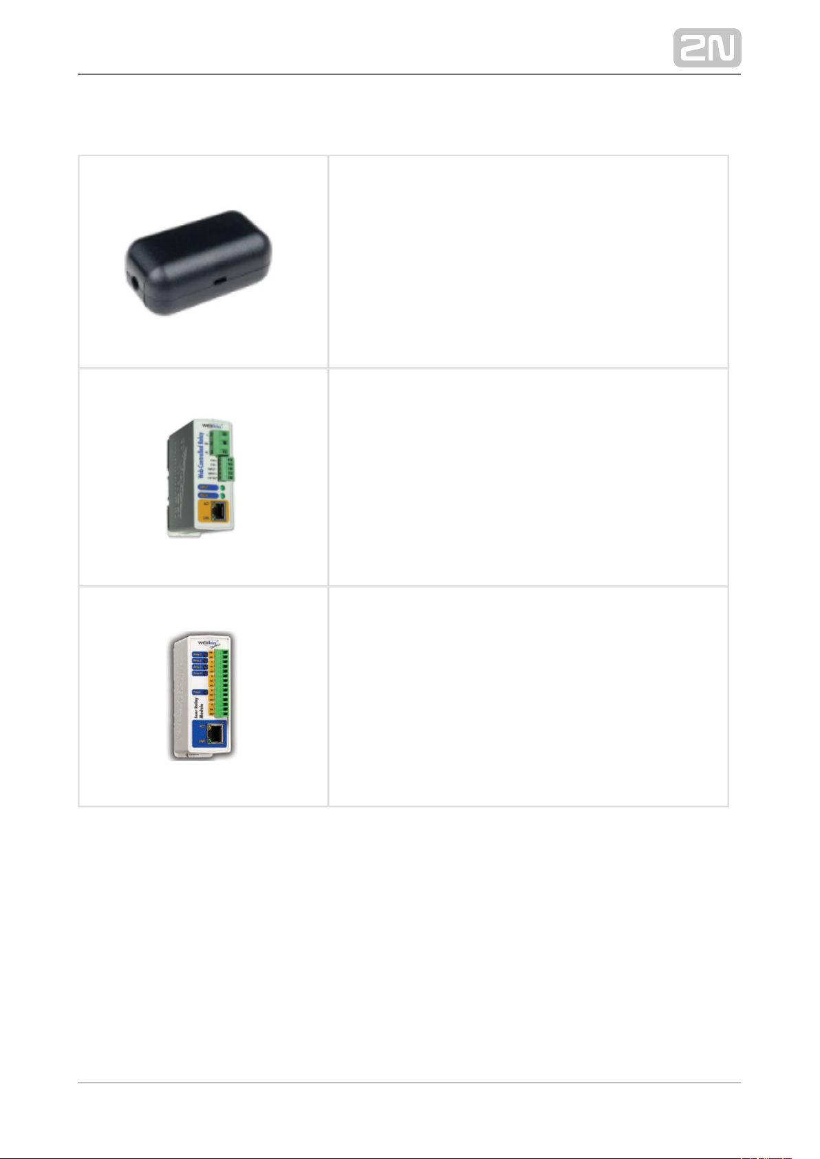
External Switches
9159010Part No.
2N® Security Relay
A handy add-on that significantly enhances security
Prevents lock tampering. Installed between the intercom,
from which it is also supplied, and the lock to be
controlled.
9137410EPart No. External IP relay – 1 output
A stand-alone IP device, which can be controlled from an
HTTP IP intercom via commands. Helps control devices
from an unlimited distance.
9137411EPart No. External IP relay – 4 outputs, PoE
A stand-alone IP device, which can be controlled from an
HTTP IP intercom via commands. Helps control devices
from an unlimited distance.
2N TELEKOMUNIKACE a.s., www.2n.cz 31/105
Page 32
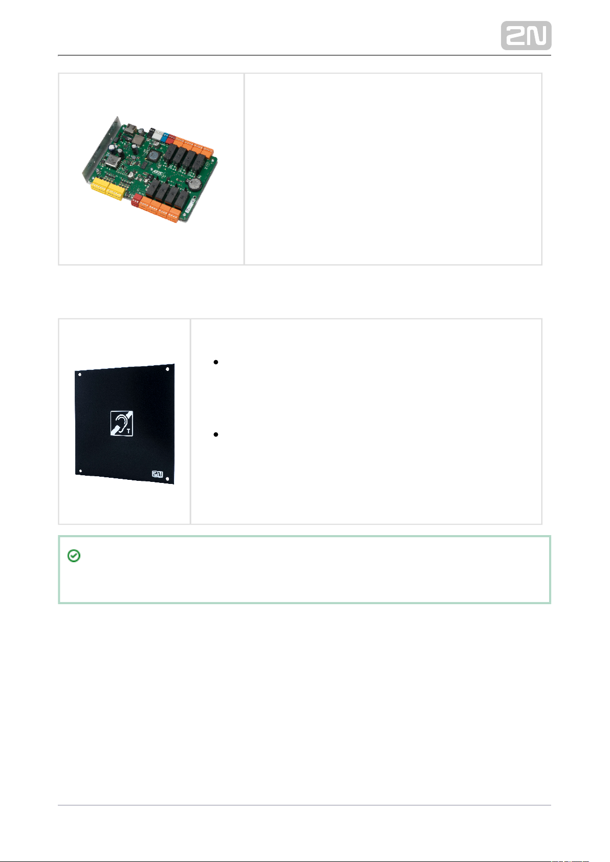
9160501Part No. AXIS A9188 Network I/O relay module
Lift control relay module for up to 8 floors
Induction Loop
Part No. 9159051 Induction loop
An external antenna boosts the range of usability of the
induction loop so that a user wearing a telecoil hearing aid can
receive the audio signal in a wider area. It has to be used with
. A 40 cm long interconnecting cable is Part No. 9155041
included.
Dimensions: 233 (W) x 233 (H) mm
Tip
FAQ: Induction loop – How to connect it with 2N IP intercoms
2N TELEKOMUNIKACE a.s., www.2n.cz 32/105
Page 33
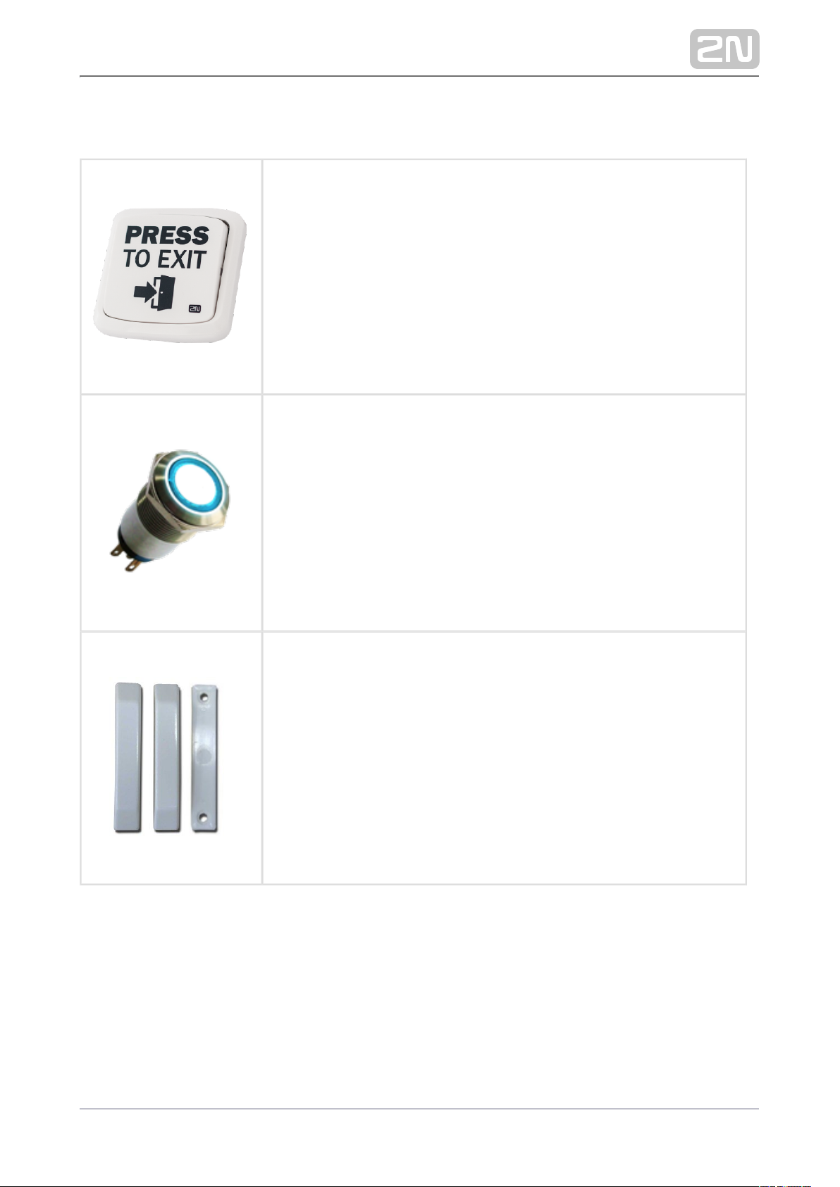
Sensors and Switches
Part No. 9159013 Departure button
Connects the logic input for door unlocking from inside the building.
Part No. 9154004 Water-proof metal button (suitable for the internal RFID card reader)
Part No. 9159012 Magnetic door contact
A door installation set for door opening status identification. Used
where the intercom is used for door protection to detect whether the
door is not closed or forced open.
2N TELEKOMUNIKACE a.s., www.2n.cz 33/105
Page 34
Device Protection
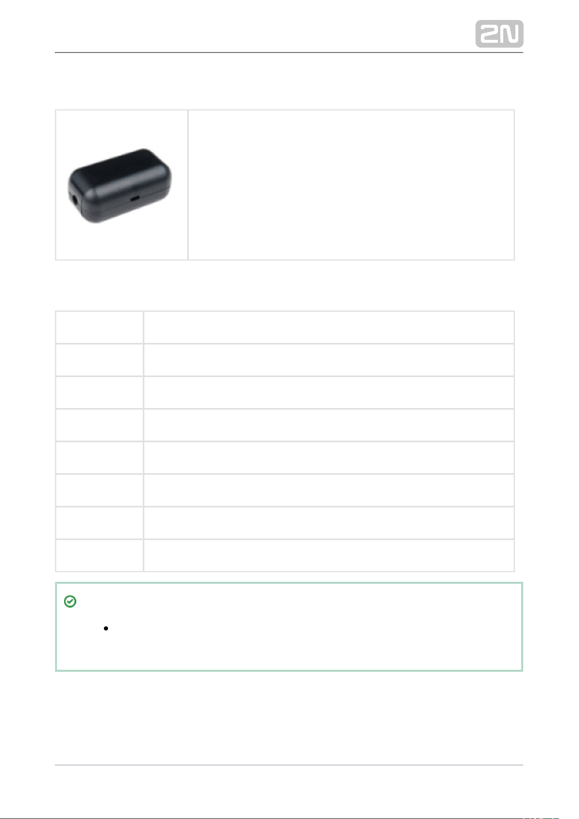
Part No. 9159011 Wiegand Isolator
The is designed for galvanic isolation of two 2N® Wiegand isolator
separately supplied devices interconnected via a Wiegand bus. The
protects the interconnected devices against 2N® Wiegand isolator
communication errors and/or damage.
License
Part No. 9137905 Enhanced Audio
Part No. 9137906 Enhanced Video
PartNo. 9137907 Enhanced Integration
Part No. 9137908 Enhanced Security
Part No. 9137909 Gold
Part No. 9137910 InformaCast
Part No. 9137915 NFC
Part No. 9137916 Lift Module
Tip
Refer to the Configuration Manual for 2N IP Intercoms, Subs. 3.2
for details.Function Licensing
2N TELEKOMUNIKACE a.s., www.2n.cz 34/105
Page 35
Tip
Please refer to the local 2N distributor for more accessories and
recommendations.
2N TELEKOMUNIKACE a.s., www.2n.cz 35/105
Page 36
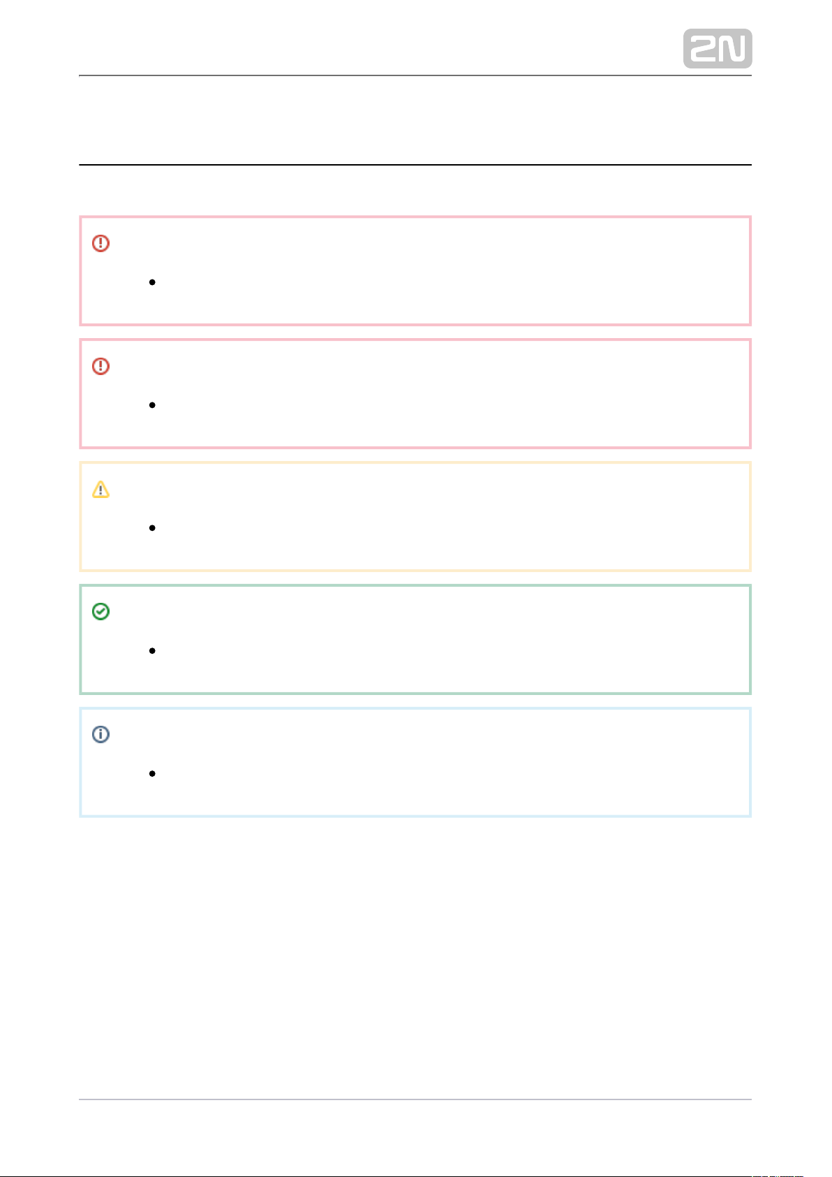
1.2 Terms and Symbols
The following symbols and pictograms are used in the manual:
Safety
Always abide by this information to prevent persons from injury.
Warning
Always abide by this information to prevent damage to the device.
Caution
Important information for system functionality.
Tip
Useful information for quick and efficient functionality.
Note
Routines or advice for efficient use of the device.
2N TELEKOMUNIKACE a.s., www.2n.cz 36/105
Page 37

2. Description and Installation
Here is what you can find in this section:
2.1 Before You Start
2.2 Mechanical Installation
2.3 Electric Installation
2.4 Extending Module Connection
2N TELEKOMUNIKACE a.s., www.2n.cz 37/105
Page 38

2.1 Before You Start
Product Completeness Check
Before you start the installation, check whether the contents of your 2N IP Style
®
package complies with the following list:
1x 2N IP Style
®
1x Brief Manual
1x Certificate of Ownership
2N TELEKOMUNIKACE a.s., www.2n.cz 38/105
Page 39
2.2 Mechanical Installation
2N IP Style® is designed for surface or flush mounting. Additional accessories are
required for each type of installation, which are not part of the main unit package.
The recommended height is 100–150 cm for standard installations and 100–120 cm for
disabled persons from the floor to the device camera level. The installation height may
vary depending on the device use.
2.2.1 Chassis Installation
2.2.2 Mounting Box Installation
2N ® IP Style Main Unit Installation
2N TELEKOMUNIKACE a.s., www.2n.cz 39/105
Page 40
2N TELEKOMUNIKACE a.s., www.2n.cz 40/105
Page 41
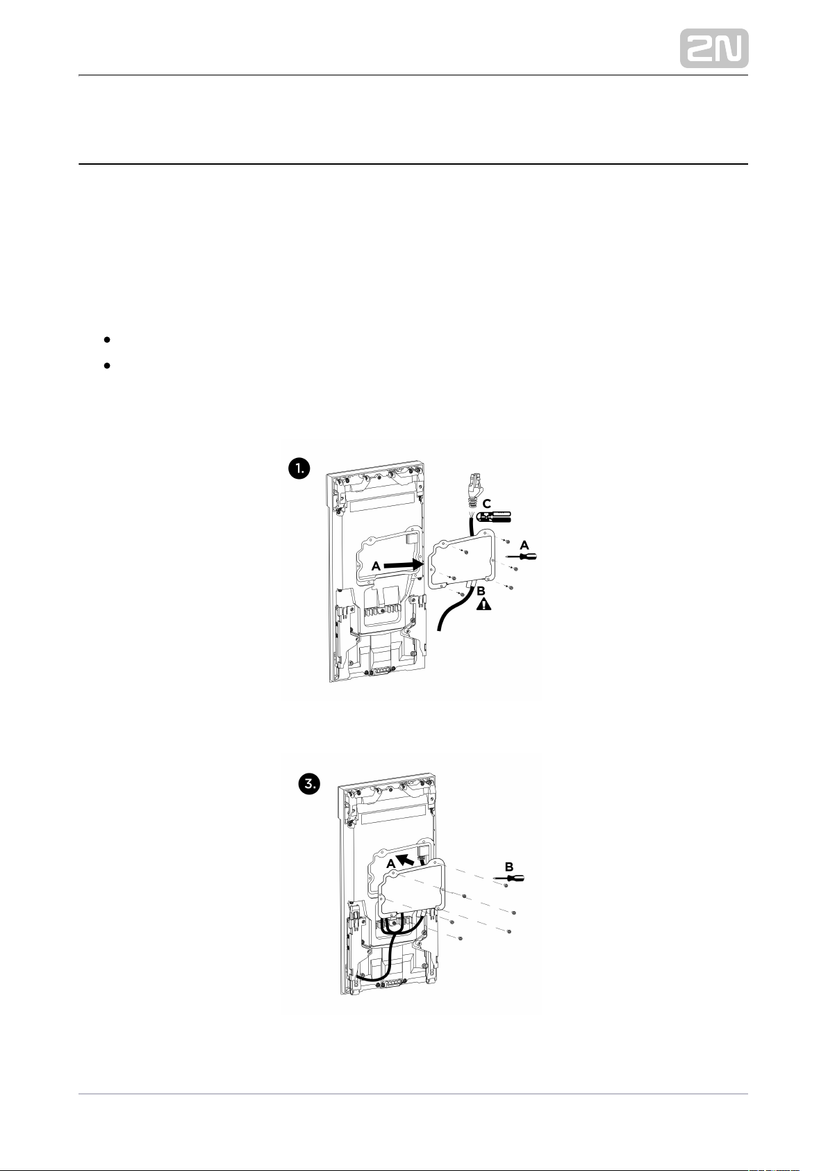
It is assumed that the chassis ( ) or the flush mounting box (2.2.1 Chassis Installation
) and all of the required cables have been installed. The 2.2.2 Mounting Box Installation
recommended length of the accessible cables is 35 cm.
Unscrew the connector cover on the back of the device. Thread all of the
unterminated cables (i.e. without terminals, end pieces, etc.) through the bushing on
the inside of the connector cover. After threading the cables through the bushing, fit
the required end pieces (1).
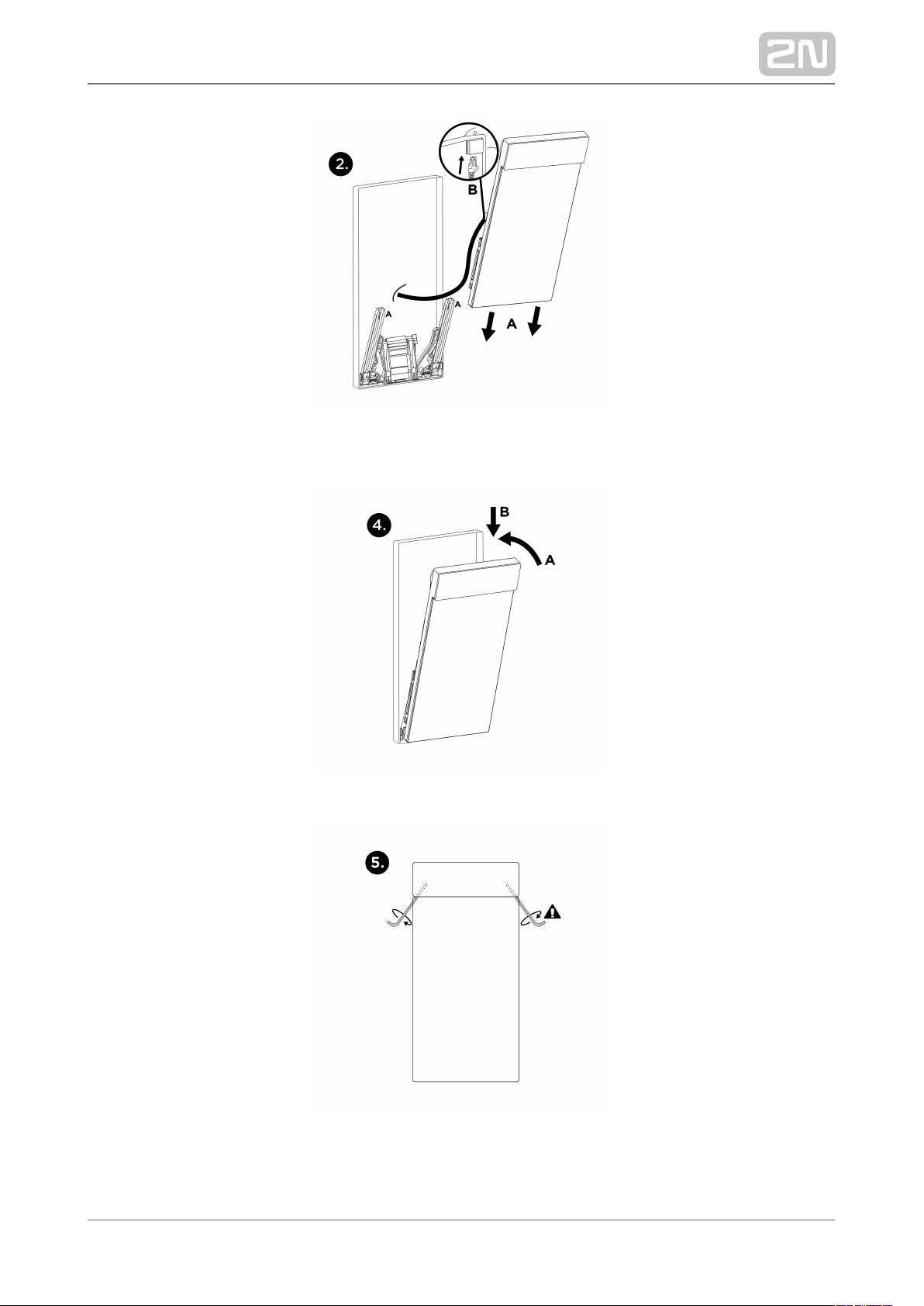
Fold out the mounting bracket located at the bottom of the chassis or flush mounting
box. Fit the profiles on the device back onto the mounting bracket and slide them
down to the lowest possible position, anchoring the device by snapping it into place
(2A).
Connect all the cables to the device (2B). The mounting bracket provides sufficient
support for cable installation and so it is unnecessary to support the device in any
way.
After connecting and securing the superfluous cabling in the clips (3A), screw the
connector cover back on (3B), fold in the device towards the chassis or the flush
mounting box (4A) and then press downwards (4B) to seal the installation.
Now all you have to do is lock the position by tightening the two screws inside the
device using an Allen key (5).
General Mounting Principles
Tip
Select flush mounting where possible. This makes the product elegant
looking, more vandal resistant and more secure.
You are advised to purchase the flush mounting boxes and chassis in
advance and commission a building company to do the masonry for you,
for example.
2N TELEKOMUNIKACE a.s., www.2n.cz 41/105
Page 42
Caution
Before starting the mechanical installation on a selected place, make
sure carefully that the preparations associated with it (drilling, wall
cutting) cannot damage the electrical, gas, water and other existing
wires and pipes.
The warranty does not apply to the product defects and failures arisen
as a result of improper mounting (in contradiction herewith). The
manufacturer is neither liable for damage caused by theft within an area
that is accessible after the attached electric lock is switched on. The
product is not designed as a burglar protection device except when
used in combination with a standard lock, which has the security
function.
When the proper mounting instructions are not met, water might get in
and destroy the electronics. The intercom circuits are constantly under
voltage and water infiltration causes an electro-chemical reaction. The
manufacturer‘s warranty shall be void for products damaged in this way!
Caution
Make sure that the diameters of the dowel holes are accurate. If the
diameters are too large, the dowels may get loose. Use the mounting
glue to secure the dowels if necessary.
Make sure that the depths of the dowel holes are accurate!
Do not use low-quality dowels to avoid their falling out of the wall!
Surface mounting always poses a problem where the installation is
exposed to potential vandalism (such as public garages, etc.). In this
case, use steel anchoring elements instead of the dowels and screws
included in the delivery.
Make sure that the mounting surface is flat with a maximum inequality of
0.5 mm. (e.g. prefabricated boards, glass, cut stone, etc.). If this is not
the case, level the wall surface.
Any intentional mechanical damage to the device (drilling, main unit
tampering, etc.) results in a loss of warranty.
2N TELEKOMUNIKACE a.s., www.2n.cz 42/105
Page 43
Warning
We do not recommend that be installed on sites exposed to 2N IP Style
®
long-time direct sunlight to avoid overheating.
Once overheated, the device is switched off and will be switched on
automatically after it gets colder.
If exposed to direct sunlight or other heat sources, the device gets hot
and may represent a health risk when touched.
2N TELEKOMUNIKACE a.s., www.2n.cz 43/105
Page 44
2.2.1 Chassis Installation
2N TELEKOMUNIKACE a.s., www.2n.cz 44/105
Page 45
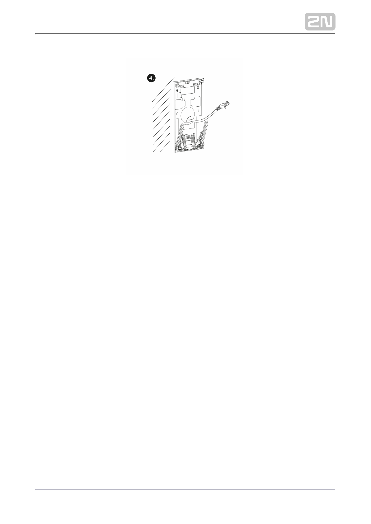
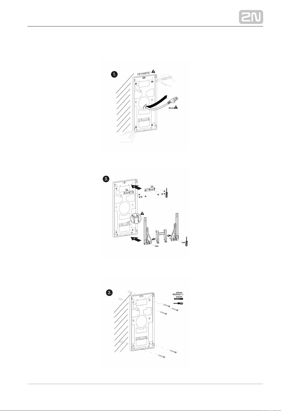
Drill chassis anchoring holes on a proper place. Use the chassis itself as a template to
maintain the horizontal level and carry the cabling at the bottom edge of the cable
hole. The recommended length of the accessible cables is 35 cm (1).
Insert the dowels in the holes drilled and use the screws to anchor the chassis (2).
Put the brackets to the left and right sides of the support handle and fit their positions
using screws (3A).
Fit the lock counterparts to the upper chassis part, hang the handle with the brackets
to the bottom part (4B) and fit all the components using screws (3C).
Now the chassis installation is complete (4).
2N TELEKOMUNIKACE a.s., www.2n.cz 45/105
Page 46
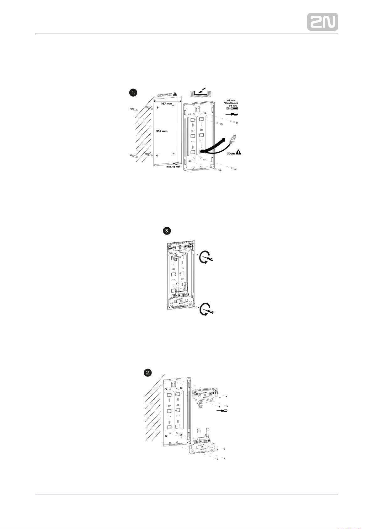
Mounting Box Installation
2N TELEKOMUNIKACE a.s., www.2n.cz 46/105
Page 47
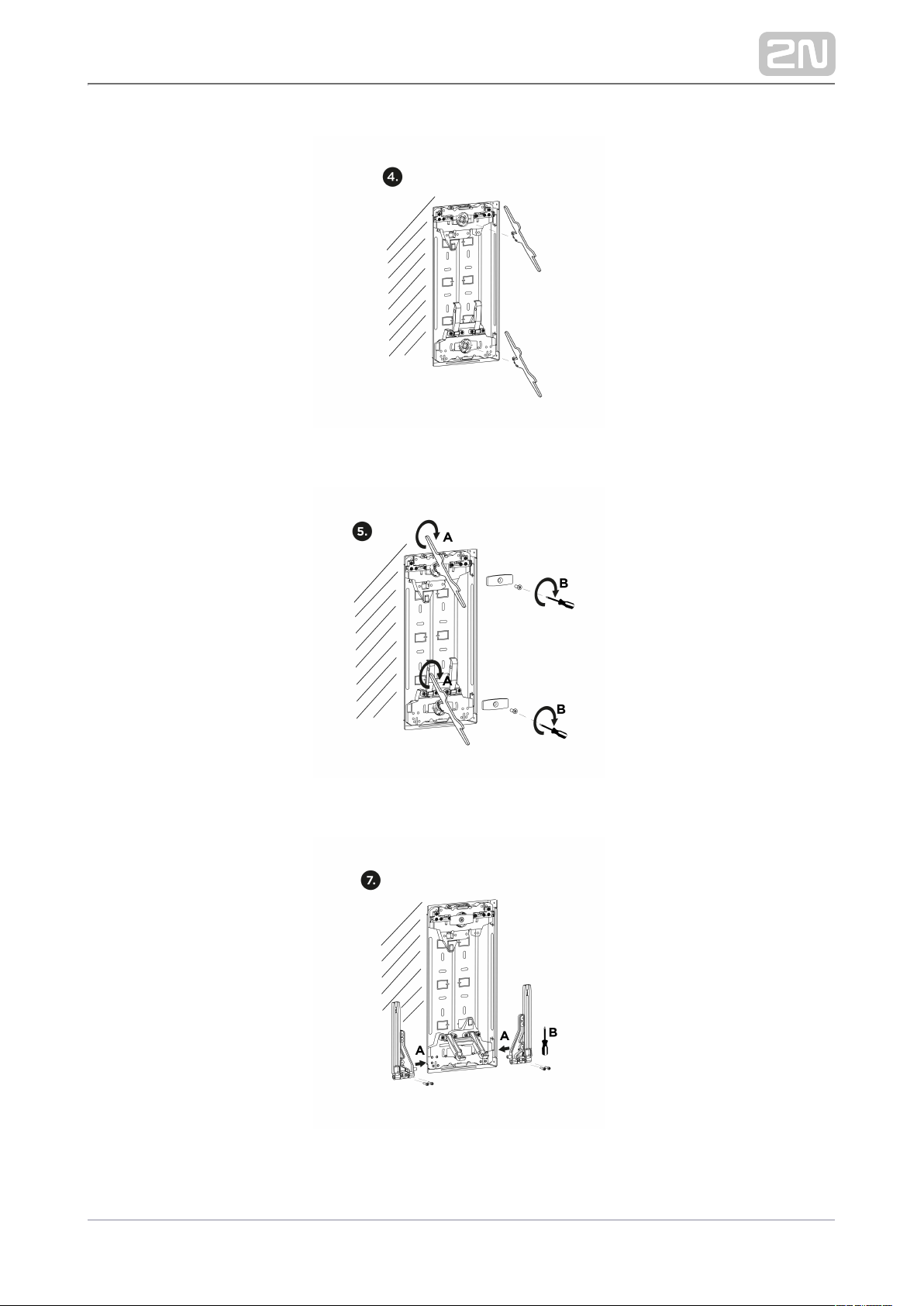
2N TELEKOMUNIKACE a.s., www.2n.cz 47/105
Page 48
Make a hole of the size of 352 (h) x 167 (w) x 45 (d) mm for the mounting box
installation. It is supposed that all the required cables have been carried into the hole.
The recommended length of the accessible cables is 35 cm. Remove the selected
mounting box blank for cabling. Thread the cables through the selected box hole and
put the mounting box in the pre-prepared hole. Make sure that the mounting box hole
is deep enough and that the box edges are aligned with the wall surface. If the hole is
convenient, anchor the box using screws and dowels (1).
Insert the enclosed detents in the riveting nuts. Make sure that the tops of the detents
direct towards the box center against each other. The detent with 2 handles is
intended exclusively for the box bottom installation. Fit the detents with screws (2).
If the position of the detents seems to be too deep, untighten the screw to remove the
detent fixture (3), insert a levelling key in the levelling mechanism grooves and turn it
to adjust the required level (4). The levelling mechanism allows for a shift of up to 8
mm in height.
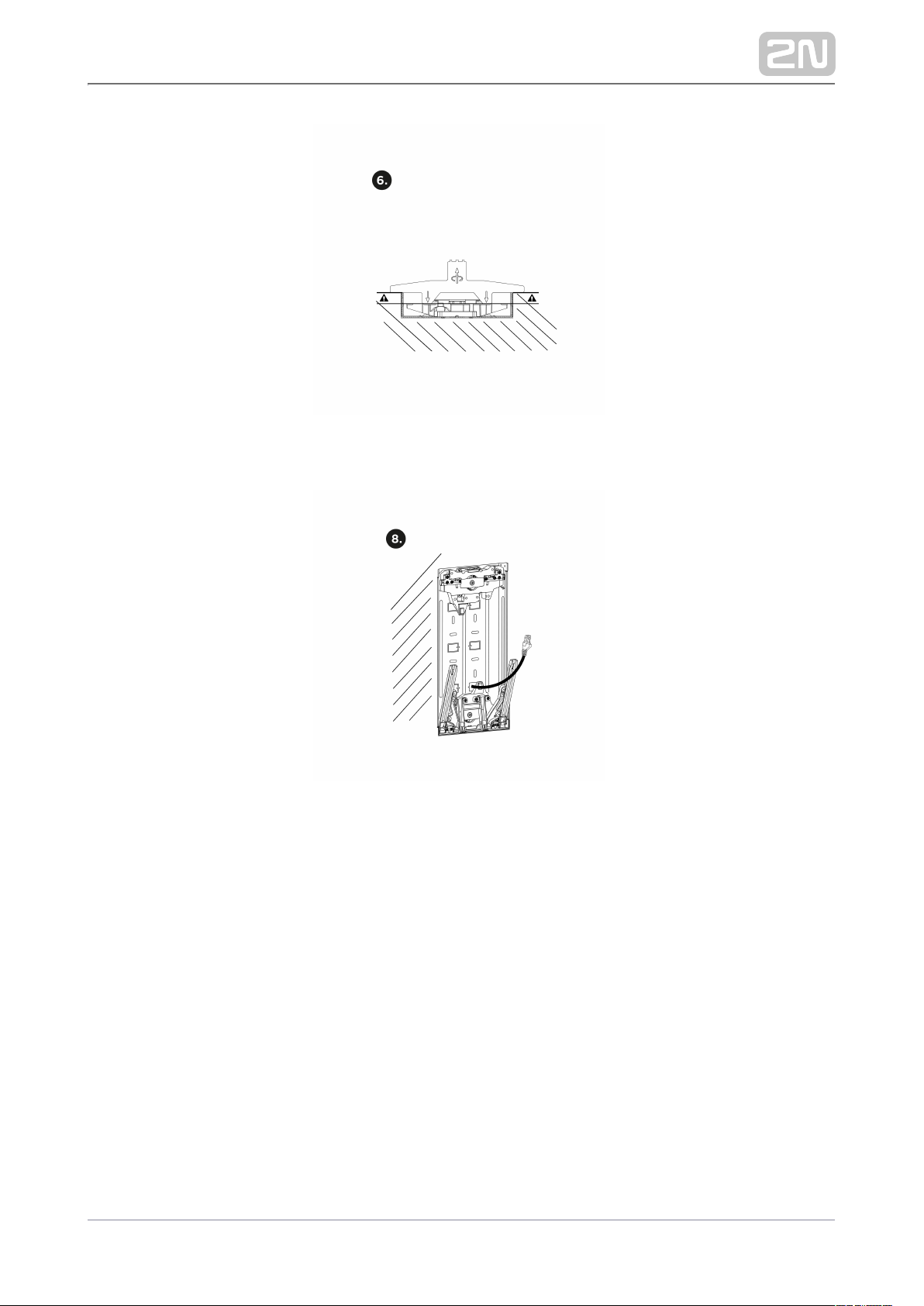
2N TELEKOMUNIKACE a.s., www.2n.cz 48/105
Page 49

After levelling re-anchor the fixture with a screw (5).
Use a levelling key to check the proper height of detent embedding to make sure that
the key is aligned with the mounting box edge and also touches the detent surface
(6).
Put the brackets to the left and right sides of the bottom detent handle (7A) and fit
their positions using screws (7B).
Now the mounting box installation is complete (8).
2N TELEKOMUNIKACE a.s., www.2n.cz 49/105
Page 50
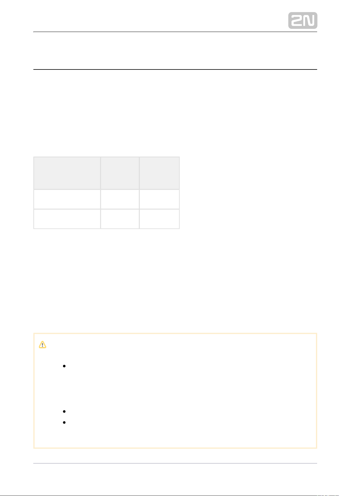
2.3 Electric Installation
2N IP Style® can be fed either from an external 12V / 4 A DC power supply or from a
PoE+ 802.3at supporting LAN.
External Power Supply
For reliability reasons, use a 12 V ±15% SELV supply dimensioned to the current
consumption as required for feeding of the main unit and connected extending
modules.
DC voltage
[V]
Load
[A]
Max power
[W]
12 3 36
12 4 48
PoE+ Supply
2N IP Style® is compatible with the PoE+ 802.3at technology and can be supplied
directly from the LAN via compatible network elements. If your LAN does not support
this technology, insert a PoE injector, , between and the Part No. 91378101 2N IP Style
®
nearest network element. This power supply provides with 21.6 W for 2N IP Style
®
feeding of the main unit and connected modules.
Caution
The PoE power supply cannot provide with a full 2N IP Style
®
functionality as it only offers a limited mode (Low Power Mode) for basic
configuration. This way of feeding is not recommended. Connect the
device to a PoE+ supply or a convenient DC supply and restart the
device.
The PoE power supply detection is performed during the device restart.
If the PoE power supply is used and the Low Power Mode is on, all
configuration sections show a feeding problem warning.
2N TELEKOMUNIKACE a.s., www.2n.cz 50/105
Page 51
Combined Power Supply
2N IP Style® can be fed from an external power supply and PoE+ at the same time. In
this mode, the maximum power of 48 W (if a 12V / 4A DC external supply is used) or
36 W (if a 12V / 3A DC supply is used) is available for feeding the main unit and
connected modules.
Warning
In case the external power supply is disconnected / fails during the
combined external / PoE feeding, the device will get restarted. The
device will run in the Low Power Mode and a feeding problem warning
will be displayed in all of the configuration sections.
Reconnect the device to an external power supply or Poe+ and force
restart to recover the full functionality.
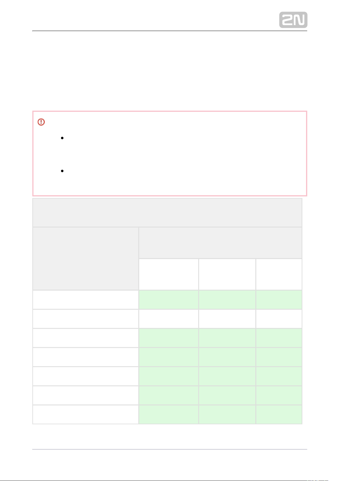
Main Unit Max Power Overview
Main Unit Consumption [W]
(Maximum value)
mA
(from 12V supply)
W
(from 12V supply)W(from PoE+)
At relax 505 6.06 7.13
Restart 700 8.4 9.88
Infrared light (100%) 655 1.8 2.12
Display backlight intensity (100%) 950 4.8 5.65
Audio (100 %) 1420 10.98 12.92
Video motion detection 20 0.24 0.28
OUTPUT 600 7.2 8.47
2N TELEKOMUNIKACE a.s., www.2n.cz 51/105
Page 52
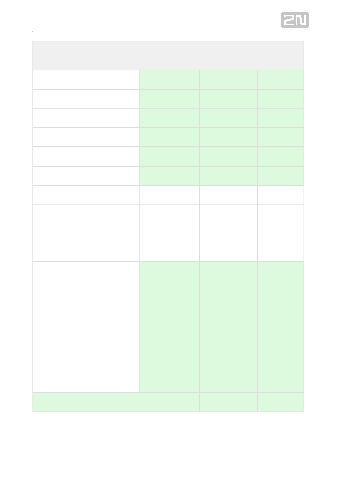
Main Unit Max Power Overview
RFID ON 550 0.54 0.64
Pictogram backlight (100 %) 570 0.24 0.28
Video streaming (ON) 530 0.3 0.35
CPU (100 %) 50 0.6 0.71
Memory (100 %) 25 0.3 0.35
GPU (100 %) 50 0.6 0.71
1 x Stream (H.265, 2560 x 1440) 30 0.36 0.42
3 x Stream
H.265 (2560 x 1440)
H.264 (1920 x 1088)
MJPEG (1280 x 720)
50 0.6 0.71
9 x Stream
H.265 (2560 x 1440)
H.256 (1920 x 1088)
H.265 (1280 x 720)
H.264 (2560 x 1440)
H.254 (1920 x 1088)
H.264 (1280 x 720)
MJPEG (2560 x 1440)
MJPEG (1920 x 1088)
MJPEG (1280 x 720)
80 0.96 1.13
Maximum Power Consumption 35.16 41.38
2N TELEKOMUNIKACE a.s., www.2n.cz 52/105
Page 53
LAN Connection
2N IP Style ®is connected to the Local Area Network (LAN) via the UTP/STP cable
(Cat 5e or higher) terminated with an RJ-45 (LAN) connector. As the device is
equipped with the Auto-MDIX function, you can use either the straight or crossed
cable version.
Caution
We recommend the use of a LAN surge protection.
We recommend that an SSTP Ethernet cable with a shielded RJ-45
connector is used, which is connected to the switch (with the grounding
option) using the same shielded connector. Thus, the device is grounded
without the need to use grounding terminals.
Tip
Remove the protective connector cover to facilitate the threading of the
UTP/STP cable RJ terminal into the device box.
2N TELEKOMUNIKACE a.s., www.2n.cz 53/105
Page 54
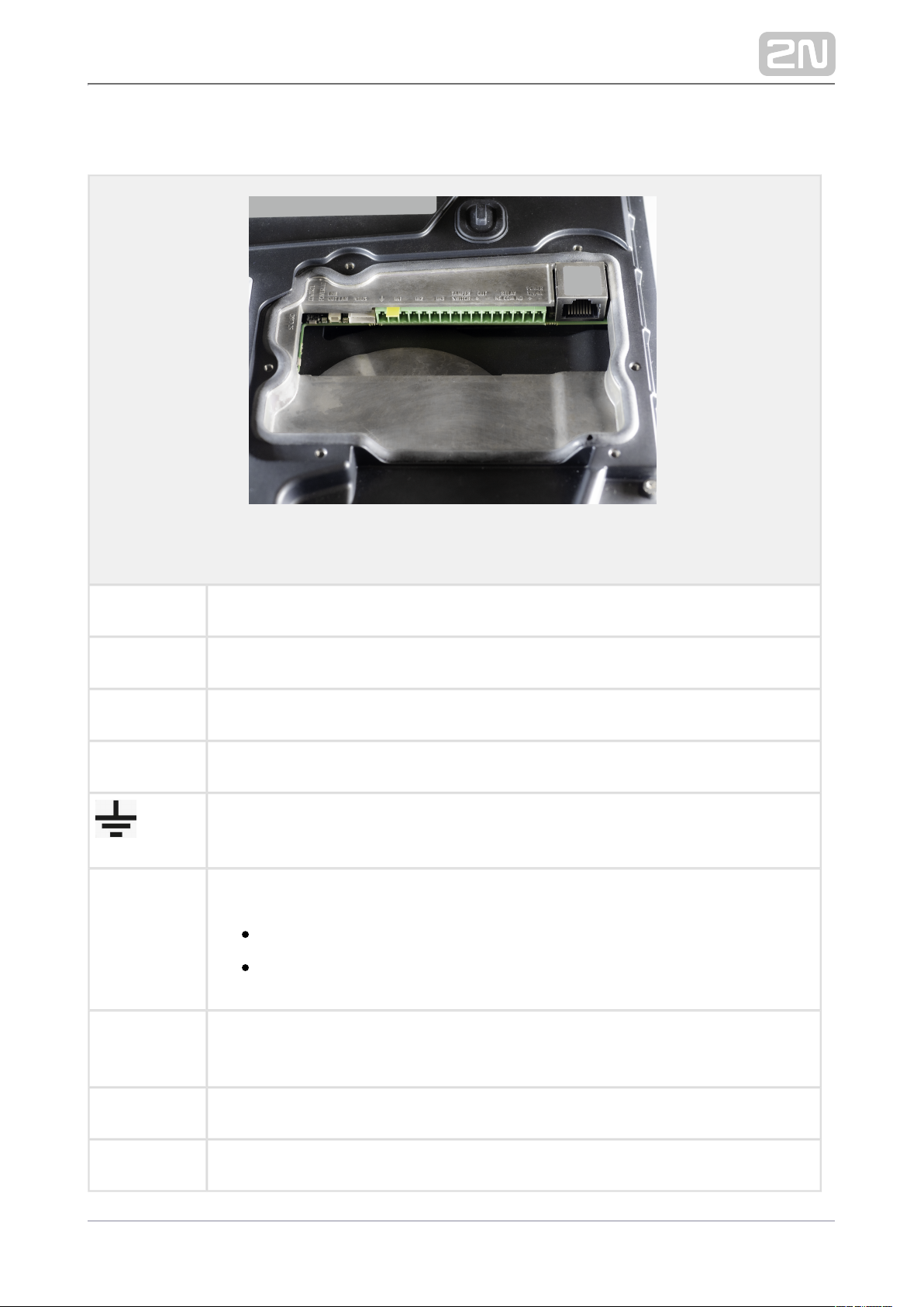
Main Unit Connectors
Legend to the figure
CONTROL Factory reset button
POWERLED Device status LED
LAN LAN connection status LED
VBUS Bus connector
Grounding terminal
IN1, IN2, IN3 Input terminals in passive / active mode ( 30 V to +30 V DC)−
OFF = open contact OR U IN> 1.5 V
ON = closed contact OR U < 1.5 V
IN
TAMPER
SWITCH
Security system connecting terminals (on the back side above the connectors)
OUT 12 V / 0.6 A DC active output
RELAY 30 V / 1 A AC/DC NO/NC contact terminals
2N TELEKOMUNIKACE a.s., www.2n.cz 54/105
Page 55
POWER 12 V
/ 4 A
External 12 V / 4 A DC power supply terminals
LAN
connector
Optionally PoE+ 802.3at for device LAN connection
Tamper
Switch
Switch detecting unauthorized device opening
SD CARD SD card slot
Caution
We recommend that a grounding cable of the cross-section of 1.5 mm
2
is used.
2N TELEKOMUNIKACE a.s., www.2n.cz 55/105
Page 56
Available Switches
Location Name Description
Basic Unit RELAY Passive switch: make and break contact, up to 30 V / 1 A AC/DC Used for
connection of non-critical devices only (lights, e.g.).
OUT Active switch output: 8 to 12 V DC according to power supply (PoE: 10 V;
adapter: source voltage minus 2 V), up to 400 mA
Modul I
/O*
(Part No.
9155034)
ext.
relay1
Passive switch: make and break contact, up to 30 V / 1 A AC/DC Used for
connection of non-critical devices only (lights, e.g.).
ext.
relay2
Passive switch: make and break contact, up to 30 V / 1 A AC/DC Used for
connection of non-critical devices only (lights, e.g.).
You can use any number of the modules marked with *.
2N TELEKOMUNIKACE a.s., www.2n.cz 56/105
Page 57
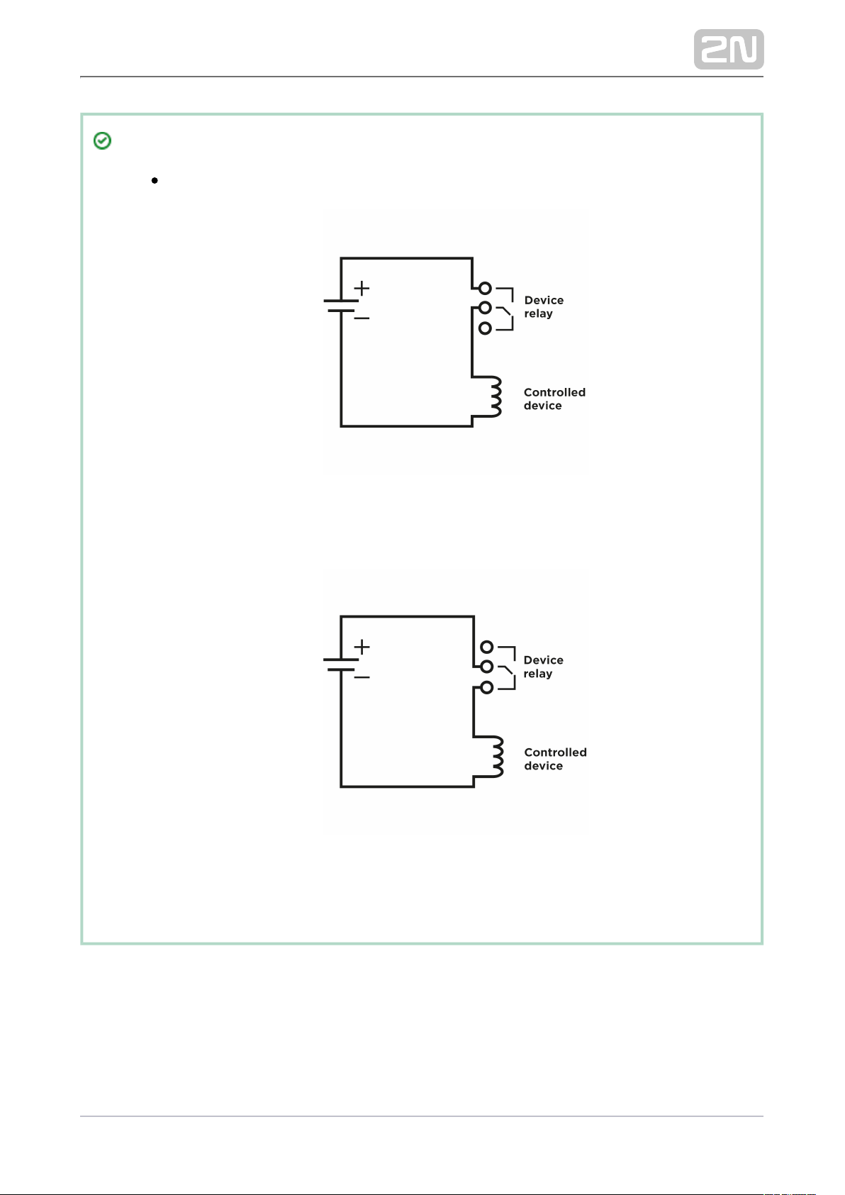
Tip
Relay output wiring diagram
Wiring diagram for making of the electric circuit of the device to be
controlled
Wiring diagram for breaking of the electric circuit of the device to be
controlled
2N TELEKOMUNIKACE a.s., www.2n.cz 57/105
Page 58
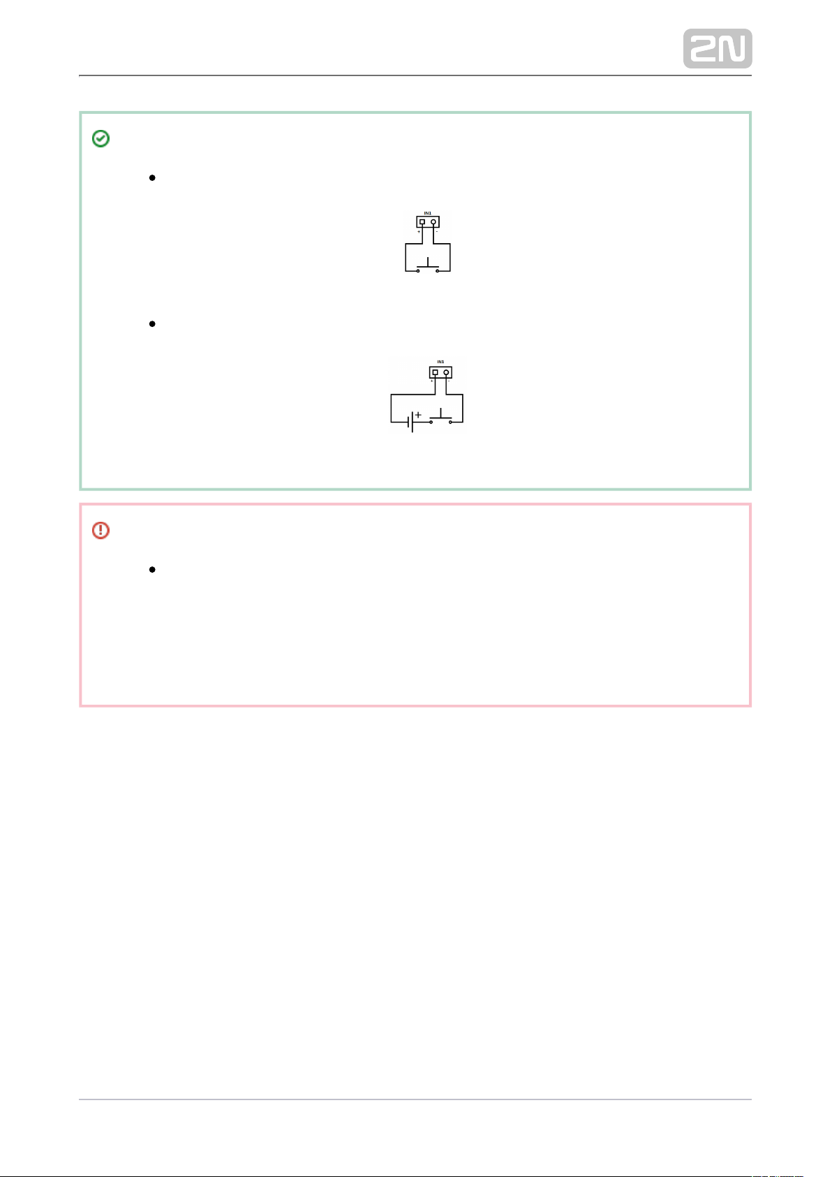
Tip
Wiring Diagram of IN1 connector in active mod
Wiring Diagram of IN1 connector in passive mod
Security
The 12V output is used for lock connection. If, however, the unit (2N IP
Intercom, 2N Access Unit) is installed where unauthorized tampering
may happen (building envelopes), we strongly recommend that 2N
®
Security Relay (Part No. 9159010) be used for enhanced installation
security.
2N TELEKOMUNIKACE a.s., www.2n.cz 58/105
Page 59
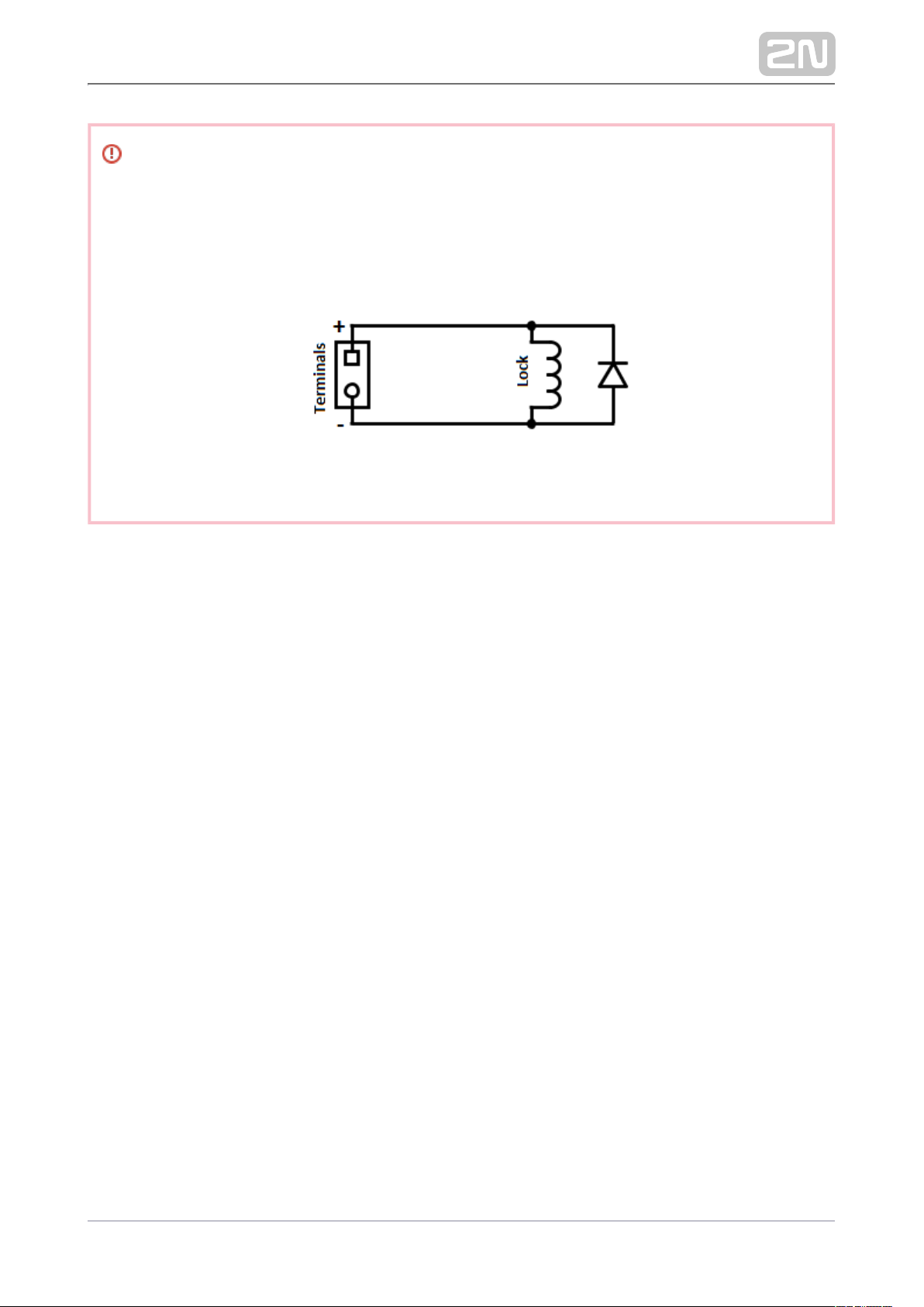
Warning
If a coil containing device is connected, e.g. a relay / electromagnetic lock, it is
necessary to protect the intercom output against voltage peak while switching
off the induction load. For this way of protection, we recommend a 1 A / 1000
V diode (e.g., 1N4007, 1N5407, 1N5408) connected antiparallel to the device.
2N TELEKOMUNIKACE a.s., www.2n.cz 59/105
Page 60
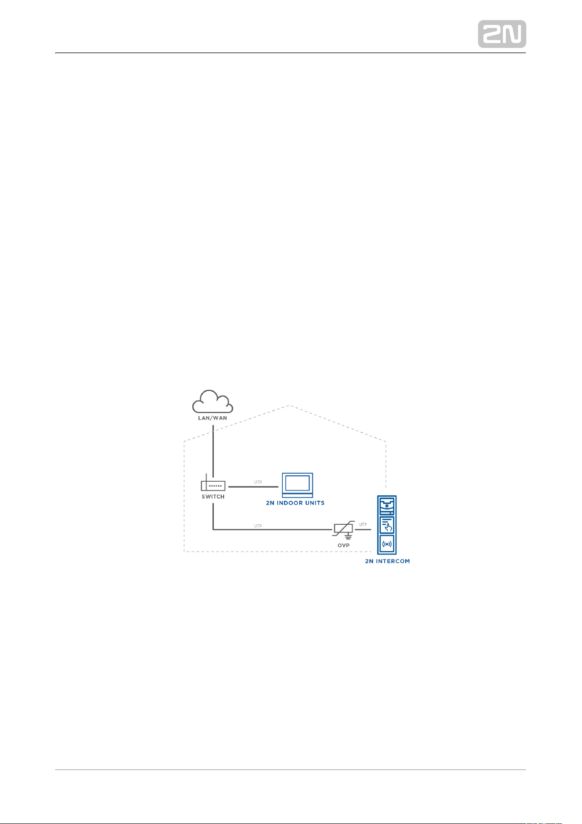
2.3.1 Overvoltage Protection
Recommendations for Additional Overvoltage Protection Installation
If running:
a) outside a building,
b) on/in an outer wall or roof,
the 2N device wiring may be exposed to atmospheric effects resulting in overvoltage
that may subsequently damage any devices installed outside the building, on its outer
wall or roof. Overvoltage may damage devices connected to these wires and installed
inside the building as well. Therefore, we recommend that additional surge protectors
be installed on all the wires leading outside buildings, on outer walls or roofs, namely:
a) as close as possible to the device installed outside the building or on its outer wall
/roof,
b) as close as possible to the point where the wires leave the building.
Examples of Overvoltage Protection Installation:
2N TELEKOMUNIKACE a.s., www.2n.cz 60/105
Page 61
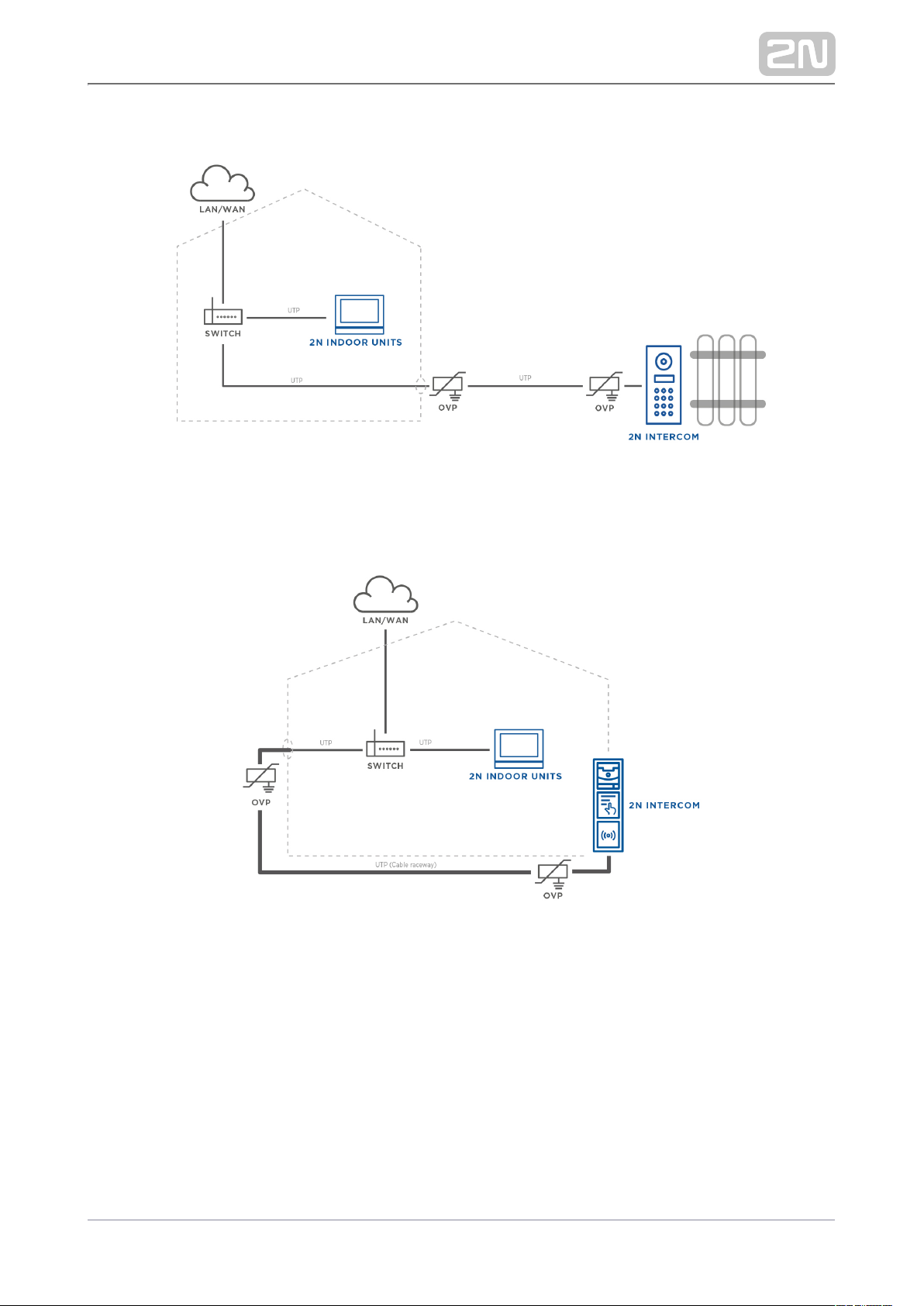
OVP = overvoltage protection
2N TELEKOMUNIKACE a.s., www.2n.cz 61/105
Page 62
2.4 Extending Module Connection
The functions can be extended by connecting any of the available 2N IP 2N IP Style
® ®
Verso extending modules via the VBUS connector. Choose the proper accessories for
each type of extending module installation.
Info Panel
125 kHz RFID card reader
13.56 MHz NFC RFID card reader
Secured 13.56 MHz NFC RFID card reader
125 kHz, 13.56 MHz, NFC Bluetooth & RFID reader
125 kHz, secured 13.56 MHz, NFC Bluetooth & RFID reader
Bluetooth reader
Induction loop
Fingerprint scanner
I/O module
Wiegand module
Tamper switch
Security relay
Module Bus Interconnection
All the extending modules, except for the tamper switch, are interconnected via a bus.
The bus starts on the basic unit and goes over all the modules. The order of modules
on the bus is irrelevant. And it also irrelevant which bus connector on the module is
used as the input and which is used as the output.
The modules include a 220 mm long interconnecting cable, the Wiegand (9155037)
and I/O modules include an 80 mm long bus cable.(9155034)
It is possible to order separate bus cables of the length of 1 m, 3 m or 5 m (Part No.
), which are intended for remote module 9155050/9155054/9155055 respectively
installations. Typically, they help install an RFID card reader on the opposite side of
the wall on which is installed. This cable may only be used once on the 2N IP Style
®
bus. The total length of all the bus cables used in these extended installations may not
exceed 7 m.
2N TELEKOMUNIKACE a.s., www.2n.cz 62/105
Page 63
Caution
Purchase a frame / mounting box for the extending modules to be
connected according to the type of installation. This does not apply to
the I/O, Wiegand and tamper switch extending modules.
Module Power Supply
All the modules, except for the tamper switch, are powered from a bus. 2N IP Style
®
The available bus power output depends on the power supply type. The basic unit can
use a 4A power supply to increase the power available to the modules connected.
Power supply Specification Available power output
External supply 12 V ±15 % / 4 A DC up to 48
PoE+ 802.3at up to 21.6 W
Combined External supply + PoE+
Infopanel Module
The Infopanel module ( ) is one of the 2N IP Verso system elements Part No. 9155030
®
and is used for inserting and backlighting the printed information.
The module contains two bus connectors.2N IP Style
®
These two connectors are fully interchangeable and can be used either as inputs
from the basic unit or outputs to other modules.
If this module is the last one on the bus, one of the connectors remains
unconnected.
The module package includes a 220 mm long interconnecting cable.
Name tag dimensions: 69.2 (W) x 86.7 (H) mm (dimensional tolerance: +0; 0.5 −
mm).
Refer to for the printing template.www.2n.cz
2N TELEKOMUNIKACE a.s., www.2n.cz 63/105
Page 64
125 kHz RFID Card Reader Module
The 125 kHz RFID card reader ( ) is one of the 2N IP Verso system Part No. 9155032
®
elements and is used for reading RFID card IDs in the 125 kHz band.
The module contains two bus connectors.2N IP Style
®
These two connectors are fully interchangeable and can be used either as inputs
from the basic unit or outputs to other modules.
If this module is the last one on the bus, one of the connectors remains
unconnected.
The module package includes a 220 mm long interconnecting cable.
The following RFID cards can be read:
EM4xxx
Caution
We recommend that the M-Bus and LAN cables are not crossed but
carried separately through one bushing to increase the reading distance
of this reader if combined with a touch display in a single installation.
2N TELEKOMUNIKACE a.s., www.2n.cz 64/105
Page 65
13.56 MHz RFID Card Reader Module
The 13.56 MHz RFID card reader ( ) is one of the 2N IP Verso system Part No. 9155040
®
elements and is used for reading RFID card IDs in the 13.56 MHz band.
The module contains two bus connectors.2N IP Style
®
These two connectors are fully interchangeable and can be used either as inputs
from the basic unit or outputs to other modules.
If this module is the last one on the bus, one of the connectors remains
unconnected.
The module package includes a 220 mm long interconnecting cable.
The following RFID cards can be read:
ISO14443A (Mifare, DESFire)
PicoPass (HID iClass)
FeliCa
ST SR(IX)
2N Mobile Key
®
Secured 13.56 MHz NFC RFID Card Reader
The 13.56 MHz RFID card reader ( ) is one of the 2N IP Verso system Part No. 9155086
®
elements and is used for reading secured RFID card IDs in the 13.56 MHz band.
The module contains two bus connectors.2N IP Style
®
These two connectors are fully interchangeable and can be used either as inputs
from the basic unit or outputs to other modules.
If this module is the last one on the bus, one of the connectors remains
unconnected.
The module package includes a 220 mm long interconnecting cable.
The following RFID cards can be read:
ISO14443A (Mifare, DESFire)
PicoPass (HID iClass)
FeliCa
ST SR(IX)
2N Mobile Key
®
2N TELEKOMUNIKACE a.s., www.2n.cz 65/105
Page 66
HID SE (Seos, iClass SE, Mifare SE)
125 kHz, 13.56 MHz NFC Bluetooth & RFID Reader
A combined Bluetooth and 125 kHz and 13.56 MHz card reader module (Part No.
) is one of the 2N IP Verso system elements and is used for smartphone/9155082
®
2N
®
tablet/card access control, making user calls and/or other functions.Mobile Key
NFC – a licensed function, for Mobile Key for Android only.2N Mobile Key
®
The module contains two bus connectors.2N IP Style
®
These two connectors are fully interchangeable and can be used either as inputs
from the basic unit or outputs to other modules.
If this module is the last one on the bus, one of the connectors remains
unconnected.
The module package includes a 220 mm long interconnecting cable.
The following RFID cards can be read:
125 kHz
EM4xxx
13.56 MHz
ISO14443A (Mifare, DESFire)
PicoPass (HID iClass)
FeliCa
ST SR(IX)
2N Mobile Key
®
Tip
To accelerate access card reading, you are recommended to select the
card types used by the user in the module settings.
2N TELEKOMUNIKACE a.s., www.2n.cz 66/105
Page 67
Caution
supports connection of just one Bluetooth module. If 2N IP Style
®
connected, multiple Bluetooth modules may result in a undesired
behavior.
125 kHz, Secured 13.56 MHz, NFC Bluetooth & RFID Reader
A combined Bluetooth and 125 kHz and secured 13.56 MHz card reader module (Part
) is one of the 2N IP Verso system elements and is used for smartphone/No. 9155084
®
tablet/card access control, making user calls and/or other functions.2N Mobile Key
®
NFC – a licensed function, for Mobile Key for Android only.2N Mobile Key
®
The module contains two bus connectors.2N IP Style
®
These two connectors are fully interchangeable and can be used either as inputs
from the basic unit or outputs to other modules.
If this module is the last one on the bus, one of the connectors remains
unconnected.
The module package includes a 220 mm long interconnecting cable.
The following RFID cards can be read:
125 kHz
EM4xxx
13.56 MHz
ISO14443A (Mifare, DESFire)
PicoPass (HID iClass)
FeliCa
ST SR(IX)
2N Mobile Key
®
HID SE (Seos, iClass SE, Mifare SE)
2N TELEKOMUNIKACE a.s., www.2n.cz 67/105
Page 68
Tip
To accelerate access card reading, you are recommended to select the
card types used by the user in the module settings.
Caution
supports connection of just one Bluetooth module. If 2N IP Style
®
connected, multiple Bluetooth modules may result in a undesired
behavior.
Bluetooth Reader Module
The Bluetooth reader ( ) is one of the 2N IP Verso system elements Part No. 9155046
®
and helps authenticate users and subsequently open doors using Android and iOS
based smartphones via the Bluetooth protocol 4.0, thus replacing the RFID cards.
Make sure that 2N Mobile Key is installed available from and to
®
Google Play Appstore
make authentication work properly. The application requires phones with Android OS
6 and higher and iOS 12 and higher.
The module contains two bus connectors.2N IP Style
®
These two connectors are fully interchangeable and can be used either as inputs
from the basic unit or outputs to other modules.
If this module is the last one on the bus, one of the connectors remains
unconnected.
The module package includes a 220 mm long interconnecting cable.
The module uses the 2.4 GHz frequency.
IDs from the following Bluetooth 4.0 supporting smartphones can be read:
Android 6 and higher
iOS 12 and higher
2N TELEKOMUNIKACE a.s., www.2n.cz 68/105
Page 69
Caution
supports connection of just one Bluetooth module. If 2N IP Style
®
connected, multiple Bluetooth modules may result in a undesired
behavior.
Induction Loop Module
The Induction loop module ( ) is one of the 2N IP Verso system Part No. 9155041
®
elements and is used form transmitting audio signals directly into a hearing aid via a
magnetic field.
The module contains two bus connectors.2N IP Style
®
These two connectors are fully interchangeable and can be used either as inputs
from the basic unit or outputs to other modules.
If this module is the last one on the bus, one of the connectors remains
unconnected.
The module package includes a 220 mm long interconnecting cable.
Used mode: T
Maximum power: 2 W
Frequency range: 100 Hz – 5 kHz / ± 3 dB
External antenna ( ) connection optionPart No. 9155043
Antenna output short circuit resistance: without limitation
Fingerprint Scanner Module
The Fingerprint scanner ( ) is one of the 2N IP Verso system Part No. 9155045
®
elements and is used for verification of human fingerprints for access control and
intercom / third party equipment control.
The module contains two bus connectors.2N IP Style
®
These two connectors are fully interchangeable and can be used either as inputs
from the basic unit or outputs to other modules.
If this module is the last one on the bus, one of the connectors remains
unconnected.
The module package includes a 220 mm long interconnecting cable.
2N TELEKOMUNIKACE a.s., www.2n.cz 69/105
Page 70
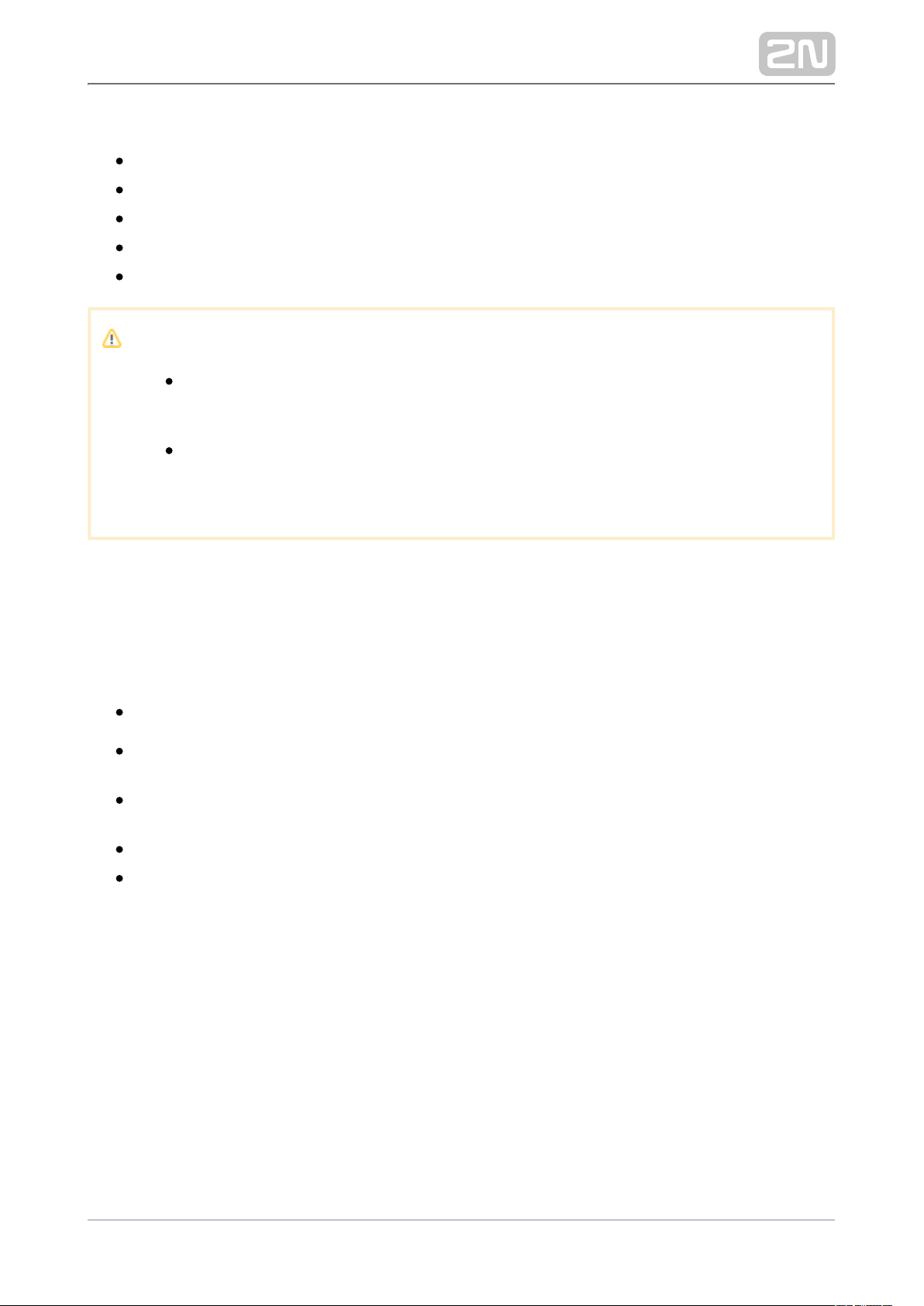
Important module properties:
FBI PIV and Mobile ID certification – FAP20
Durable glass touch surface
Rejection of spoof fingerprints
Operating temperature range: 20 to 55 ºC−
0–90 % relative humidity, noncondensing
Caution
A higher moisture may deteriorate the finger papillary line scanning. You
are advised to dry your finger and the reader scanning surface for
successful authentication.
Fingerprint scanning may be more difficult for seniors whose finger
papillary lines are not so distinctive (skin elasticity drops with age and a
higher scanning pressure may lead to fingerprint blurring).
I/O Module
The I/O module ( ) is one of the 2N IP Verso system elements and is Part No. 9155034
®
used for extending the number of inputs and outputs.
The module contains two bus connectors.2N IP Style
®
These two connectors are fully interchangeable and can be used either as inputs
from the basic unit or outputs to other modules.
If this module is the last one on the bus, one of the connectors remains
unconnected.
The module package includes a 80 mm long interconnecting cable.
The inputs / outputs are addressed as follows: <module_name>.<input
, e.g. module5.relay1. Configure the module name in the Module /output_name>
name parameter in Hardware / Extending modules.
2N TELEKOMUNIKACE a.s., www.2n.cz 70/105
Page 71
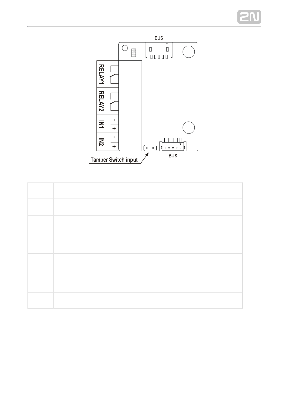
RELAY1 RELAY1 terminals with accessible 30 V / 1 A AC/DC NO/NC contact
RELAY2 RELAY2 terminals with accessible 30 V / 1 A AC/DC NO/NC contact
IN1 IN1 terminals for input in passive / active mode ( 30 V to +30 V DC)−
OFF = open contact or U > 1.5 V
IN
ON = closed contact or U < 1.5 V
IN
IN2 IN2 terminals for input in passive / active mode ( 30 V to +30 V DC)−
OFF = open contact or U > 1.5 V
IN
ON = closed contact or U < 1.5 V
IN
TAMPER Tamper switch (9155038) input
2N TELEKOMUNIKACE a.s., www.2n.cz 71/105
Page 72

Wiegand Module
The Wiegand module ( ) is one of the 2N IP Verso system elements Part No. 9155037
®
and is used for connecting an external Wiegand device (RFID card reader, fingerprint
/ biometric data scanner) and/or connecting the intercom to an external security
exchange. All the inputs and outputs are galvanically isolated from the intercom with
the insulation strength of 500 V DC. It is necessary to feed +U IN on Wiegand OUT
from the Control Panel.
Reader – connects an external Wiegand-supporting reader. The reader sends
information on the intercom card number.
Control Panel – used for connection to the security PBX / access system to
which the intercom sends the card number information.
The module contains two bus connectors.2N IP Style
®
These two connectors are fully interchangeable and can be used either as inputs
from the basic unit or outputs to other modules.
If this module is the last one on the bus, one of the connectors remains
unconnected.
The module package includes a 80 mm long interconnecting cable.
Configure the module name in the Module name parameter in the Hardware /
Extending modules menu.
The LED IN input is addressed as follows: , e.g. <module_name>.<input1>
module2.input1.
The Tamper input is addressed as follows: , e.g. <module_name>.<tamper>
module2.tamper.
The LED OUT output (negated) is addressed as follows: <module_name>.
, e.g. module2.output1.<output1>
2N TELEKOMUNIKACE a.s., www.2n.cz 72/105
Page 73
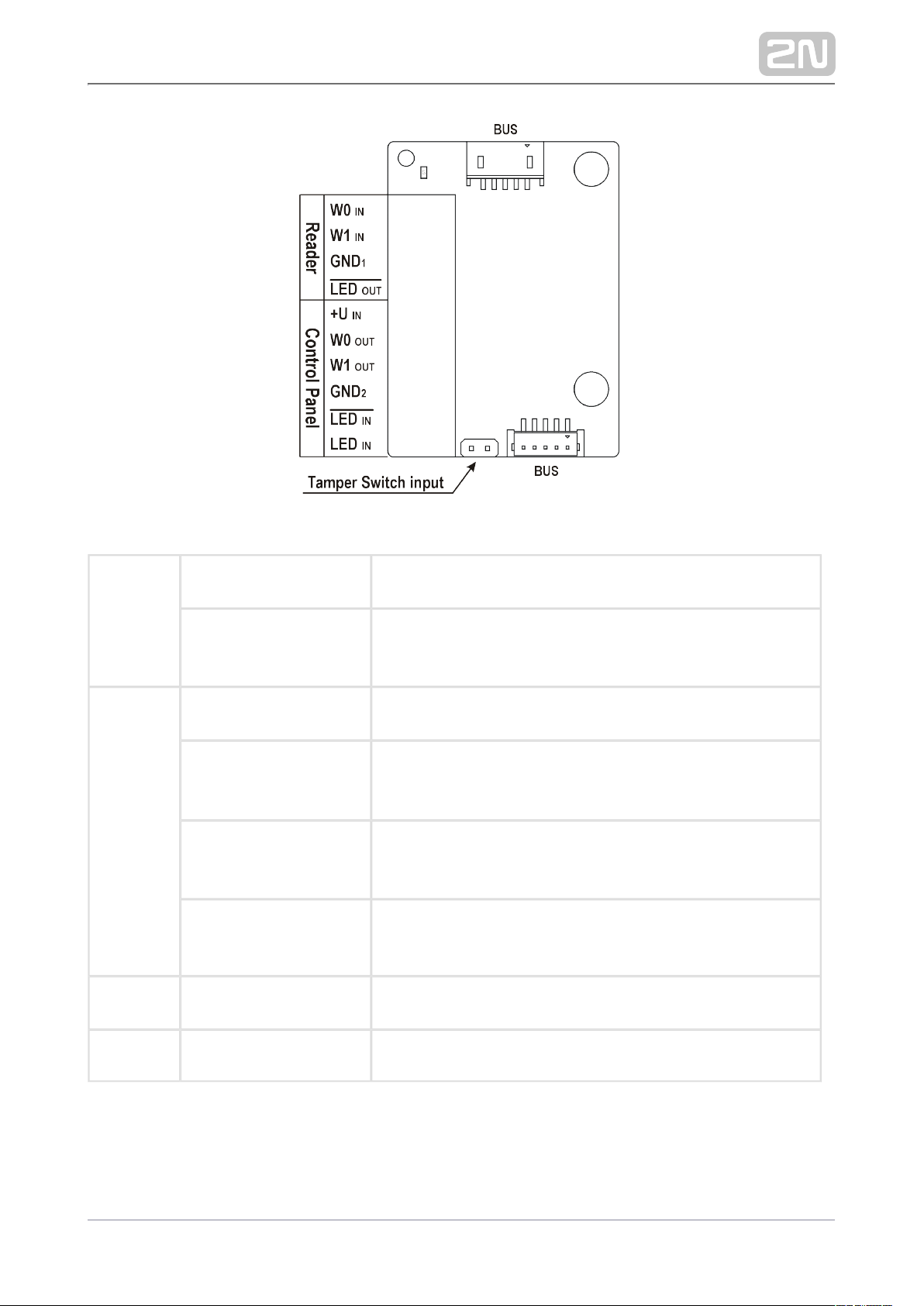
Reader W0 W1 GNDIN, IN, 1 Isolated 2-wire WIEGAND IN
LED OUT Isolated open LED OUT switched against GND (up to 24 1
V / 50 mA)
Control
Panel
+U IN +U input (5 to 15 V DC) for WIEGAND OUT power supply
W0 W1 GNDOUT, OUT,
2
Isolated 2-wire WIEGAND OUT
LED IN (negated) Isolated input for open LED IN, input activated by GND
2
connection
LED IN Isolated input for open LED IN, input activated by +U
connection
G +U WIEGAND OUT active supply LED indicatorIN
TAMPER Tamper switch (Part No. ) input9155038
2N TELEKOMUNIKACE a.s., www.2n.cz 73/105
Page 74
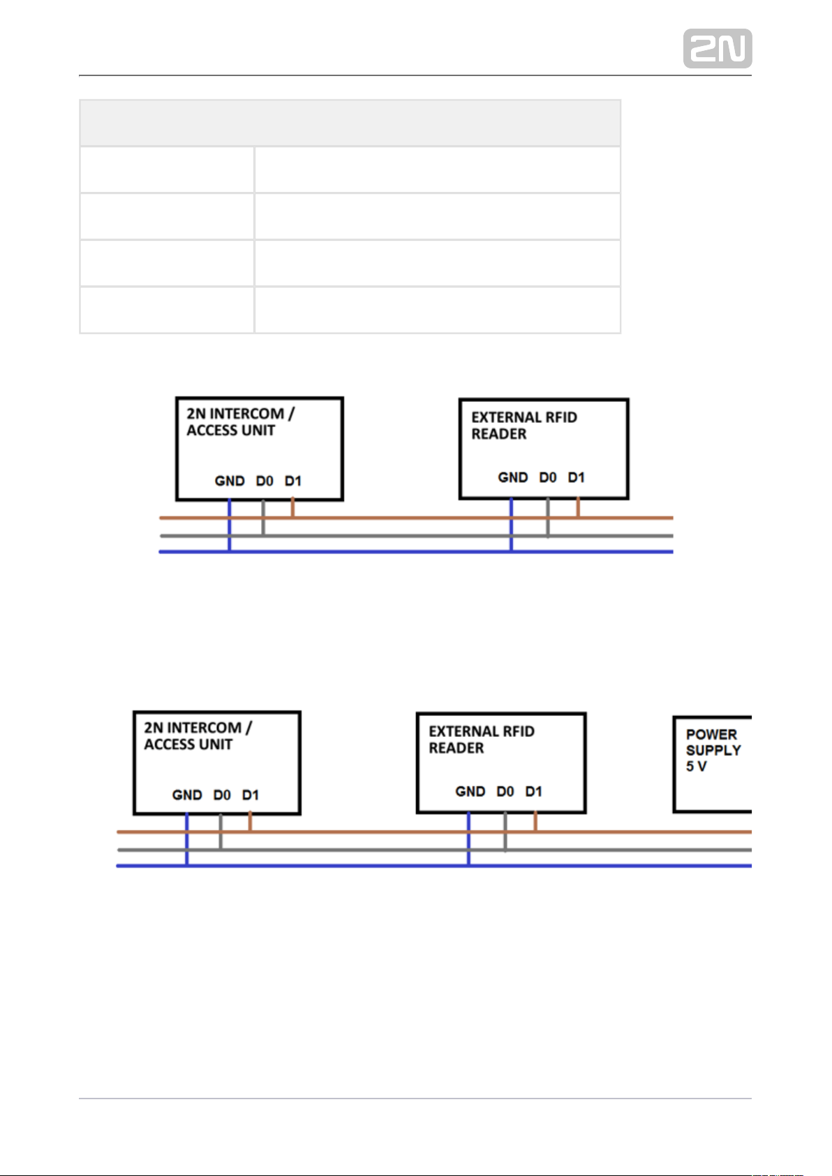
Technical Parameters of Wiegand Input
Current 5 mA
Input resistance 680 Ohm
Pulse length 50 μs
Inter-pulse interval approx. 2 ms
Recommended reader - bus driver wiring diagram
Recommended reader wiring diagram with OC output
2N TELEKOMUNIKACE a.s., www.2n.cz 74/105
Page 75
Tamper Switch Module
The Tamper switch module ( ) is one of the 2N IP Verso system Part No. 9155038
®
elements and helps secure the system against tampering.
The module contains two switches, which open whenever the front frame is
removed:
One switch leads directly to the terminal board and is connected to an
external security exchange (32 V DC / 50 mA max).
In coordination with the or I/O module (9155034) Wiegand module
, the other switch can be used for initiating alarm via the (9155037)
Automation interface in the configuration.2N IP Style
®
This module is not connected to the bus.
Caution
Remember to purchase the I/O module, Part No. 9155034, along with the
tamper switch.
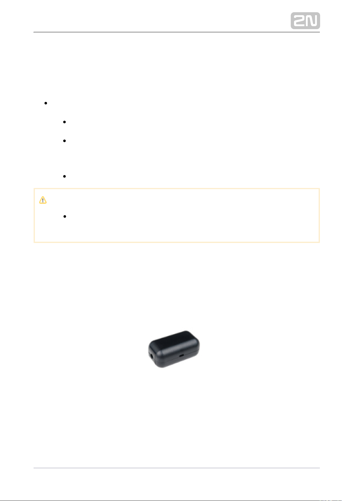
Security Relay
2N Security Relay®( ) is used for enhancing security between the Part No. 9159010
intercom and the connected electric lock. is designed for any 2N ®Security Relay 2N IP
with firmware 1.15 and higher. It significantly enhances security of the intercom
connected electric lock as it prevents lock opening by forced intercom tampering.
Function:
2N Security Relay® is a device installed between an intercom (outside the secured
area) and the electric lock (inside the secured area). includes a 2N Security Relay
®
relay that can only be activated if the valid opening code is received from the
intercom.
2N TELEKOMUNIKACE a.s., www.2n.cz 75/105
Page 76
Specifications:
Passive switch: NO and NC contacts, up to 30 V / 1 A AC / DC
Switched output:
Where the security relay is fed from the intercom, 9 to 13 V DC is available on
the output depending on the power supply (PoE: 9 V; adapter: source voltage of
minus 1 V) / 400 mA DC.
Where the security relay is fed from an external power supply, 12 V / 700 mA DC
is available on the output.
Dimensions: (56 x 31 x 24) mm
Weight: 20 g
Installation:
Install onto a two-wire cable between the intercom and the 2N Security Relay
®
electric lock inside the area to be secured (typically behind the door). The device is
powered and controlled via this two-wire cable and can thus be added to an existing
installation. Thanks to its compact dimensions, the device can be installed into a
standard mounting box.
Connection:
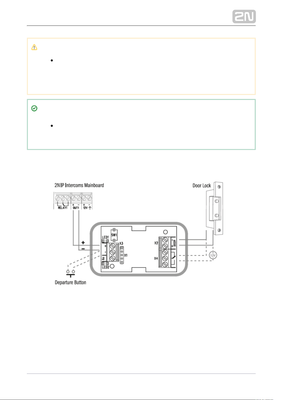
Connect to the intercom as follows:2N Security Relay
®
To the active output (OUT1)
Connect the electric lock to output as follows:2N Security Relay
®
To the switched output
To the passive output in series with the external power supply
The device also supports a Departure button connected between the ‘PB’ and ‘HeliosIP / IP Intercom terminals. Press the Departure button to activate the output for
5 seconds.
Status Signaling:
Green LED Red LED Status
flashing off Operational mode
2N TELEKOMUNIKACE a.s., www.2n.cz 76/105
Page 77
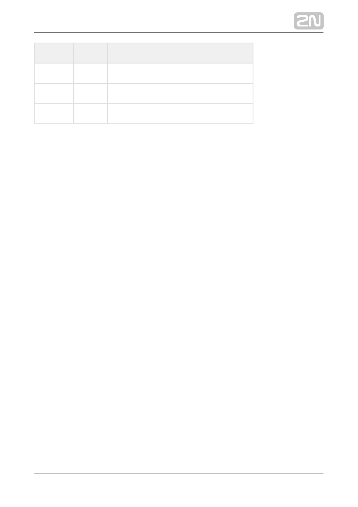
Green LED Red LED Status
on off Activated output
flashing flashing Programming mode – waiting for initialization
on flashing Error – wrong code received
Configuration:
Connect to the properly set Security intercom output. Refer to the 2N Security Relay
®
for details. Make sure that one LED at least Configuration Manual for 2N IP Intercoms
is on or flashing.
Press and hold the Reset button for 5 seconds to put the device in 2N Security Relay
®
the programming mode (both the red and green LEDs are flashing).
Activate the switch output using the keypad, phone, etc. The first code sent from the
intercom will be stored in the memory and considered valid. After code initialization,
will pass into the operational mode (the green LED is flashing).2N Security Relay
®
2N TELEKOMUNIKACE a.s., www.2n.cz 77/105
Page 78
Caution
Having reset the factory defaults on a device with firmware 2.18 or
higher, remember to reprogram using the 2N Security Relay
®
instructions above.
Tip
FAQ: 2N Security Relay – device description and use with the 2N IP
®
intercoms
Connection:
2N TELEKOMUNIKACE a.s., www.2n.cz 78/105
Page 79
3. Function and Use
This section describes the basic and extending functions of the product.2N IP Style
®
Here is what you can find in this section:
3.1 Configuration
3.2 2N® IP Style User Control
3.3 Intercom Control as Viewed by Internal User
3.4 Maintenance
3.5 Downloads
2N TELEKOMUNIKACE a.s., www.2n.cz 79/105
Page 80
3.1 Configuration
Configuration takes place typically via a web interface. Alternatively, configuration is
possible using the software or the service.2N Access Commander
®
My2N
Configure using your PC equipped with any Internet browser:2N IP Style
®
Launch your Internet browser (Chrome, Firefox, Internet Explorer, etc.).
Enter the IP address of your intercom ( , e.g.).http://192.168.1.100/
Log in using the username and password .Admin 2n
You have to know the IP address of your device to log in to the integrated web server.
Upon purchase, is set to the dynamic IP address mode – it retrieves the IP 2N IP Style
®
address automatically if there is a properly configured DHCP server in the LAN. If no
DHCP is available, can be operated in the static IP address mode. Refer 2N IP Style
®
to the for the configuration Configuration Manual for 2N IP Intercoms 2N IP Style
®
details.
If your device remains inaccessible (you have forgotten the IP address or the LAN
configuration has changed, for example), change the LAN settings using the hidden
menu on the device.
IP Address Retrieval
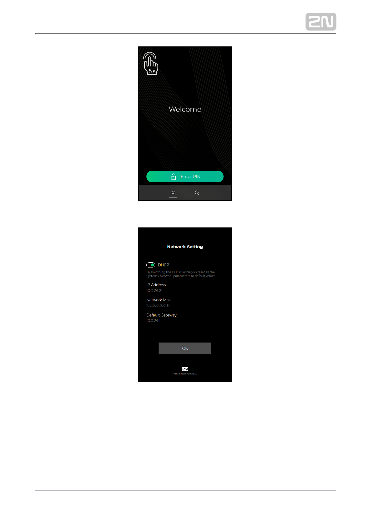
Wait until the end of the introductory animation on the display after starting
/restarting the device. The moment the home screen appears (after approx. 20 s),
place your finger in the left-hand upper corner of the display for approx. 5 s.
The IP address of the device will be shown in the hidden menu. The menu contains the
network mask, default gateway address and DHCP switch among others.
Tip
To retrieve the device IP address you can also use 2N Network
®
Scanner, which can be freely downloaded from .www.2n.cz
If the address is 0.0.0.0, then the device did not get the IP address from the DHCP
server and the static IP address (DHCP OFF) has to be used. If DHCP OFF is set, the
device static address is 192.168.1.100.
2N TELEKOMUNIKACE a.s., www.2n.cz 80/105
Page 81
Device Restart
To restart the device, disconnect the device from the power supply or use the web
interface in the System / Maintenance section. No configuration change appears after
the restart.
2N TELEKOMUNIKACE a.s., www.2n.cz 81/105
Page 82

1.
2.
Factory Default Reset
Located among the main unit connectors, the CONTROL button helps you reset the
factory default values.
Follow the instructions below to reset the factory default values:
Disconnect the device from the power supply.
Press and hold the CONTROL button.
Connect the device to the power supply.
Keep holding the button for a few seconds and then release it.
3.1.1 2N® IP Style LAN Location via 2N® Network Scanner
2N IP Style® is configured via the administration web server. Connect the device to
the LAN IP and make sure it is properly powered.
2N ® Network Scanner Description
The application helps find the IP addresses of the 2N devices in the LAN. Download
the app from the 2N web sites ( ). Make sure that Microsoft .NET Framework www.2n.cz
2.0 is installed for successful app installation.
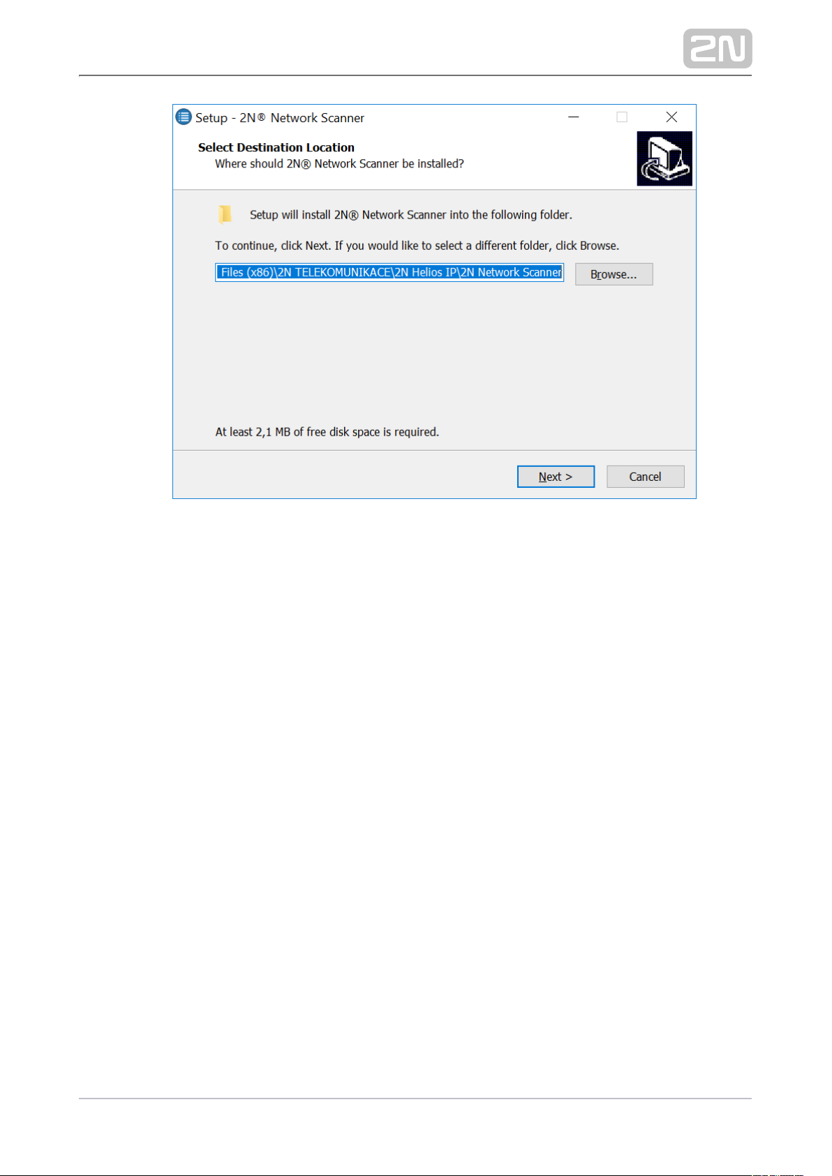
Run the installer.2N ®Network Scanner
Use the Setup Wizard for successful installation.
2N TELEKOMUNIKACE a.s., www.2n.cz 82/105
Page 83
3.
Setup Wizard of 2N® IP Network Scanner
Having installed , start the application using the 2N® IP Network Scanner
Microsoft Windows Start menu.
2N TELEKOMUNIKACE a.s., www.2n.cz 83/105
Page 84
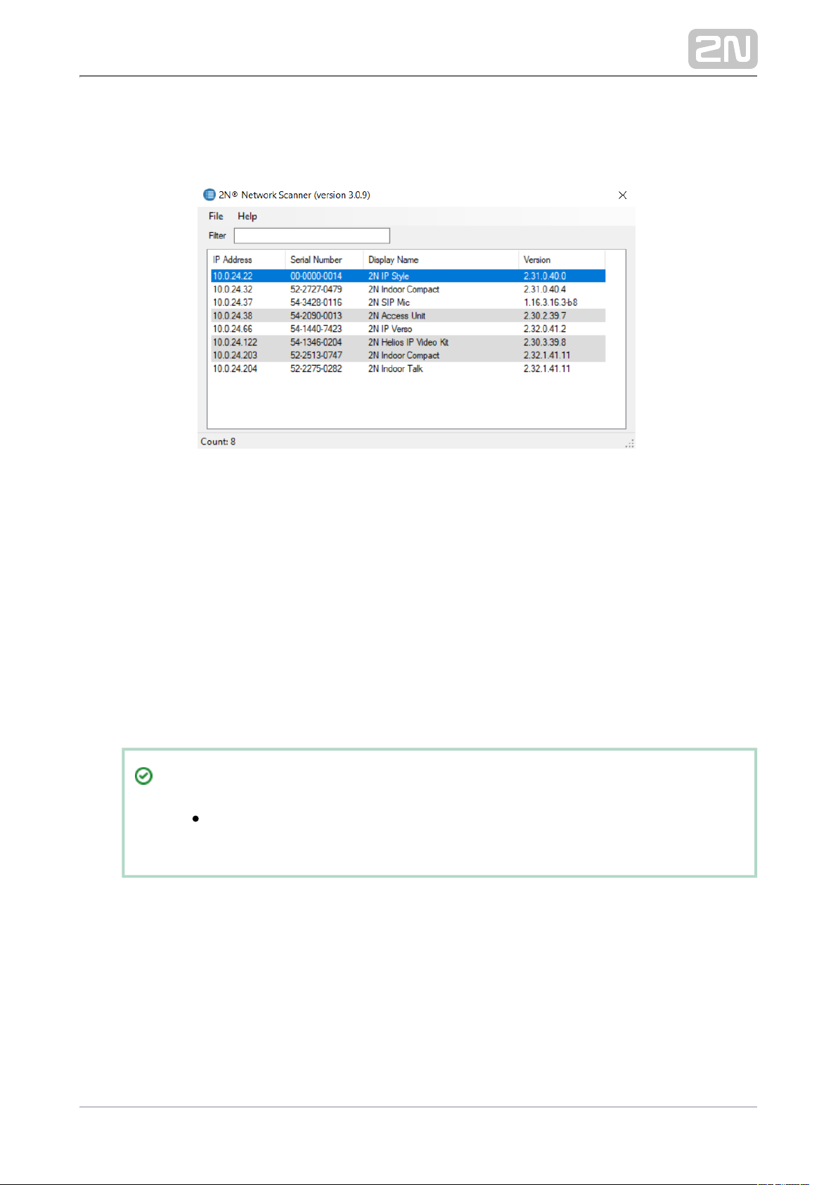
1.
Once started, the application begins to automatically search for all the 2N devices in
the LAN including their smart extensions which are DHCP/statically assigned IP
addresses. All the devices are then displayed in a table
Window of2N ®IP Network Scanner
Select the device to be configured and right-click it. Select 2N IP Style
®
Browse...
to open the administration web interface login window for 2N IP Style®
configuration. To change the device IP address, select and enter the
Config
required static IP address or activate DHCP. The default configuration password
is: 2n. If the found device is grey highlighted, its IP address cannot be configured
using this application. In that case, click Refresh to find the device again and
check whether multicast is enabled in your network.
Tip
Double click the selected row in the list to 2N® IP Network Scanner
access the device web interface easily.
2N TELEKOMUNIKACE a.s., www.2n.cz 84/105
Page 85
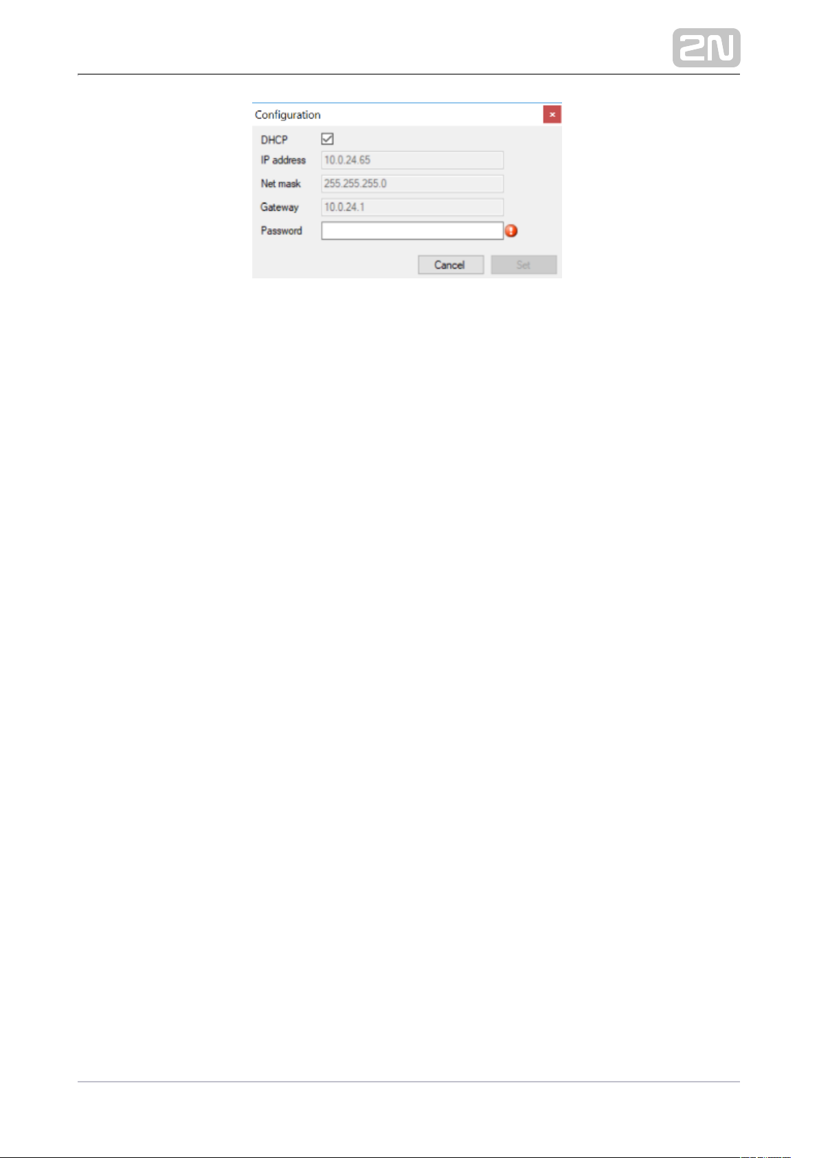
2N ®IP Network Scanner IP Address Change
2N TELEKOMUNIKACE a.s., www.2n.cz 85/105
Page 86
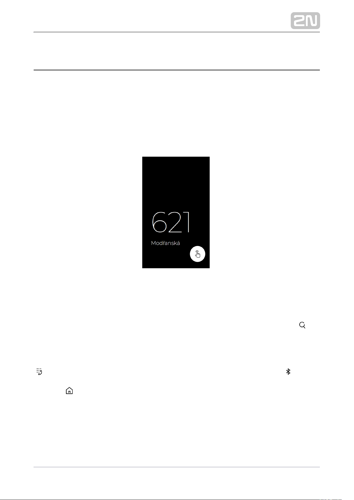
3.2 2N® IP Style User Control
Sleep Mode
2N IP Style® switches to the Sleep mode after an idle timeout (default value is 60 s).
In the Sleep mode, you can go to the Showcase mode to display a presentation or the
company logo/address (see Subs. of the Configuration Manual for IP 5.3.8 Display
Intercoms).
Touch any part of the display to cancel the Sleep mode and display the home page.
Sleep Mode
Home Page
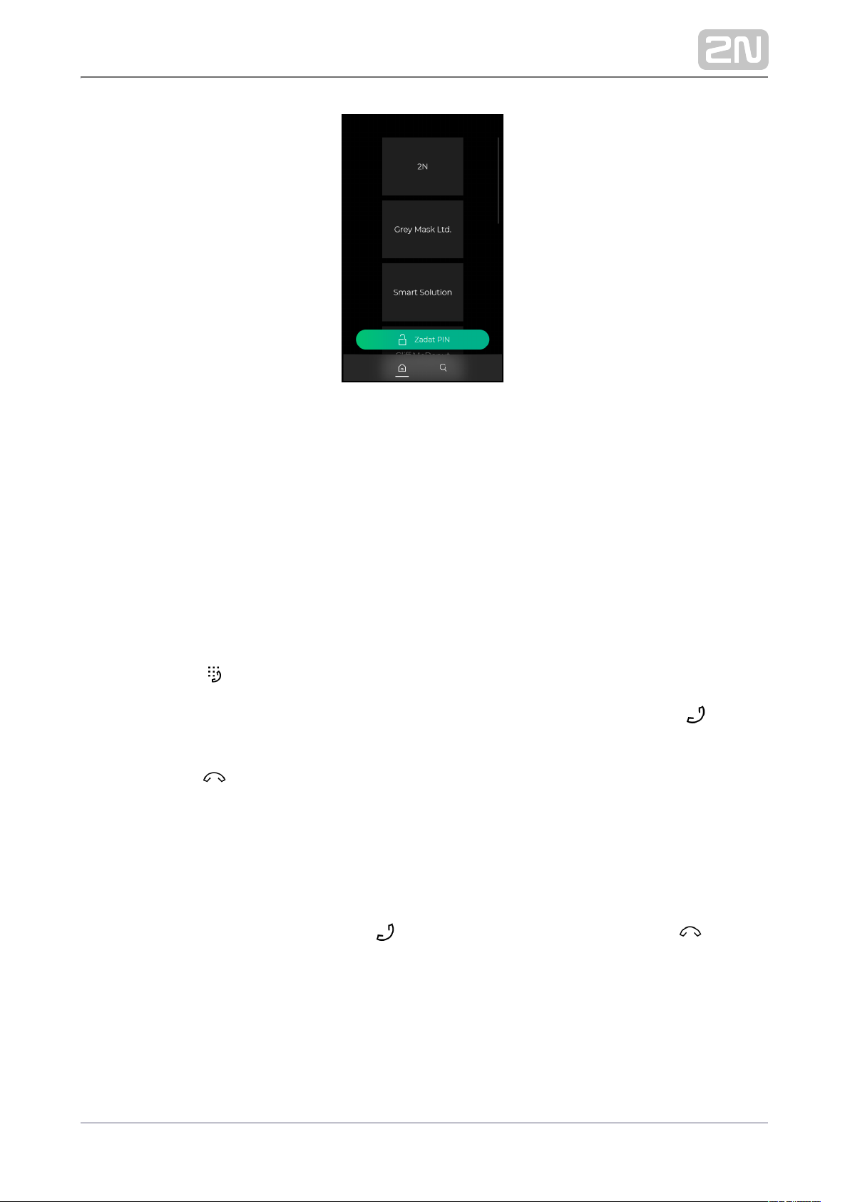
The home page displays the group / user name list to be called. Use the icon to
display a full-text array to retrieve contacts in the device directory. Also, the
possibility to enter the access code via the touch numeric keypad is offered.
If configured so, the home page can provide the possibility to call user virtual numbers
or get access via the mobile application under the icon .2N Mobile Key
®
The icon helps you return to the home page.
2N TELEKOMUNIKACE a.s., www.2n.cz 86/105
Page 87
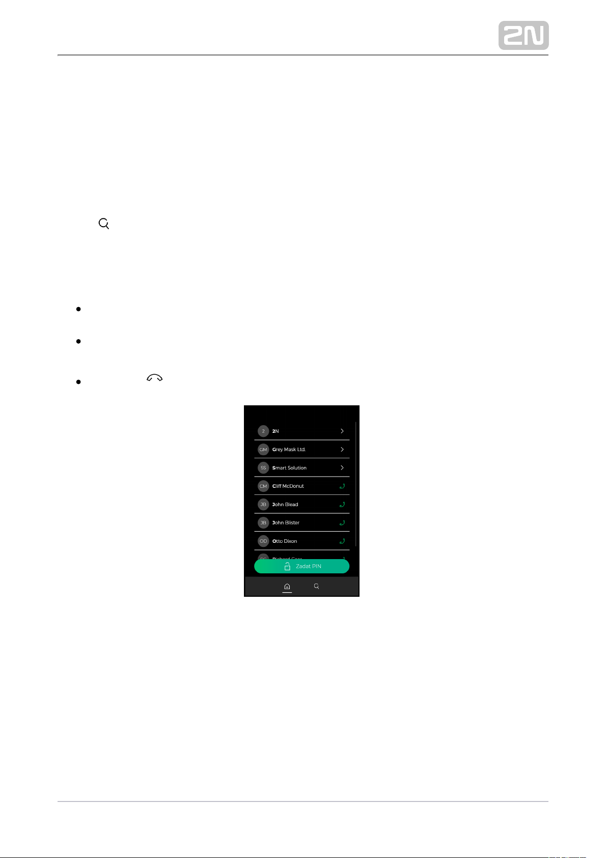
Calling to Phone Book Position
2N IP Style® displays the group / user name list. The Phone Book can 2N IP Style
®
contain up to 10 000 pre-programmed positions. The group / user list can be
displayed as a classic name list or as a set of cards (refer to Subs. of the 5.3.8 Display
Configuration Manual for IP Intercoms). The user groups are superior to the users, the
list is arranged in the alphabetical order.
Press to display a full-text array to retrieve a user by entering a few letters
representing the user name. All options are displayed from the list that contain the
searched string.
Procedure:
Touch the screen with your finger and move up and down to scroll up and down
in the group / user list.
Touch a selected user list position / card with your finger to make an outgoing
call to the user. An outgoing call will be set up.
Press the red button any time to end the call.
Name List
2N TELEKOMUNIKACE a.s., www.2n.cz 87/105
Page 88
1.
2.
3.
Cards
Virtual Number Call
If the (refer to Subs. of the Configuration Manual Phone function enabled 5.4.1 Phone
for IP Intercoms) parameter is selected, you can dial a user-defined phone number
using the numeric keypad.2N IP Style
®
Procedure:
Press the button.
Enter the phone number using the numeric keypad and repress the green
button for confirmation.
Press the red button any time to end the call.
Incoming Call Answering/Rejecting
If the automatic incoming call answering function is disabled (refer to Subs. 5.4.1 Phone
of the Configuration Manual for IP Intercoms), any incoming call to is 2N IP Style
®
signaled with loud ringing. Push the button to answer the call and the button
to reject the call.
2N TELEKOMUNIKACE a.s., www.2n.cz 88/105
Page 89

Door Opening (Switch Activation) by RFID Card
2N IP Style ®is equipped with a door unlocking switch. To activate this switch, tap a
valid card or chip on the integrated card reader. Remember to complete the user
access card ID (refer to Subs. of the Configuration Manual for IP intercoms) 5.2.1 Users
to get an RFID card / chip access.
Procedure:
Tap a valid RFID card / chip on the integrated card reader located in the bottom
part of the device, whose symbol is backlit.
A valid RFID card / chip use is notified visually and by a continuous switch
activation tone or a predefined unlocking user sound. An invalid RFID card / chip
use is signaled acoustically or using a user sound.
Door Opening (Switch Activation) by Code
2N IP Style ®is equipped with a door unlocking switch. Enter the valid code (refer to
Subs. of the Configuration Manual for IP Intercoms) using the touch 5.3.1 Switches
numeric keypad to activate this switch.
Procedure:
Enter the switch activating numeric code using the touch numeric keypad and
press the lock button for confirmation.
A valid code is notified visually and by a continuous switch activation tone or a
predefined unlocking user sound. An invalid code or interruption longer than as
defined in is signaled acoustically or using , Timeout for Entering Numbers
a user sound.
Door Opening (Switch Activation) by 2N ® Mobile Key
2N IP Style ®is equipped with a door unlocking switch. Activate this switch using the
authentication (refer to Subs. of the Configuration 2N Mobile Key
®
5.4.5 Mobile Key
manual for IP Intercoms) in your smartphone. The application is available for devices
with iOS 12 and higher (iPhone 4s and higher) or Android 6.0 Marshmallow and higher
(Bluetooth 4.0 Smart supporting phones).
Procedure:
According to the authentication mode:
Touch mode – press or drag from left to right on the display
(depending on the Bluetooth authentication setting) to activate the switch.
2N TELEKOMUNIKACE a.s., www.2n.cz 89/105
Page 90
Tap in app mode – unlock your smartphone, open the app and press the
virtual button to activate the switch.
Motion mode – motion has to be detected by the intercom camera to
activate the switch. Arrival in the proximity or waving of the hand will do.
Card mode – move your smartphone close to the integrated RFID card
reader to activate the switch.
A valid authentication is notified visually and by a continuous switch activation
tone or a predefined unlocking user sound. An invalid authentication is signaled
acoustically or using a user sound.
2N TELEKOMUNIKACE a.s., www.2n.cz 90/105
Page 91
3.3 Intercom Control as Viewed by Internal User
Call Answering
You can answer incoming calls from using your phone like any other calls. 2N IP Style
®
You can unlock the door, activate/deactivate a user/profile via your phone keypad
during the call. The calls, however, are time-limited to avoid unintentional blocking of
the line. Set the maximum call duration in the Call time limit parameter 2N IP Style
®
(refer to Subs. of the Configuration Manual). Press # on your phone Phone / Calls
anytime to extend the call time. The automatic call termination is signaled with a short
beep 10 s before the call end.
Calling to 2N ® IP Style
2N IP Style ®allows you to answer incoming calls. Set the required parameters in the
Incoming calls group (refer to Subs. of the Configuration Manual).Phone / Calls
Door Opening (Switch Activation) by Code
2N IP Style ®is equipped with a door unlocking switch. Enter the valid code (refer to
Subs. of the Configuration Manual) using your phone keypad to Hardware / Switches
activate this switch.
Procedure:
Enter the switch 1 or 2 activating code using your phone keypad and press
for confirmation. (Confirmation is unnecessary if the Lock code without
confirmation is enabled, refer to the Hardware / Switches / Advanced
subsection).
A valid code is signaled acoustically . An invalid code or interruption longer
than as defined in is signaled acoustically , Timeout for Entering Numbers
.
2N TELEKOMUNIKACE a.s., www.2n.cz 91/105
Page 92
Note
Codes 00 and 11 are reserved for DTMF-based door opening.
2N TELEKOMUNIKACE a.s., www.2n.cz 92/105
Page 93
3.4 Maintenance
If used frequently, the device surface gets dirty. Use a piece of soft cloth moistened
with clean water to clean the device. It is recommended that the principles below are
followed while cleaning:
Do not use aggressive detergents (such as abrasives or strong disinfectants).
Use suitable cleaning agents for glass lens cleaning (cleaners for glasses, optical
devices, screens, etc.).
Clean the device in dry weather in order to make waste water evaporate quickly.
We recommend that IT cleaning wipes are used.
Anticovid
To disinfect the surface of the device against bacteria and viruses (AntiCovid) and maintain the hygienic conditions of critical surfaces and
touch points, we recommend that you use the Zoono – Microbe Shield
Surface Sanitiser spray.
Warning
Prevent water from getting inside the intercom.
Do not use alcohol-based cleaners.
Avoid peroxide-based cleaners.
Do not use lye-based (sodium hydroxide) cleaners.
Caution
Use the product for the purpose it was designed and manufactured for,
in compliance herewith.
The manufacturer reserves the right to modify the product in order to
improve its qualities.
2N IP Style® contains no environmentally harmful components. When
the product's service life is exhausted, dispose of the product in
accordance with applicable legal regulations.
2N TELEKOMUNIKACE a.s., www.2n.cz 93/105
Page 94

3.5 Downloads
Software
2N USB driver
®
2N IP Eye
®
2N Network Scanner
®
2N TELEKOMUNIKACE a.s., www.2n.cz 94/105
Page 95
4. Technical Parameters
Signaling protocol
SIP (UDP, TCP, TLS)
Buttons
Button design: white-backlit transparent buttons with replaceable nametags
Button count: 1 and increments of 5
Button extenders: up to 29 modules, limited by power supply
Numeric keypad:optional
Audio
Microphone: 2 integrated microphones
Amplifier: 2 x 4 W (class D) amplifier
Speaker: 2 x 4 W / 4 Ω
Sound pressure level : (SPL max) 85 dB (for 1 kHz, distance 1 m)
Output LINE OUT: 1 VRMS / 600 Ω
Volume control :adjustable with automatic adaptive mode
Full Duplex:yes (AEC)
Speech transmission index (STI): 0.89
Audio stream
Protocols: RTP / RTSP / SRTP
Codecs: G.711, G.729, G.722, L16/16kHz
2N TELEKOMUNIKACE a.s., www.2n.cz 95/105
Page 96
Camera
Sensor:: 1/2.7'' color CMOS
JPEG resolution: up to 2560 (H) x 1920 (V), (4:3); max QHD (16:9)
Video resolution: up to 2560 (H) x 1920 (V), (4:3); max QHD (16:9)
Frame rate: up to 60 frames per s
Sensor sensitivity: 14000 V/lux-sec
View angle: 144 ° (H), 126 ° (V)
Infrared light: yes
Sensor sensitivity without IR light: 0.1 Lux ± 20 %
Focal length: 1.7 mm
Video stream
Protocols: RTP / RTSP / SRTP / HTTP
Codecs: H.264, M-JPEG
IP camera function:: yes, ONVIF v2.4 profile S compatible
2N TELEKOMUNIKACE a.s., www.2n.cz 96/105
Page 97
Bandwidth
Audio codecs
PCMA, PCMU – 64 kbps (with 85.6 kbps headers)
G.729 – 16 kbps (with 29.6 kbps headers)
G.722 – 64 kbps (with 85.6 kbps headers)
L16 / 16 kHz – 256 kbps (with 277.6 kbps headers)
V i d e o c o d e c s
Set the video codec data flows in the Services / Phone / Video menu for calls
and in the Services / Streaming / RTSP menu for streaming. The set bandwidth
represents the value that the codec has to approach on a long-time average. The
data flows can vary depending on the scene to be scanned.
The measured data flow values correspond to the test view of a person standing
in front of the intercom.
H.264
Low quality: QVGA (320 x 240), 10 fps, 256 kbps: 181 kbps (with 190 kbps
headers)
Medium quality: VGA (640 x 480), 15 fps, 768 kbps: 600 kbps (with 661
kbps headers)
High quality: VGA (640 x 480), 30 fps, 2048 kbps: 1319 kbps (with 1372
kbps headers)
MJPEG
Low quality: QVGA (320 x 240), 10 fps, quality 70: 435 kbps with headers
Medium quality: QVGA (640 x 480), 15 fps, quality 85: 506 kbps
High quality: QVGA (1280 x 960), 15 fps, quality 95: 8 Mbps
Interface
Power Supply: 12 V ±15 % / 4 A DC or PoE+
PoE: PoE+ 802.3at
LAN: 10/100BASE-TX s Auto-MDIX, RJ-45
Recommended cabling: Cat-5e or higher
Supported protocols: SIP2.0, SIPS, DHCP opt. 66, SMTP, SNMP, TR069, 802.1x,
RTSP, RTP, SRTP, TFTP, HTTP, HTTPS, Syslog, ONVIF
Passive switch: NO and NC contacts, up to 30 V / 1 A AC / DC
12 V / 0.6 A DCActive switch output:
−30 V to +30 V DCPassive / active input:
RFID card reader
Supported 125 kHz cards
EM4xxx
2N TELEKOMUNIKACE a.s., www.2n.cz 97/105
Page 98
Supported cards in 13.56 MHz NFC version (only card ID is read)
ISO14443A (Mifare, DESFire)
PicoPass (HID iClass)
FeliCa
ST SR(IX)
2N Mobile Key
®
Supported secured cards in 13.56 MHz NFC version
HID SE (Seos, iClass SE, Mifare SE)
Maximum H – field strength at 10 m for 125 kHz version: 1.492e-3 W/m
2
Maximum H – field strength at 10 m for 13.56 MHz version: 3.747e-4 W/m
2
Bluetooth
Bluetooth 4.2 in compliance with BLE (Bluetooth Low Energy)
Security: asymmetric RSA-1024 and symmetric AES-128 encryption
Range: adjustable (short ~ 0.5m, medium ~ 2m, long ~ up to 10m)
Support of mobile applications: Android 6 and higher, iOS 12 and higher
Touch display
Resolution: 10.1’’ 1280 x 800 TFT IPS
Contrast ratio: 800
Brightness: 900 cd/m2
Viewing angle: 85 ° from any direction
Numeric keypad: touch numeric keypad
Touch buttons: touch display
Directory: residential / business (for 10 000 users)
I/O module (optional)
External
Dimension: 43 (W) x 31.5 (H) x 1.5 (D) mm
Wiegand module (optional)
External
Dimensions: 43 (W) x 31.5 (H) x 1.5 (D) mm
Mechanical properties
2N TELEKOMUNIKACE a.s., www.2n.cz 98/105
Page 99
Cover: Hardened glass
Body: EN-AW6060
Surfacing:
Wet coatingRAL:
Operating temperature: °C to 60 °C−30
Working relative humidity: 10 % – 95 % (non-condensing)
Storage temperature: °C to 70 °C−30
Dimensions
Surface mounting: 170 (W) x 355 (H) mm x 40 mm (D)
Flush mounting: 170 (W) x 355 (H) mm x 22 mm (D)
Weight: 1950 g
Cover rating: IP65
Resistance level: IK08
2N TELEKOMUNIKACE a.s., www.2n.cz 99/105
Page 100

5. Supplementary Information
5.1 Troubleshooting
5.2 Directives, Laws and Regulations
5.3 General Instructions and Cautions
2N TELEKOMUNIKACE a.s., www.2n.cz 100/105
 Loading...