


TOA 900 SERIES II
MIXER POWER AMPLIFIER
Operating Instructions
A-903MK2
A-906MK2
A-912MK2
TO REDUCE THE RISK OF ELECTRICAL SHOCK, DO NOT REMOVE COVER.
NO USER SERVICEABLE PARTS INSIDE. REFER SERVICING TO QUALIFIED
SERVICE PERSONNEL.
THE LIGHTNING FLASH WITH ARROWHEAD WITHIN A TRIANGLE IS INTENDED TO TELL THE USER THAT PARTS INSIDE THE PRODUCT ARE A RISK OF ELECTRIC SHOCK TO PERSONS.
THE EXCLAMATION POINT WITHIN A TRIANGLE IS INTENDED TO TELL THE USER THAT IMPORTANT OPERATING AND SERVICING INSTRUCTIONS ARE IN THE PAPERS WITH THE APPLIANCE.
Please follow the instructions in this manual to obtain the optimum results from this unit.
We also recommend that you keep this manual handy for future reference.
TOA Corporation

Contents
General description |
3 |
Features |
3 |
Nomenclature |
|
Front panel |
4 |
Rear panel |
5 |
Input connections |
6 |
Output connections (A-903MK2) |
6~7 |
Output connections (A-906MK2/A-912MK2) |
7~8 |
Muting and remote volume control connection |
8 |
Rack mounting |
8 |
Operation |
9 |
Volume adjustment |
9 |
Tone control adjustment |
9 |
Installation |
9 |
Servicing |
9 |
Specifications |
10 |
Appearance (A-903MK2) |
11 |
Appearance (A-906MK2/A-912MK2) |
12 |
–2–
General Description
The TOA A-903MK2, A-906MK2 and A-912MK2 Mixer Power Amplifiers control and mix up to eight
independent input signals. The A-903MK2 delivers up to 30 watts of output power, the A-906MK2 60 watts
and A-912MK2 120 watts.
Optional plug-in modules are available for use with these mixer power amplifiers to provide versatility for a
wide range of operating applications. Edge connectors on the rear of the unit permit the selection of the TOA plug-in modules.
The mixer power amplifiers have output terminals to match 4- or 8-ohm speaker systems, or speaker distribution systems may be connected to 25or 70-volt terminals, and can be rack mounted by using optional rack mounting bracket MB-25B. The optional perforated panel PF-511 provides suitable ventilation, finished in color to match the mixer power amplifiers.
Features
1.8-channel mixer power amplifier
2.Wide frequency response : 20~20,000 Hz ± 1 dB
3.Low distortion and noise level
4.Remote master volume control
5.Excellent output regulation
6.Bass and treble controls
7.Bridging input/output
8.Self-protection circuitry design
9.Signal processing input/output
10.Varied output impedances : 4 ohms, 8 ohms, 25 and 70 volts
11.A full range of plug-in modules
12.Portable or rack mounting type
–3–
Nomenclature
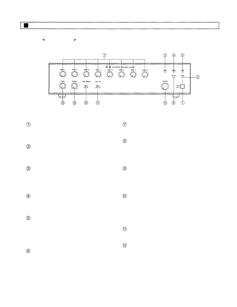
Front Panel
Power Switch
Applies line power. Two-position push button switch for on/off modes.
Power Indicator LED
Green LED lights when the power is switched "ON".
Signal Indicator LED
Green LED lights when more than –30 dB signal level is fed to the inputs by means of the input and master volume controls.
Normal Indicator LED
Yellow LED lights when fed to the proper signal level.
Peak Indicator LED
Red LED lights when amplifier approaches clipping level. If steady lit, the input level control should be turned down until the LED flashes only intermittently.
Protection Indicator LED
Remains lit for about 5 seconds after power
switch is turned ON.
Input Volume Controls
Adjust gain of input #1 ~#8 respectively.
Bass Control
Modifies bass response. Turn clockwise to boost, counter-clockwise to attenuate the bass response. Tone is flat at center.
Treble Control
Modifies treble response. Turn clockwise to boost, counter-clockwise to attenuate the treble response. Tone is flat at center.
Tone Switch
Selects ON/OFF of the BASS and TREBLE controls. When slided to OFF, BASS and TREBLE controls are active. When slided to ON, they become inactive to make tone flat.
Low-Cut Switch
Cuts off unnecessary low frequency.
Master Volume Control
Adjusts overall gain of the unit.
–4–
 Loading...